EP2892148B1 - Control system and method for an electric three-phase variable speed motor - Google Patents
Control system and method for an electric three-phase variable speed motor Download PDFInfo
- Publication number
- EP2892148B1 EP2892148B1 EP14150005.8A EP14150005A EP2892148B1 EP 2892148 B1 EP2892148 B1 EP 2892148B1 EP 14150005 A EP14150005 A EP 14150005A EP 2892148 B1 EP2892148 B1 EP 2892148B1
- Authority
- EP
- European Patent Office
- Prior art keywords
- current
- motor
- axis
- currents
- ratio value
- Prior art date
- Legal status (The legal status is an assumption and is not a legal conclusion. Google has not performed a legal analysis and makes no representation as to the accuracy of the status listed.)
- Active
Links
- 238000000034 method Methods 0.000 title claims description 16
- 230000007274 generation of a signal involved in cell-cell signaling Effects 0.000 claims description 51
- 230000004907 flux Effects 0.000 claims description 10
- 238000001914 filtration Methods 0.000 claims description 9
- 230000001419 dependent effect Effects 0.000 claims description 8
- 230000006698 induction Effects 0.000 claims description 6
- 229920006395 saturated elastomer Polymers 0.000 claims description 6
- 230000001052 transient effect Effects 0.000 claims description 4
- 238000010586 diagram Methods 0.000 description 10
- 239000013598 vector Substances 0.000 description 4
- 238000002347 injection Methods 0.000 description 3
- 239000007924 injection Substances 0.000 description 3
- 230000004044 response Effects 0.000 description 3
- 230000000694 effects Effects 0.000 description 2
- 230000005415 magnetization Effects 0.000 description 2
- 230000009466 transformation Effects 0.000 description 2
- 238000000844 transformation Methods 0.000 description 2
- 230000002730 additional effect Effects 0.000 description 1
- 238000004378 air conditioning Methods 0.000 description 1
- 230000008859 change Effects 0.000 description 1
- 238000004590 computer program Methods 0.000 description 1
- 238000010438 heat treatment Methods 0.000 description 1
- 238000012886 linear function Methods 0.000 description 1
- 230000004048 modification Effects 0.000 description 1
- 238000012986 modification Methods 0.000 description 1
- 238000005457 optimization Methods 0.000 description 1
- 230000010355 oscillation Effects 0.000 description 1
- 238000005086 pumping Methods 0.000 description 1
- 238000009423 ventilation Methods 0.000 description 1
Images


Classifications
-
- H—ELECTRICITY
- H02—GENERATION; CONVERSION OR DISTRIBUTION OF ELECTRIC POWER
- H02P—CONTROL OR REGULATION OF ELECTRIC MOTORS, ELECTRIC GENERATORS OR DYNAMO-ELECTRIC CONVERTERS; CONTROLLING TRANSFORMERS, REACTORS OR CHOKE COILS
- H02P21/00—Arrangements or methods for the control of electric machines by vector control, e.g. by control of field orientation
- H02P21/14—Estimation or adaptation of machine parameters, e.g. flux, current or voltage
-
- H—ELECTRICITY
- H02—GENERATION; CONVERSION OR DISTRIBUTION OF ELECTRIC POWER
- H02P—CONTROL OR REGULATION OF ELECTRIC MOTORS, ELECTRIC GENERATORS OR DYNAMO-ELECTRIC CONVERTERS; CONTROLLING TRANSFORMERS, REACTORS OR CHOKE COILS
- H02P21/00—Arrangements or methods for the control of electric machines by vector control, e.g. by control of field orientation
- H02P21/0085—Arrangements or methods for the control of electric machines by vector control, e.g. by control of field orientation specially adapted for high speeds, e.g. above nominal speed
- H02P21/0089—Arrangements or methods for the control of electric machines by vector control, e.g. by control of field orientation specially adapted for high speeds, e.g. above nominal speed using field weakening
Definitions
- the technical field is generally directed to electric three-phase variable speed motors and to scalar based control thereof.
- Control arrangements for induction motor drives may comprise those, which implement constant V/f control in open loop mode. Such control arrangements may potentially operate the motor drives at enhanced efficiency, by incorporating MTPA (maximum torque per ampere) control in scalar mode.
- MTPA maximum torque per ampere
- the MTPA control is a model based approach using current angle control. Typically, the stator currents of the motor are resolved into equivalent d and q axis currents and then the d axis current reference is controlled which maximizes motor efficiency.
- Fig. 1 is a schematic diagram of a control system 11 for an electric three-phase variable speed motor 12 comprising such a scalar based control arrangement 14 for controlling an inverter 13, which provides power to the motor 12.
- the control system comprises also current sensors 15 configured to detect currents of the motor.
- the control arrangement comprises a d and q axis currents determining module 16 configured to determine the d and q axis currents i sd , i sq based on the detected currents and a reference phase ⁇ *, a low pass filter block 17a, an MTPA control block 17b, and a switching signal generation module 18.
- the current sensors 15 may be configured to detect two i a , i b of the three currents i a , i b i c of the three-phase motor 12.
- the d and q axis currents determining module 16 may in such instance comprise a first current determining block 16a configured to determine the three currents i a , i b i c based on the detected currents i a , i b and a second current determining block 16b configured to determine the d and q axis currents i sd , i sq based on the three currents i a , i b i c and a reference phase ⁇ *.
- the q axis current i sq is input to the low pass filter block 17a from the d and q axis currents determining module 16 and is low pass filtered for control stability in the low pass filter block 17a to form the reference q axis current i* sq , which is input to the switching signal generation module 18.
- the d and q axis currents i sd , i sq are input to the MTPA control block 18, which is configured to generate a reference d axis current i* sd based on the determined d and q axis currents i sd , i sq and a ratio value such that the ratio of the d and q axis currents is equal to the ratio value, wherein the ratio value is set to unity.
- the switching signal generation module 18 is configured to generate PWM modulated switching signals to control the inverter 13 based on the reference d and q axis currents i* sd , i* sq .
- the switching signal generation module 18 comprises a first block 18a, to which the reference d and q axis currents i* sd , i* sq and a reference speed ⁇ * are input.
- the first block 18a is configured to determine the reference d and q axis voltages u* sd , u* sq from reference d and q axis currents i* sd , i* sq .
- a second block 18b which is configured to repeatedly generate voltage vectors u* sa , u* sb , u* sc based on the d and q axis voltages u* sd , u* sq and a reference phase ⁇ *.
- the voltage vectors are PWM modulated in a third block 18c to form PWM modulated switching signals S a , S b , S c , and the PWM modulated switching signals S a , S b , S c are input to the inverter 13.
- the second current determining block 16b of the d and q axis currents determining module 16 and the second block 18b of the switching signal generation module 18 may be implemented using dq-abc transformations.
- the model based MTPA control approach disclosed above works well if the induction motor magnetization flux is assumed linear function of magnetizing current (constant magnetizing inductance). In reality, this is not true due to the saturation characteristics of motor magnetic flux. At partial speeds and/or low flux levels, the performance is optimum since the motor flux is not saturated at this operation condition. But at nominal speed or when the motor voltage is near the nominal value, due to magnetizing inductance saturation effects, the MTPA control approach as described above does not lead to optimum current operation.
- a first aspect refers to a control system for an electric three-phase variable speed motor having a stator and rotor, wherein the control system comprises an inverter for providing power to the electric motor, a scalar based control arrangement for controlling the inverter, and current sensors for measuring motor currents.
- the control arrangement comprises a d and q axis currents determining module, a filter block, an MTPA control block, a switching signal generation module, and a fine adjustment module.
- the current sensors are configured to repeatedly detect currents of the motor and the d and q axis currents determining module is configured to repeatedly determine d and q axis currents based on the detected currents.
- the filter block is configured to repeatedly filter the determined q axis current, thereby generating a reference q axis current
- the MTPA control block is configured to repeatedly generate a reference d axis current based on the d and q axis currents and a ratio value such that the ratio of the d and q axis currents is equal to the ratio value, wherein the ratio value is unity.
- the switching signal generation module is configured to repeatedly generate switching signals to control the inverter based on the reference d and q axis currents.
- the fine adjustment module is configured to calculate a magnitude of a current or power of the motor and to determine a compensation ratio value based on the magnitude of a current or power of the motor, which compensation ratio value is added to the ratio value to form an adjusted ratio value, which adjusted ratio value when being used by the MTPA control block would cause the motor to operate in a condition wherein the magnitude of a current or power of the motor is minimized.
- the MTPA control block is configured to repeatedly generate an adjusted reference d axis current based on the d and q axis currents and the adjusted ratio value such that the ratio of the d and q axis currents is equal to the adjusted ratio value
- the switching signal generation module is configured to repeatedly generate switching signals to control the inverter based on the adjusted reference d axis current and the reference q axis current.
- a control system which can use the scalar MTPA control approach at unsaturated conditions, and add the proposed fine adjustment when needed, e.g. at saturated conditions or at conditions close to saturation.
- the fine adjustment module may be configured to determine the optimum compensation ratio value in an iterative algorithm based on the perturb and observe principle. That is, a step disturbance signal is injected into the controlling variable and the response, i.e. sign and amplitude, in the controlled variable is monitored. The compensation signal is generated such that the controlled variable is moved to the optimum point where the amplitude of controlled variable is at its minimum (or maximum).
- This type of control is suitable for the systems which inherently show a minimum point (or maximum point) as the controlling variable is changed across its span.
- the MTPA based control is a perfect match for such control since the current variation (or efficiency variation) shows a minimum point for variation in the motor flux.
- the fine adjustment module may be configured to determine the optimum compensation ratio value by means of performing the following algorithm:
- the fine adjustment module may be configured to switch off the perturbation signal when the difference falls short of a threshold level and the optimum compensation ratio value is obtained as the accumulatively added compensation ratio value.
- a second aspect refers to a control system for an electric three-phase variable speed motor having a stator and rotor, the control system comprising an inverter for providing power to the electric motor, a scalar based control arrangement for controlling the inverter, and current sensors for measuring currents in the motor.
- the control arrangement comprises a d and q axis currents determining module, a filter block, an MTPA control block, a switching signal generation module, and a fine adjustment module.
- the current sensors are configured to repeatedly detect currents of the motor, the d and q axis currents determining module is configured to repeatedly determine d and q axis currents based on the detected currents; the filter block is configured to repeatedly filter the determined q axis current, thereby generating a reference q axis current, and the MTPA control block is configured to repeatedly generate a reference d axis current based on the d and q axis currents and a ratio value such that the ratio of the d and q axis currents is equal to the ratio value, wherein the ratio value is unity.
- the switching signal generation module is configured to repeatedly generate switching signals to control the inverter based on the reference d and q axis currents.
- the fine adjustment module is configured to calculate the magnitude of a current or power of the motor and to determine an optimum compensation current based on the calculated magnitude of a current or power of the motor.
- the optimum compensation current is added to the reference d axis current to form an adjusted reference d axis current, which adjusted reference d axis current when being used by the switching signal generation module would cause the motor to operate in a condition wherein the magnitude of a current or power of the motor is minimized, wherein the switching signal generation module is configured to repeatedly generate switching signals to control the inverter based on the adjusted reference d axis current and the reference q axis current.
- the ratio value which is used by the MTPA control module, is not fine tuned, but instead a reference current output from the MTPA control block is fine tuned by means of adding a compensation current to the reference d axis current output from the MTPA block, and to feed the switching signal generation module with this sum as the reference d axis current.
- the fine adjustment module may be configured to determine the optimum compensation current in an iterative algorithm based on the perturb and observe principle in a similar manner as disclosed with respect to the first aspect.
- the fine adjustment module is configured to determine the optimum compensation current by means of performing the following algorithm while the output reference d axis current from the MTPA control block is held latched:
- the fine adjustment module may be configured to switch off the perturbation signal when the difference falls short of a threshold level and the optimum compensation current is obtained as the accumulatively added compensation current.
- the magnitude of a current or power of the motor may be a magnitude of a current of the motor and is calculated as the mean square root of the determined d and q axis currents or from the detected currents.
- the magnitude of a current or power of the motor may be a magnitude of an estimated power of the motor and may be calculated based on reference voltages calculated based on the reference d and q axis currents and (ii) the determined d and q axis currents or the detected currents.
- the magnitude of a current or power of the motor is a magnitude of a power of the motor and is calculated based on detected voltages and currents of the motor.
- the control system may be configured to power the stator of an induction motor, and the current sensors may be configured to repeatedly detect stator currents of the motor.
- the fine adjustment module may be configured to be operated at saturated flux operation conditions.
- the fine adjusting may be reset or cancelled when a changed operating condition of the motor, e.g. due to a transient step in torque and/or speed of the motor, is detected, and the fine adjusting may be performed or activated again when a steady state of the motor has been detected.
- a third aspect refers to a control method for an electric three-phase variable speed motor having a stator and rotor, wherein the control method comprises the following steps: (i) receiving repeatedly detected currents of the motor; (ii) repeatedly determining d and q axis currents based on the received currents; (iii) repeatedly filtering the determined q axis current, thereby generating a reference q axis current; (iv) applying an MTPA control scheme in which a reference d axis current is repeatedly generated based on the determined d and q axis currents and a ratio value such that the ratio of the d and q axis currents is equal to the ratio value, wherein the ratio value is unity; (v) repeatedly generating switching signals to control an inverter based on the reference d and q axis currents wherein the inverter is operable to power the motor; (vi) fine adjusting the MTPA control scheme by means of calculating a magnitude of a current or power of the
- a fourth aspect refers to a control method for an electric three-phase variable speed motor having a stator and rotor, wherein the control method comprises the following steps: (i) receiving repeatedly detected currents of the motor; (ii) repeatedly determining d and q axis currents based on the detected currents; (iii) repeatedly filtering the determined q axis current, thereby generating a reference q axis current; (iv) applying an MTPA control scheme in which a reference d axis current is repeatedly generated based on the determined d and q axis currents and a ratio value such that the ratio of the d and q axis currents is equal to the ratio value, wherein the ratio value is unity; (v)repeatedly generating switching signals to control an inverter based on the reference d and q axis currents wherein the inverter is operable to power the motor; (vi) fine adjusting the MTPA control scheme by means of calculating the magnitude of a current or power
- the third to fourth aspects may be modified to disclose any of the additional actions or features as disclosed with reference to the first and second aspects.
- induction motor drives are used in less dynamic applications such as heating, ventilation and air conditioning (HVAC), or in pumping applications.
- HVAC heating, ventilation and air conditioning
- the drives are often operated in scalar control mode with fixed magnetization level which is even left to its rated values wherein the efficiency of the drive is not optimal.
- the proposed MTPA based control approach with fine adjustment will enable to operate these drives at minimum currents or powers, thus increasing the efficiency of the overall drive system.
- the proposed MTPA based control approach can be designed not to cause torque oscillations which are reflected into the motor current and motor speed, not even if slip compensation is active in the scalar control mode.
- Fig. 2a is a schematic diagram of a control system 11 for an electric three-phase variable speed motor 12 according to an embodiment.
- the electric three-phase variable speed motor 12 may be an induction motor as shown in Fig. 2a .
- the control system 11 comprises an inverter 13 for providing power to the electric motor 12, a scalar based control arrangement 14 for controlling the inverter 13, and current sensors 15 for measuring currents in the motor 12.
- the inverter 13 may be connected to the stator of the motor 12.
- the control arrangement 14 comprises a d and q axis currents determining module 16, a filter block 17a, an MTPA (maximum torque per ampere) control block 17b, a switching signal generation module 18, and a fine adjustment module 20.
- the current sensors 15 are configured to repeatedly detect currents, preferably stator currents, of the electric motor 12 and to forward the detected currents to the d and q axis currents determining module 16.
- the d and q axis currents determining module 16 is configured to repeatedly determine d and q axis currents i sd , i sq based on the detected currents and a reference phase ⁇ *. If the current sensors 15 are configured to detect two i a , i b of the three currents i a , i b i c of the three-phase motor 12, the d and q axis currents determining module 16 may comprise a first current determining block 16a configured to determine the three currents i a , i b i c based on the detected currents i a , i b and a second current determining block 16b configured to determine the d and q axis currents i sd , i sq based on the three currents i a , i b i c and the reference phase ⁇ *.
- the q axis current i sq is input to the low pass filter block 17a from the d and q axis currents determining module 16 and is low pass filtered in the low pass filter block 17a to form the reference q axis current i* sq , which is input to the switching signal generation module 18.
- the switching signal generation module 18 is configured to generate PWM modulated switching signals to control the inverter 13 based on the reference d and q axis currents i* sd , i* sq .
- the block 18a is configured to convert the reference d and q axis currents i* sd , i* sq to reference d and q axis voltages u* sd , u* sq .
- a second block 18b which is configured to repeatedly generate voltage vectors u* sa , u* sb . u* sc based on the d and q axis voltages u* sd , u* sq and the reference phase ⁇ *.
- the voltage vectors are PWM modulated in a third block 18c to form PWM modulated switching signals S a , S b , S c , and the PWM modulated switching signals S a , S b , S c are input to the inverter 13.
- the second current determining block 16b of the d and q axis currents determining module 16 and the second block 18b of the switching signal generation module 18 may be implemented using dqo transformations.
- the fine adjustment module 20 is activated.
- the fine adjustment module comprises a block 20a for calculating a magnitude of a current
- or power P* of the motor, a fine adjustment block 20b for determining an optimum compensation ratio value K(sc), and a block 20C for adding the optimum compensation ratio value K(sc) to the ratio value K to form an adjusted ratio value K+ K(sc) 1 + K(sc), which when being used by the MTPA control module 17 would cause the motor 12 to operate in a condition wherein a magnitude of a current
- the MTPA control block 17b is configured to repeatedly generate an adjusted reference d axis currents i * sd (adj) based on the d and q axis currents i sd , i sq and the adjusted ratio value i+K(sc) such that the ratio of the d and q axis currents i* sd , i* sq is equal to the adjusted ratio value i+K(sc) and the switching signal generation module 18 is configured to repeatedly generate switching signals to control the inverter 13 based on the adjusted reference d current i * sd (adj) and the reference q axis current i* sq .
- or power P* of the motor 12 may be a magnitude of the current
- or power P* is a magnitude of an estimated power P* of the motor 12 and is calculated based on (a) reference voltages calculated based on the reference d and q axis currents (i* sd , i* sq ) e.g. by the first block 18a of the switching signal generation module 18, and (b) the determined d and q axis currents (i sd , i sq ) or the detected currents (i a , i b ).
- or power P* is a magnitude of a power of the motor 12 and is calculated based on detected voltages and currents of the motor 12.
- the block 20a is modified and may have further and/or different inputs in order to calculate a power of the motor in accordance with the above.
- the fine adjustment module 20 may be configured to determine the optimum compensation ratio value K(sc) in an iterative algorithm based on the perturb and observe principle. This will be described below with reference to Fig. 2b in the case wherein the magnitude of the current is to be minimized. After smaller modifications of the block 20a and its inputs, the scheme would work similarly for the optimization of the power.
- Fig. 2b is a schematic diagram of a portion of the control system of Fig. 2a , wherein the fine adjustment module 20 is shown in greater detail.
- the fine adjustment block 20b may comprise a search signal generation block 22 and a compensation signal generation block 23.
- the search signal generation block 22 When the fine adjustment module 20 is activated, the search signal generation block 22 generates a perturbation or search signal K(search).
- the block 20c adds the search signal K(search) to the original ratio value K to form a perturbed ratio value of K + K(search), which is input to the MTPA control block 17b.
- the MTPA control block 17b generates a perturbed reference d axis current based on the determined d and q axis currents i sd , i sq and the perturbed ratio value K+K(search) such that the ratio of the d and q axis currents is equal to the perturbed ratio value K+K(search).
- the switching signal generation module 18 generates switching signals to control the inverter 13 based on the perturbed reference d and q axis currents.
- the current 15 measures the resulting currents of the motor and the d and q axis currents determining module 16 determines d and q axis currents based on the measured resulting currents and output these to the MTPA control block 17b and the block 20a of the fine adjustment module 20, which calculates from these the magnitude of the current
- the calculated magnitude is input to the compensation signal generation block 23, which determines the difference between the calculated magnitudes of the current
- the search signal generation block 22 outputs a search signal K(search) which thus is alternately switched off and switched on, e.g. in the form of a square wave signal.
- the compensation signal generation block 23 compares the difference between the calculated magnitude of the current
- the ratio value that is input to the MTPA control block 17b is the sum of K and K(sc) wherein K(sc) is the sum of the accumulatively added compensation ratio value K(comp) and the search signal K(search). It is assumed that the search signal K(Search) is small such that typically a number of iterations are required to achieve convergence.
- this is used in the MTPA control block 17b for the control of the inverter 13 until it can be expected or until it is measured that the operation condition has changed is some manner, e.g. until the speed or motor load torque is changed.
- the above search based compensation algorithm is initiated to determine a new value of optimum compensation ratio value K(sc) .
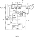
- Fig. 3a is a schematic diagram of a control system for an electric three-phase variable speed motor according to an embodiment.
- the embodiment of Fig. 3a differs from the embodiment of Fig. 2a with respect to the following.
- the fine adjustment module, here denoted 30 comprises a block 30a for calculating a magnitude of a current or power of the motor, a fine adjustment block 30b for determining an optimum compensation current i sd (sc), and a block 30c for adding the optimum compensation current i sd (sc) to the reference d axis current to form an adjusted reference d axis currents i* sd (adj), which when being used as the reference d axis current by the switching signal generation module 18 would cause the motor 12 to operate in a condition wherein the magnitude of a current
- the adjusted reference d axis currents i * sd (adj) is output to the switching signal generation module 18 (
- the switching signal generation module 18 is configured to repeatedly generate switching signals to control the inverter 13 based on the adjusted reference d current i * sd (adj) and the reference q axis current i* sq .
- a latch 30d is provided to hold the output i* sd from the MTPA control block 17b constant while the fine adjustment module 30 determines the optimum compensation current i sd (sc).
- Fig. 3b is a schematic diagram of a portion of the control system of Fig. 3a , wherein the fine adjustment module 30 is shown in greater detail.
- the fine adjustment block 30b may comprise a search signal generation block 32 and a compensation signal generation block 33.
- the fine adjustment module 30 may configured to determine the optimum compensation current in an iterative algorithm based on the perturb and observe principle in a similar manner as has been described in detail with reference to Fig. 2b .
- the output i* sd from the MTPA control block 17b is held constant by the latch 30d during the iteration procedure to find the optimum compensation current. Otherwise the MTPA control block 17b, if left in operation, will try to counter balance the effect from additional reference signal inputs from the fine adjustment module 30.
- a perturbation current i sd (search) and a compensation current i sd (comp) as indicated in Fig. 2b correspond to the perturbation ratio value K(search) and the compensation ratio value K(comp) as disclosed with reference to Fig. 2 b.
- the fine adjustment module 30 is thus configured to determine the optimum compensation current i sd (comp) by means of performing the following algorithm while the output reference d axis current from the MTPA control block 17b is held latched by the latch 30d.
- Step 1 a perturbation or search current signal i sd (search), which is switched on and switched off, is output from the search signal generation block 32 and is added to the reference d axis current i* sd at adder 30c to form a signal on which the switching signal generation module 18 is configured to base repeatedly generated switching signals to control the inverter 13.
- search search
- i sd search current signal
- Step 2 magnitudes of the current
- Step 3 A difference between a magnitude of the current
- Step 4 a compensation current is determined dependent on the above difference and is added to the previously determined compensation current, if any.
- Step 5 the accumulatively added compensation current is added to the signal on which switching signal generation module 18 is configured to base repeatedly generated switching signals to control the inverter 13, or more precisely first added to the search signal i sd (search) via a first adder, and then added to the reference d axis current i* sd by the adder 30c.
- Steps 1-5 are repeated until the difference falls short of a threshold level, at which point the signal generation block 32 switches off the perturbation signal and the optimum compensation current i sd (sc) is obtained as the accumulatively added compensation current.
- the first scheme of modulating K ( Figs. 2a-b ) does not inject a direct step disturbance to the scalar control flux reference.
- the MTPA control block has a definite frequency response, and thus a step variation in K does not cause a step variation in the flux reference.
- the direct step inputs to the reference d axis current may cause spikes in the feedback current unless some filtering of the reference signals is performed. Therefore, appropriate filtering is advisable.
- control arrangements disclosed herein have been described as a sequence of modules and/or blocks for performing various tasks. These modules and/or blocks are preferably implemented as software executed in a microprocessor, a digital control arrangement, or similar device to control an electric motor.
- the present disclosure refers also to control methods for performing, and computer programs for executing, the above disclosed tasks.
Description
- The technical field is generally directed to electric three-phase variable speed motors and to scalar based control thereof.
- Control arrangements for induction motor drives may comprise those, which implement constant V/f control in open loop mode. Such control arrangements may potentially operate the motor drives at enhanced efficiency, by incorporating MTPA (maximum torque per ampere) control in scalar mode. The MTPA control is a model based approach using current angle control. Typically, the stator currents of the motor are resolved into equivalent d and q axis currents and then the d axis current reference is controlled which maximizes motor efficiency.
-
Fig. 1 is a schematic diagram of acontrol system 11 for an electric three-phasevariable speed motor 12 comprising such a scalar basedcontrol arrangement 14 for controlling aninverter 13, which provides power to themotor 12. The control system comprises alsocurrent sensors 15 configured to detect currents of the motor. The control arrangement comprises a d and q axiscurrents determining module 16 configured to determine the d and q axis currents isd, isq based on the detected currents and a reference phase θ*, a lowpass filter block 17a, anMTPA control block 17b, and a switchingsignal generation module 18. - The
current sensors 15 may be configured to detect two ia, ib of the three currents ia, ib ic of the three-phase motor 12. The d and q axiscurrents determining module 16 may in such instance comprise a first current determiningblock 16a configured to determine the three currents ia, ib ic based on the detected currents ia, ib and a second current determiningblock 16b configured to determine the d and q axis currents isd, isq based on the three currents ia, ib ic and a reference phase θ*. - The q axis current isq is input to the low
pass filter block 17a from the d and q axiscurrents determining module 16 and is low pass filtered for control stability in the lowpass filter block 17a to form the reference q axis current i*sq, which is input to the switchingsignal generation module 18. - The d and q axis currents isd, isq are input to the
MTPA control block 18, which is configured to generate a reference d axis current i*sd based on the determined d and q axis currents isd, isq and a ratio value such that the ratio of the d and q axis currents is equal to the ratio value, wherein the ratio value is set to unity. - The switching
signal generation module 18 is configured to generate PWM modulated switching signals to control theinverter 13 based on the reference d and q axis currents i*sd, i*sq. The switchingsignal generation module 18 comprises afirst block 18a, to which the reference d and q axis currents i*sd, i*sq and a reference speed ω* are input. Thefirst block 18a is configured to determine the reference d and q axis voltages u*sd, u*sq from reference d and q axis currents i*sd, i*sq. These voltages are input to asecond block 18b, which is configured to repeatedly generate voltage vectors u*sa, u*sb, u*sc based on the d and q axis voltages u*sd, u*sq and a reference phase θ*.The voltage vectors are PWM modulated in athird block 18c to form PWM modulated switching signals Sa, Sb, Sc, and the PWM modulated switching signals Sa, Sb, Sc are input to theinverter 13. - The second current determining
block 16b of the d and q axiscurrents determining module 16 and thesecond block 18b of the switchingsignal generation module 18 may be implemented using dq-abc transformations. Anintegrator block 19 is configured to integrate the reference speed ω*=2πf*, thereby forming a reference phase θ* by continuously integrating ω*, which is input to the second current determiningblock 16b of the d and q axiscurrents determining module 16 and thesecond block 18b of the switchingsignal generation module 18. - The model based MTPA control approach disclosed above works well if the induction motor magnetization flux is assumed linear function of magnetizing current (constant magnetizing inductance). In reality, this is not true due to the saturation characteristics of motor magnetic flux. At partial speeds and/or low flux levels, the performance is optimum since the motor flux is not saturated at this operation condition. But at nominal speed or when the motor voltage is near the nominal value, due to magnetizing inductance saturation effects, the MTPA control approach as described above does not lead to optimum current operation.
- The present invention is disclosed in
control system claims 1 and 5 andmethod claims 14 and 16.Preferred embodiments are disclosed in dependent claims 2 to 4, 6 to 13, 15 and 17 to 19. - It is an aim of this disclosure to present a control system and a control method for an electric three-phase variable speed motor, which are based on the MTPA control approach, but which can maintain optimum current operation irrespective of operating speed or motor voltage.
- A first aspect refers to a control system for an electric three-phase variable speed motor having a stator and rotor, wherein the control system comprises an inverter for providing power to the electric motor, a scalar based control arrangement for controlling the inverter, and current sensors for measuring motor currents. The control arrangement comprises a d and q axis currents determining module, a filter block, an MTPA control block, a switching signal generation module, and a fine adjustment module.
- The current sensors are configured to repeatedly detect currents of the motor and the d and q axis currents determining module is configured to repeatedly determine d and q axis currents based on the detected currents. The filter block is configured to repeatedly filter the determined q axis current, thereby generating a reference q axis current, and the MTPA control block is configured to repeatedly generate a reference d axis current based on the d and q axis currents and a ratio value such that the ratio of the d and q axis currents is equal to the ratio value, wherein the ratio value is unity. The switching signal generation module is configured to repeatedly generate switching signals to control the inverter based on the reference d and q axis currents.
- At some instant, e.g. when a particular operational condition is met, the fine adjustment module is configured to calculate a magnitude of a current or power of the motor and to determine a compensation ratio value based on the magnitude of a current or power of the motor, which compensation ratio value is added to the ratio value to form an adjusted ratio value, which adjusted ratio value when being used by the MTPA control block would cause the motor to operate in a condition wherein the magnitude of a current or power of the motor is minimized.
- Finally, the MTPA control block is configured to repeatedly generate an adjusted reference d axis current based on the d and q axis currents and the adjusted ratio value such that the ratio of the d and q axis currents is equal to the adjusted ratio value, and the switching signal generation module is configured to repeatedly generate switching signals to control the inverter based on the adjusted reference d axis current and the reference q axis current.
- Hereby, a control system is obtained, which can use the scalar MTPA control approach at unsaturated conditions, and add the proposed fine adjustment when needed, e.g. at saturated conditions or at conditions close to saturation.
- The fine adjustment module may be configured to determine the optimum compensation ratio value in an iterative algorithm based on the perturb and observe principle. That is, a step disturbance signal is injected into the controlling variable and the response, i.e. sign and amplitude, in the controlled variable is monitored. The compensation signal is generated such that the controlled variable is moved to the optimum point where the amplitude of controlled variable is at its minimum (or maximum). This type of control is suitable for the systems which inherently show a minimum point (or maximum point) as the controlling variable is changed across its span. The MTPA based control is a perfect match for such control since the current variation (or efficiency variation) shows a minimum point for variation in the motor flux.
- In one embodiment, the fine adjustment module may be configured to determine the optimum compensation ratio value by means of performing the following algorithm:
- (i) switching on and switching off a perturbation signal, which is added to the ratio value, to form a signal on which the MTPA control block is configured to base a repeatedly generated reference d axis current, on which in turn the switching signal generation module is configured to base repeatedly generated switching signals to control the inverter,
- (ii) determining a difference between a magnitude of a current or power of the motor when the perturbation signal is switched on and a magnitude of a current or power of the motor when the perturbation signal is switched off, and
- (iii) accumulatively adding a compensation ratio value to the signal on which the MTPA control block is configured to base a repeatedly generated reference d axis current, wherein the compensation ratio value is determined dependent on the difference, wherein (i)-(iii) are repeated until the difference falls short of a threshold level.
- The fine adjustment module may configured to switch off the perturbation signal when the difference falls short of a threshold level and the optimum compensation ratio value is obtained as the accumulatively added compensation ratio value.
- A second aspect refers to a control system for an electric three-phase variable speed motor having a stator and rotor, the control system comprising an inverter for providing power to the electric motor, a scalar based control arrangement for controlling the inverter, and current sensors for measuring currents in the motor. The control arrangement comprises a d and q axis currents determining module, a filter block, an MTPA control block, a switching signal generation module, and a fine adjustment module.
- The current sensors are configured to repeatedly detect currents of the motor, the d and q axis currents determining module is configured to repeatedly determine d and q axis currents based on the detected currents; the filter block is configured to repeatedly filter the determined q axis current, thereby generating a reference q axis current, and the MTPA control block is configured to repeatedly generate a reference d axis current based on the d and q axis currents and a ratio value such that the ratio of the d and q axis currents is equal to the ratio value, wherein the ratio value is unity. The switching signal generation module is configured to repeatedly generate switching signals to control the inverter based on the reference d and q axis currents.
- The fine adjustment module is configured to calculate the magnitude of a current or power of the motor and to determine an optimum compensation current based on the calculated magnitude of a current or power of the motor. The optimum compensation current is added to the reference d axis current to form an adjusted reference d axis current, which adjusted reference d axis current when being used by the switching signal generation module would cause the motor to operate in a condition wherein the magnitude of a current or power of the motor is minimized, wherein the switching signal generation module is configured to repeatedly generate switching signals to control the inverter based on the adjusted reference d axis current and the reference q axis current.
- In this aspect, the ratio value, which is used by the MTPA control module, is not fine tuned, but instead a reference current output from the MTPA control block is fine tuned by means of adding a compensation current to the reference d axis current output from the MTPA block, and to feed the switching signal generation module with this sum as the reference d axis current.
- The fine adjustment module may be configured to determine the optimum compensation current in an iterative algorithm based on the perturb and observe principle in a similar manner as disclosed with respect to the first aspect.
- In one embodiment, the fine adjustment module is configured to determine the optimum compensation current by means of performing the following algorithm while the output reference d axis current from the MTPA control block is held latched:
- (i) switching on and switching off a perturbation current signal, which is added to the reference d axis current, to form a signal on which the switching signal generation module is configured to base repeatedly generated switching signals to control the inverter,
- (ii) determining a difference between a magnitude of a current or power of the motor when the perturbation signal is switched on and a magnitude of a current or power of the motor when the perturbation signal is switched off, and
- (iii) accumulatively adding a compensation current to the signal on which switching signal generation module is configured to base repeatedly generated switching signals to control the inverter, wherein the compensation current is determined dependent on the difference, wherein (i)-(iii) are repeated until the difference falls short of a threshold level.
- The fine adjustment module may be configured to switch off the perturbation signal when the difference falls short of a threshold level and the optimum compensation current is obtained as the accumulatively added compensation current.
- The magnitude of a current or power of the motor may be a magnitude of a current of the motor and is calculated as the mean square root of the determined d and q axis currents or from the detected currents.
- Alternatively, the magnitude of a current or power of the motor may be a magnitude of an estimated power of the motor and may be calculated based on reference voltages calculated based on the reference d and q axis currents and (ii) the determined d and q axis currents or the detected currents.
- Yet alternatively, the magnitude of a current or power of the motor is a magnitude of a power of the motor and is calculated based on detected voltages and currents of the motor.
- The control system may be configured to power the stator of an induction motor, and the current sensors may be configured to repeatedly detect stator currents of the motor.
- The fine adjustment module may be configured to be operated at saturated flux operation conditions.
- The fine adjusting may be reset or cancelled when a changed operating condition of the motor, e.g. due to a transient step in torque and/or speed of the motor, is detected, and the fine adjusting may be performed or activated again when a steady state of the motor has been detected.
- A third aspect refers to a control method for an electric three-phase variable speed motor having a stator and rotor, wherein the control method comprises the following steps: (i) receiving repeatedly detected currents of the motor; (ii) repeatedly determining d and q axis currents based on the received currents; (iii) repeatedly filtering the determined q axis current, thereby generating a reference q axis current; (iv) applying an MTPA control scheme in which a reference d axis current is repeatedly generated based on the determined d and q axis currents and a ratio value such that the ratio of the d and q axis currents is equal to the ratio value, wherein the ratio value is unity; (v) repeatedly generating switching signals to control an inverter based on the reference d and q axis currents wherein the inverter is operable to power the motor; (vi) fine adjusting the MTPA control scheme by means of calculating a magnitude of a current or power of the motor and determining an optimum compensation ratio value based on the calculated magnitude of a current or power of the motor, which optimum compensation ratio value is added to the ratio value to form an adjusted ratio value , which when being used in the MTPA control scheme would cause the motor to operate in a condition wherein the magnitude of a current or power of the motor is minimized; (vii) applying the MTPA (maximum torque per ampere) control scheme for repeatedly generating an adjusted reference d axis current based on the determined d and q axis currents and the adjusted ratio value such that the ratio of the d and q axis currents is equal to the adjusted ratio value; and (viii) repeatedly generating switching signals to control the inverter based on the adjusted reference d axis current and the reference q axis current.
- A fourth aspect refers to a control method for an electric three-phase variable speed motor having a stator and rotor, wherein the control method comprises the following steps: (i) receiving repeatedly detected currents of the motor; (ii) repeatedly determining d and q axis currents based on the detected currents; (iii) repeatedly filtering the determined q axis current, thereby generating a reference q axis current; (iv) applying an MTPA control scheme in which a reference d axis current is repeatedly generated based on the determined d and q axis currents and a ratio value such that the ratio of the d and q axis currents is equal to the ratio value, wherein the ratio value is unity; (v)repeatedly generating switching signals to control an inverter based on the reference d and q axis currents wherein the inverter is operable to power the motor; (vi) fine adjusting the MTPA control scheme by means of calculating the magnitude of a current or power of the motor and determining an optimum compensation current based on the calculated magnitude of a current or power of the motor, which optimum compensation current is added to the reference d axis current to form an adjusted reference d axis current, which when being used for generating the switching signals would cause the motor to operate in a condition wherein the magnitude of a current or power of the motor is minimized; and (vi) repeatedly generating switching signals to control the inverter based on the adjusted reference d axis current and the reference q axis current.
- The third to fourth aspects may be modified to disclose any of the additional actions or features as disclosed with reference to the first and second aspects.
- The proposed MTPA based control approach with fine adjustment can easily adapted to existing scalar control. In vast majority of applications, induction motor drives are used in less dynamic applications such as heating, ventilation and air conditioning (HVAC), or in pumping applications. The drives are often operated in scalar control mode with fixed magnetization level which is even left to its rated values wherein the efficiency of the drive is not optimal. In such applications, the proposed MTPA based control approach with fine adjustment will enable to operate these drives at minimum currents or powers, thus increasing the efficiency of the overall drive system.
- Further, the proposed MTPA based control approach can be designed not to cause torque oscillations which are reflected into the motor current and motor speed, not even if slip compensation is active in the scalar control mode.
- Large ripple in the motor current may create implementation issues if the current ripple is larger than the step change in the current resulting from disturbance signal injection, but can be handled by filtering detected motor currents and by allowing sufficient time to pass to enable the motor to stabilize at the adjusted operating point.
- Further characteristics and advantages will be evident from the detailed description of embodiments given hereinafter, and the accompanying
Figs. 1-3 , which are given by way of illustration only. -
-
Fig. 1 is a schematic diagram of a control system for an electric three-phase variable speed motor according to prior art. -
Fig. 2a is a schematic diagram of a control system for an electric three-phase variable speed motor according to an embodiment andFig. 2b is a schematic diagram of a portion of the control system ofFig. 2a . -
Fig. 3a is a schematic diagram of a control system for an electric three-phase variable speed motor according to an embodiment andFig. 3b is a schematic diagram of a portion of the control system ofFig. 3a . - Like numerals refer to like parts throughout the drawings.
-
Fig. 2a is a schematic diagram of acontrol system 11 for an electric three-phasevariable speed motor 12 according to an embodiment. The electric three-phasevariable speed motor 12 may be an induction motor as shown inFig. 2a . Thecontrol system 11 comprises aninverter 13 for providing power to theelectric motor 12, a scalar basedcontrol arrangement 14 for controlling theinverter 13, andcurrent sensors 15 for measuring currents in themotor 12. Theinverter 13 may be connected to the stator of themotor 12. - The
control arrangement 14 comprises a d and q axiscurrents determining module 16, afilter block 17a, an MTPA (maximum torque per ampere)control block 17b, a switchingsignal generation module 18, and afine adjustment module 20. - The
current sensors 15 are configured to repeatedly detect currents, preferably stator currents, of theelectric motor 12 and to forward the detected currents to the d and q axiscurrents determining module 16. - The d and q axis
currents determining module 16 is configured to repeatedly determine d and q axis currents isd, isq based on the detected currents and a reference phase θ*.If thecurrent sensors 15 are configured to detect two ia, ib of the three currents ia, ib ic of the three-phase motor 12, the d and q axiscurrents determining module 16 may comprise a first current determiningblock 16a configured to determine the three currents ia, ib ic based on the detected currents ia, ib and a second current determiningblock 16b configured to determine the d and q axis currents isd, isq based on the three currents ia, ib ic and the reference phase θ*. - The q axis current isq is input to the low
pass filter block 17a from the d and q axiscurrents determining module 16 and is low pass filtered in the lowpass filter block 17a to form the reference q axis current i*sq, which is input to the switchingsignal generation module 18. - The d and q axis currents isd, isq is input to the
MTPA control block 18 from the d and q axiscurrents determining module 16 and is configured to generate a reference d axis current i*sd based on the determined d and q axis currents isd, isq and a ratio value K such that the ratio of the d and q axis currents is equal to the ratio value, wherein the ratio value is set to unity, i.e. K = 1. This is the MTPA control approach neglecting the saturation behaviour of motor magnetizing inductance. - The switching
signal generation module 18 is configured to generate PWM modulated switching signals to control theinverter 13 based on the reference d and q axis currents i*sd, i*sq. The switchingsignal generation module 18 comprises afirst block 18a, to which the reference d and q axis currents i*sd, i*sq and a reference frequency ω* =2πf* are input. Theblock 18a is configured to convert the reference d and q axis currents i*sd, i*sq to reference d and q axis voltages u*sd, u*sq. These voltages are input to asecond block 18b, which is configured to repeatedly generate voltage vectors u*sa, u*sb. u*sc based on the d and q axis voltages u*sd, u*sq and the reference phase θ*. The voltage vectors are PWM modulated in athird block 18c to form PWM modulated switching signals Sa, Sb, Sc, and the PWM modulated switching signals Sa, Sb, Sc are input to theinverter 13. - The second current determining
block 16b of the d and q axiscurrents determining module 16 and thesecond block 18b of the switchingsignal generation module 18 may be implemented using dqo transformations. Anintegrator block 19 is configured to integrate the reference speed (ω*s = 2πf*, thereby forming a reference phase θ*, which is input to the second current determiningblock 16b of the d and q axiscurrents determining module 16 and thesecond block 18b of the switchingsignal generation module 18. - At some operational condition, e.g. a saturated or near saturated flux operation condition, the
fine adjustment module 20 is activated. The fine adjustment module comprises ablock 20a for calculating a magnitude of a current |i| or power P* of the motor, afine adjustment block 20b for determining an optimum compensation ratio value K(sc), and a block 20C for adding the optimum compensation ratio value K(sc) to the ratio value K to form an adjusted ratio value K+ K(sc) = 1 + K(sc), which when being used by the MTPA control module 17 would cause themotor 12 to operate in a condition wherein a magnitude of a current |i| or power P* of the motor is minimized. The adjusted ratio value K+ K(sc) = 1 + K(sc) is then input to theMTPA control block 17b (instead of K = 1). - In response thereto, the
MTPA control block 17b is configured to repeatedly generate an adjusted reference d axis currents i* sd(adj) based on the d and q axis currents isd, isq and the adjusted ratio value i+K(sc) such that the ratio of the d and q axis currents i*sd, i*sq is equal to the adjusted ratio value i+K(sc) and the switchingsignal generation module 18 is configured to repeatedly generate switching signals to control theinverter 13 based on the adjusted reference d current i* sd(adj) and the reference q axis current i*sq. - The magnitude of a current |i| or power P* of the
motor 12 may be a magnitude of the current |i| calculated as the mean square root of the determined d and q axis currents isd, isq as illustrated inFig. 2a . - Alternatively, the magnitude of a current |i| or power P* is a magnitude of an estimated power P* of the
motor 12 and is calculated based on (a) reference voltages calculated based on the reference d and q axis currents (i*sd, i*sq) e.g. by thefirst block 18a of the switchingsignal generation module 18, and (b) the determined d and q axis currents (isd, isq) or the detected currents (ia, ib). - Yet alternatively, the magnitude of a current |i| or power P* is a magnitude of a power of the
motor 12 and is calculated based on detected voltages and currents of themotor 12. - In case a power is used instead, the
block 20a is modified and may have further and/or different inputs in order to calculate a power of the motor in accordance with the above. - The
fine adjustment module 20 may be configured to determine the optimum compensation ratio value K(sc) in an iterative algorithm based on the perturb and observe principle. This will be described below with reference toFig. 2b in the case wherein the magnitude of the current is to be minimized. After smaller modifications of theblock 20a and its inputs, the scheme would work similarly for the optimization of the power. -
Fig. 2b is a schematic diagram of a portion of the control system ofFig. 2a , wherein thefine adjustment module 20 is shown in greater detail. Thefine adjustment block 20b may comprise a searchsignal generation block 22 and a compensationsignal generation block 23. - When the
fine adjustment module 20 is activated, the searchsignal generation block 22 generates a perturbation or search signal K(search). Theblock 20c adds the search signal K(search) to the original ratio value K to form a perturbed ratio value of K + K(search), which is input to theMTPA control block 17b. - The
MTPA control block 17b generates a perturbed reference d axis current based on the determined d and q axis currents isd, isq and the perturbed ratio value K+K(search) such that the ratio of the d and q axis currents is equal to the perturbed ratio value K+K(search). The switchingsignal generation module 18 generates switching signals to control theinverter 13 based on the perturbed reference d and q axis currents. The current 15 measures the resulting currents of the motor and the d and q axiscurrents determining module 16 determines d and q axis currents based on the measured resulting currents and output these to theMTPA control block 17b and theblock 20a of thefine adjustment module 20, which calculates from these the magnitude of the current |i| of the motor. The calculated magnitude is input to the compensationsignal generation block 23, which determines the difference between the calculated magnitudes of the current |i| of the motor when the search signal K(search) is switch on and when it is switched off. Based on the difference a compensation ratio value K(comp) is output from compensationsignal generation block 23 to be added to the ratio value K at 20c via an adder that adds the search signal K(search) and the compensation ratio value K(comp). - The above procedure is repeated until convergence is achieved, i.e. until the difference falls low of a threshold level.
- The search
signal generation block 22 outputs a search signal K(search) which thus is alternately switched off and switched on, e.g. in the form of a square wave signal. - For each switching on and switching off, e.g. each period of the square wave signal, the compensation
signal generation block 23 compares the difference between the calculated magnitude of the current |i| of the motor when the search signal K(search) is switch off and when it is switched off, and determines a compensation ratio value which is accumulatively added to the output. In this manner the ratio value that is input to theMTPA control block 17b is the sum of K and K(sc) wherein K(sc) is the sum of the accumulatively added compensation ratio value K(comp) and the search signal K(search). It is assumed that the search signal K(Search) is small such that typically a number of iterations are required to achieve convergence. - When the difference falls short of the threshold level, the search signal K(Search) is switched off, and the resulting compensation ratio value K(comp) will be equal to K(sc) and is thus the optimum compensation ratio value which is added to the ratio value K(K=1) to form the adjusted ratio value.
- Once the adjusted ratio value is obtained, this is used in the
MTPA control block 17b for the control of theinverter 13 until it can be expected or until it is measured that the operation condition has changed is some manner, e.g. until the speed or motor load torque is changed. - When an operating point is changed (transient step in torque and/or speed), the optimum compensation ratio value K(sc) is reset to default, e.g. zero, and the transient state is continued using the default value of K, i.e. K=1. After the steady state is reached, the above search based compensation algorithm is initiated to determine a new value of optimum compensation ratio value K(sc) .
-
Fig. 3a is a schematic diagram of a control system for an electric three-phase variable speed motor according to an embodiment. The embodiment ofFig. 3a differs from the embodiment ofFig. 2a with respect to the following. The fine adjustment module, here denoted 30 comprises ablock 30a for calculating a magnitude of a current or power of the motor, afine adjustment block 30b for determining an optimum compensation current isd(sc), and ablock 30c for adding the optimum compensation current isd(sc) to the reference d axis current to form an adjusted reference d axis currents i*sd(adj), which when being used as the reference d axis current by the switchingsignal generation module 18 would cause themotor 12 to operate in a condition wherein the magnitude of a current |i| or power P* of the motor is minimized. The adjusted reference d axis currents i* sd(adj) is output to the switching signal generation module 18 (instead of the output i*sd from the MTPA control block). - The switching
signal generation module 18 is configured to repeatedly generate switching signals to control theinverter 13 based on the adjusted reference d current i* sd(adj) and the reference q axis current i*sq. - It shall be appreciated that a
latch 30d is provided to hold the output i*sd from theMTPA control block 17b constant while thefine adjustment module 30 determines the optimum compensation current isd(sc). -
Fig. 3b is a schematic diagram of a portion of the control system ofFig. 3a , wherein thefine adjustment module 30 is shown in greater detail. Thefine adjustment block 30b may comprise a search signal generation block 32 and a compensation signal generation block 33.Thefine adjustment module 30 may configured to determine the optimum compensation current in an iterative algorithm based on the perturb and observe principle in a similar manner as has been described in detail with reference toFig. 2b . - However, the output i*sd from the
MTPA control block 17b is held constant by thelatch 30d during the iteration procedure to find the optimum compensation current. Otherwise theMTPA control block 17b, if left in operation, will try to counter balance the effect from additional reference signal inputs from thefine adjustment module 30. - A perturbation current isd(search) and a compensation current isd(comp) as indicated in
Fig. 2b correspond to the perturbation ratio value K(search) and the compensation ratio value K(comp) as disclosed with reference toFig. 2 b. - The
fine adjustment module 30 is thus configured to determine the optimum compensation current isd(comp) by means of performing the following algorithm while the output reference d axis current from theMTPA control block 17b is held latched by thelatch 30d. - Step 1: a perturbation or search current signal isd(search), which is switched on and switched off, is output from the search signal generation block 32 and is added to the reference d axis current i*sd at
adder 30c to form a signal on which the switchingsignal generation module 18 is configured to base repeatedly generated switching signals to control theinverter 13. - Step 2: magnitudes of the current |i| of the
motor 12 when the search signal isd(search) is switched on and when the perturbation signal isd(search) is switched off is calculated by theblock 30a. - Step 3: A difference between a magnitude of the current |i| of the
motor 12 when the search signal isd(search)is switched on and a magnitude of the current |i| of the motor when the perturbation signal isd(search) is switched off is determined in the compensationsignal generation block 33. - Step 4: a compensation current is determined dependent on the above difference and is added to the previously determined compensation current, if any.
- Step 5: the accumulatively added compensation current is added to the signal on which switching
signal generation module 18 is configured to base repeatedly generated switching signals to control theinverter 13, or more precisely first added to the search signal isd(search) via a first adder, and then added to the reference d axis current i*sd by theadder 30c. - Steps 1-5 are repeated until the difference falls short of a threshold level, at which point the signal generation block 32 switches off the perturbation signal and the optimum compensation current isd(sc) is obtained as the accumulatively added compensation current.
- Although the signal injection and compensation schemes presented above with respect to
Figs. 2a-b , on one hand, and with respect toFigs. 3a-b , on the other hand, may look very similar and operate using the same principle of search signal injection and compensation, there are some basic variations in the way they induce the search signal in the control arrangement. - The first scheme of modulating K (
Figs. 2a-b ) does not inject a direct step disturbance to the scalar control flux reference. The MTPA control block has a definite frequency response, and thus a step variation in K does not cause a step variation in the flux reference. In the second scheme (Figs. 3a-b ), the direct step inputs to the reference d axis current may cause spikes in the feedback current unless some filtering of the reference signals is performed. Therefore, appropriate filtering is advisable. - The control arrangements disclosed herein have been described as a sequence of modules and/or blocks for performing various tasks. These modules and/or blocks are preferably implemented as software executed in a microprocessor, a digital control arrangement, or similar device to control an electric motor.
- The present disclosure refers also to control methods for performing, and computer programs for executing, the above disclosed tasks.
Claims (19)
- A control system (11) for an electric three-phase variable speed motor (12) having a stator and rotor, the control system comprising an inverter (13) for providing power to the electric motor, a scalar based control arrangement (14) for controlling said inverter, and current sensors (15) configured to repeatedly detect currents of the motor, wherein the control arrangement comprises:- a d and q axis currents determining module (16) configured to repeatedly determine d and q axis currents (isd, isq) based on the detected currents;- a filter block (17a) for repeatedly filtering the determined q axis current, thereby generating a reference q axis current (i*sq);- an MTPA (maximum torque per ampere) control block (17b) for repeatedly generating a reference d axis current (i*sd) based on said determined d and q axis currents (isd, isq) and a ratio value such that the ratio of the d and q axis currents is equal to said ratio value, wherein said ratio value is unity, and- a switching signal generation module (18) configured to repeatedly generate switching signals to control said inverter based on said reference d and q axis currents (i*sd, i*sq), characterized in that the control arrangement comprises- a fine adjustment module (20) which is configured to calculate a magnitude of a current (|i|) or power (P*) of the motor and to determine an optimum compensation ratio value (K(sc)) based on the calculated magnitude of a current or power of the motor, which optimum compensation ratio value is added to the ratio value to form an adjusted ratio value (1+ K(sc)), which adjusted ratio value when being used by the MTPA control block would cause the motor to operate in a condition wherein the magnitude of a current or power of the motor is minimized, wherein- the MTPA control block is configured to repeatedly generate an adjusted reference d axis current (i*sd(adj)) based on said determined d and q axis currents (isd, isq) and said adjusted ratio value such that the ratio of the d and q axis currents is equal to said adjusted ratio value; and- the switching signal generation module is configured to repeatedly generate switching signals to control said inverter based on said adjusted reference d axis current.
- The control system of claim 1 wherein the fine adjustment module is configured to determine the optimum compensation ratio value in an iterative algorithm based on the perturb and observe principle.
- The control system of claim 1 or 2 wherein said fine adjustment module is configured to determine said optimum compensation ratio value by means of performing the following algorithm:(i) switching on and switching off a perturbation signal, which is added to the ratio value, to form a signal on which the MTPA control block is configured to base a repeatedly generated reference d axis current, on which in turn the switching signal generation module is configured to base repeatedly generated switching signals to control said inverter,(ii) determining a difference between a magnitude of a current or power of the motor when the perturbation signal is switched on and a magnitude of a current or power of the motor when the perturbation signal is switched off, and(iii) accumulatively adding a compensation ratio value to the signal on which the MTPA control block is configured to base a repeatedly generated reference d axis current, wherein the compensation ratio value is determined dependent on said difference, wherein (i)-(iii) are repeated until said difference falls short of a threshold level.
- The control system of claim 3 wherein said fine adjustment module (20) is configured to switch off the perturbation signal when said difference falls short of a threshold level and said optimum compensation ratio value is obtained as said accumulatively added compensation ratio value.
- A control system (11) for an electric three-phase variable speed motor (12) having a stator and rotor, the control system comprising an inverter (13) for providing power to the electric motor, a scalar based control arrangement (14) for controlling said inverter, and current sensors (15) configured to repeatedly detect currents of the motor, wherein the control arrangement comprises:- a d and q axis currents determining module (16) configured to repeatedly determine d and q axis currents (isd, isq) based on the detected currents;- a filter block (17a) for repeatedly filtering the determined q axis current, thereby generating a reference q axis current (i*sq);- an MTPA (maximum torque per ampere) control block (17b) for repeatedly generating a reference d axis current (i*sd) based on said determined d and q axis currents (isd, isq) and a ratio value such that the ratio of the d and q axis currents is equal to said ratio value, wherein said ratio value is unity, and- a switching signal generation module (18) configured to repeatedly generate switching signals to control said inverter based on said reference d and q axis currents (i*sd, i*sq), characterized in that the control arrangement comprises- a fine adjustment module (30) which is configured to calculate a magnitude of a current (|i|) or power (P*) of the motor and to determine an optimum compensation current (isd (sc)), which is added to the reference d axis current to form an adjusted reference d axis current (i*sd(adj)), which when being used by the switching signal generation module would cause the motor to operate in a condition wherein the magnitude of a current or power of the motor is minimized, wherein- the switching signal generation module is configured to repeatedly generate switching signals to control said inverter based on said adjusted reference d axis current.
- The control system of claim 5 wherein the fine adjustment module is configured to determine the optimum compensation current in an iterative algorithm based on the perturb and observe principle.
- The control system of claim 5 or 6 wherein said fine adjustment module is configured to determine said optimum compensation current by means of performing the following algorithm while the output reference d axis current from the MTPA control block is held latched:(i) switching on and switching off a perturbation current signal, which is added to the reference d axis current, to form a signal on which the switching signal generation module is configured to base repeatedly generated switching signals to control said inverter,(ii) determining a difference between a magnitude of a current or power of the motor when the perturbation signal is switched on and a magnitude of a current or power of the motor when the perturbation signal is switched off, and(iii) accumulatively adding a compensation current to the signal on which switching signal generation module is configured to base repeatedly generated switching signals to control said inverter, wherein the compensation current is determined dependent on said difference, wherein (i)-(iii) are repeated until said difference falls short of a threshold level.
- The control system of claim 7 wherein said fine adjustment module is configured to switch off the perturbation signal when said difference falls short of a threshold level and said optimum compensation current is obtained as said accumulatively added compensation current.
- The control system of any of claims 1-8 wherein said magnitude of a current or power of the motor is a magnitude of a current of the motor and is calculated as the mean square root of the determined d and q axis currents (isd, isq) or from the detected currents (ia, ib).
- The control system of any of claims 1-8 wherein said magnitude of a current or power of the motor is a magnitude of an estimated power of the motor and is calculated based on (i) reference voltages (u*sd, u*sq) calculated based on said reference d and q axis currents (i*sd, i*sq) and (ii) said determined d and q axis currents (isd, isq) or said detected currents (ia, ib).
- The control system any of claims 1-8 wherein said magnitude of a current or power of the motor is a magnitude of a power of the motor and is calculated based on detected voltages and currents of said motor.
- The control system of any of claims 1-11 wherein the control system is configured to power the stator of an induction motor (12), and said current sensors (15) are configured to repeatedly detect stator currents of the motor.
- The control system of any of claims 1-12 wherein the fine adjustment module is configured to be operated at saturated motor flux operation conditions.
- A control method for an electric three-phase variable speed motor (12) having a stator and rotor comprising the steps of:- receiving repeatedly detected currents of the motor;- repeatedly determining d and q axis currents (isd, isq) based on the received currents; repeatedly filtering the determined q axis current, thereby generating a reference q axis current (i*sq);- applying an MTPA (maximum torque per ampere) control scheme in which a reference d axis currents (i*sd) is repeatedly generated based on said determined d and q axis currents (isd, isq) and a ratio value such that the ratio of the d and q axis currents is equal to said ratio value, wherein said ratio value is unity, and- repeatedly generating switching signals to control an inverter based on said reference d and q axis currents (i*sd, i*sq) wherein the inverter is operable to power said motor, characterized by the steps of:- fine adjusting the MTPA control scheme by means of calculating a magnitude of a current (|i|) or power (P*) of the motor and determining an optimum compensation ratio value (K(sc)) based on said calculated magnitude of a current or power of the motor, which optimum compensation ratio value is added to the ratio value to form an adjusted ratio value (1+ K(sc)), which when being used in the MTPA control scheme would cause the motor to operate in a condition wherein the magnitude of a current or power of the motor is minimized;- applying the MTPA (maximum torque per ampere) control scheme for repeatedly generating an adjusted reference d axis current (i*sd(adj)) based on said determined d and q axis currents (isd, isq) and said adjusted ratio value such that the ratio of the reference d and q axis currents is equal to said adjusted ratio value; and- repeatedly generating switching signals to control said inverter based on said adjusted reference d axis current.
- The method of claim 14 wherein the fine adjusting is made by means of performing the following steps:(i) switching on and switching off a perturbation signal, which is added to the ratio value, to form a signal on which the MTPA control scheme is configured to base a repeatedly generated reference d axis current, on which in turn the repeatedly generated switching signals to control said inverter are based,(ii) determining a difference between a magnitude of a current or power of the motor when the perturbation signal is switched on and a magnitude of a current or power of the motor when the perturbation signal is switched off, and(iii) accumulatively adding a compensation ratio value to the signal on which the MTPA control scheme is configured to base a repeatedly generated reference d axis current, wherein the compensation ratio value is determined dependent on said difference, and wherein steps (i)-(iii) are repeated until said difference falls short of a threshold level, thereby obtaining the optimum compensation ratio value as the accumulatively added compensation ratio value.
- A control method for an electric three-phase variable speed motor (12) having a stator and rotor comprising the steps of:- receiving repeatedly detected currents of the motor;- repeatedly determining d and q axis currents (isd, isq) based on the detected currents;- repeatedly filtering the determined q axis current, thereby generating a reference q axis current (i*sq);- applying an MTPA (maximum torque per ampere) control scheme in which a reference d axis current (i*sd) is repeatedly generated based on said determined d and q axis currents (isd, isq) and a ratio value such that the ratio of the reference d and q axis currents is equal to said ratio value, wherein said ratio value is unity, and- repeatedly generating switching signals to control an inverter based on said reference d and q axis currents (i*sd, i*sq) wherein the inverter is operable to power said motor, characterized by the steps of:- fine adjusting the MTPA control scheme by means of calculating a magnitude of a current (|i|) or power (P*) of the motor and determining an optimum compensation current (i(sc)) based on said calculated magnitude of a current or power of the motor, which optimum compensation current is added to the reference d axis current to form an adjusted reference d axis current (i*sd), which when being used for generating the switching signals would cause the motor to operate in a condition wherein the magnitude of a current or power of the motor is minimized; and- repeatedly generating switching signals to control said inverter based on said adjusted reference d axis current.
- The method of claim 16 wherein the fine adjusting is made by means of performing the following steps while the output reference d axis current from the MTPA control block is held latched:(i) switching on and switching off a perturbation current signal, which is added to the reference d axis current, to form a signal on which the repeatedly generated switching signals to control said inverter are based,(ii) determining a difference between a magnitude of a current or power of the motor when the perturbation signal is switched on and a magnitude of a current or power of the motor when the perturbation signal is switched off, and(iii) accumulatively adding a compensation current to the signal on which the repeatedly generated switching signals to control said inverter are based, wherein the compensation current is determined dependent on said difference, and wherein steps (i)-(iii) are repeated until said difference falls short of a threshold level
- The method of any of claims 14-17 wherein said magnitude of a current or power of the motor is (i) a magnitude of a current of the motor and is calculated as the mean square root of the determined d and q axis currents (isd, isq) or from the detected currents (ia, ib); (ii) a magnitude of an estimated power of the motor and is calculated based on (a) reference voltages calculated based on said reference d and q axis currents (i*sd, i*sq) and (b) said determined d and q axis currents (isd, isq) or said detected currents (ia, ib); or (iii) a magnitude of a power of the motor and is calculated based on detected voltages and currents of said motor.
- The method of any of claims 14-18 wherein the fine adjusting is reset when a changed operating condition of the motor, e.g. due to a transient step in torque and/or speed of the motor, is detected, and the fine adjusting is performed again when a steady state of the motor has been detected.
Priority Applications (3)
| Application Number | Priority Date | Filing Date | Title |
|---|---|---|---|
| EP14150005.8A EP2892148B1 (en) | 2014-01-02 | 2014-01-02 | Control system and method for an electric three-phase variable speed motor |
| CN201410837472.2A CN104767448B (en) | 2014-01-02 | 2014-12-29 | Control system and method for electronic three-phase variable speed electric motors, particularly |
| US14/587,859 US9209735B2 (en) | 2014-01-02 | 2014-12-31 | Control system and method for an electric three-phase variable speed motor |
Applications Claiming Priority (1)
| Application Number | Priority Date | Filing Date | Title |
|---|---|---|---|
| EP14150005.8A EP2892148B1 (en) | 2014-01-02 | 2014-01-02 | Control system and method for an electric three-phase variable speed motor |
Publications (2)
| Publication Number | Publication Date |
|---|---|
| EP2892148A1 EP2892148A1 (en) | 2015-07-08 |
| EP2892148B1 true EP2892148B1 (en) | 2021-09-22 |
Family
ID=49885127
Family Applications (1)
| Application Number | Title | Priority Date | Filing Date |
|---|---|---|---|
| EP14150005.8A Active EP2892148B1 (en) | 2014-01-02 | 2014-01-02 | Control system and method for an electric three-phase variable speed motor |
Country Status (3)
| Country | Link |
|---|---|
| US (1) | US9209735B2 (en) |
| EP (1) | EP2892148B1 (en) |
| CN (1) | CN104767448B (en) |
Families Citing this family (17)
| Publication number | Priority date | Publication date | Assignee | Title |
|---|---|---|---|---|
| WO2017037496A1 (en) * | 2015-08-29 | 2017-03-09 | Abb Technology Ltd. | System having electrical machine and controller |
| US9995119B2 (en) | 2015-11-16 | 2018-06-12 | Ge Oil & Gas Esp, Inc. | Electric submersible pumping system with permanent magnet motor |
| CN106059427A (en) * | 2016-07-01 | 2016-10-26 | 深圳市海浦蒙特科技有限公司 | Permanent magnet synchronous motor control method and system |
| US11359470B2 (en) | 2016-09-30 | 2022-06-14 | Baker Hughes Oilfield Operations, Llc | Systems and methods for optimizing an efficiency of a variable frequency drive |
| US10778124B2 (en) | 2017-02-24 | 2020-09-15 | General Electric Company | Integrated monitoring of an electric motor assembly |
| CN108448976B (en) * | 2018-03-21 | 2019-09-27 | 华中科技大学 | A kind of permanent magnet synchronous motor maximum torque per ampere control device |
| CN108736787B (en) * | 2018-05-30 | 2019-11-05 | 中车青岛四方车辆研究所有限公司 | Permanent-magnet synchronous traction drive control system and method |
| CN108880380B (en) * | 2018-07-05 | 2021-07-20 | 江苏大学 | Optimal torque angle control system of built-in permanent magnet synchronous motor |
| EP3641128A1 (en) | 2018-10-17 | 2020-04-22 | ABB Schweiz AG | Method of controlling a motor |
| CN110474585B (en) * | 2019-08-21 | 2021-01-01 | 中车永济电机有限公司 | Control modulation method for high-power direct-drive permanent magnet synchronous motor |
| CN110518849B (en) * | 2019-09-04 | 2020-12-01 | 北京理工大学 | Permanent magnet synchronous motor maximum torque current ratio voltage vector directional control method |
| DE102020203488A1 (en) * | 2020-03-18 | 2021-09-23 | BSH Hausgeräte GmbH | Household appliance and method for operating a household appliance |
| DE102020203489A1 (en) * | 2020-03-18 | 2021-09-23 | BSH Hausgeräte GmbH | Household appliance and method for operating a household appliance |
| CN112740537B (en) * | 2020-12-24 | 2023-02-17 | 深圳市英威腾电气股份有限公司 | MTPA control method, device, system and equipment of permanent magnet synchronous motor |
| CN113236541B (en) * | 2021-05-20 | 2023-03-07 | 广东美芝制冷设备有限公司 | Compressor control method, device, storage medium and apparatus |
| US11539283B1 (en) * | 2021-06-04 | 2022-12-27 | Rockwell Automation Technologies, Inc. | System and method for reducing delay in the modulation of a multi-phase output voltage from an inverter |
| US11671037B1 (en) * | 2022-05-05 | 2023-06-06 | Rockwell Automation Technologies, Inc. | Efficiency optimization of maximum torque per amps control for synchronous motors |
Family Cites Families (18)
| Publication number | Priority date | Publication date | Assignee | Title |
|---|---|---|---|---|
| JPH07118956B2 (en) | 1987-02-17 | 1995-12-18 | 株式会社明電舎 | Vector controller |
| JPH09219999A (en) | 1996-02-15 | 1997-08-19 | Meidensha Corp | Variable speed drive device |
| US6936991B2 (en) * | 2002-06-03 | 2005-08-30 | Ballard Power Systems Corporation | Method and apparatus for motor control |
| US6924617B2 (en) | 2003-06-23 | 2005-08-02 | General Motors Corporation | Position sensorless control algorithm for AC machine |
| US7023168B1 (en) * | 2004-09-13 | 2006-04-04 | General Motors Corporation | Field weakening motor control system and method |
| US7348756B2 (en) * | 2004-11-30 | 2008-03-25 | Honeywell International Inc. | Advanced current control method and apparatus for a motor drive system |
| US8228016B2 (en) * | 2007-07-27 | 2012-07-24 | GM Global Technology Operations LLC | Gain adjustment to improve torque linearity in a field weakening region |
| GB2465379A (en) * | 2008-11-17 | 2010-05-19 | Technelec Ltd | Controller for electrical machines |
| JP5235912B2 (en) | 2010-01-14 | 2013-07-10 | 三菱電機株式会社 | Reluctance motor |
| US8648562B2 (en) * | 2010-08-09 | 2014-02-11 | Thomas A. Lipo | Single power supply dual converter open-winding machine drive |
| KR101761740B1 (en) * | 2011-02-01 | 2017-07-26 | 삼성전자 주식회사 | Apparatus for estimating inductance of permanent magnet synchronous motor and method the same |
| US8410737B2 (en) * | 2011-02-28 | 2013-04-02 | Deere & Company | Device and method for generating an initial controller lookup table for an IPM machine |
| US8779702B2 (en) * | 2011-06-06 | 2014-07-15 | Caterpillar Inc. | Motor control system implementing field weakening |
| KR101562418B1 (en) * | 2011-07-05 | 2015-10-22 | 엘에스산전 주식회사 | Apparatus for operating interior permanent magnet synchronous machine |
| KR101298973B1 (en) | 2011-10-17 | 2013-08-23 | 한국전기연구원 | Complex condition diagnosis device and method for induction motor using on-line technique |
| US8593088B2 (en) * | 2012-01-13 | 2013-11-26 | Chrysler Group Llc | Method and system for controlling an electric motor for a vehicle |
| US9000694B2 (en) * | 2012-03-23 | 2015-04-07 | Fanuc Corporation | Synchronous motor control apparatus |
| KR101827000B1 (en) * | 2012-06-12 | 2018-02-07 | 현대자동차주식회사 | Method for controlling interior permanent magnet synchronous motor |
-
2014
- 2014-01-02 EP EP14150005.8A patent/EP2892148B1/en active Active
- 2014-12-29 CN CN201410837472.2A patent/CN104767448B/en active Active
- 2014-12-31 US US14/587,859 patent/US9209735B2/en active Active
Also Published As
| Publication number | Publication date |
|---|---|
| CN104767448A (en) | 2015-07-08 |
| CN104767448B (en) | 2018-04-17 |
| EP2892148A1 (en) | 2015-07-08 |
| US9209735B2 (en) | 2015-12-08 |
| US20150188474A1 (en) | 2015-07-02 |
Similar Documents
| Publication | Publication Date | Title |
|---|---|---|
| EP2892148B1 (en) | Control system and method for an electric three-phase variable speed motor | |
| Alsofyani et al. | Dynamic hysteresis torque band for improving the performance of lookup-table-based DTC of induction machines | |
| Shin et al. | Anti-windup PID controller with integral state predictor for variable-speed motor drives | |
| Bolognani et al. | Flux-weakening in IPM motor drives: Comparison of state-of-art algorithms and a novel proposal for controller design | |
| Lascu et al. | Super-twisting sliding mode direct torque contol of induction machine drives | |
| US9407178B2 (en) | Method and apparatus for controlling an electric machine in a six-step mode | |
| Ribeiro et al. | A sliding-mode voltage regulator for salient pole synchronous generator | |
| Song et al. | Observer-based predictive vector-resonant current control of permanent magnet synchronous machines | |
| Song et al. | Active damping stabilization for high-speed BLDCM drive system based on band-pass filter | |
| Konstantopoulos et al. | Bounded nonlinear stabilizing speed regulators for VSI-fed induction motors in field-oriented operation | |
| Zhang et al. | Indirect field-oriented control of induction machines based on synergetic control theory | |
| Bolognani et al. | Adaptive flux-weakening controller for IPMSM drives | |
| Hemavathy et al. | Comparison of indirect vector control and direct torque control applied to Induction Motor drive | |
| Alsofyani et al. | Improved EKF-based direct torque control at the start-up using constant switching frequency | |
| Nisha et al. | Sensorless field oriented control of SVM inverter fed induction machine in field weakening region using sliding mode observer | |
| Merzoug et al. | Nonlinear backstepping control of permanent magnet synchronous motor (PMSM) | |
| Bolognani et al. | Optimal voltage feed-back flux-weakening control of IPMSM | |
| Patel et al. | Development of a nonlinear loss minimization control of an IPMSM drive with flux estimation | |
| Zuo et al. | Two-degree-of-freedom quasi-pir controller for smooth speed control of permanent magnet vernier machine | |
| CN111418144A (en) | Motor control method and motor control device | |
| Pavuluri et al. | Field Oriented Control of Induction Motors Using Symmetrical Optimum Method with Applications in Hybrid Electric Vehicles | |
| Ali et al. | Design of a speed controller using extended Kalman filter for PMSM | |
| Prashanth et al. | Parameter estimation of PMSM using adaptive backstepping technique | |
| George et al. | Speed Control of PMSM using Backstepping Method | |
| Islam et al. | Field oriented rectangular current regulated PWM control of permanent magnet brushless DC motor |
Legal Events
| Date | Code | Title | Description |
|---|---|---|---|
| PUAI | Public reference made under article 153(3) epc to a published international application that has entered the european phase |
Free format text: ORIGINAL CODE: 0009012 |
|
| 17P | Request for examination filed |
Effective date: 20140102 |
|
| AK | Designated contracting states |
Kind code of ref document: A1 Designated state(s): AL AT BE BG CH CY CZ DE DK EE ES FI FR GB GR HR HU IE IS IT LI LT LU LV MC MK MT NL NO PL PT RO RS SE SI SK SM TR |
|
| AX | Request for extension of the european patent |
Extension state: BA ME |
|
| R17P | Request for examination filed (corrected) |
Effective date: 20160108 |
|
| RBV | Designated contracting states (corrected) |
Designated state(s): AL AT BE BG CH CY CZ DE DK EE ES FI FR GB GR HR HU IE IS IT LI LT LU LV MC MK MT NL NO PL PT RO RS SE SI SK SM TR |
|
| RAP1 | Party data changed (applicant data changed or rights of an application transferred) |
Owner name: ABB SCHWEIZ AG |
|
| STAA | Information on the status of an ep patent application or granted ep patent |
Free format text: STATUS: EXAMINATION IS IN PROGRESS |
|
| 17Q | First examination report despatched |
Effective date: 20180104 |
|
| REG | Reference to a national code |
Ref country code: DE Ref legal event code: R079 Ref document number: 602014080225 Country of ref document: DE Free format text: PREVIOUS MAIN CLASS: H02P0021000000 Ipc: H02P0021140000 |
|
| RIC1 | Information provided on ipc code assigned before grant |
Ipc: H02P 21/14 20160101AFI20201118BHEP Ipc: H02P 21/00 20160101ALI20201118BHEP |
|
| GRAP | Despatch of communication of intention to grant a patent |
Free format text: ORIGINAL CODE: EPIDOSNIGR1 |
|
| STAA | Information on the status of an ep patent application or granted ep patent |
Free format text: STATUS: GRANT OF PATENT IS INTENDED |
|
| INTG | Intention to grant announced |
Effective date: 20210114 |
|
| GRAJ | Information related to disapproval of communication of intention to grant by the applicant or resumption of examination proceedings by the epo deleted |
Free format text: ORIGINAL CODE: EPIDOSDIGR1 |
|
| STAA | Information on the status of an ep patent application or granted ep patent |
Free format text: STATUS: EXAMINATION IS IN PROGRESS |
|
| RAP3 | Party data changed (applicant data changed or rights of an application transferred) |
Owner name: ABB SCHWEIZ AG |
|
| INTC | Intention to grant announced (deleted) | ||
| GRAS | Grant fee paid |
Free format text: ORIGINAL CODE: EPIDOSNIGR3 |
|
| STAA | Information on the status of an ep patent application or granted ep patent |
Free format text: STATUS: GRANT OF PATENT IS INTENDED |
|
| GRAP | Despatch of communication of intention to grant a patent |
Free format text: ORIGINAL CODE: EPIDOSNIGR1 |
|
| INTG | Intention to grant announced |
Effective date: 20210624 |
|
| GRAA | (expected) grant |
Free format text: ORIGINAL CODE: 0009210 |
|
| STAA | Information on the status of an ep patent application or granted ep patent |
Free format text: STATUS: THE PATENT HAS BEEN GRANTED |
|
| AK | Designated contracting states |
Kind code of ref document: B1 Designated state(s): AL AT BE BG CH CY CZ DE DK EE ES FI FR GB GR HR HU IE IS IT LI LT LU LV MC MK MT NL NO PL PT RO RS SE SI SK SM TR |
|
| REG | Reference to a national code |
Ref country code: GB Ref legal event code: FG4D |
|
| REG | Reference to a national code |
Ref country code: IE Ref legal event code: FG4D |
|
| REG | Reference to a national code |
Ref country code: DE Ref legal event code: R096 Ref document number: 602014080225 Country of ref document: DE |
|
| REG | Reference to a national code |
Ref country code: CH Ref legal event code: EP Ref country code: AT Ref legal event code: REF Ref document number: 1433097 Country of ref document: AT Kind code of ref document: T Effective date: 20211015 |
|
| REG | Reference to a national code |
Ref country code: LT Ref legal event code: MG9D |
|
| REG | Reference to a national code |
Ref country code: NL Ref legal event code: MP Effective date: 20210922 |
|
| PG25 | Lapsed in a contracting state [announced via postgrant information from national office to epo] |
Ref country code: BG Free format text: LAPSE BECAUSE OF FAILURE TO SUBMIT A TRANSLATION OF THE DESCRIPTION OR TO PAY THE FEE WITHIN THE PRESCRIBED TIME-LIMIT Effective date: 20211222 Ref country code: LT Free format text: LAPSE BECAUSE OF FAILURE TO SUBMIT A TRANSLATION OF THE DESCRIPTION OR TO PAY THE FEE WITHIN THE PRESCRIBED TIME-LIMIT Effective date: 20210922 Ref country code: FI Free format text: LAPSE BECAUSE OF FAILURE TO SUBMIT A TRANSLATION OF THE DESCRIPTION OR TO PAY THE FEE WITHIN THE PRESCRIBED TIME-LIMIT Effective date: 20210922 Ref country code: NO Free format text: LAPSE BECAUSE OF FAILURE TO SUBMIT A TRANSLATION OF THE DESCRIPTION OR TO PAY THE FEE WITHIN THE PRESCRIBED TIME-LIMIT Effective date: 20211222 Ref country code: HR Free format text: LAPSE BECAUSE OF FAILURE TO SUBMIT A TRANSLATION OF THE DESCRIPTION OR TO PAY THE FEE WITHIN THE PRESCRIBED TIME-LIMIT Effective date: 20210922 Ref country code: RS Free format text: LAPSE BECAUSE OF FAILURE TO SUBMIT A TRANSLATION OF THE DESCRIPTION OR TO PAY THE FEE WITHIN THE PRESCRIBED TIME-LIMIT Effective date: 20210922 Ref country code: SE Free format text: LAPSE BECAUSE OF FAILURE TO SUBMIT A TRANSLATION OF THE DESCRIPTION OR TO PAY THE FEE WITHIN THE PRESCRIBED TIME-LIMIT Effective date: 20210922 |
|
| REG | Reference to a national code |
Ref country code: AT Ref legal event code: MK05 Ref document number: 1433097 Country of ref document: AT Kind code of ref document: T Effective date: 20210922 |
|
| PG25 | Lapsed in a contracting state [announced via postgrant information from national office to epo] |
Ref country code: LV Free format text: LAPSE BECAUSE OF FAILURE TO SUBMIT A TRANSLATION OF THE DESCRIPTION OR TO PAY THE FEE WITHIN THE PRESCRIBED TIME-LIMIT Effective date: 20210922 Ref country code: GR Free format text: LAPSE BECAUSE OF FAILURE TO SUBMIT A TRANSLATION OF THE DESCRIPTION OR TO PAY THE FEE WITHIN THE PRESCRIBED TIME-LIMIT Effective date: 20211223 |
|
| PG25 | Lapsed in a contracting state [announced via postgrant information from national office to epo] |
Ref country code: AT Free format text: LAPSE BECAUSE OF FAILURE TO SUBMIT A TRANSLATION OF THE DESCRIPTION OR TO PAY THE FEE WITHIN THE PRESCRIBED TIME-LIMIT Effective date: 20210922 |
|
| PG25 | Lapsed in a contracting state [announced via postgrant information from national office to epo] |
Ref country code: IS Free format text: LAPSE BECAUSE OF FAILURE TO SUBMIT A TRANSLATION OF THE DESCRIPTION OR TO PAY THE FEE WITHIN THE PRESCRIBED TIME-LIMIT Effective date: 20220122 Ref country code: SK Free format text: LAPSE BECAUSE OF FAILURE TO SUBMIT A TRANSLATION OF THE DESCRIPTION OR TO PAY THE FEE WITHIN THE PRESCRIBED TIME-LIMIT Effective date: 20210922 Ref country code: RO Free format text: LAPSE BECAUSE OF FAILURE TO SUBMIT A TRANSLATION OF THE DESCRIPTION OR TO PAY THE FEE WITHIN THE PRESCRIBED TIME-LIMIT Effective date: 20210922 Ref country code: PT Free format text: LAPSE BECAUSE OF FAILURE TO SUBMIT A TRANSLATION OF THE DESCRIPTION OR TO PAY THE FEE WITHIN THE PRESCRIBED TIME-LIMIT Effective date: 20220124 Ref country code: PL Free format text: LAPSE BECAUSE OF FAILURE TO SUBMIT A TRANSLATION OF THE DESCRIPTION OR TO PAY THE FEE WITHIN THE PRESCRIBED TIME-LIMIT Effective date: 20210922 Ref country code: NL Free format text: LAPSE BECAUSE OF FAILURE TO SUBMIT A TRANSLATION OF THE DESCRIPTION OR TO PAY THE FEE WITHIN THE PRESCRIBED TIME-LIMIT Effective date: 20210922 Ref country code: ES Free format text: LAPSE BECAUSE OF FAILURE TO SUBMIT A TRANSLATION OF THE DESCRIPTION OR TO PAY THE FEE WITHIN THE PRESCRIBED TIME-LIMIT Effective date: 20210922 Ref country code: EE Free format text: LAPSE BECAUSE OF FAILURE TO SUBMIT A TRANSLATION OF THE DESCRIPTION OR TO PAY THE FEE WITHIN THE PRESCRIBED TIME-LIMIT Effective date: 20210922 Ref country code: CZ Free format text: LAPSE BECAUSE OF FAILURE TO SUBMIT A TRANSLATION OF THE DESCRIPTION OR TO PAY THE FEE WITHIN THE PRESCRIBED TIME-LIMIT Effective date: 20210922 Ref country code: AL Free format text: LAPSE BECAUSE OF FAILURE TO SUBMIT A TRANSLATION OF THE DESCRIPTION OR TO PAY THE FEE WITHIN THE PRESCRIBED TIME-LIMIT Effective date: 20210922 |
|
| REG | Reference to a national code |
Ref country code: DE Ref legal event code: R097 Ref document number: 602014080225 Country of ref document: DE |
|
| PG25 | Lapsed in a contracting state [announced via postgrant information from national office to epo] |
Ref country code: DK Free format text: LAPSE BECAUSE OF FAILURE TO SUBMIT A TRANSLATION OF THE DESCRIPTION OR TO PAY THE FEE WITHIN THE PRESCRIBED TIME-LIMIT Effective date: 20210922 |
|
| PLBE | No opposition filed within time limit |
Free format text: ORIGINAL CODE: 0009261 |
|
| STAA | Information on the status of an ep patent application or granted ep patent |
Free format text: STATUS: NO OPPOSITION FILED WITHIN TIME LIMIT |
|
| 26N | No opposition filed |
Effective date: 20220623 |
|
| PG25 | Lapsed in a contracting state [announced via postgrant information from national office to epo] |
Ref country code: MC Free format text: LAPSE BECAUSE OF FAILURE TO SUBMIT A TRANSLATION OF THE DESCRIPTION OR TO PAY THE FEE WITHIN THE PRESCRIBED TIME-LIMIT Effective date: 20210922 |
|
| REG | Reference to a national code |
Ref country code: CH Ref legal event code: PL |
|
| REG | Reference to a national code |
Ref country code: BE Ref legal event code: MM Effective date: 20220131 |
|
| PG25 | Lapsed in a contracting state [announced via postgrant information from national office to epo] |
Ref country code: LU Free format text: LAPSE BECAUSE OF NON-PAYMENT OF DUE FEES Effective date: 20220102 |
|
| PG25 | Lapsed in a contracting state [announced via postgrant information from national office to epo] |
Ref country code: SI Free format text: LAPSE BECAUSE OF FAILURE TO SUBMIT A TRANSLATION OF THE DESCRIPTION OR TO PAY THE FEE WITHIN THE PRESCRIBED TIME-LIMIT Effective date: 20210922 Ref country code: BE Free format text: LAPSE BECAUSE OF NON-PAYMENT OF DUE FEES Effective date: 20220131 |
|
| PG25 | Lapsed in a contracting state [announced via postgrant information from national office to epo] |
Ref country code: LI Free format text: LAPSE BECAUSE OF NON-PAYMENT OF DUE FEES Effective date: 20220131 Ref country code: CH Free format text: LAPSE BECAUSE OF NON-PAYMENT OF DUE FEES Effective date: 20220131 |
|
| PG25 | Lapsed in a contracting state [announced via postgrant information from national office to epo] |
Ref country code: IT Free format text: LAPSE BECAUSE OF FAILURE TO SUBMIT A TRANSLATION OF THE DESCRIPTION OR TO PAY THE FEE WITHIN THE PRESCRIBED TIME-LIMIT Effective date: 20210922 Ref country code: IE Free format text: LAPSE BECAUSE OF NON-PAYMENT OF DUE FEES Effective date: 20220102 |
|
| PGFP | Annual fee paid to national office [announced via postgrant information from national office to epo] |
Ref country code: FR Payment date: 20230124 Year of fee payment: 10 |
|
| PGFP | Annual fee paid to national office [announced via postgrant information from national office to epo] |
Ref country code: GB Payment date: 20230119 Year of fee payment: 10 Ref country code: DE Payment date: 20230123 Year of fee payment: 10 |
|
| PG25 | Lapsed in a contracting state [announced via postgrant information from national office to epo] |
Ref country code: HU Free format text: LAPSE BECAUSE OF FAILURE TO SUBMIT A TRANSLATION OF THE DESCRIPTION OR TO PAY THE FEE WITHIN THE PRESCRIBED TIME-LIMIT; INVALID AB INITIO Effective date: 20140102 |