EP3882473A1 - Click-connection - Google Patents
Click-connection Download PDFInfo
- Publication number
- EP3882473A1 EP3882473A1 EP21162759.1A EP21162759A EP3882473A1 EP 3882473 A1 EP3882473 A1 EP 3882473A1 EP 21162759 A EP21162759 A EP 21162759A EP 3882473 A1 EP3882473 A1 EP 3882473A1
- Authority
- EP
- European Patent Office
- Prior art keywords
- groove
- retaining
- retaining elements
- sides
- fittings
- Prior art date
- Legal status (The legal status is an assumption and is not a legal conclusion. Google has not performed a legal analysis and makes no representation as to the accuracy of the status listed.)
- Granted
Links
- 239000000463 material Substances 0.000 claims description 5
- 238000005452 bending Methods 0.000 claims description 3
- 239000005060 rubber Substances 0.000 claims description 3
- 239000004033 plastic Substances 0.000 claims description 2
- 239000002023 wood Substances 0.000 claims description 2
- 239000002184 metal Substances 0.000 claims 1
- 238000004064 recycling Methods 0.000 claims 1
- 210000001331 nose Anatomy 0.000 description 5
- 125000006850 spacer group Chemical group 0.000 description 5
- 239000003381 stabilizer Substances 0.000 description 5
- 238000003780 insertion Methods 0.000 description 4
- 230000037431 insertion Effects 0.000 description 4
- 230000014759 maintenance of location Effects 0.000 description 4
- 238000010276 construction Methods 0.000 description 3
- 229910003460 diamond Inorganic materials 0.000 description 2
- 239000010432 diamond Substances 0.000 description 2
- 238000003801 milling Methods 0.000 description 2
- XAGFODPZIPBFFR-UHFFFAOYSA-N aluminium Chemical compound [Al] XAGFODPZIPBFFR-UHFFFAOYSA-N 0.000 description 1
- 229910052782 aluminium Inorganic materials 0.000 description 1
- 230000008602 contraction Effects 0.000 description 1
- 230000006378 damage Effects 0.000 description 1
- 238000005553 drilling Methods 0.000 description 1
- 230000000694 effects Effects 0.000 description 1
- 239000003000 extruded plastic Substances 0.000 description 1
- 230000013011 mating Effects 0.000 description 1
- 230000008018 melting Effects 0.000 description 1
- 238000002844 melting Methods 0.000 description 1
- 239000002991 molded plastic Substances 0.000 description 1
- 239000007787 solid Substances 0.000 description 1
- 239000011343 solid material Substances 0.000 description 1
Images


Classifications
-
- F—MECHANICAL ENGINEERING; LIGHTING; HEATING; WEAPONS; BLASTING
- F16—ENGINEERING ELEMENTS AND UNITS; GENERAL MEASURES FOR PRODUCING AND MAINTAINING EFFECTIVE FUNCTIONING OF MACHINES OR INSTALLATIONS; THERMAL INSULATION IN GENERAL
- F16B—DEVICES FOR FASTENING OR SECURING CONSTRUCTIONAL ELEMENTS OR MACHINE PARTS TOGETHER, e.g. NAILS, BOLTS, CIRCLIPS, CLAMPS, CLIPS OR WEDGES; JOINTS OR JOINTING
- F16B5/00—Joining sheets or plates, e.g. panels, to one another or to strips or bars parallel to them
- F16B5/0004—Joining sheets, plates or panels in abutting relationship
- F16B5/0008—Joining sheets, plates or panels in abutting relationship by moving the sheets, plates or panels substantially in their own plane, perpendicular to the abutting edge
- F16B5/002—Joining sheets, plates or panels in abutting relationship by moving the sheets, plates or panels substantially in their own plane, perpendicular to the abutting edge both sheets, plates or panels having a groove, e.g. with strip-type connector
-
- F—MECHANICAL ENGINEERING; LIGHTING; HEATING; WEAPONS; BLASTING
- F16—ENGINEERING ELEMENTS AND UNITS; GENERAL MEASURES FOR PRODUCING AND MAINTAINING EFFECTIVE FUNCTIONING OF MACHINES OR INSTALLATIONS; THERMAL INSULATION IN GENERAL
- F16B—DEVICES FOR FASTENING OR SECURING CONSTRUCTIONAL ELEMENTS OR MACHINE PARTS TOGETHER, e.g. NAILS, BOLTS, CIRCLIPS, CLAMPS, CLIPS OR WEDGES; JOINTS OR JOINTING
- F16B17/00—Connecting constructional elements or machine parts by a part of or on one member entering a hole in the other and involving plastic deformation
-
- F—MECHANICAL ENGINEERING; LIGHTING; HEATING; WEAPONS; BLASTING
- F16—ENGINEERING ELEMENTS AND UNITS; GENERAL MEASURES FOR PRODUCING AND MAINTAINING EFFECTIVE FUNCTIONING OF MACHINES OR INSTALLATIONS; THERMAL INSULATION IN GENERAL
- F16B—DEVICES FOR FASTENING OR SECURING CONSTRUCTIONAL ELEMENTS OR MACHINE PARTS TOGETHER, e.g. NAILS, BOLTS, CIRCLIPS, CLAMPS, CLIPS OR WEDGES; JOINTS OR JOINTING
- F16B5/00—Joining sheets or plates, e.g. panels, to one another or to strips or bars parallel to them
- F16B5/06—Joining sheets or plates, e.g. panels, to one another or to strips or bars parallel to them by means of clamps or clips
- F16B5/0607—Joining sheets or plates, e.g. panels, to one another or to strips or bars parallel to them by means of clamps or clips joining sheets or plates to each other
- F16B5/0621—Joining sheets or plates, e.g. panels, to one another or to strips or bars parallel to them by means of clamps or clips joining sheets or plates to each other in parallel relationship
- F16B5/0664—Joining sheets or plates, e.g. panels, to one another or to strips or bars parallel to them by means of clamps or clips joining sheets or plates to each other in parallel relationship at least one of the sheets or plates having integrally formed or integrally connected snap-in-features
-
- F—MECHANICAL ENGINEERING; LIGHTING; HEATING; WEAPONS; BLASTING
- F16—ENGINEERING ELEMENTS AND UNITS; GENERAL MEASURES FOR PRODUCING AND MAINTAINING EFFECTIVE FUNCTIONING OF MACHINES OR INSTALLATIONS; THERMAL INSULATION IN GENERAL
- F16B—DEVICES FOR FASTENING OR SECURING CONSTRUCTIONAL ELEMENTS OR MACHINE PARTS TOGETHER, e.g. NAILS, BOLTS, CIRCLIPS, CLAMPS, CLIPS OR WEDGES; JOINTS OR JOINTING
- F16B5/00—Joining sheets or plates, e.g. panels, to one another or to strips or bars parallel to them
- F16B5/07—Joining sheets or plates, e.g. panels, to one another or to strips or bars parallel to them by means of multiple interengaging protrusions on the surfaces, e.g. hooks, coils
-
- F—MECHANICAL ENGINEERING; LIGHTING; HEATING; WEAPONS; BLASTING
- F16—ENGINEERING ELEMENTS AND UNITS; GENERAL MEASURES FOR PRODUCING AND MAINTAINING EFFECTIVE FUNCTIONING OF MACHINES OR INSTALLATIONS; THERMAL INSULATION IN GENERAL
- F16B—DEVICES FOR FASTENING OR SECURING CONSTRUCTIONAL ELEMENTS OR MACHINE PARTS TOGETHER, e.g. NAILS, BOLTS, CIRCLIPS, CLAMPS, CLIPS OR WEDGES; JOINTS OR JOINTING
- F16B7/00—Connections of rods or tubes, e.g. of non-circular section, mutually, including resilient connections
- F16B7/04—Clamping or clipping connections
- F16B7/0433—Clamping or clipping connections for rods or tubes being in parallel relationship
Abstract
Die Klick-Verbindung ist für zwei zu verbindende Formstücke (1,2) bestimmt. Die beiden Formstücke (1,2) sind identisch ausgeformt, indem sie auf der Seite mit der zu verbindenden Fläche eine Nut (3) aufweisen, innerhalb welcher auf beiden Flankenseiten (4, 5) der Nut (3) Rückhalteflächen ausgeformt sind. Fest oder lösbar mit dem Nutboden verbundene Rückhalte-Elemente (8) überragen die Nut (3) nach aussen und im Bereich ihrer Spitze weisen sie beidseits Hinterschnitt-Flächen (11) als Widerhaken oder Rückhalteflächen auf. Nach hinten laufen sie beidseits in federnde Flügel (12) aus. Damit lassen sich zwei aus den Nuten (3) herausragende Rückhalte-Elemente (8) von gegeneinander hin gerichteten Formstücken (1,2) durch überlappendes Ineinanderschieben der beiden Rückhalte-Elemente (8) unter elastischem Nachgeben der Flügel (12) zu einer formschlüssigen Verbindung zusammenklicken. Dabei verrasten die Rückhalte-Elemente (8) mit ihren Hinterschnitt-Flächen (11) mit den Rückhalteflächen (6) in den Nuten der jeweils gegenüberliegenden Formstücke (1, 2), sodass eine satte, auf Zugkraft belastbare Verbindung entsteht.The click connection is intended for two fittings to be connected (1,2). The two shaped pieces (1,2) are shaped identically in that they have a groove (3) on the side with the surface to be connected, within which retaining surfaces are formed on both flank sides (4, 5) of the groove (3). Retaining elements (8) connected fixedly or detachably to the groove base protrude outwardly beyond the groove (3) and in the region of their tip they have undercut surfaces (11) on both sides as barbs or retaining surfaces. To the rear, they run out into resilient wings (12) on both sides. This allows two retaining elements (8) protruding from the grooves (3) to form a form-fitting connection by overlapping the two retaining elements (8) with the wings (12) giving way click together. The retaining elements (8) engage with their undercut surfaces (11) with the retaining surfaces (6) in the grooves of the opposing fittings (1, 2), so that a full connection is created that can withstand tensile force.
Description
Diese Erfindung betrifft eine Klick-Verbindung, mittels welcher zwei Profile, Platten, Elemente egal welcher Art und aus welchem Material bestehend, werkzeuglos, rasch, satt und zugkraftschlüssig miteinander verbunden werden können.This invention relates to a click connection, by means of which two profiles, plates, elements, regardless of their type and material, can be connected to one another without tools, quickly, tightly and with tensile force.
Klick-Verbindungen sind im Grundsatz bekannt, doch weisen die bekannten Klick-Systeme noch Nachteile auf, die es auszumerzen gilt. Viele dieser bekannten Klick-Systeme sind für ganz bestimmte Anwendungen ausgelegt, für ganz bestimmte Verbindungen von meist zwei unterschiedlichen Gegenständen, die im Zuge einer Montage miteinander verbunden werden müssen, zum Beispiel zum Montieren einer Blende auf eine Profilkonstruktion irgendwelcher Art, oder zur Montage von Rohren oder zum Festklemmen von Elektrodrähten etc. und sie sind nicht unbedingt darauf ausgerichtet, eine satt verbindende, und besonders zugkraftschlüssige Verbindung zu erzeugen, die mit grossen Zug- und auch Querkräften belastbar ist.Click connections are known in principle, but the known click systems still have disadvantages that need to be eliminated. Many of these well-known click systems are designed for very specific applications, for very specific connections of mostly two different objects that have to be connected to each other in the course of assembly, for example for mounting a panel on a profile construction of some kind, or for mounting pipes or for clamping electrical wires etc. and they are not necessarily designed to create a tightly connecting and particularly tensile-locking connection that can withstand large tensile and also transverse forces.
Die Aufgabe der vorliegenden Erfindung ist es deshalb, genau eine solche Klick-Verbindung zu schaffen, die das rasche und narrensicher einfache und werkzeuglose Erstellen einer satten, zugkraftschlüssigen und stark auf Zug- und Querkräfte belastbaren Verbindung ermöglicht, und die ausserdem kostengünstig herstellbar ist.The object of the present invention is therefore to create precisely such a click connection that enables the quick and foolproof, simple and tool-free creation of a full, tensile connection that is highly resilient to tensile and transverse forces, and which can also be produced inexpensively.
Die Aufgabe wird gelöst von einer Klick-Verbindung für zwei miteinander satt und kraftschlüssig zu verbindende Formstücke, die sich dadurch auszeichnet, dass sie zwei für die Verbindung identisch ausgeformte Formstücke einschliesst, indem diese auf der Seite mit der zu verbindenden Fläche eine Nut aufweisen, innerhalb welcher auf beiden Flankenseiten der Nut Hinterschnitt-Flächen oder Nocken als Rückhalteflächen ausgeformt sind, wobei in der Nut ein darin um eine Achse, die in Längsrichtung der Nut verläuft, schwenkbar oder seitlich verschiebbar einsetzbares Rückhalte-Element oder ein darin um eine solche Achse elastisch schwenkbares Rückhalte-Element am Nutboden einstückig angeformt ist, wobei diese Rückhalte-Elemente die Nut nach aussen überragen und im Bereich ihrer Spitze beidseits Hinterschnitt-Flächen als Widerhaken oder Rückhalteflächen ausformen, oder ein auf zwei gegenüberliegende Seiten wirkendes Rückhalte-Element in die Nut einschiebbar ist, und weiter dass die Rückhalte-Elemente selbst elastisch biegsam sind oder hinten beidseits federnde Flügel ausformen, sodass zwei mit den offenen Seiten der Nuten gegeneinander hin gerichtete Formstücke durch überlappendes Ineinanderschieben der beiden Rückhalte-Elemente unter federndem Verbiegen oder elastischem Nachgeben der Flügel zu einer formschlüssigen Verbindung zusammenklickbar sind, unter Einhaken oder Anschlagen der Rückhalte-Elemente mit ihren Hinterschnitt-Flächen oder Rückhalteflächen aneinander und an den Rückhalte-Flächen in den Nuten der jeweils gegenüberliegenden Formstücke.The object is achieved by a click connection for two fittings to be connected to one another in a tight and force-fit manner, which is characterized in that it includes two fittings that are identically shaped for the connection by having a groove on the side with the surface to be connected, within which on both flank sides of the groove undercut surfaces or cams as retention surfaces are formed, wherein in the groove a retaining element which can be inserted pivotably or laterally displaceably about an axis running in the longitudinal direction of the groove or a retaining element which can be elastically pivoted therein about such an axis is integrally formed on the groove base, this retaining element Elements protrude outwardly beyond the groove and form undercut surfaces on both sides as barbs or retaining surfaces in the area of their tip, or a retaining element acting on two opposite sides can be pushed into the groove, and further that the retaining elements themselves are elastically flexible or at the rear Form resilient wings on both sides, so that two shaped pieces facing each other with the open sides of the grooves can be clicked together to form a form-fitting connection by overlapping the two retaining elements with one another, with resilient bending or elastic yielding of the wings, with the retaining elements hooking or hitting with their undercut surfaces or retaining surfaces on one another and on the retaining surfaces in the grooves of the respective opposing fittings.
Anhand der Figuren werden verschiedene Ausführungen solcher Klick-Verbindungen in der nachfolgenden Beschreibung vorgestellt und ihr Aufbau und ihre Funktion wird erläutert.Using the figures, various designs of such click connections are presented in the description below, and their structure and function are explained.
Es zeigt:
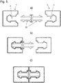
- Figur 1 a und b :
- eine Klick-Verbindung mit zwei Formstücken mit gesondert einsetzbaren, als Widerhaken wirkenden Rückhalte-Elementen, a) vor und b) nach dem Verbinden durch Zusammenklicken;
- Figur 2 a und b:
- eine Klick-Verbindung mit zwei Formstücken mit im Innern der Nuten einstückig angeformten Rückhalte-Elementen mit Hinterschnitt-Flächen, a) vor und b) nach dem Verbinden durch Zusammenklicken;
- Figur 3 a und b :
- eine Klick-Verbindung mit zwei Formstücken mit gesondert einsetzbaren Rückhalte-Elementen mit Hinterschnitt-Flächen, a) vor und b) nach dem Verbinden durch Zusammenklicken;
- Figur 4 a bis d :
- eine Klick-Verbindung mit zwei Formstücken mit gesondert einsetzbaren, innerhalb der Nut hin und her verschiebbaren, als Widerhaken wirkenden Rückhalte-Elementen, a) vor dem Einsetzen der Rückhalte-Elemente, b) nach dem Einsetzen der Rückhalte-Elemente, c) während des Zusammenschiebens und d) nach dem Verbinden durch Zusammenklicken der beiden Formstücke;
- Figur 5 a bis c :
- eine Verbindung mit zwei Formstücken mit losen, als Widerhaken wirkenden Rückhalte-Elementen, a) vor dem Einsetzen der Rückhalte-Elemente, b) nach dem Einsetzen des Rückhalte-Elementes in das eine der beiden Formstücke und c) nach dem Verbinden durch Zusammenklicken der beiden Formstücke;
- Figur 6 a bis c :
- eine Klick-Verbindung mit zwei Formstücken mit losen, federnden Rückhalte-Elementen mit Hinterschnitt-Flächen, a) vor dem Einsetzen der Rückhalte-Elemente, b) nach dem Einsetzen des Rückhalte-Elementes in das eine der beiden Formstücke, und c) nach dem Verbinden durch Zusammenklicken der beiden Formstücke, wonach die Hinterschnitt-Flächen an Rückhalteflächen anschlagen;
- Figur 7 a bis c :
- eine Klick-Verbindung mit zwei Formstücken mit länglichen losen, federnden Rückhalte-Elementen mit Hinterschnitt-Flächen, a) vor dem Einsetzen der Rückhalte-Elemente, b) nach dem Einsetzen des Rückhalte-Elementes in das eine der beiden Formstücke, und c) nach dem Verbinden durch Zusammenklicken der beiden Formstücke, wonach die Hinterschnitt-Flächen an Rückhalteflächen anschlagen;
- Figur 8 a und b :
- eine Klick-Verbindung mit in das Formstück einsetzbaren, als Widerhaken wirkenden Rückhalte-Elementen, wobei das eine Formstück ein Vierfach-Profil ist mit vier Nuten, a) vor dem Zusammenklicken der beiden Formstücke mit den Rückhalte-Elementen in ihrer Nut und b) nach dem Verbinden durch Zusammenklicken der beiden Formstücke;
- Figur 9 a bis c :
- eine Klick-Verbindung mit in die Formstücke einsetzbaren Rückhalte-Elementen mit Hinterschnitt-Flächen, a) vor dem Zusammenklicken und noch vor dem Einsetzen eines der Rückhalte-Elemente, b) während des Zusammenschiebens der beiden Formstücke und c) nach dem vollendeten Verbinden durch Zusammenklicken der beiden Formstücke, wonach die Hinterschnitt-Flächen an Rückhalteflächen anschlagen;
- Figur 10 :
- eine Klick-Verbindung mit in die Formstücke einsetzbaren, als Widerhaken wirkenden Rückhalte-Elementen, wobei in der linken Bildhälfte das linke Formstück mit seinem eingesetzten Rückhalte-Element einem zweiten Formstück in Form eines Mehrfachprofils mit gleichem Rückhalte-Element in einer seiner Nuten gegenüberliegt, und in der rechten Bildhälfte dieses Mehrfachprofil mit einem solchen Formstück zusammengeklickt abgebildet ist;
- Figur 11 a bis c:
- eine Klick-Verbindung mit in die Formstücke schwenkbar einsetzbaren Rückhalte-Elementen mit Hinterschnitt-Flächen, in a) vor dem Zusammenklicken, in b) beim Zusammenschieben und in c) nach fertig erstellter satter und auf Zugkraft belastbarer Verbindung, wonach die Hinterschnitt-Flächen an Rückhalteflächen anschlagen;
- Figur 12 :
- eine Klick-Verbindung mit Hinterschnitt-Flächen als Rückhalte-Elemente und auch Hinterschnitt-Flächen in den Nuten, sodass die Rückhalte-Elemente daran als Widerhaken wirken;
- Figur 13 :
- eine Klick-Verbindung mit Hinterschnitt-Flächen an den Rückhalte-Elementen und auch Hinterschnitt-Flächen in den Nuten, sodass die Rückhalte-Elemente im zusammengeklickten Zustand an diesen Hinterschnitt-Flächen in den Nuten anschlagen, und diese also als Rückhalte-Flächen wirken;
- Figur 14 a und b:
- eine Klick-Verbindung, in
Figur 14 a in offenem Zustand und inFigur 14b mit den als Widerhaken wirkenden Rückhalte-Elementen zusammengeklickt.
- Figure 1 a and b:
- a click connection with two fittings with separately insertable retaining elements acting as barbs, a) before and b) after the connection by clicking together;
- Figure 2 a and b:
- a click connection with two fittings with retaining elements molded in one piece inside the grooves with undercut surfaces, a) before and b) after the connection by clicking together;
- Figure 3 a and b:
- a click connection with two fittings with separately insertable retaining elements with undercut surfaces, a) before and b) after connecting by clicking together;
- Figure 4 a to d:
- a click connection with two fittings with separately insertable, back and forth displaceable within the groove, acting as barbed retaining elements, a) before the insertion of the retaining elements, b) after the insertion of the retaining elements, c) during the Pushing together and d) after connecting by clicking the two fittings together;
- Figure 5 a to c:
- a connection with two fittings with loose, barbed retaining elements, a) before inserting the retaining elements, b) after inserting the retaining element in one of the two fittings and c) after connecting by clicking the two together Fittings;
- Figure 6 a to c:
- a click connection with two fittings with loose, resilient retaining elements with undercut surfaces, a) before inserting the retaining elements, b) after inserting the retaining element into one of the two fittings, and c) after Connect by clicking the two fittings together, after which the undercut surfaces abut against retaining surfaces;
- Figure 7 a to c:
- a click connection with two fittings with elongated, loose, resilient retaining elements with undercut surfaces, a) before inserting the retaining elements, b) after inserting the retaining element into one of the two fittings, and c) after connecting by clicking the two fittings together, after which the undercut surfaces abut against retaining surfaces;
- Figure 8 a and b:
- a click connection with insertable into the fitting, as Barbed-acting retaining elements, one of the shaped pieces being a quadruple profile with four grooves, a) before the two shaped pieces are clicked together with the retaining elements in their groove and b) after connecting by clicking the two shaped pieces together;
- Figure 9 a to c:
- a click connection with retaining elements with undercut surfaces that can be inserted into the fittings, a) before clicking together and before inserting one of the retaining elements, b) during the pushing together of the two fittings and c) after the connection has been completed by clicking together of the two fittings, after which the undercut surfaces abut against retaining surfaces;
- Figure 10:
- a click connection with retaining elements that can be inserted into the fittings and act as barbs, with the left fitting with its retaining element inserted opposite a second fitting in the form of a multiple profile with the same retaining element in one of its grooves in the left half of the picture, and in the right half of the picture this multiple profile is shown clicked together with such a fitting;
- Figure 11 a to c:
- a click connection with retaining elements with undercut surfaces that can be swiveled into the fittings, in a) before clicking together, in b) when pushing together and in c) after a fully established connection that can withstand tensile force, after which the undercut surfaces Attach retaining surfaces;
- Figure 12:
- a click connection with undercut surfaces as retaining elements and also undercut surfaces in the grooves so that the retaining elements act as barbs;
- Figure 13:
- a click connection with undercut surfaces on the retaining elements and also undercut surfaces in the grooves, so that the retaining elements hit these undercut surfaces in the grooves when they are clicked together, and these therefore act as retaining surfaces;
- Figure 14 a and b:
- a click connection, in
Figure 14 a in the open state and inFigure 14b clicked together with the retaining elements acting as barbs.
Das Grundprinzip dieser Klick-Verbindung erschliesst schon aus
Sowohl die Formstücke 1, 2 wie auch die Rückhalte-Elemente 8 mit ihren Hinterschnitt-Flächen sind als flächige Elemente ausgeführt, das heisst die hier sichtbare obere Ebene ist eben, wie auch die Unterseite, mit der diese Elemente flach auf einer ebenen Unterlage aufliegen können. An jedem Rückhalte-Element 8 folgt nach der rauten- oder pfeilförmigen Spitze mit ihren beidseitig anschliessenden Seiten und Kanten 11 ein Schwanzteil 21, das schliesslich in das Ende 7 ausläuft, welches mit seiner zylindrischen Form einen Keder bildet. Beidseits des Schwanzteils 21 des Rückhalte-Elementes 8 formt sein Körper 20 hier je einen elastisch federnden Flügel 12 aus, der nach hinten ausläuft und welcher je einen äusseren Nocken als Widerhaken 6 bildet. Diese beiden Formstücke 1, 2 können nun gegeneinander hin verschoben und zusammengeschoben werden. Dabei schieben die beiden Rückhalte-Elemente 8, weil ja jedes sein Formstück 1, 2 überragt, aneinander vorbei. Die federnden Flügel 12 müssen hierzu leicht elastisch deformiert werden, um am Nocken bzw. Widerhaken 6 des jenseitigen Rückhalte-Elementes 8 vorbei gleiten zu können. Nach Passieren dieser Nocken bzw. Widerhaken 6 klicken bzw. rasten diese Flügel 12 mit ihren hinteren Enden an diesen Widerhaken 6 des dann anliegenden Flügels 12 des anderen Rückhalte-Elementes 8 passgenau ein.Both the
Der Pfeil zwischen den beiden
Solche Formstücke können zum Verbinden X-beliebiger Bauteile eingesetzt werden, wo solche rasch, formschlüssig und auf Zugkraft belastbar miteinander unlösbar miteinander verbunden werden sollen. Die Formstücke 1, 2 können beim Anfertigen der Bauteile direkt aus dem Grundmaterial der Bauteile bestehen oder als Formstücke mit ihren Rückseiten auf die zu verbindenden Teile aufgeleimt, aufgeschweisst oder aufgeschraubt werden. Hierzu können die Bauteile mit viereckigen Nuten versehen sein, in welche die Formstücke 1, 2 formschlüssig und aussen bündig einpassen, sodass ihre Frontseiten 13 hernach also bündig mit den Vorderseiten der Bauteile verlaufen. Das Innere der Nuten 3 bzw. die Böden 10 der Nuten 3 bieten die Möglichkeit, mittels Bohrungen Löcher in den Boden 10 einzubringen, sodass die Formstücke 1, 2 mit ihren Nutenböden auf Bauteile aufgesetzt und mittels Schrauben mit denselben verschraubt werden können.Such fittings can be used to connect any number of components where such components are to be connected to one another in a non-detachable manner quickly, positively and with tensile force. The molded
Die
Die
Die Ausführung nach
Die
Die
Die
Die
Die
Wenn die Rückhalte-Elemente 8 an beiden Formstücken 1, 2 eingesetzt sind, so überragen diese Rückhalte-Elemente 8 die Formstücke 1, 2 auf der offenen Seite der Nut 3. Werden sie nun mit ihren Stirnflächen 13 voran einander angenähert, so stellt sich das wie in
In
Die
Die
Die
Die
Für die künstlerische Gestaltung von Boden- und Wandelementen können zum Beispiel die Parkettplatten oder andere ähnliche Platten nach Belieben geschnitten werden und in die Schnittflächen kann mit einer Oberflächenfräse selber das Rahmenprofil bzw. die nötige Nut gefräst werden, sodass in diese auch wieder Doppel-Rückhalte-Elemente eingesetzt werden können. Dies ermöglicht unzählige Varianten beim Verlegen und Montieren von Elementen auf Böden, Decken, Wänden usw. Einer Mosaikgestaltung sind so keine Grenzen gesetzt. Der Typ der Klickverbindung mit der mittigen Auflageplatte 26 nach
Bei allen Ausführungen kann in der Stirnfläche, das heisst in der Verbindungsfläche 13 der Formstücke eine Nut vorgesehen werden, um eine Gummi-Dichtung aufzunehmen, die dann zwischen den zusammengeklickten Formstücken die Stirnflächen 13 abdichtet. Das ist vor allem für mit solchen Klick-Verbindungen auf Stoss zusammengebaute Innen- und Aussenwände von Immobilien vorteilhaft, damit im Schlitz der Verbindung kein Luftzug entstehen kann.In all designs, a groove can be provided in the end face, that is to say in the connecting
- 1,21.2
- FormstückeFittings
- 3,43.4
- NutGroove
- 4,54.5
-
Flankenseiten der Nut 3Flank sides of the
groove 3 - 66th
- Widerhaken, RückhalteflächeBarb, retaining surface
- 77th
-
zylindrisches Ende der Rückhalteelemente 8cylindrical end of the retaining
elements 8 - 88th
- schwenkbar einsetzbares Rückhalte-Elementpivotable retaining element
- 99
- elastisch schwenkbares Rückhalte-Element am Nutbodenelastically pivotable retaining element on the bottom of the groove
- 1010
- NutbodenGroove bottom
- 1111
- im Bereich der Spitze beidseits Widerhaken oder Rückhalte-Flächen wirkende Hinterschnitt-Flächen 11In the area of the tip, undercut surfaces 11 acting on both sides with barbs or retaining surfaces
- 1212th
- beidseits federnde Flügel an den Rückhalte-Elementenresilient wings on both sides of the retaining elements
- 1313th
- Stirnfläche/Frontseite/Verbindungsfläche des FormstückesFront face / front face / connecting surface of the fitting
- 1414th
-
Aufnahmenut für Rückhalte-Element 8Groove for retaining
element 8 - 1515th
- Formstück als MehrfachprofilForm piece as a multiple profile
- 1616
- Bogennut für Aufnahme des Rückhalte-ElementesCurved groove for holding the retaining element
- 1717th
- Bogenschwanz des Rückhalte-ElementesArched tail of the retaining element
- 1818th
-
Rückhaltefläche auf Innenseite der Nuten 3Retention surface on the inside of the
grooves 3 - 1919th
-
Zentrale Öffnung in bogenförmiger Ausnehmung 16Central opening in
arcuate recess 16 - 2020th
- Körper des Rückhalte-ElementesBody of the retaining element
- 2121
- Schwanzteil des Rückhalte-ElementesTail part of the retaining element
- 2222nd
- elastische biegsame Gabelzinkenelastic, flexible fork tines
- 2323
-
Aussenkante an Flügel 12 (
Figur 9 )Outer edge of leaf 12 (Figure 9 ) - 2424
- Nase am Rückhalte-ElementNose on the retaining element
- 2525th
-
seitliche elastisch biegsame Flügel an der Nase 24lateral, resiliently flexible wings on the
nose 24 - 2626th
- Auflageplatte als Stossfänger und Distanzhalter für FugenSupport plate as a bumper and spacer for joints
- 2727
- Flügel für lösbare VerbindungWing for detachable connection
- 2828
-
Schrägflächen an Flügel 27Sloping surfaces on
wing 27 - 2929
-
Schrägflächen für 28 im Innern der Nut 3Inclined surfaces for 28 inside the
groove 3
Claims (11)
Applications Claiming Priority (1)
| Application Number | Priority Date | Filing Date | Title |
|---|---|---|---|
| CH00309/20A CH717236A2 (en) | 2020-03-17 | 2020-03-17 | Click connection. |
Publications (3)
| Publication Number | Publication Date |
|---|---|
| EP3882473A1 true EP3882473A1 (en) | 2021-09-22 |
| EP3882473B1 EP3882473B1 (en) | 2023-11-15 |
| EP3882473C0 EP3882473C0 (en) | 2023-11-15 |
Family
ID=75202938
Family Applications (1)
| Application Number | Title | Priority Date | Filing Date |
|---|---|---|---|
| EP21162759.1A Active EP3882473B1 (en) | 2020-03-17 | 2021-03-16 | Click-connection |
Country Status (2)
| Country | Link |
|---|---|
| EP (1) | EP3882473B1 (en) |
| CH (1) | CH717236A2 (en) |
Cited By (1)
| Publication number | Priority date | Publication date | Assignee | Title |
|---|---|---|---|---|
| WO2024082900A1 (en) * | 2022-10-20 | 2024-04-25 | 杭州海康机器人股份有限公司 | Mounting structure of housing, and intelligent mobile robot having mounting structure |
Citations (5)
| Publication number | Priority date | Publication date | Assignee | Title |
|---|---|---|---|---|
| US6036398A (en) * | 1998-06-22 | 2000-03-14 | Theodorou; Antonis | Extruded frame member for structural connection and method of forming same |
| US20130287484A1 (en) * | 2011-01-14 | 2013-10-31 | Sean Phillips | Connector assembly for an article of furniture |
| JP2016056859A (en) * | 2014-09-08 | 2016-04-21 | 川上産業株式会社 | Connection structure between plastic hollow plate and structure member and partition |
| ES1220438U (en) * | 2018-10-02 | 2018-11-15 | Unex Aparellaje Electrico S.L. | Cable ladder (Machine-translation by Google Translate, not legally binding) |
| WO2019137824A1 (en) * | 2018-01-15 | 2019-07-18 | Josef Stengel | Method for producing a wall lining or floor covering |
-
2020
- 2020-03-17 CH CH00309/20A patent/CH717236A2/en not_active Application Discontinuation
-
2021
- 2021-03-16 EP EP21162759.1A patent/EP3882473B1/en active Active
Patent Citations (5)
| Publication number | Priority date | Publication date | Assignee | Title |
|---|---|---|---|---|
| US6036398A (en) * | 1998-06-22 | 2000-03-14 | Theodorou; Antonis | Extruded frame member for structural connection and method of forming same |
| US20130287484A1 (en) * | 2011-01-14 | 2013-10-31 | Sean Phillips | Connector assembly for an article of furniture |
| JP2016056859A (en) * | 2014-09-08 | 2016-04-21 | 川上産業株式会社 | Connection structure between plastic hollow plate and structure member and partition |
| WO2019137824A1 (en) * | 2018-01-15 | 2019-07-18 | Josef Stengel | Method for producing a wall lining or floor covering |
| ES1220438U (en) * | 2018-10-02 | 2018-11-15 | Unex Aparellaje Electrico S.L. | Cable ladder (Machine-translation by Google Translate, not legally binding) |
Cited By (1)
| Publication number | Priority date | Publication date | Assignee | Title |
|---|---|---|---|---|
| WO2024082900A1 (en) * | 2022-10-20 | 2024-04-25 | 杭州海康机器人股份有限公司 | Mounting structure of housing, and intelligent mobile robot having mounting structure |
Also Published As
| Publication number | Publication date |
|---|---|
| EP3882473B1 (en) | 2023-11-15 |
| EP3882473C0 (en) | 2023-11-15 |
| CH717236A2 (en) | 2021-09-30 |
Similar Documents
| Publication | Publication Date | Title |
|---|---|---|
| EP1423315B1 (en) | Chain-transport system with add-on components | |
| DE2941008B1 (en) | frame | |
| DE202006021264U1 (en) | Door and window frame with an undercut engagement area for a gear unit | |
| DE3912135C3 (en) | Wood / metal windows | |
| DE102008026498A1 (en) | Fixing of solar modules on building structures | |
| EP3421691B1 (en) | Modular locking cylinder | |
| EP3882473A1 (en) | Click-connection | |
| DE202008013046U1 (en) | Connectors | |
| DE3729215C1 (en) | Faceplate corner connection | |
| DE3437430C1 (en) | Joint connection of a transom profile with a frame or bar profile for heat-insulated windows, doors or the like | |
| EP0674084B1 (en) | Frame for a window pane | |
| DE102014207322A1 (en) | Butt joint arrangement, window / door frame or window / door frame and frame profile element | |
| EP2995747B1 (en) | Mechanical connection for panels and method of mounting a locking tongue in a panel | |
| DE102013000624A1 (en) | Nut for fastening components to a profiled element via screw means and method for their assembly | |
| DE102006059750B4 (en) | Furniture linking element and furniture equipped therewith | |
| DE102012111208A1 (en) | expansion anchor | |
| DE202008012005U1 (en) | Worktop connectors | |
| EP3067495B1 (en) | Holder element of a fitting part of an espagnolette fitting | |
| DE2320515A1 (en) | CONSTRUCTION ELEMENT FOR ASSEMBLING PIPES | |
| EP3263788A1 (en) | Connection of two timber beams | |
| EP2251521A2 (en) | Profile connector, frame and insect protective grid | |
| DE102008007135A1 (en) | fastener | |
| EP0805281A1 (en) | Fastening device for two rod-shaped profile members | |
| EP2543803B1 (en) | Drive rod for a fitting on a connecting rod | |
| DE10043443B4 (en) | Window or door frame with a connector |
Legal Events
| Date | Code | Title | Description |
|---|---|---|---|
| PUAI | Public reference made under article 153(3) epc to a published international application that has entered the european phase |
Free format text: ORIGINAL CODE: 0009012 |
|
| STAA | Information on the status of an ep patent application or granted ep patent |
Free format text: STATUS: THE APPLICATION HAS BEEN PUBLISHED |
|
| AK | Designated contracting states |
Kind code of ref document: A1 Designated state(s): AL AT BE BG CH CY CZ DE DK EE ES FI FR GB GR HR HU IE IS IT LI LT LU LV MC MK MT NL NO PL PT RO RS SE SI SK SM TR |
|
| STAA | Information on the status of an ep patent application or granted ep patent |
Free format text: STATUS: REQUEST FOR EXAMINATION WAS MADE |
|
| 17P | Request for examination filed |
Effective date: 20220310 |
|
| RBV | Designated contracting states (corrected) |
Designated state(s): AL AT BE BG CH CY CZ DE DK EE ES FI FR GB GR HR HU IE IS IT LI LT LU LV MC MK MT NL NO PL PT RO RS SE SI SK SM TR |
|
| GRAP | Despatch of communication of intention to grant a patent |
Free format text: ORIGINAL CODE: EPIDOSNIGR1 |
|
| STAA | Information on the status of an ep patent application or granted ep patent |
Free format text: STATUS: GRANT OF PATENT IS INTENDED |
|
| INTG | Intention to grant announced |
Effective date: 20230609 |
|
| GRAS | Grant fee paid |
Free format text: ORIGINAL CODE: EPIDOSNIGR3 |
|
| GRAA | (expected) grant |
Free format text: ORIGINAL CODE: 0009210 |
|
| STAA | Information on the status of an ep patent application or granted ep patent |
Free format text: STATUS: THE PATENT HAS BEEN GRANTED |
|
| AK | Designated contracting states |
Kind code of ref document: B1 Designated state(s): AL AT BE BG CH CY CZ DE DK EE ES FI FR GB GR HR HU IE IS IT LI LT LU LV MC MK MT NL NO PL PT RO RS SE SI SK SM TR |
|
| REG | Reference to a national code |
Ref country code: CH Ref legal event code: EP Ref country code: GB Ref legal event code: FG4D Free format text: NOT ENGLISH |
|
| REG | Reference to a national code |
Ref country code: DE Ref legal event code: R096 Ref document number: 502021001942 Country of ref document: DE |
|
| REG | Reference to a national code |
Ref country code: IE Ref legal event code: FG4D Free format text: LANGUAGE OF EP DOCUMENT: GERMAN |
|
| U01 | Request for unitary effect filed |
Effective date: 20231211 |
|
| U07 | Unitary effect registered |
Designated state(s): AT BE BG DE DK EE FI FR IT LT LU LV MT NL PT SE SI Effective date: 20231215 |
|
| U20 | Renewal fee paid [unitary effect] |
Year of fee payment: 4 Effective date: 20240205 |
|
| PG25 | Lapsed in a contracting state [announced via postgrant information from national office to epo] |
Ref country code: GR Free format text: LAPSE BECAUSE OF FAILURE TO SUBMIT A TRANSLATION OF THE DESCRIPTION OR TO PAY THE FEE WITHIN THE PRESCRIBED TIME-LIMIT Effective date: 20240216 |
|
| PG25 | Lapsed in a contracting state [announced via postgrant information from national office to epo] |
Ref country code: IS Free format text: LAPSE BECAUSE OF FAILURE TO SUBMIT A TRANSLATION OF THE DESCRIPTION OR TO PAY THE FEE WITHIN THE PRESCRIBED TIME-LIMIT Effective date: 20240315 |
|
| PG25 | Lapsed in a contracting state [announced via postgrant information from national office to epo] |
Ref country code: ES Free format text: LAPSE BECAUSE OF FAILURE TO SUBMIT A TRANSLATION OF THE DESCRIPTION OR TO PAY THE FEE WITHIN THE PRESCRIBED TIME-LIMIT Effective date: 20231115 |
|
| PG25 | Lapsed in a contracting state [announced via postgrant information from national office to epo] |
Ref country code: IS Free format text: LAPSE BECAUSE OF FAILURE TO SUBMIT A TRANSLATION OF THE DESCRIPTION OR TO PAY THE FEE WITHIN THE PRESCRIBED TIME-LIMIT Effective date: 20240315 Ref country code: GR Free format text: LAPSE BECAUSE OF FAILURE TO SUBMIT A TRANSLATION OF THE DESCRIPTION OR TO PAY THE FEE WITHIN THE PRESCRIBED TIME-LIMIT Effective date: 20240216 Ref country code: ES Free format text: LAPSE BECAUSE OF FAILURE TO SUBMIT A TRANSLATION OF THE DESCRIPTION OR TO PAY THE FEE WITHIN THE PRESCRIBED TIME-LIMIT Effective date: 20231115 |