EP3881663A1 - Mower blade device - Google Patents
Mower blade device Download PDFInfo
- Publication number
- EP3881663A1 EP3881663A1 EP20204706.4A EP20204706A EP3881663A1 EP 3881663 A1 EP3881663 A1 EP 3881663A1 EP 20204706 A EP20204706 A EP 20204706A EP 3881663 A1 EP3881663 A1 EP 3881663A1
- Authority
- EP
- European Patent Office
- Prior art keywords
- knife
- mowing
- cutting knife
- cutting
- designed
- Prior art date
- Legal status (The legal status is an assumption and is not a legal conclusion. Google has not performed a legal analysis and makes no representation as to the accuracy of the status listed.)
- Granted
Links
Images
Classifications
-
- A—HUMAN NECESSITIES
- A01—AGRICULTURE; FORESTRY; ANIMAL HUSBANDRY; HUNTING; TRAPPING; FISHING
- A01D—HARVESTING; MOWING
- A01D34/00—Mowers; Mowing apparatus of harvesters
- A01D34/01—Mowers; Mowing apparatus of harvesters characterised by features relating to the type of cutting apparatus
- A01D34/02—Mowers; Mowing apparatus of harvesters characterised by features relating to the type of cutting apparatus having reciprocating cutters
- A01D34/13—Cutting apparatus
- A01D34/14—Knife-bars
- A01D34/145—Devices for connecting the knife-bars to the driving mechanism
-
- A—HUMAN NECESSITIES
- A01—AGRICULTURE; FORESTRY; ANIMAL HUSBANDRY; HUNTING; TRAPPING; FISHING
- A01D—HARVESTING; MOWING
- A01D34/00—Mowers; Mowing apparatus of harvesters
- A01D34/01—Mowers; Mowing apparatus of harvesters characterised by features relating to the type of cutting apparatus
- A01D34/02—Mowers; Mowing apparatus of harvesters characterised by features relating to the type of cutting apparatus having reciprocating cutters
- A01D34/13—Cutting apparatus
- A01D34/135—Cutting apparatus having oppositely movable cooperating knife-bars
Definitions
- the invention relates to a mowing knife device with a double knife cutting system, the double knife cutting system comprising an upper cutting knife and a lower cutting knife, which are designed to be movable relative to one another by means of a one-sided drive.
- the pamphlet DE19541898A1 relates to a mulching mower, the reciprocating upper knife and the standing lower knife are equipped with approximately triangular cutting areas, the upper knife being mounted by means of knife holders arranged above it, and the upper and lower knives are integrally formed and the upper knife in the area under the knife holders Has elongated holes running in the longitudinal direction of the cutting mechanism, into which the guide strips of the knife holders protrude.
- the pamphlet DE2626073A1 relates to a cutter bar with a guide for one or more driven, reciprocating knives.
- Such cutter bars are usually attached to the side of the tractor. However, they are also used for rear mowers on the tractor or for front mowers on the combine harvester.
- the individual knife blades are firmly riveted to a knife stick.
- the knife bar is guided through corresponding recesses in the so-called fingers, which are firmly arranged on the cutter bar. The edges of the fingers serve as counter blades for the knife blades resting on the fingers.
- a knife holder arranged on the top of the cutter bar prevents the knife blades from deviating up.
- the knife blades together with the knife stick form a knife unit which is connected at one of its free ends to a drive rod of the crank mechanism.
- the disadvantage of this known mowing knife device is that the drive forces act directly on the knife, which is constantly alternating with pressure and tension. The consequence of this is that the knife blades and the knife stick must be dimensioned relatively strong, which conversely increases the mass of the cutting knife. In the event of overload, therefore, breaks often occur at the connection point between the drive rod and the knife. A larger dimensioning of the knife parts is not economically justifiable, since they are wearing parts with a relatively short service life.
- Another disadvantage is that both changing the cutting knife and renewing the knife blades is time-consuming and costly.
- the object of the invention is to create a particularly efficient concept of a mowing knife device belonging to the technical field mentioned at the beginning, which enables simple handling and an increased service life.
- the invention relates to a mowing knife device with a double knife cutting system, the double knife cutting system comprising an upper cutting knife and a lower cutting knife which are designed to be movable relative to one another by means of a one-sided drive, at least the upper cutting knife or the lower cutting knife each comprising several blade elements, which are formed connected to one another via a knife back, and wherein the blade elements and the knife back are designed as a common integral component, and wherein the mowing knife device is one has exchangeable cutter head for initiating a drive movement of a lateral drive on the double-knife cutting system.
- the cutter head has an engagement element which is designed to engage in a corresponding engagement receptacle in the knife back of the upper cutting knife or the lower cutting knife.
- the engagement element comprises at least two engagement projections. This has the advantage, on the one hand, that a very simple but fixed association between cutter head and cutting knife can be realized. Additional engagement projections are conceivable, but not absolutely necessary for the function. Therefore, the implementation by means of two engagement elements is particularly efficient and easy to manufacture.
- the engagement receptacle of the knife back includes engagement openings corresponding to the engagement elements.
- This has the particular advantage that no additional components have to be arranged between the knife back and the knife head.
- the engagement openings can be punched directly into the back of the knife.
- the cutting knives including the blade elements and the knife back as a one-piece blade made of flat steel. This flat steel enables both the punching out of the blade elements and the punching out of the engagement openings. Overall, this makes the manufacture of the mowing device and its assembly particularly efficient.
- the knife head has an elastic section which is formed between a connecting section of the knife head with the knife back and a connection to the drive.
- a stiff, inflexible cutter head as the connection between the cutting knife and the drive connected to the side loads all components of the functional chain, at least mechanically. This also increases the wear and tear on the entire mower blade device and shortens its service life clear.
- the elastic section of the cutter head can in particular dampen vibrations and deformations, thereby relieving the load on the mowing knife device. Thus, the elastic section increases the service life.
- the elastic section is made from a metal.
- Metal has a suitable strength and at the same time can have the necessary elasticity.
- the elastic section is made from a spring steel.
- the elastic section for damping a movement is formed in a plane which is formed parallel to the plane defined by the blade elements of the upper cutting knife or the lower cutting knife.
- the upper cutting knife is designed to be connected to a knife bar by means of an upper holding device, the upper holding device being mounted on the knife bar by means of a guide bushing.
- a pretensioned tension spring for exerting a pressing force of the upper cutting knife on the lower cutting knife is arranged inside the guide bushing.
- the cutting knives are often severely deformed by impurities, such as stones, between the upper cutting knife and the lower cutting knife. These deformations put additional stress on the cutting blades and increase wear. Due to the spring mounted in the guide bushing, the holding device can translationally yield in the opposite direction to the pressing force, whereby the impurities are removed automatically and permanent wear and tear on the cutting blades can be reduced. This extends the service life of the mower blade device, since wear is additionally reduced.
- the spring is suitable for reducing mechanical influences, such as impacts or vibrations, which act on the cutting knife during operation and are oriented orthogonally to that plane which is defined by the blade elements of the upper cutting knife or the lower cutting knife.
- the mowing knife device comprises damping elements which are designed to dampen loads in different directions and thus to reduce wear.
- the elastic section of the cutter head is designed to dampen mechanical loads which occur in a plane which is arranged parallel to that plane which is defined by the blade elements of the upper cutting knife or the lower cutting knife. These mechanical influences arise, for example, from blows or vibrations which act on the cutting knife from a front side during operation.
- the tension spring within the guide bushing enables mechanical influences which act on the cutting knife during operation and are oriented orthogonally to the plane defined by the blade elements of the upper cutting knife or the lower cutting knife to be absorbed or dampened.
- the mowing knife device thus comprises an overall very low-wear solution with a long service life.
- the guide bushing is held in a threaded bushing.
- the threaded bushing can be arranged so that it is protected against contamination and a suitable introduction of force can take place from the holding device via the guide bushing onto the threaded bushing.
- the threaded bushing is designed to be screwable to the cutter bar via an external thread. This gives the added benefit achieves that the threaded bush ensures a reliable introduction of force into the cutter bar. It is also possible to dismantle or change the threaded bushing without increased installation effort.
- the absolute position of the threaded bushing relative to the cutter bar can be changed by means of the thread. This can be advantageous, for example, after a cutting knife change for precise setting of the mowing knife device.
- the tension spring is designed such that it can be tensioned by means of a spring screw.
- the technical advantage is achieved that the tension and thus the tensile force of the spring is adjustable.
- the tension can be increased or reduced as required by actuating the spring screw. For example, this can be advantageous after changing the mowing knife in order to ensure the optimal setting of the mowing knife device. It is also possible to vary the tension of the tension spring and thus the contact pressure of the upper cutting knife on the lower cutting knife for a specific application.
- the spring screw is designed to be adjustable from the outside via a socket cover.
- the socket cover is particularly easy to operate.
- a special tool is not absolutely necessary.
- the socket cover can be operated manually or by means of a simple, commercially available tool.
- a screwdriver, an Allen key, a combination wrench or open-end wrench are suitable for this purpose.
- the upper cutting knife including the blade elements and the knife back is designed as a one-piece blade, in particular made from flat steel.
- the formation from a flat steel is particularly inexpensive to manufacture.
- the design from flat steel is associated with weight savings, which in turn reduce wear and thus have a positive effect on the service life of the mower blade device.
- the lower cutting knife can also be included the blade elements and the knife back be designed as a one-piece blade, in particular made of a flat steel.
- a particular advantage results from the reduction in the thickness of the upper cutting knife and the lower cutting knife, which are connected to the one-piece design of the blade.
- the reduced thickness of the cutting knives improves the sliding of cut material during operation of the mowing knife device, since all edges are eliminated by thickening of the material on the back of the knife, such as those caused by riveted or welded blade elements.
- each blade element comprises two V-shaped cutting edges, the cutting edge of a first blade element and the opposite cutting edge of an adjacent blade element extending continuously over the back of the knife.
- the cutting edges are continuous and there are no longer any dead edges. This increases the efficiency of the mower knife device considerably.
- this embodiment is advantageous in connection with that design according to which the blade elements and the knife back are designed as a single-piece blade, in particular made of flat steel. Due to the particularly flat design of the one-piece blade, the continuously formed cutting edges can be completely ground and sharpened particularly easily.
- a plurality of cutting knives is arranged in series along the knife bar, with a lower cutting knife usually being assigned to each upper cutting knife.
- a plurality of upper cutting knives and lower cutting knives are arranged along the knife bar, an upper holding device being assigned to each third upper cutting knife.
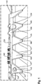
- the Figure 1 shows an upper cutting knife 140 with cutter head 200.
- the upper cutting knife 140 is part of the mowing knife device (not shown), which comprises a double-knife cutting system (not shown) with the upper cutting knife 140 and a lower cutting knife (not shown).
- the upper cutting knife 140 and the lower cutting knife 180 are moved relative to one another by means of a drive 114.
- Both the upper cutting knife 140 and the lower cutting knife 180 each have a plurality of blade elements 145 which are connected to one another via a knife back 144, 184.
- the blade elements 145 and the knife back 144, 184 are thus formed as a common integral component. For example they are punched out of a flat steel, whereby the production is very inexpensive.
- the mowing knife device 100 comprises an exchangeable knife head 200 in order to transmit a drive movement from a lateral drive (not shown) to the double knife cutting system 111.
- the cutter head 200 has an elastic section 220 which is formed between a connection section 240 of the cutter head 200 with the upper cutting knife 140 and a connection 230 for connection to a drive.
- the entire cutter head 200 with connecting section 240, elastic section 200 and connection 230 is made from one piece.
- the cutter head can also be made from flat steel, as a result of which the elastic section 220 is also made from metal.
- the elastic section 220 can in particular realize a damping function in a plane which is formed parallel to the plane defined by the blade elements 145 of the upper cutting knife 140.
- the connecting section 240 is fixed to the upper cutting knife 140 by means of screws and rivets.
- the connecting section 240 of the cutter head 200 comprises an engaging element (not shown) which is provided for engaging in a corresponding engaging receptacle (not shown) in the knife back 144 of the upper cutting knife (140).
- both the upper cutting knife 140 and the lower cutting knife 180 each comprise a plurality of blade elements 145 which are connected to one another via the knife back 144, 184 and are designed as a common integral component.
- each blade element 145 has two V-shaped cutting edges 147.
- the cutting edge 147 is interrupted by a flattened cutting knife tip 146.
- the cutting edge 147 of a first blade element 145 and the opposite cutting edge 147 of an adjacent blade element 145 extend continuously over the knife back 144, 184, whereby the cutting edge 147 is formed continuously over the knife back 144.
- a cutting knife bearing 142 in the form of a pin is located on an upper side of a blade element 145.
- the cutting knife bearing 142 is used to connect the upper cutting knife 140 to an upper holding device 150.
- the function of the upper holding device 150 is shown in FIG Figure 3 explained in detail.
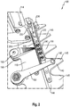
- the Figure 2 shows a double knife cutting system 111 with drive 114 and upper holding device 150.
- the cutting knife device 100 comprises a knife bar 110 which carries a double knife cutting system 111.
- the double knife cutting system 111 includes the upper cutting knife 140 and the lower cutting knife 180 (not shown).
- the upper cutting knife 140 and the lower cutting knife 180 are moved relative to one another by means of a drive 114, for example a crankshaft drive designed on one side.
- the upper cutting knife 140 is connected to the knife bar 110 by means of an upper holding device 150.
- the upper holding device 150 is mounted on the cutter bar 110.
- a guide bushing (not shown) allows the necessary mobility of the upper holding device 150 with respect to the cutter bar 110, which occurs during the operation of the mowing knife device 100 due to the relative movement of the double knife cutting system 111.
- a lower holding device 190 with an easily accessible screw head 193 which is connected to a screw 192 (not shown).
- the screw 192 is used to fix the lower holding device 190 to the cutter bar 110.
- the lower holding device 190 connects the lower cutting knife 180 to the cutter bar 110.
- Both the upper cutting knife 140 and the lower cutting knife 180 are each connected to the drive 114 via an exchangeable cutter head 200.
- Each of the two cutter heads 200 i.e. the cutter head 200 of the upper cutting knife 140 and the cutter head 200 of the lower cutting knife 180, has an elastic section 220 which is between a connecting section 240 of the cutter head 200 with the cutting knife 140, 180 and a connection 230 for connection to the drive 114 is arranged.
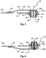
- the Figure 3 shows a mowing knife device 100 according to the invention in a sectional view at the level of the upper holding device 150 according to an exemplary embodiment.
- the mowing knife device 100 comprises the knife bar 110 and the double knife cutting system 111, the double knife cutting system 111 comprising the upper cutting knife 140 and the lower cutting knife 180 (not shown).
- the upper cutting knife 140 is connected to the knife bar 110 by means of the upper holding device 150.
- the upper holding device 150 is supported on the cutter bar 110 via a guide bush 160A.
- the guide bushing itself is arranged in a threaded bushing 164A, which in turn can be screwed to the cutter bar 110 via an external thread 162.
- To screw the threaded bushing 160A it is passed through the receptacle 112 in the cutter bar 110.
- the screw connection of the threaded bushing 164A is additionally secured by a lock nut 163. Inside the threaded bushing 164A there is a bearing 166 which supports the guide bushing 160A with almost little friction for both a rotary and a translational movement with respect to the threaded bushing 164A.
- the bearing 166 is formed on both the upper side and the lower side of the threaded bushing 164A, as a result of which various bearing functions can be implemented.
- the rotary bearing component which is generated due to the movement of the upper and lower cutting blades 140, 180 relative to one another, can be accommodated, for example, through the use of an annular roller bearing.
- the translational movement component stresses the guide bush 160A in the longitudinal direction, which is why the arrangement of a slide bearing is advantageous.
- a bearing that can absorb both the rotational load and the load in the longitudinal direction of the guide bush is ideal.
- the storage additionally reduces the wear and tear on the mower blade device 100 and thus increases the service life of the mower blade device as a whole.
- a pretensioned tension spring 170 is located inside the guide bushing 160A.
- the tension spring 170 is connected at the first end to the upper holding device 150 via a spring screw 172.
- the tension spring 170 extends through the guide bushing 160A and is at its second end with a bushing cover 174 connected.
- the socket cover 174 has a radial protrusion 168 with respect to the threaded bush 164A, whereby the tension spring 170 can on the one hand be placed under tensile stress and on the other hand can be adjusted from the outside via the socket cover 174.
- the tensile stress of the tension spring 170 pulls the upper holding device 150 onto the cutter bar 110. Tightening the upper holding device 150 to the cutter bar 110 causes a pressing force of the upper cutting knife 140 on the lower cutting knife 180 (not shown).
- the guide bushing 160A ensures via its bearings 166 within the threaded bushing 164A that the tension spring 170 can only be subjected to tension. As a result, the pressing force of the upper cutting knife 140 on the lower cutting knife 180 is not generated by a tilting movement of the upper holding device 150, but rather is transmitted by a pure pulling movement of the upper holding device 150.
- the effective direction of the pressing force on the upper cutting knife 140 thus acts parallel to the longitudinal direction of the guide bush 160A.
- the upper holding device 150 also has a crank 152.
- the crank 152 is arranged between the guide bush 160A and the upper cutting knife 140, as a result of which the contact pressure of the tension spring 170 can be optimally transmitted from the upper cutting knife 140 to the lower cutting knife 180.
- the offset 152 thus compensates for the spatial expansion of the tension spring 170, which is arranged orthogonally to the cutter bar due to the orientation of the guide bushing 160A.
- the upper cutting knife 140 is guided in the cutting knife bearing 142 of the upper holding device 150.
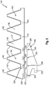
- the Figure 4 shows a mowing knife device 100 according to the invention in a sectional view at the level of the lower holding device 190 according to an exemplary embodiment.
- the lower holding device 190 is firmly connected to the cutter bar 110 without a spring element. The purpose of this is, in particular, that the already described contact force of the upper cutting knife 140 generated by the tension spring 170 on the lower cutting knife 180 can be absorbed.
- the lower holding device 190 is fixed to the cutter bar 110 by means of a guide bush 160B.
- the guide bushing 160B lies within a threaded bushing 164B, which is screwed to the cutter bar 110 via an external thread 162.
- An additional lock nut 163 additionally secures the screwed-in threaded bushing 164B on the cutter bar 110.
- the threaded bushing 164B can thus be dismantled or changed without increased assembly effort.
- the absolute position of the threaded bush 164B relative to the cutter bar 110 can be changed by means of the thread of the threaded bushing 164B. This enables a precise adjustment of the lower holding device 190 in coordination with the upper holding device 150.
- the lower holding device 190 has a screw 192 which extends completely through the guide bushing 164B and fixes the lower holding device 190 to the cutter bar 110.
- the screw 192 has an easily accessible screw head 193 by means of which the lower holding device 190 with the cutter bar 110 can be easily fixed or released.
- a symmetrical introduction of force is achieved.
- the lower holding device 190 has a crank 194.
- the crank 194 is arranged between the guide bush 160B and the lower cutting knife 180.
- the lower cutting knife 180 is guided in a cutting knife bearing 142 of the lower holding device 190.
- the Figure 5 shows a schematic representation of an upper cutting knife 140 with knife head 200.
- the upper cutting knife 140 comprises a plurality of blade elements 145, which are formed connected to one another via the knife back 144.
- the blade elements 145 and the knife back 144 thus form a common integral component which is produced, for example, stamped out of flat steel.
- the replaceable cutter head 200 is shown, which transmits the drive movement of a lateral drive (not shown) to the upper cutting knife 140.
- the cutter head 200 has an engaging element 202 which is for engaging in a corresponding engagement receptacle 206 is formed in the knife back 200 of the upper cutting knife 140.
- the engagement element 202 of the cutter head 200 comprises a total of four engagement projections 204 which correspond to a total of four engagement openings 208 which are made in the knife back 200 of the upper cutting knife.
- Each blade element 145 has two V-shaped cutting edges 147.
- the cutting edges 147 are interrupted at each cutting knife tip 146, while the cutting edges 147 of two adjacent blade elements 145 extend continuously over the knife back 144.
- Every third blade element 145 of the upper cutting knife 140 has a cutting knife bearing 142 which is designed for the arrangement of the upper holding device 150.
- Both the upper cutting knife 140, the knife head 200 and the lower cutting knife 180 can be made from flat steel, with all openings and contours being able to be punched out.
Landscapes
- Life Sciences & Earth Sciences (AREA)
- Environmental Sciences (AREA)
- Harvester Elements (AREA)
Abstract
Die Erfindung betrifft eine Mähmesservorrichtung (100) mit einem Doppelmesser-Schneidsystem (111), wobei das Doppelmesser-Schneidsystem (111) ein oberes Schneidmesser (140) und ein unteres Schneidmesser (180) umfasst, welche mittels eines einseitigen Antriebs (114) relativ zueinander bewegbar ausgebildet sind, wobei zumindest das obere Schneidmesser (140) oder das untere Schneidmesser (180) jeweils mehrere Klingenelemente (145) umfasst, die über einen Messerrücken (144, 184) miteinander verbunden ausgebildet sind, und wobei die Klingenelemente (145) und der Messerrücken (144, 184) als gemeinsames integrales Bauteil ausgebildet sind, und wobei die Mähmesservorrichtung (100) einen auswechselbaren Messerkopf (200) zum Einleiten einer Antriebsbewegung eines seitlichen Antriebs (144) auf das Doppelmesser-Schneidsystem (111) aufweist.The invention relates to a mowing knife device (100) with a double knife cutting system (111), the double knife cutting system (111) comprising an upper cutting knife (140) and a lower cutting knife (180), which by means of a one-sided drive (114) relative to one another are movable, wherein at least the upper cutting knife (140) or the lower cutting knife (180) each comprises a plurality of blade elements (145) which are connected to one another via a knife back (144, 184), and wherein the blade elements (145) and the Knife backs (144, 184) are designed as a common integral component, and wherein the mowing knife device (100) has an exchangeable knife head (200) for initiating a drive movement of a lateral drive (144) on the double knife cutting system (111).
Description
Die Erfindung betrifft eine Mähmesservorrichtung mit einem Doppelmesser-Schneidsystem, wobei das Doppelmesser-Schneidsystem ein oberes Schneidmesser und ein unteres Schneidmesser umfasst, welche mittels eines einseitigen Antriebs relativ zueinander bewegbar ausgebildet sind.The invention relates to a mowing knife device with a double knife cutting system, the double knife cutting system comprising an upper cutting knife and a lower cutting knife, which are designed to be movable relative to one another by means of a one-sided drive.
Die Druckschrift
Die Druckschrift
Ein weiterer Nachteil ist, dass sowohl das Auswechseln des Schneidmessers als auch das Erneuern der Messerklingen zeitraubend und kostenaufwendig ist.Another disadvantage is that both changing the cutting knife and renewing the knife blades is time-consuming and costly.
Ein zusätzlicher Nachteil im Stand der Technik ist, dass ein effizientes Schleifen der Messerklingen insbesondere im Bereich des Messerkopfes schwierig bis unmöglich ist.An additional disadvantage in the prior art is that efficient sharpening of the knife blades is difficult or even impossible, particularly in the area of the knife head.
Dies reduziert die Einsatzdauer der Schneidmesser und macht deren Instandhaltung aufwendig und teuer.This reduces the service life of the cutting knives and makes their maintenance complex and expensive.
Aufgabe der Erfindung ist es, ein besonders effizientes Konzept einer dem eingangs genannten technischen Gebiet zugehörenden Mähmesservorrichtung zu schaffen, welche eine einfache Handhabung und eine erhöhte Einsatzdauer ermöglicht.The object of the invention is to create a particularly efficient concept of a mowing knife device belonging to the technical field mentioned at the beginning, which enables simple handling and an increased service life.
Die Lösung der Aufgabe ist durch die Merkmale des Anspruchs 1 definiert. Die Erfindung betrifft eine Mähmesservorrichtung mit einem Doppelmesser-Schneidsystem, wobei das Doppelmesser-Schneidsystem ein oberes Schneidmesser und ein unteres Schneidmesser umfasst, welche mittels eines einseitigen Antriebs relativ zueinander bewegbar ausgebildet sind, wobei zumindest das obere Schneidmesser oder das untere Schneidmesser jeweils mehrere Klingenelemente umfasst, die über einen Messerrücken miteinander verbunden ausgebildet sind, und wobei die Klingenelemente und der Messerrücken als gemeinsames integrales Bauteil ausgebildet sind, und wobei die Mähmesservorrichtung einen auswechselbaren Messerkopf zum Einleiten einer Antriebsbewegung eines seitlichen Antriebs auf das Doppelmesser-Schneidsystem aufweist.The solution to the problem is defined by the features of claim 1. The invention relates to a mowing knife device with a double knife cutting system, the double knife cutting system comprising an upper cutting knife and a lower cutting knife which are designed to be movable relative to one another by means of a one-sided drive, at least the upper cutting knife or the lower cutting knife each comprising several blade elements, which are formed connected to one another via a knife back, and wherein the blade elements and the knife back are designed as a common integral component, and wherein the mowing knife device is one has exchangeable cutter head for initiating a drive movement of a lateral drive on the double-knife cutting system.
Aufgrund der integralen einstückigen Ausbildung der Klingenelemente mit dem Messerrücken, wird eine Auswechselbarkeit des oberen Schneidmessers und des unteren Schneidmessers deutlich vereinfacht. Zudem werden durch die einstückige Ausbildung die Masse und die Dicke des oberen Schneidmessers und des unteren Schneidmessers erheblich reduziert. Die reduzierte Masse ermöglicht hierbei eine Verschleissreduzierung, wodurch die Lebensdauer der Mähmesservorrichtung erhöht wird. Die reduzierte Dicke des oberen Schneidmessers und des unteren Schneidmessers verbessert das Abgleiten von Schnittgut im Betrieb der Mähmesservorrichtung, da sämtliche Kanten durch Materialaufdickung des Messerrückens, wie sie beispielsweise durch angenietete oder aufgeschweisste Klingenelemente entstehen, eliminiert werden.Due to the integral, one-piece design of the blade elements with the knife back, exchangeability of the upper cutting knife and the lower cutting knife is significantly simplified. In addition, due to the one-piece design, the mass and the thickness of the upper cutting knife and the lower cutting knife are considerably reduced. The reduced mass enables wear to be reduced, which increases the service life of the mower blade device. The reduced thickness of the upper cutting knife and the lower cutting knife improves the sliding of cut material during operation of the mowing knife device, since all edges are eliminated by thickening of the material on the knife back, such as those caused by riveted or welded blade elements.
Ein weiterer Vorteil ergibt sich dadurch, dass die integrale einstückige Ausbildung der Klingenelemente das Schleifen und Schärfen der einzelnen Klingenelemente verbessert. Materialaufdickungen des Messerrückens, wie sie durch angenietete oder aufgeschweisste Klingenelemente entstehen, erschweren die Zugänglichkeit zu den Klingenelementen, um diese regelmäßig zu schleifen und zu schärfen. Somit wird die Instandsetzung vereinfacht und die Handhabung verbessert.Another advantage results from the fact that the integral one-piece design of the blade elements improves the grinding and sharpening of the individual blade elements. Thickening of the material on the back of the knife, such as that caused by riveted or welded-on blade elements, makes it difficult to access the blade elements in order to grind and sharpen them regularly. This simplifies repairs and improves handling.
Ein zusätzlicher Vorteil ergibt sich durch die Auswechselbarkeit des Messerkopfes. Zum Zweck des Austausches des oberen Schneidmessers oder des unteren Schneidmessers kann der Messerkopf vollständig entfernt werden. Dies vereinfacht den Aufwand beim Wechseln der Schneidmesser. Ein besonderer Vorteil ergibt sich erneut beim Schleifen der Klingenelemente. Durch das vollständige Entfernen des Messerkopfes wird die Zugänglichkeit zu den Klingenelementen, um diese zu schleifen und zu schärfen, erleichtert. Somit wird die Einsatzdauer erhöht und die Instandsetzung sowie die Handhabung verbessert. Des Weiteren ergeben sich dadurch Kosteneinsparungen.An additional advantage results from the exchangeability of the cutter head. The cutter head can be completely removed for the purpose of exchanging the upper cutting knife or the lower cutting knife. This simplifies the effort when changing the cutting knife. A particular advantage arises again when grinding the blade elements. The complete removal of the cutter head makes it easier to access the blade elements in order to grind and sharpen them. This increases the service life and improves repair and handling. This also results in cost savings.
Nach einer bevorzugten Ausführungsform weist der Messerkopf ein Eingreifelement auf, welches zum Eingreifen in eine korrespondierende Eingreifaufnahme im Messerrücken des oberen Schneidmessers oder des unteren Schneidmessers ausgebildet ist. Dadurch wird beispielsweise der technische Vorteil erreicht, dass die Krafteinleitung des Messerkopfes besonders einfach in das obere Schneidmesser oder das untere Schneidmesser erfolgen kann. Es sind somit keine zusätzlichen Mittel oder Bauteile zur Krafteinleitung notwendig, wodurch die Masse insgesamt und die Herstellungskosten reduziert werden können.According to a preferred embodiment, the cutter head has an engagement element which is designed to engage in a corresponding engagement receptacle in the knife back of the upper cutting knife or the lower cutting knife. This will For example, the technical advantage achieved that the introduction of force from the cutter head into the upper cutting knife or the lower cutting knife can take place particularly easily. No additional means or components are therefore necessary for introducing force, which means that the overall mass and the manufacturing costs can be reduced.
Gemäss einer weiteren Ausführungsform, umfasst das Eingreifelement zumindest zwei Eingreifvorsprünge. Dadurch wird einerseits der Vorteil erreicht, dass eine sehr einfache aber feste Zuordnung zwischen Messerkopf und Schneidmesser realisiert werden kann. Zusätzliche Eingreifvorsprünge sind denkbar, für die Funktion jedoch nicht zwingend erforderlich. Daher ist die Realisierung mittels zweier Eingreifelemente besonders effizient und einfach in der Herstellung.According to a further embodiment, the engagement element comprises at least two engagement projections. This has the advantage, on the one hand, that a very simple but fixed association between cutter head and cutting knife can be realized. Additional engagement projections are conceivable, but not absolutely necessary for the function. Therefore, the implementation by means of two engagement elements is particularly efficient and easy to manufacture.
Darauf aufbauend umfasst die Eingreifaufnahme des Messerrückens mit den Eingreifelementen korrespondierende Eingreiföffnungen. Dadurch wird der besondere Vorteil erreicht, dass zwischen Messerrücken und Messerkopf keine zusätzlichen Bauteile angeordnet werden müssen. Beispielsweise können die Eingreiföffnungen unmittelbar in den Messerrücken eingestanzt werden. Denkbar wäre hierbei eine Herstellung der Schneidmesser einschließlich der Klingenelemente und des Messerrückens als einstückig ausgebildete Klinge aus Flachstahl. Dieser Flachstahl ermöglicht sowohl das Ausstanzen der Klingenelemente als auch das Ausstanzen der Eingreiföffnungen. Insgesamt wird die Herstellung der Mähvorrichtung als auch deren Montage dadurch besonders effizient.Building on this, the engagement receptacle of the knife back includes engagement openings corresponding to the engagement elements. This has the particular advantage that no additional components have to be arranged between the knife back and the knife head. For example, the engagement openings can be punched directly into the back of the knife. It would be conceivable here to manufacture the cutting knives including the blade elements and the knife back as a one-piece blade made of flat steel. This flat steel enables both the punching out of the blade elements and the punching out of the engagement openings. Overall, this makes the manufacture of the mowing device and its assembly particularly efficient.
Um die Einsatzdauer der Mähmesservorrichtung zu erhöhen und den Verschleiss zu reduzieren, weist der Messerkopf einen elastischen Abschnitt auf, welcher zwischen einem Verbindungsabschnitt des Messerkopfs mit dem Messerrücken und einem Anschluss zum Antrieb ausgebildet ist.In order to increase the service life of the mowing knife device and to reduce wear, the knife head has an elastic section which is formed between a connecting section of the knife head with the knife back and a connection to the drive.
Im Betrieb der Mähmesservorrichtung kommt es beispielsweise durch Steine oder andere Gegenstände dazu, dass die Schneidmesser starken mechanischen Belastungen wie Schlägen oder Deformationen ausgesetzt sind. Ein steifer unflexibler Messerkopf als Verbindung zwischen Schneidmesser und seitlich angebundenem Antrieb belastet alle Bestandteile der Wirkungskette zumindest mechanisch. Dies erhöht zusätzlich den Verschleiss der gesamten Mähmesservorrichtung und verkürzt deren Lebensdauer deutlich. Der elastische Abschnitt des Messerkopfs kann hierbei insbesondere Schwingungen und Deformationen dämpfen, wodurch eine Entlastung der Mähmesservorrichtung bewirkt wird. Somit steigert der elastische Abschnitt die Einsatzdauer.During operation of the mowing knife device, stones or other objects, for example, result in the cutting knives being exposed to strong mechanical loads such as blows or deformations. A stiff, inflexible cutter head as the connection between the cutting knife and the drive connected to the side loads all components of the functional chain, at least mechanically. This also increases the wear and tear on the entire mower blade device and shortens its service life clear. The elastic section of the cutter head can in particular dampen vibrations and deformations, thereby relieving the load on the mowing knife device. Thus, the elastic section increases the service life.
Nach einer besonders bevorzugten Ausführungsform ist der elastische Abschnitt aus einem Metall hergestellt. Metall hat eine geeignete Festigkeit und kann gleichzeitig die notwendige Elastizität aufweisen. Beispielsweise ist der elastische Abschnitt aus einem Federstahl hergestellt. Alternativ ist es jedoch ebenso denkbar, den elastischen Abschnitt aus einem Kunststoff oder einem anderen geeignete Material herzustellen.According to a particularly preferred embodiment, the elastic section is made from a metal. Metal has a suitable strength and at the same time can have the necessary elasticity. For example, the elastic section is made from a spring steel. Alternatively, however, it is also conceivable to produce the elastic section from a plastic or another suitable material.
Gemäss einer besonders bevorzugten Ausführungsform ist der elastische Abschnitt zum Dämpfen einer Bewegung in einer Ebene ausgebildet, welche parallel zu der durch die Klingenelemente des oberen Schneidmessers oder des unteren Schneidmessers definierten Ebene ausgebildet ist. Dadurch wird beispielsweise der technische Vorteil erreicht, dass mechanische Einflüsse, wie beispielsweise Schläge oder Vibrationen, welche im Betrieb von einer Vorderseite auf die Schneidmesser einwirken, reduziert und gedämpft werden können.According to a particularly preferred embodiment, the elastic section for damping a movement is formed in a plane which is formed parallel to the plane defined by the blade elements of the upper cutting knife or the lower cutting knife. As a result, for example, the technical advantage is achieved that mechanical influences, such as impacts or vibrations, which act on the cutting knife from a front side during operation, can be reduced and dampened.
Nach einer weiteren Ausführungsform ist das obere Schneidmesser mittels einer oberen Haltevorrichtung mit einem Messerbalken verbunden ausgebildet, wobei die obere Haltevorrichtung mittels einer Führungsbuchse an dem Messerbalken gelagert ist. Innerhalb der Führungsbuchse ist eine vorgespannte Zugfeder zum Bewirken einer Anpresskraft des oberen Schneidmessers auf das untere Schneidmesser angeordnet.According to a further embodiment, the upper cutting knife is designed to be connected to a knife bar by means of an upper holding device, the upper holding device being mounted on the knife bar by means of a guide bushing. A pretensioned tension spring for exerting a pressing force of the upper cutting knife on the lower cutting knife is arranged inside the guide bushing.
Häufig werden die Schneidmesser durch Verunreinigungen, wie beispielsweise Steine, zwischen dem oberen Schneidmesser und dem unteren Schneidmesser stark deformiert. Diese Deformationen belasten die Schneidmesser zusätzlich und erhöhen den Verschleiss. Aufgrund der in der Führungsbuchse gelagerten Feder, kann die Haltevorrichtung translatorisch der Anpresskraft entgegengerichtet nachgeben, wodurch die Verunreinigungen selbstständig entfernt werden und dauerhafter Verschleiss an den Schneidmessern reduziert werden kann. Dies verlängert die Nutzungszeit der Mähmesservorrichtung, da der Verschleiss zusätzlich reduziert wird.The cutting knives are often severely deformed by impurities, such as stones, between the upper cutting knife and the lower cutting knife. These deformations put additional stress on the cutting blades and increase wear. Due to the spring mounted in the guide bushing, the holding device can translationally yield in the opposite direction to the pressing force, whereby the impurities are removed automatically and permanent wear and tear on the cutting blades can be reduced. This extends the service life of the mower blade device, since wear is additionally reduced.
Mit anderen Worten ist die Feder dazu geeignet, mechanische Einflüsse, wie beispielsweise Schläge oder Vibrationen zu reduzieren, welche im Betrieb auf die Schneidmesser einwirken und orthogonal zu derjenigen Ebene orientiert sind, welche durch die Klingenelemente des oberen Schneidmessers oder des unteren Schneidmessers definiert wird.In other words, the spring is suitable for reducing mechanical influences, such as impacts or vibrations, which act on the cutting knife during operation and are oriented orthogonally to that plane which is defined by the blade elements of the upper cutting knife or the lower cutting knife.
Im Zusammenhang mit der vorstehenden Ausführungsform umfasst die Mähmesservorrichtung Dämpfungselemente, welche dazu ausgebildet sind, Belastungen in unterschiedlichen Richtungen zu dämpfen und damit den Verschleiss zu reduzieren.In connection with the above embodiment, the mowing knife device comprises damping elements which are designed to dampen loads in different directions and thus to reduce wear.
Konkret ist der elastische Abschnitt des Messerkopfs dazu ausgebildet, mechanische Belastungen zu dämpfen, welche in einer Ebene auftreten, welche parallel zu derjenigen Ebene angeordnet ist, die durch die Klingenelemente des oberen Schneidmessers oder des unteren Schneidmessers definiert ist. Diese mechanischen Einflüsse entstehen beispielsweise durch Schläge oder Vibrationen, welche im Betrieb von einer Vorderseite auf die Schneidmesser einwirken.Specifically, the elastic section of the cutter head is designed to dampen mechanical loads which occur in a plane which is arranged parallel to that plane which is defined by the blade elements of the upper cutting knife or the lower cutting knife. These mechanical influences arise, for example, from blows or vibrations which act on the cutting knife from a front side during operation.
In Kombination dazu ermöglicht die Zugfeder innerhalb der Führungsbuchse, dass mechanische Einflüsse, welche im Betrieb auf die Schneidmesser einwirken und orthogonal zu derjenigen Ebene orientiert sind, welche durch die Klingenelemente des oberen Schneidmessers oder des unteren Schneidmessers definiert wird, aufgenommen oder abgedämpft werden.In combination with this, the tension spring within the guide bushing enables mechanical influences which act on the cutting knife during operation and are oriented orthogonally to the plane defined by the blade elements of the upper cutting knife or the lower cutting knife to be absorbed or dampened.
Somit umfasst die Mähmesservorrichtung eine insgesamt sehr verschleissarme Lösung mit hoher Einsatzdauer.The mowing knife device thus comprises an overall very low-wear solution with a long service life.
Nach einer bevorzugten Ausführungsform ist die Führungsbuchse in einer Gewindebuchse gehalten. Dadurch wird beispielsweise der technische Vorteil erreicht, dass die Gewindebuchse gegen Verunreinigungen geschützt angeordnet werden kann und eine geeignete Krafteinleitung von der Haltevorrichtung über die Führungsbuchse auf die Gewindebuchse erfolgen kann.According to a preferred embodiment, the guide bushing is held in a threaded bushing. In this way, for example, the technical advantage is achieved that the threaded bushing can be arranged so that it is protected against contamination and a suitable introduction of force can take place from the holding device via the guide bushing onto the threaded bushing.
Gemäss einer weiteren Ausführungsform ist die Gewindebuchse über ein Aussengewinde mit dem Messerbalken verschraubbar ausgebildet. Dadurch wird der zusätzliche Vorteil erreicht, dass die Gewindebuchse eine zuverlässige Krafteinleitung in den Messerbalken sicherstellt. Des Weiteren ist es möglich, die Gewindebuchse ohne gesteigerten Montageaufwand zu demontieren oder zu wechseln. Zusätzlich kann mittels des Gewindes die absolute Position der Gewindebuchse relativ zum Messerbalken verändert werden. Dies kann beispielsweise nach einem Schneidmesserwechsel zur präzisen Einstellung der Mähmesservorrichtung vorteilhaft sein.According to a further embodiment, the threaded bushing is designed to be screwable to the cutter bar via an external thread. This gives the added benefit achieves that the threaded bush ensures a reliable introduction of force into the cutter bar. It is also possible to dismantle or change the threaded bushing without increased installation effort. In addition, the absolute position of the threaded bushing relative to the cutter bar can be changed by means of the thread. This can be advantageous, for example, after a cutting knife change for precise setting of the mowing knife device.
Nach einer weiteren vorteilhaften Ausführungsform ist die Zugfeder mittels einer Federschraube spannbar ausgebildet. Dadurch wird beispielsweise der technische Vorteil erreicht, dass die Spannung und somit die Zugkraft der Feder einstellbar ausgebildet ist. Insbesondere lässt sich die Spannung je nach Bedarf durch Betätigung der Federschraube erhöhen oder reduzieren. Beispielsweise kann dies nach einem Wechsel der Mähmesser vorteilhaft sein, um die optimale Einstellung der Mähmesservorrichtung sicherzustellen. Zudem ist es möglich, die Spannung der Zugfeder und damit die Anpresskraft des oberen Schneidmessers auf das untere Schneidmesser für einen bestimmten Einsatzzweck zu variieren.According to a further advantageous embodiment, the tension spring is designed such that it can be tensioned by means of a spring screw. As a result, for example, the technical advantage is achieved that the tension and thus the tensile force of the spring is adjustable. In particular, the tension can be increased or reduced as required by actuating the spring screw. For example, this can be advantageous after changing the mowing knife in order to ensure the optimal setting of the mowing knife device. It is also possible to vary the tension of the tension spring and thus the contact pressure of the upper cutting knife on the lower cutting knife for a specific application.
Um die Anpresskraft des oberen Schneidmessers auf das untere Schneidmesser zu verändern, ist die Federschraube über einen Buchsendeckel von außen einstellbar ausgebildet. Der Buchsendeckel ist besonders einfach zu betätigen. Ein spezielles Werkzeug ist nicht zwingend notwendig. Beispielsweise kann der Buchsendeckel manuell oder mittels eines einfachen handelsüblichen Werkzeugs betätigt werden. Insbesondere sind ein Schraubenzieher, ein Inbusschlüssel, ein Ring- oder Maulschlüssel hierfür geeignet.In order to change the contact pressure of the upper cutting knife on the lower cutting knife, the spring screw is designed to be adjustable from the outside via a socket cover. The socket cover is particularly easy to operate. A special tool is not absolutely necessary. For example, the socket cover can be operated manually or by means of a simple, commercially available tool. In particular, a screwdriver, an Allen key, a combination wrench or open-end wrench are suitable for this purpose.
Nach einer zusätzlichen Ausführungsform ist das obere Schneidmesser einschließlich den Klingenelementen und dem Messerrücken als einstückig ausgebildete Klinge, insbesondere aus einem Flachstahl gefertigt, ausgebildet. Die Ausbildung aus einem Flachstahl ist hierbei besonders preiswert in der Herstellung. Zusätzlich ist die Ausbildung aus Flachstahl mit Gewichtseinsparungen verbunden, welche sich wiederum verschleissreduzierend und damit positiv auf die Lebensdauer der Mähmesservorrichtung auswirken. Zusätzlich oder alternativ kann auch das untere Schneidmesser einschließlich den Klingenelementen und dem Messerrücken als einstückig ausgebildete Klinge, insbesondere aus einem Flachstahl gefertigt, ausgebildet sein.According to an additional embodiment, the upper cutting knife including the blade elements and the knife back is designed as a one-piece blade, in particular made from flat steel. The formation from a flat steel is particularly inexpensive to manufacture. In addition, the design from flat steel is associated with weight savings, which in turn reduce wear and thus have a positive effect on the service life of the mower blade device. Additionally or alternatively, the lower cutting knife can also be included the blade elements and the knife back be designed as a one-piece blade, in particular made of a flat steel.
Ein besonderer Vorteil ergibt sich aus der Reduzierung der Dicke des oberen Schneidmessers und des unteren Schneidmessers, welche mit der einstückigen Ausbildung der Klinge verbunden sind. Die reduzierte Dicke der Schneidmesser verbessert das Abgleiten von Schnittgut im Betrieb der Mähmesservorrichtung, da sämtliche Kanten durch Materialaufdickung des Messerrückens, wie sie beispielsweise durch angenietete oder aufgeschweisste Klingenelemente entstehen, eliminiert werden.A particular advantage results from the reduction in the thickness of the upper cutting knife and the lower cutting knife, which are connected to the one-piece design of the blade. The reduced thickness of the cutting knives improves the sliding of cut material during operation of the mowing knife device, since all edges are eliminated by thickening of the material on the back of the knife, such as those caused by riveted or welded blade elements.
Gemäss einer weiteren Ausführungsform umfasst jedes Klingenelement zwei V-förmig ausgebildete Schneidkanten, wobei sich die Schneidkante eines ersten Klingenelements und die gegenüberliegende Schneidkante eines benachbarten Klingenelements kontinuierlich über den Messerrücken erstrecken. Mit anderen Worten sind die Schneidkanten durchgehend ausgebildet und es gibt keine Totkanten mehr. Dies erhöht die Effizienz der Mähmesservorrichtung erheblich. Insbesondere ist diese Ausführungsform im Zusammenhang mit derjenigen Ausbildung vorteilhaft, nach welcher die Klingenelemente und der Messerrücken als einstückig ausgebildete Klinge, insbesondere aus einem Flachstahl gefertigt, ausgebildet sind. Durch die besonders flache Ausführung der einstückigen Klinge können die kontinuierlich ausgebildeten Schneidkanten besonders leicht vollständig geschliffen und geschärft werden.According to a further embodiment, each blade element comprises two V-shaped cutting edges, the cutting edge of a first blade element and the opposite cutting edge of an adjacent blade element extending continuously over the back of the knife. In other words, the cutting edges are continuous and there are no longer any dead edges. This increases the efficiency of the mower knife device considerably. In particular, this embodiment is advantageous in connection with that design according to which the blade elements and the knife back are designed as a single-piece blade, in particular made of flat steel. Due to the particularly flat design of the one-piece blade, the continuously formed cutting edges can be completely ground and sharpened particularly easily.
Gewöhnlich ist eine Vielzahl an Schneidmessern seriell entlang des Messerbalkens angeordnet, wobei meist jedem oberen Schneidmesser ein unteres Schneidmesser zugeordnet ist. Nach einer besonderen Ausführungsform sind entlang des Messerbalkens eine Vielzahl oberer Schneidmesser und unterer Schneidmesser angeordnet, wobei jedem dritten oberen Schneidmesser eine obere Haltevorrichtung zugeordnet ist. Dadurch wird beispielsweise der technische Vorteil erreicht, dass eine kontinuierliche Kraftverteilung auf alle Schneidmesser entlang des Messerbalkens sichergestellt werden kann. Dadurch wird der Verschleiss reduziert und die Einsatzdauer der erfindungsgemässen Vorrichtung zusätzlich erhöht.Usually a plurality of cutting knives is arranged in series along the knife bar, with a lower cutting knife usually being assigned to each upper cutting knife. According to a particular embodiment, a plurality of upper cutting knives and lower cutting knives are arranged along the knife bar, an upper holding device being assigned to each third upper cutting knife. As a result, for example, the technical advantage is achieved that a continuous distribution of force can be ensured to all cutting knives along the knife bar. As a result, wear is reduced and the period of use of the device according to the invention is additionally increased.
Aus der nachfolgenden Detailbeschreibung und der Gesamtheit der Patentansprüche ergeben sich weitere vorteilhafte Ausführungsformen und Merkmalskombinationen der Erfindung.Further advantageous embodiments and combinations of features of the invention emerge from the following detailed description and the entirety of the patent claims.
Die zur Erläuterung des Ausführungsbeispiels verwendeten Zeichnungen zeigen:
- Fig. 1
- ein oberes Schneidmesser mit Messerkopf;
- Fig. 2
- ein Doppelmesser-Schneidsystem mit Antrieb und oberer Haltevorrichtung;
- Fig. 3
- eine Schnittdarstellung eines oberen Schneidmessers auf Höhe einer oberen Haltevorrichtung;
- Fig. 4
- eine Schnittdarstellung eines unteren Schneidmessers auf Höhe einer unteren Haltevorrichtung; und
- Fig. 5
- eine schematische Darstellung eines oberen Schneidmessers mit Messerkopf.
- Fig. 1
- an upper cutting knife with a knife head;
- Fig. 2
- a double knife cutting system with drive and upper holding device;
- Fig. 3
- a sectional view of an upper cutting knife at the level of an upper holding device;
- Fig. 4
- a sectional view of a lower cutting knife at the level of a lower holding device; and
- Fig. 5
- a schematic representation of an upper cutting knife with knife head.
Grundsätzlich sind in den Figuren gleiche Teile mit gleichen Bezugszeichen versehen.In principle, the same parts are provided with the same reference symbols in the figures.
Die
Der gesamte Messerkopf 200 mit Verbindungsabschnitt 240, elastischem Abschnitt 200 und Anschluss 230 ist aus einem Stück gefertigt. Beispielsweise kann auch der Messerkopf aus einem Flachstahl hergestellt werden, wodurch auch der elastische Abschnitt 220 aus Metall hergestellt ist. Der elastische Abschnitt 220 kann insbesondere eine Dämpfungsfunktion in einer Ebene realisieren, welche parallel zu der durch die Klingenelemente 145 des oberen Schneidmessers 140 definierten Ebene ausgebildet ist.The
Der Verbindungsabschnitt 240 ist in der dargestellten Ausführungsform mittels Schrauben und Nieten an dem oberen Schneidmesser 140 fixiert. Zusätzlich umfasst der Verbindungsabschnitt 240 des Messerkopfs 200 ein Eingreifelement (nicht gezeigt), welches zum Eingreifen in eine korrespondierende Eingreifaufnahme (nicht gezeigt) im Messerrücken 144 des oberen Schneidmessers (140) vorgesehen ist. In der Beschreibung zu der
Wie bereits beschrieben, umfassen sowohl das obere Schneidmesser 140 als auch das untere Schneidmesser 180 jeweils mehrere Klingenelemente 145, die über den Messerrücken 144, 184 miteinander verbunden und als gemeinsames integrales Bauteil ausgebildet sind. Hierbei hat jedes Klingenelement 145 zwei V-förmig ausgebildete Schneidkanten 147. An einer Vorderseite jedes Klingenelements 145 ist die Schneidkante 147 durch eine abgeflachte Schneidmesserspitze 146 unterbrochen.As already described, both the
Die Schneidkante 147 eines ersten Klingenelements 145 und die gegenüberliegende Schneidkante 147 eines benachbarten Klingenelements 145 erstrecken sich kontinuierlich über den Messerrücken 144, 184, wodurch die Schneidkante 147 über den Messerrücken 144 durchgehend ausgebildet ist.The
Auf einer Oberseite eines Klingenelements 145 befindet sich ein Schneidmesserlager 142 in Form eines Zapfens. Das Schneidmesserlager 142 dient der Verbindung des oberen Schneidmessers 140 mit einer oberen Haltevorrichtung 150. Die Funktion der oberen Haltevorrichtung 150 wird in der
Die
Das obere Schneidmesser 140 ist mittels einer oberen Haltevorrichtung 150 mit dem Messerbalken 110 verbunden. Die obere Haltevorrichtung 150 ist an dem Messerbalken 110 gelagert. Eine Führungsbuchse (nicht gezeigt) lässt die notwendige Beweglichkeit der oberen Haltevorrichtung 150 gegenüber dem Messerbalken 110 zu, die während des Betriebs der Mähmesservorrichtung 100 durch die Relativbewegung des Doppelmesser-Schneidsystems 111 auftritt.The
Neben der oberen Haltevorrichtungen 150 befindet sich eine untere Haltevorrichtung 190 mit einem leicht zugänglichen Schraubenkopf 193, welcher mit einer Schraube 192 (nicht gezeigt) verbunden ist. Die Schraube 192 dient dem Fixieren der unteren Haltevorrichtung 190 an dem Messerbalken 110. Die untere Haltevorrichtung 190 verbindet das untere Schneidmesser 180 mit dem Messerbalken 110.Next to the
Sowohl das obere Schneidmesser 140 als auch das untere Schneidmesser 180 sind jeweils über einen auswechselbaren Messerkopf 200 mit dem Antrieb 114 verbunden.Both the
Jeder der beiden Messerköpfe 200, also der Messerkopf 200 des oberen Schneidmessers 140 und der Messerkopf 200 des unteren Schneidmessers 180, hat einen elastischen Abschnitt 220, welcher zwischen einem Verbindungsabschnitt 240 des Messerkopfs 200 mit dem Schneidmesser 140, 180 und einem Anschluss 230 zur Verbindung mit dem Antrieb 114 angeordnet ist.Each of the two cutter heads 200, i.e. the
Die
Die obere Haltevorrichtung 150 ist hierbei über eine Führungsbuchse 160A an dem Messerbalken 110 gelagert. Die Führungsbuchse selbst ist in einer Gewindebuchse 164A angeordnet, welche wiederum über ein Aussengewinde 162 mit dem Messerbalken 110 verschraubbar ausgebildet ist. Zum Verschrauben der Gewindebuchse 160A wird diese durch die Aufnahme 112 im Messerbalken 110 hindurch geführt. Durch eine Kontermutter 163 ist die Verschraubung der Gewindebuchse 164A zusätzlich abgesichert. Innerhalb der Gewindebuchse 164A befindet sich ein Lager 166, welches die Führungsbuchse 160A nahezu reibungsarm sowohl für eine rotatorische als auch für eine translatorische Bewegung gegenüber der Gewindebuchse 164A lagert. Das Lager 166 ist sowohl an der Oberseite als auch der Unterseite der Gewindebuchse 164A ausgebildet, wodurch verschiedene Lagerfunktionen realisierbar sind. Die rotatorische Lagerungskomponente, welche aufgrund der Bewegung der oberen und der unteren Schneidmesser 140, 180 zueinander erzeugt wird, lässt sich beispielsweise durch den Einsatz eines ringförmigen Wälzlagers aufnehmen. Die translatorische Bewegungskomponente beansprucht die Führungsbuchse 160A in Längsrichtung, weshalb das Anordnen eines Gleitlagers vorteilhaft ist. Ideal ist ein Lager, welches sowohl die rotatorische Belastung als auch die Belastung in Längsrichtung der Führungsbuchse aufnehmen kann. Die Lagerung reduziert den Verschleiss der Mähmesservorrichtung 100 zusätzlich und steigert somit die Lebensdauer der Mähmesservorrichtung insgesamt.The
Innerhalb der Führungsbuchse 160A befindet sich eine vorgespannte Zugfeder 170. Die Zugfeder 170 ist am ersten Ende über eine Federschraube 172 mit der oberen Haltevorrichtung 150 verbunden. Die Zugfeder 170 erstreckt sich durch die Führungsbuchse 160A hindurch und ist an ihrem zweiten Ende mit einem Buchsendeckel 174 verbunden. Der Buchsendeckel 174 weist gegenüber der Gewindebuchse 164A einen radialen Überstand 168 auf, wodurch die Zugfeder 170 einerseits unter Zugspannung gesetzt werden kann und andererseits über den Buchsendeckel 174 von außen einstellbar ist.A
Durch die Zugspannung der Zugfeder 170 wird die obere Haltevorrichtung 150 an den Messerbalken 110 gezogen. Durch das Anziehen der oberen Haltevorrichtung 150 an den Messerbalken 110 wird eine Anpresskraft des oberen Schneidmessers 140 auf das untere Schneidmesser 180 (nicht gezeigt) bewirkt. Die Führungsbuchse 160A stellt über ihre Lager 166 innerhalb der Gewindebuchse 164A sicher, dass die Zugfeder 170 ausschliesslich auf Zug beansprucht werden kann. Dadurch wird die Anpresskraft des oberen Schneidmessers 140 auf das untere Schneidmesser 180 nicht durch eine Kippbewegung der oberen Haltevorrichtung 150 erzeugt, sondern durch eine reine Zugbewegung der oberen Haltevorrichtung 150 übertragen. Die Wirkrichtung der Anpresskraft auf das obere Schneidmesser 140 wirkt somit parallel zur Längsrichtung der Führungsbuchse 160A.The tensile stress of the
Die obere Haltevorrichtung 150 weist zudem eine Kröpfung 152 auf. Die Kröpfung 152 ist zwischen Führungsbuchse 160A und dem oberem Schneidmesser 140 angeordnet, wodurch die Anpresskraft der Zugfeder 170 optimal vom oberen Schneidmesser 140 zum unteren Schneidmesser 180 übertragen werden kann. Die Kröpfung 152 kompensiert somit die räumliche Ausdehnung der Zugfeder 170, welche durch die Orientierung der Führungsbuchse 160A orthogonal zum Messerbalken angeordnet ist. Das obere Schneidmesser 140 ist in dem Schneidmesserlager 142 der oberen Haltevorrichtung 150 geführt.The
Die
Die untere Haltevorrichtung 190 ist mittels einer Führungsbuchse 160B an dem Messerbalken 110 fixiert. Die Führungsbuchse 160B liegt hierbei innerhalb einer Gewindebuchse 164B, welche über ein Aussengewinde 162 mit dem Messerbalken 110 verschraubt ist. Zum Verschrauben der Gewindebuchse 160B wird diese durch die Aufnahme 112 im Messerbalken 110 hindurch geführt. Eine zusätzliche Kontermutter 163 sichert die eingeschraubte Gewindebuchse 164B an dem Messerbalken 110 zusätzlich ab. Die Gewindebuchse 164B kann somit ohne gesteigerten Montageaufwand demontiert oder gewechselt werden. Zusätzlich kann mittels des Gewindes der Gewindebuchse 164B die absolute Position der Gewindebuchse 164B relativ zum Messerbalken 110 verändert werden. Dies ermöglicht eine präzise Einstellung der unteren Haltevorrichtung 190 in Abstimmung mit der oberen Haltevorrichtung 150.The
Zusätzlich weist die untere Haltevorrichtung 190 eine Schraube 192 auf, welche sich vollständig durch die Führungsbuchse 164B hindurch erstreckt und die untere Haltevorrichtung 190 an dem Messerbalken 110 fixiert. Die Schraube 192 verfügt über einen leicht zugänglichen Schraubenkopf 193, über welchen die Fixierung oder das Lösen der unteren Haltevorrichtung 190 mit dem Messerbalken 110 einfach erfolgen kann. Zusätzlich wird durch das Hindurchführen der Schraube 192 durch die vollständige Führungsbuchse 164B hindurch, eine symmetrische Krafteinleitung realisiert.In addition, the
Des Weiteren weist die untere Haltevorrichtung 190 eine Kröpfung 194 auf. Die Kröpfung 194 ist zwischen Führungsbuchse 160B und dem unteren Schneidmesser 180 angeordnet. Das untere Schneidmesser 180 ist in einem Schneidmesserlager 142 der unteren Haltevorrichtung 190 geführt.Furthermore, the
Die
Jedes Klingenelement 145 hat zwei V-förmig ausgebildete Schneidkanten 147. Die Schneidkanten 147 sind an jeder Schneidmesserspitze 146 unterbrochen, während sich die Schneidkanten 147 zweier benachbarter Klingenelemente 145 kontinuierlich über den Messerrücken 144 erstrecken. Jedes dritte Klingenelement 145 des oberen Schneidmessers 140 hat ein Schneidmesserlager 142, welches zum Anordnen der oberen Haltevorrichtung 150 ausgebildet ist.Each
Sowohl das obere Schneidmesser 140, der Messerkopf 200 als auch das untere Schneidmesser 180 (nicht gezeigt) können aus Flachstahl hergestellt werden, wobei sämtliche Öffnungen und Konturen ausgestanzt werden können.Both the
Claims (15)
die obere Haltevorrichtung (150) mittels einer Führungsbuchse (160) an dem Messerbalken (110) gelagert und innerhalb der Führungsbuchse (160A) eine vorgespannte Zugfeder (170) zum Bewirken einer Anpresskraft des oberen Schneidmessers (140) auf das untere Schneidmesser (180) angeordnet ist.Mowing knife device (100) according to one of the preceding claims, characterized in that the upper cutting knife (140) is designed to be connected to a knife bar (110) by means of an upper holding device (150), wherein
the upper holding device (150) is mounted on the cutter bar (110) by means of a guide bushing (160) and a pretensioned tension spring (170) is arranged inside the guide bushing (160A) for exerting a contact pressure of the upper cutting knife (140) on the lower cutting knife (180) is.
Priority Applications (5)
| Application Number | Priority Date | Filing Date | Title |
|---|---|---|---|
| SI202030139T SI3881663T1 (en) | 2020-03-16 | 2020-10-29 | Mower blade device |
| PCT/EP2021/080041 WO2022090421A1 (en) | 2020-03-16 | 2021-10-28 | Mower knife device |
| EP21801908.1A EP4236669B1 (en) | 2020-03-16 | 2021-10-28 | Mower blade device |
| US18/266,172 US20240065145A1 (en) | 2020-03-16 | 2021-10-28 | Mower Knife Device |
| CA3200247A CA3200247A1 (en) | 2020-03-16 | 2021-10-28 | Mower knife device |
Applications Claiming Priority (1)
| Application Number | Priority Date | Filing Date | Title |
|---|---|---|---|
| CH3152020 | 2020-03-16 |
Publications (2)
| Publication Number | Publication Date |
|---|---|
| EP3881663A1 true EP3881663A1 (en) | 2021-09-22 |
| EP3881663B1 EP3881663B1 (en) | 2022-10-19 |
Family
ID=73039900
Family Applications (1)
| Application Number | Title | Priority Date | Filing Date |
|---|---|---|---|
| EP20204706.4A Active EP3881663B1 (en) | 2020-03-16 | 2020-10-29 | Mower blade device |
Country Status (6)
| Country | Link |
|---|---|
| EP (1) | EP3881663B1 (en) |
| DE (1) | DE202020005644U1 (en) |
| ES (1) | ES2936014T3 (en) |
| HU (1) | HUE060996T2 (en) |
| PL (1) | PL3881663T3 (en) |
| SI (1) | SI3881663T1 (en) |
Cited By (1)
| Publication number | Priority date | Publication date | Assignee | Title |
|---|---|---|---|---|
| US20210185907A1 (en) * | 2019-12-23 | 2021-06-24 | Tim Lennon | Sickle bar cutter replacement blade |
Families Citing this family (2)
| Publication number | Priority date | Publication date | Assignee | Title |
|---|---|---|---|---|
| EP4378296A1 (en) | 2022-11-30 | 2024-06-05 | Wepfer Technics AG | Mowing blade device |
| DE202022002748U1 (en) | 2022-11-30 | 2023-03-24 | Wepfer Technics Ag | mowing knife device |
Citations (8)
| Publication number | Priority date | Publication date | Assignee | Title |
|---|---|---|---|---|
| US102835A (en) * | 1870-05-10 | Improvement in harvesters | ||
| DE168955C (en) * | 1904-12-28 | 1906-03-24 | ||
| US816614A (en) * | 1905-10-31 | 1906-04-03 | Madison Smith | Head for reaper or mower blades. |
| US1046530A (en) * | 1911-08-01 | 1912-12-10 | Eli J Wolfrom | Cutting apparatus. |
| DE480496C (en) * | 1929-08-01 | Jean Muth | Knife rail with detachably attached cutter head for mowing machines | |
| CH504151A (en) * | 1969-03-05 | 1971-03-15 | Weichel Ernst | Mower deck |
| DE2626073A1 (en) | 1976-06-10 | 1977-12-15 | Fahr Ag Maschf | Mower cutter bar assembly - has blade holder with extra guide and counter arms above and below blade |
| DE19541898A1 (en) | 1995-11-10 | 1997-05-15 | Und Landtechnik Gmbh Zwickau M | Mulch mower with top and bottom cutters and top cutter blade holders |
-
2020
- 2020-10-29 ES ES20204706T patent/ES2936014T3/en active Active
- 2020-10-29 EP EP20204706.4A patent/EP3881663B1/en active Active
- 2020-10-29 PL PL20204706.4T patent/PL3881663T3/en unknown
- 2020-10-29 SI SI202030139T patent/SI3881663T1/en unknown
- 2020-10-29 DE DE202020005644.8U patent/DE202020005644U1/en active Active
- 2020-10-29 HU HUE20204706A patent/HUE060996T2/en unknown
Patent Citations (8)
| Publication number | Priority date | Publication date | Assignee | Title |
|---|---|---|---|---|
| US102835A (en) * | 1870-05-10 | Improvement in harvesters | ||
| DE480496C (en) * | 1929-08-01 | Jean Muth | Knife rail with detachably attached cutter head for mowing machines | |
| DE168955C (en) * | 1904-12-28 | 1906-03-24 | ||
| US816614A (en) * | 1905-10-31 | 1906-04-03 | Madison Smith | Head for reaper or mower blades. |
| US1046530A (en) * | 1911-08-01 | 1912-12-10 | Eli J Wolfrom | Cutting apparatus. |
| CH504151A (en) * | 1969-03-05 | 1971-03-15 | Weichel Ernst | Mower deck |
| DE2626073A1 (en) | 1976-06-10 | 1977-12-15 | Fahr Ag Maschf | Mower cutter bar assembly - has blade holder with extra guide and counter arms above and below blade |
| DE19541898A1 (en) | 1995-11-10 | 1997-05-15 | Und Landtechnik Gmbh Zwickau M | Mulch mower with top and bottom cutters and top cutter blade holders |
Cited By (1)
| Publication number | Priority date | Publication date | Assignee | Title |
|---|---|---|---|---|
| US20210185907A1 (en) * | 2019-12-23 | 2021-06-24 | Tim Lennon | Sickle bar cutter replacement blade |
Also Published As
| Publication number | Publication date |
|---|---|
| SI3881663T1 (en) | 2023-02-28 |
| EP3881663B1 (en) | 2022-10-19 |
| PL3881663T3 (en) | 2023-02-13 |
| HUE060996T2 (en) | 2023-04-28 |
| DE202020005644U1 (en) | 2021-11-25 |
| ES2936014T3 (en) | 2023-03-13 |
Similar Documents
| Publication | Publication Date | Title |
|---|---|---|
| DE69303690T2 (en) | Cutting device | |
| EP1551214B1 (en) | Reciprocating cutting bar | |
| DE69611636T2 (en) | Shearing device, especially for cutting metals or concrete | |
| DE20116344U1 (en) | Milling tooth and milling tooth holder for a shredding machine | |
| EP3881663A1 (en) | Mower blade device | |
| EP1082173B1 (en) | Grinder for fresh or frozen meat | |
| DE102009035232B4 (en) | Cutting set for hair clippers | |
| EP3272207B1 (en) | Working device with partial housings connected via a swivel joint | |
| EP4236669B1 (en) | Mower blade device | |
| DE102011012663B4 (en) | Knife holder for attaching a cleaver | |
| EP0711385B1 (en) | Drive arrangement | |
| EP3881664B1 (en) | Mower blade device | |
| DE102010036650A1 (en) | Guide vane for a cutting device | |
| EP3507045A1 (en) | Shear blade and cutting device | |
| EP3637978B1 (en) | Double knife cutting system | |
| DE102011016618A1 (en) | Cutting unit for use in agriculture or forestry, particularly for cutting or crushing grass, straw, corn, canola and other plants, has upper cutter with back strip edged with primary blades and lower cutter with another back strip | |
| DE4127581A1 (en) | Rotary blade for mower - comprises flat metal bar with circular hole near one end and with cutting edges on three sides | |
| EP2407019B1 (en) | Cutting assembly for an agricultural harvester | |
| EP1867226B1 (en) | Cutting unit for crops | |
| DE202020106869U1 (en) | Mower knife device | |
| DE20310251U1 (en) | Shredder for household waste etc has slow turning shredding roller with peripherally spread out shredding tools and counter cutters secured by spring-loaded securing bolts for easy replacement | |
| EP3325162B1 (en) | Rotor for an impact crusher | |
| DE102005046043B4 (en) | Mounting arrangement of a knife blade on a mixing screw of a feed mixer wagon | |
| DE102015104330B3 (en) | Device for cutting staple fibers | |
| DE9310055U1 (en) | Cutting bar for motor mowers |
Legal Events
| Date | Code | Title | Description |
|---|---|---|---|
| REG | Reference to a national code |
Ref country code: DE Ref legal event code: R138 Ref document number: 202020005644 Country of ref document: DE Free format text: GERMAN DOCUMENT NUMBER IS 502020001862 |
|
| PUAI | Public reference made under article 153(3) epc to a published international application that has entered the european phase |
Free format text: ORIGINAL CODE: 0009012 |
|
| STAA | Information on the status of an ep patent application or granted ep patent |
Free format text: STATUS: THE APPLICATION HAS BEEN PUBLISHED |
|
| AK | Designated contracting states |
Kind code of ref document: A1 Designated state(s): AL AT BE BG CH CY CZ DE DK EE ES FI FR GB GR HR HU IE IS IT LI LT LU LV MC MK MT NL NO PL PT RO RS SE SI SK SM TR |
|
| STAA | Information on the status of an ep patent application or granted ep patent |
Free format text: STATUS: REQUEST FOR EXAMINATION WAS MADE |
|
| 17P | Request for examination filed |
Effective date: 20220317 |
|
| RBV | Designated contracting states (corrected) |
Designated state(s): AL AT BE BG CH CY CZ DE DK EE ES FI FR GB GR HR HU IE IS IT LI LT LU LV MC MK MT NL NO PL PT RO RS SE SI SK SM TR |
|
| RIC1 | Information provided on ipc code assigned before grant |
Ipc: A01D 34/135 20060101ALI20220330BHEP Ipc: A01D 34/14 20060101AFI20220330BHEP |
|
| GRAP | Despatch of communication of intention to grant a patent |
Free format text: ORIGINAL CODE: EPIDOSNIGR1 |
|
| STAA | Information on the status of an ep patent application or granted ep patent |
Free format text: STATUS: GRANT OF PATENT IS INTENDED |
|
| INTG | Intention to grant announced |
Effective date: 20220511 |
|
| GRAS | Grant fee paid |
Free format text: ORIGINAL CODE: EPIDOSNIGR3 |
|
| GRAA | (expected) grant |
Free format text: ORIGINAL CODE: 0009210 |
|
| STAA | Information on the status of an ep patent application or granted ep patent |
Free format text: STATUS: THE PATENT HAS BEEN GRANTED |
|
| AK | Designated contracting states |
Kind code of ref document: B1 Designated state(s): AL AT BE BG CH CY CZ DE DK EE ES FI FR GB GR HR HU IE IS IT LI LT LU LV MC MK MT NL NO PL PT RO RS SE SI SK SM TR |
|
| REG | Reference to a national code |
Ref country code: GB Ref legal event code: FG4D Free format text: NOT ENGLISH |
|
| REG | Reference to a national code |
Ref country code: CH Ref legal event code: EP |
|
| REG | Reference to a national code |
Ref country code: IE Ref legal event code: FG4D Free format text: LANGUAGE OF EP DOCUMENT: GERMAN |
|
| REG | Reference to a national code |
Ref country code: DE Ref legal event code: R096 Ref document number: 502020001862 Country of ref document: DE |
|
| REG | Reference to a national code |
Ref country code: AT Ref legal event code: REF Ref document number: 1524974 Country of ref document: AT Kind code of ref document: T Effective date: 20221115 |
|
| REG | Reference to a national code |
Ref country code: NL Ref legal event code: FP |
|
| REG | Reference to a national code |
Ref country code: LT Ref legal event code: MG9D |
|
| REG | Reference to a national code |
Ref country code: ES Ref legal event code: FG2A Ref document number: 2936014 Country of ref document: ES Kind code of ref document: T3 Effective date: 20230313 |
|
| PG25 | Lapsed in a contracting state [announced via postgrant information from national office to epo] |
Ref country code: SE Free format text: LAPSE BECAUSE OF FAILURE TO SUBMIT A TRANSLATION OF THE DESCRIPTION OR TO PAY THE FEE WITHIN THE PRESCRIBED TIME-LIMIT Effective date: 20221019 Ref country code: PT Free format text: LAPSE BECAUSE OF FAILURE TO SUBMIT A TRANSLATION OF THE DESCRIPTION OR TO PAY THE FEE WITHIN THE PRESCRIBED TIME-LIMIT Effective date: 20230220 Ref country code: NO Free format text: LAPSE BECAUSE OF FAILURE TO SUBMIT A TRANSLATION OF THE DESCRIPTION OR TO PAY THE FEE WITHIN THE PRESCRIBED TIME-LIMIT Effective date: 20230119 Ref country code: LT Free format text: LAPSE BECAUSE OF FAILURE TO SUBMIT A TRANSLATION OF THE DESCRIPTION OR TO PAY THE FEE WITHIN THE PRESCRIBED TIME-LIMIT Effective date: 20221019 Ref country code: FI Free format text: LAPSE BECAUSE OF FAILURE TO SUBMIT A TRANSLATION OF THE DESCRIPTION OR TO PAY THE FEE WITHIN THE PRESCRIBED TIME-LIMIT Effective date: 20221019 |
|
| REG | Reference to a national code |
Ref country code: HU Ref legal event code: AG4A Ref document number: E060996 Country of ref document: HU |
|
| PG25 | Lapsed in a contracting state [announced via postgrant information from national office to epo] |
Ref country code: RS Free format text: LAPSE BECAUSE OF FAILURE TO SUBMIT A TRANSLATION OF THE DESCRIPTION OR TO PAY THE FEE WITHIN THE PRESCRIBED TIME-LIMIT Effective date: 20221019 Ref country code: LV Free format text: LAPSE BECAUSE OF FAILURE TO SUBMIT A TRANSLATION OF THE DESCRIPTION OR TO PAY THE FEE WITHIN THE PRESCRIBED TIME-LIMIT Effective date: 20221019 Ref country code: IS Free format text: LAPSE BECAUSE OF FAILURE TO SUBMIT A TRANSLATION OF THE DESCRIPTION OR TO PAY THE FEE WITHIN THE PRESCRIBED TIME-LIMIT Effective date: 20230219 Ref country code: HR Free format text: LAPSE BECAUSE OF FAILURE TO SUBMIT A TRANSLATION OF THE DESCRIPTION OR TO PAY THE FEE WITHIN THE PRESCRIBED TIME-LIMIT Effective date: 20221019 Ref country code: GR Free format text: LAPSE BECAUSE OF FAILURE TO SUBMIT A TRANSLATION OF THE DESCRIPTION OR TO PAY THE FEE WITHIN THE PRESCRIBED TIME-LIMIT Effective date: 20230120 |
|
| PG25 | Lapsed in a contracting state [announced via postgrant information from national office to epo] |
Ref country code: LU Free format text: LAPSE BECAUSE OF NON-PAYMENT OF DUE FEES Effective date: 20221029 |
|
| REG | Reference to a national code |
Ref country code: DE Ref legal event code: R097 Ref document number: 502020001862 Country of ref document: DE |
|
| PG25 | Lapsed in a contracting state [announced via postgrant information from national office to epo] |
Ref country code: SM Free format text: LAPSE BECAUSE OF FAILURE TO SUBMIT A TRANSLATION OF THE DESCRIPTION OR TO PAY THE FEE WITHIN THE PRESCRIBED TIME-LIMIT Effective date: 20221019 Ref country code: RO Free format text: LAPSE BECAUSE OF FAILURE TO SUBMIT A TRANSLATION OF THE DESCRIPTION OR TO PAY THE FEE WITHIN THE PRESCRIBED TIME-LIMIT Effective date: 20221019 Ref country code: MC Free format text: LAPSE BECAUSE OF FAILURE TO SUBMIT A TRANSLATION OF THE DESCRIPTION OR TO PAY THE FEE WITHIN THE PRESCRIBED TIME-LIMIT Effective date: 20221019 Ref country code: EE Free format text: LAPSE BECAUSE OF FAILURE TO SUBMIT A TRANSLATION OF THE DESCRIPTION OR TO PAY THE FEE WITHIN THE PRESCRIBED TIME-LIMIT Effective date: 20221019 Ref country code: DK Free format text: LAPSE BECAUSE OF FAILURE TO SUBMIT A TRANSLATION OF THE DESCRIPTION OR TO PAY THE FEE WITHIN THE PRESCRIBED TIME-LIMIT Effective date: 20221019 |
|
| PLBE | No opposition filed within time limit |
Free format text: ORIGINAL CODE: 0009261 |
|
| STAA | Information on the status of an ep patent application or granted ep patent |
Free format text: STATUS: NO OPPOSITION FILED WITHIN TIME LIMIT |
|
| PG25 | Lapsed in a contracting state [announced via postgrant information from national office to epo] |
Ref country code: SK Free format text: LAPSE BECAUSE OF FAILURE TO SUBMIT A TRANSLATION OF THE DESCRIPTION OR TO PAY THE FEE WITHIN THE PRESCRIBED TIME-LIMIT Effective date: 20221019 Ref country code: AL Free format text: LAPSE BECAUSE OF FAILURE TO SUBMIT A TRANSLATION OF THE DESCRIPTION OR TO PAY THE FEE WITHIN THE PRESCRIBED TIME-LIMIT Effective date: 20221019 |
|
| 26N | No opposition filed |
Effective date: 20230720 |
|
| PG25 | Lapsed in a contracting state [announced via postgrant information from national office to epo] |
Ref country code: CY Free format text: LAPSE BECAUSE OF FAILURE TO SUBMIT A TRANSLATION OF THE DESCRIPTION OR TO PAY THE FEE WITHIN THE PRESCRIBED TIME-LIMIT Effective date: 20221019 |
|
| PG25 | Lapsed in a contracting state [announced via postgrant information from national office to epo] |
Ref country code: MK Free format text: LAPSE BECAUSE OF FAILURE TO SUBMIT A TRANSLATION OF THE DESCRIPTION OR TO PAY THE FEE WITHIN THE PRESCRIBED TIME-LIMIT Effective date: 20221019 |
|
| PG25 | Lapsed in a contracting state [announced via postgrant information from national office to epo] |
Ref country code: BG Free format text: LAPSE BECAUSE OF FAILURE TO SUBMIT A TRANSLATION OF THE DESCRIPTION OR TO PAY THE FEE WITHIN THE PRESCRIBED TIME-LIMIT Effective date: 20221019 |
|
| PG25 | Lapsed in a contracting state [announced via postgrant information from national office to epo] |
Ref country code: MT Free format text: LAPSE BECAUSE OF FAILURE TO SUBMIT A TRANSLATION OF THE DESCRIPTION OR TO PAY THE FEE WITHIN THE PRESCRIBED TIME-LIMIT Effective date: 20221019 |
|
| PGFP | Annual fee paid to national office [announced via postgrant information from national office to epo] |
Ref country code: PL Payment date: 20250918 Year of fee payment: 6 |
|
| REG | Reference to a national code |
Ref country code: CH Ref legal event code: U11 Free format text: ST27 STATUS EVENT CODE: U-0-0-U10-U11 (AS PROVIDED BY THE NATIONAL OFFICE) Effective date: 20251101 |
|
| PGFP | Annual fee paid to national office [announced via postgrant information from national office to epo] |
Ref country code: NL Payment date: 20251021 Year of fee payment: 6 |
|
| PGFP | Annual fee paid to national office [announced via postgrant information from national office to epo] |
Ref country code: HU Payment date: 20251027 Year of fee payment: 6 |
|
| PGFP | Annual fee paid to national office [announced via postgrant information from national office to epo] |
Ref country code: DE Payment date: 20251021 Year of fee payment: 6 |
|
| PGFP | Annual fee paid to national office [announced via postgrant information from national office to epo] |
Ref country code: GB Payment date: 20251022 Year of fee payment: 6 |
|
| PGFP | Annual fee paid to national office [announced via postgrant information from national office to epo] |
Ref country code: AT Payment date: 20251022 Year of fee payment: 6 |
|
| PGFP | Annual fee paid to national office [announced via postgrant information from national office to epo] |
Ref country code: IT Payment date: 20251024 Year of fee payment: 6 |
|
| PGFP | Annual fee paid to national office [announced via postgrant information from national office to epo] |
Ref country code: FR Payment date: 20251030 Year of fee payment: 6 |
|
| PGFP | Annual fee paid to national office [announced via postgrant information from national office to epo] |
Ref country code: TR Payment date: 20251021 Year of fee payment: 6 Ref country code: BE Payment date: 20251021 Year of fee payment: 6 |
|
| PGFP | Annual fee paid to national office [announced via postgrant information from national office to epo] |
Ref country code: CH Payment date: 20251101 Year of fee payment: 6 |
|
| PGFP | Annual fee paid to national office [announced via postgrant information from national office to epo] |
Ref country code: IE Payment date: 20251024 Year of fee payment: 6 Ref country code: CZ Payment date: 20251021 Year of fee payment: 6 |
|
| PGFP | Annual fee paid to national office [announced via postgrant information from national office to epo] |
Ref country code: SI Payment date: 20251016 Year of fee payment: 6 Ref country code: ES Payment date: 20251216 Year of fee payment: 6 |