EP3881111B1 - Verfahren und vorrichtung zur temperaturmessung bei einer glasfaserschmelzspleissung - Google Patents
Verfahren und vorrichtung zur temperaturmessung bei einer glasfaserschmelzspleissung Download PDFInfo
- Publication number
- EP3881111B1 EP3881111B1 EP19883428.5A EP19883428A EP3881111B1 EP 3881111 B1 EP3881111 B1 EP 3881111B1 EP 19883428 A EP19883428 A EP 19883428A EP 3881111 B1 EP3881111 B1 EP 3881111B1
- Authority
- EP
- European Patent Office
- Prior art keywords
- optical
- temperature
- optical fiber
- fusion splicing
- microcavity
- Prior art date
- Legal status (The legal status is an assumption and is not a legal conclusion. Google has not performed a legal analysis and makes no representation as to the accuracy of the status listed.)
- Active
Links
Images


Classifications
-
- G—PHYSICS
- G01—MEASURING; TESTING
- G01D—MEASURING NOT SPECIALLY ADAPTED FOR A SPECIFIC VARIABLE; ARRANGEMENTS FOR MEASURING TWO OR MORE VARIABLES NOT COVERED IN A SINGLE OTHER SUBCLASS; TARIFF METERING APPARATUS; MEASURING OR TESTING NOT OTHERWISE PROVIDED FOR
- G01D5/00—Mechanical means for transferring the output of a sensing member; Means for converting the output of a sensing member to another variable where the form or nature of the sensing member does not constrain the means for converting; Transducers not specially adapted for a specific variable
- G01D5/26—Mechanical means for transferring the output of a sensing member; Means for converting the output of a sensing member to another variable where the form or nature of the sensing member does not constrain the means for converting; Transducers not specially adapted for a specific variable characterised by optical transfer means, i.e. using infrared, visible, or ultraviolet light
- G01D5/32—Mechanical means for transferring the output of a sensing member; Means for converting the output of a sensing member to another variable where the form or nature of the sensing member does not constrain the means for converting; Transducers not specially adapted for a specific variable characterised by optical transfer means, i.e. using infrared, visible, or ultraviolet light with attenuation or whole or partial obturation of beams of light
- G01D5/34—Mechanical means for transferring the output of a sensing member; Means for converting the output of a sensing member to another variable where the form or nature of the sensing member does not constrain the means for converting; Transducers not specially adapted for a specific variable characterised by optical transfer means, i.e. using infrared, visible, or ultraviolet light with attenuation or whole or partial obturation of beams of light the beams of light being detected by photocells
- G01D5/353—Mechanical means for transferring the output of a sensing member; Means for converting the output of a sensing member to another variable where the form or nature of the sensing member does not constrain the means for converting; Transducers not specially adapted for a specific variable characterised by optical transfer means, i.e. using infrared, visible, or ultraviolet light with attenuation or whole or partial obturation of beams of light the beams of light being detected by photocells influencing the transmission properties of an optical fibre
- G01D5/35306—Mechanical means for transferring the output of a sensing member; Means for converting the output of a sensing member to another variable where the form or nature of the sensing member does not constrain the means for converting; Transducers not specially adapted for a specific variable characterised by optical transfer means, i.e. using infrared, visible, or ultraviolet light with attenuation or whole or partial obturation of beams of light the beams of light being detected by photocells influencing the transmission properties of an optical fibre using an interferometer arrangement
-
- G—PHYSICS
- G01—MEASURING; TESTING
- G01D—MEASURING NOT SPECIALLY ADAPTED FOR A SPECIFIC VARIABLE; ARRANGEMENTS FOR MEASURING TWO OR MORE VARIABLES NOT COVERED IN A SINGLE OTHER SUBCLASS; TARIFF METERING APPARATUS; MEASURING OR TESTING NOT OTHERWISE PROVIDED FOR
- G01D5/00—Mechanical means for transferring the output of a sensing member; Means for converting the output of a sensing member to another variable where the form or nature of the sensing member does not constrain the means for converting; Transducers not specially adapted for a specific variable
- G01D5/26—Mechanical means for transferring the output of a sensing member; Means for converting the output of a sensing member to another variable where the form or nature of the sensing member does not constrain the means for converting; Transducers not specially adapted for a specific variable characterised by optical transfer means, i.e. using infrared, visible, or ultraviolet light
- G01D5/32—Mechanical means for transferring the output of a sensing member; Means for converting the output of a sensing member to another variable where the form or nature of the sensing member does not constrain the means for converting; Transducers not specially adapted for a specific variable characterised by optical transfer means, i.e. using infrared, visible, or ultraviolet light with attenuation or whole or partial obturation of beams of light
- G01D5/34—Mechanical means for transferring the output of a sensing member; Means for converting the output of a sensing member to another variable where the form or nature of the sensing member does not constrain the means for converting; Transducers not specially adapted for a specific variable characterised by optical transfer means, i.e. using infrared, visible, or ultraviolet light with attenuation or whole or partial obturation of beams of light the beams of light being detected by photocells
- G01D5/353—Mechanical means for transferring the output of a sensing member; Means for converting the output of a sensing member to another variable where the form or nature of the sensing member does not constrain the means for converting; Transducers not specially adapted for a specific variable characterised by optical transfer means, i.e. using infrared, visible, or ultraviolet light with attenuation or whole or partial obturation of beams of light the beams of light being detected by photocells influencing the transmission properties of an optical fibre
- G01D5/3537—Optical fibre sensor using a particular arrangement of the optical fibre itself
-
- G—PHYSICS
- G01—MEASURING; TESTING
- G01K—MEASURING TEMPERATURE; MEASURING QUANTITY OF HEAT; THERMALLY-SENSITIVE ELEMENTS NOT OTHERWISE PROVIDED FOR
- G01K11/00—Measuring temperature based upon physical or chemical changes not covered by groups G01K3/00, G01K5/00, G01K7/00 or G01K9/00
-
- G—PHYSICS
- G01—MEASURING; TESTING
- G01K—MEASURING TEMPERATURE; MEASURING QUANTITY OF HEAT; THERMALLY-SENSITIVE ELEMENTS NOT OTHERWISE PROVIDED FOR
- G01K11/00—Measuring temperature based upon physical or chemical changes not covered by groups G01K3/00, G01K5/00, G01K7/00 or G01K9/00
- G01K11/32—Measuring temperature based upon physical or chemical changes not covered by groups G01K3/00, G01K5/00, G01K7/00 or G01K9/00 using changes in transmittance, scattering or luminescence in optical fibres
-
- G—PHYSICS
- G01—MEASURING; TESTING
- G01K—MEASURING TEMPERATURE; MEASURING QUANTITY OF HEAT; THERMALLY-SENSITIVE ELEMENTS NOT OTHERWISE PROVIDED FOR
- G01K5/00—Measuring temperature based on the expansion or contraction of a material
- G01K5/48—Measuring temperature based on the expansion or contraction of a material the material being a solid
-
- G—PHYSICS
- G01—MEASURING; TESTING
- G01M—TESTING STATIC OR DYNAMIC BALANCE OF MACHINES OR STRUCTURES; TESTING OF STRUCTURES OR APPARATUS, NOT OTHERWISE PROVIDED FOR
- G01M11/00—Testing of optical apparatus; Testing structures by optical methods not otherwise provided for
- G01M11/30—Testing of optical devices, constituted by fibre optics or optical waveguides
- G01M11/35—Testing of optical devices, constituted by fibre optics or optical waveguides in which light is transversely coupled into or out of the fibre or waveguide, e.g. using integrating spheres
-
- G—PHYSICS
- G02—OPTICS
- G02B—OPTICAL ELEMENTS, SYSTEMS OR APPARATUS
- G02B6/00—Light guides; Structural details of arrangements comprising light guides and other optical elements, e.g. couplings
- G02B6/24—Coupling light guides
- G02B6/255—Splicing of light guides, e.g. by fusion or bonding
- G02B6/2551—Splicing of light guides, e.g. by fusion or bonding using thermal methods, e.g. fusion welding by arc discharge, laser beam, plasma torch
-
- G—PHYSICS
- G02—OPTICS
- G02B—OPTICAL ELEMENTS, SYSTEMS OR APPARATUS
- G02B6/00—Light guides; Structural details of arrangements comprising light guides and other optical elements, e.g. couplings
- G02B6/24—Coupling light guides
- G02B6/255—Splicing of light guides, e.g. by fusion or bonding
- G02B6/2553—Splicing machines, e.g. optical fibre fusion splicer
Definitions
- Fusion splicing refers to the process of fusing or welding two optical fibers together using heat.
- the source of heat is usually an electric arc, but can also be a laser, a gas flame, or a tungsten filament through which current is passed.
- fusion temperature in a splicer will vary due to significant changes of operating environment, e.g. changes of altitude, temperature and humidity etc.
- the fusion temperature can still be varied because of changes in electrode conditions, e.g. wear of the electrodes and dynamic changes of silica layers deposited on the electrodes.
- Document CN105115623A discloses a miniature fiber high temperature sensor based on the Michelson interference theory and a production method.
- Document US5772327A discloses a method for measuring temperature, in particular for automatic fusion-temperature control for optical fiber splicers.
- the present invention relates generally to the problem of how to provide high reliability and high accuracy of fusion temperature measurement in an optical fiber splicing device, without the drawbacks connected with existing techniques, such as drift and errors introduced through changes in environmental factors such as air temperature and humidity.
- fusion splicing refers to the process of fusing or welding two optical fibers together using heat.
- the source of heat is usually an electric arc, but can also be a laser, a gas flame, or a tungsten filament through which current is passed.
- Fusion splicing is the most widely used method of splicing as it provides for the lowest loss and least reflectance, as well as providing the strongest and most reliable joint between two fibers.
- fusion splicer or “fusion splicing apparatus”, as used herein, refers to a device that uses heat to melt two optical fibers together at their end faces, to form a single long fiber.
- the resulting joint, or fusion splice permanently joins the two glass fibers end to end, so that optical light signals can pass from one fiber into the other with very little loss.
- optical fiber generally refers to crystal or glass based optical fibers for optical and photonic applications.
- optical microcavity generally refers to a structure formed by reflecting faces on the two sides of a spacer layer or optical medium.
- the optical microcavity may preferably be a transparent or semi-transparent object having circular or concentric symmetry in the form of cylindrical or spherical shape, such as a fiber or microsphere.
- optical microcavity interferometer refers to an interferometer configured to measure a change in an optical path length in an optical microcavity.
- the technology is applicable to objects forming an optical microcavity having circular symmetry in the form of cylindrical or spherical shape, e.g. fibers or microspheres.
- Preferred diameters of objects to measure are on the order of a few micrometers or larger.
- interferometric measurements on objects with a diameter of 100 mm have also been demonstrated.
- Temperature measurements are performed by interferometrically measuring changes of the optical path length (OPL) of light interacting with the sample. Changes in OPL are caused primarily by geometrical changes due to thermal expansion of the material, and to changes in the refractive index due to thermo-optic properties of the material.
- OPL optical path length
- a method for measuring the temperature of fiber ends of optical fibers during fusion splicing or thermal processing said method is characterized in that:
- the invention concerns a method and device for performing temperature measurements of an optical fiber during splicing, using an interferometric technique where the optical fiber having a circular cross section itself serves as the optical microcavity.
- the invention uses the optical fiber diameter combined with known properties of the optical fiber material that are dependent on temperature, namely thermal expansion and changes in refractive index to determine the optical path length. A change in optical path length of light interacting with the optical fiber can then be used to determine a temperature of the fiber with great accuracy. Temperature is extracted by analyzing the phase/intensity of the interfering beams.
- the material/device itself forms the interferometric cavity, with its surface acting as partially reflecting mirrors, due to Fresnel reflection. Since the material/device to be analyzed forms the interferometric cavity (microcavity) it is inherently insensitive to external perturbations, such as changes in temperature or humidity of the surrounding media (e.g. air).
- the optical fiber is made of a material selected from the group consisting of silica-based glass, telluride glass, chalcogenide glass, fluoride glass, sapphire crystal, quartz crystal, and crystalline silicon.
- the invention uses known properties of the optical fiber material that are dependent on temperature.
- the temperature dependent properties of the optical fiber are selected from the group consisting of thermal expansion and refractive index.
- the inventive method can be used to measure temperature with high accuracy within a wide temperature range.
- the non-contact interferometric technique allows for maximum temperatures well in excess of 2000 °C, and even above 3000 °C, to be measured.
- the top temperature measured is in the range of from 300 °C to 3000 °C, preferably in the range of from 1000 °C to 3000 °C.
- Fused silica is considered a "strong" glass, in the sense that it has a viscosity that changes gradually over a wide temperature range.
- inventive method is useful for fusion splicing of certain "fragile" glasses having a relatively narrow glass transition temperature range.
- Such fragile glasses may display a rapid change in viscosity as the temperature is increased near the glass transition temperature.
- Fusion splicing fibers of fragile glass such as fluoride glass (e.g. ZBLAN) or chalcogenides, is consequently much more difficult due to the sensitivity to small temperature variations. Therefore, in some embodiments the top temperature measured is only in the range of from 100 °C to 1000 °C, and preferably in the range of from 100 °C to 300 °C.
- the inventive method is of particular use in high temperature applications, e.g. fusion splicing of silica based optical fibers with temperatures exceeding 1000 °C or even 2000 °C, but it has also proven highly useful in the fusion splicing of "fragile" glasses at lower splicing temperatures such as below 1000 °C or even below 300 °C.
- the microcavity interferometer used herein is based on the same principles as traditional interferometers, such as the Fabry-Perot or Mach-Zehnder type interferometer.
- the interferometric method comprises measuring the change in an optical path length using a Fabry-Perot or Mach-Zehnder type interferometer.
- other interferometric setups may also be used. Examples of other interferometric setups that could be used include, but are not limited to Rainbow Refraction, Interferometric Mie Imaging, and Time resolved Mie scattering.
- the temperature measurements can also be used as feedback to the splicer in order to enable controllable or constant temperature during splicing. I.e. a measurement indicating that the temperature is too high can prompt a reduction in the electric (welding) current, leading to a reduction of the temperature, and vice versa. This way, the temperature can be maintained within a predetermined temperature range.
- the method further comprises the step: c) using the temperature determined in step b) as feedback during splicing to enable controllable temperature.
- the invention can be used after a splicing has taken place to analyze the optical fiber and thereby determine the quality of the splice.
- the method further comprises the step: d) analyzing the optical fiber after fusion splicing using an interferometric method to determine quality of the splice through detection of variations in diameter or refractive index of the optical fiber.
- the temperature measurement is not sensitive to changes in temperature and humidity in the atmosphere surrounding the optical fiber.
- a fusion splicing apparatus for fusing or welding optical fibers together, said apparatus comprising means for measuring the temperature of fiber ends of optical fibers during fusion splicing or thermal processing, characterized in that:
- microcavity interferometer used herein is based on the same principles as traditional interferometers, such as the Fabry-Perot or Mach-Zehnder type interferometer.
- the optical microcavity interferometer is a Fabry-Perot or Mach-Zehnder type microcavity interferometer.
- the skilled person readily realizes that other interferometric setups may also be used.
- interferometric setups examples include, but are not limited to Rainbow Refraction, Interferometric Mie Imaging, and Time resolved Mie scattering.
- the temperature measurements can also be used as feedback to the splicer in order to enable controllable or constant temperature during splicing. I.e. a measurement indicating that the temperature is too high can prompt a reduction in the welding current, leading to a reduction of the temperature, and vice versa. This way, the temperature can be maintained within a predetermined temperature range.
- the fusion splicing apparatus is configured to use the measured temperature as feedback during splicing to enable controllable temperature.
- the interferometer of the fusion splicing apparatus may advantageously also be used for analyzing the optical fiber after fusion splicing using an interferometric method to determine quality of the splice through detection of variations in diameter or refractive index of the optical fiber.
- the fusion splicing apparatus is further configured to use the microcavity interferometer for analyzing the optical fiber after fusion splicing using an interferometric method to determine quality of the splice through detection of variations in diameter or refractive index of the optical fiber.
- an optical fiber having a circular cross section itself to serve as an optical microcavity in an optical microcavity interferometer by a fusion splicing apparatus according to the second aspect for measuring the temperature of the optical fiber during fusion splicing or thermal processing of the optical fiber.
- the correlation between temperature and measured changes in an optical path length in an optical fiber due to temperature dependent properties of the optical fiber during fusion splicing or thermal processing can be used in an optical fiber fusion splicing apparatus of the automatic type, which is schematically shown in FIG 1a .
- the apparatus (100) has clamps (101,102), in which end portions of optical fibers (103,104) are placed and retained as their position is adjusted in the welding process.
- the clamps are displaceable in a direction parallel to the longitudinal direction of the fibers. Possibly, the clamps can also be displaceable in directions perpendicular to the fiber longitudinal direction in order to align the fibers with each other. Generally, however this alignment is produced by placing the fiber ends in V-grooves or similar fixed mechanical guides.
- the clamps are operated along suitable mechanical guides by means of control motors (not shown). Electrical lines (105,106) to electrodes (107,108) extend from a driver circuit (109).
- the apparatus (100) further includes a Fabry Perot type microcavity interferometer (110).
- the interferometer (110) is comprised of a light source (111), a detector (112), a reference detector (113) and suitable optical components.
- the Fabry Perot type microcavity interferometer (110) is described more in detail with reference to FIG 2a and 2b .
- the light source (111) is connected to a driver circuit (114) and the detector (112) is connected to a detector interface (115).
- the apparatus (100') of FIG 1b is identical to the apparatus of FIG 1a , with the exception that the interferometer (110') is of the Mach Zehnder type.
- the interferometer (110') is comprised of a light source (111'), a detector (112') and suitable optical components.
- the Mach Zehnder type microcavity interferometer (110') is described more in detail with reference to FIG 3a and 3b .
- the light source (111') is connected to a driver circuit (114') and the detector (112') is connected to a detector interface (115').
- the electrode and light source driver circuits (109,110,110'), and the detector interface (115,115'), are connected to a control unit (116), specifically a microprocessor.
- a signal from the detector (112,112') is provided to a data processing and temperature analysis feedback loop (117) of the control unit (116).
- the data processing and temperature analysis feedback loop (117) analyses the detector signal in order to determine among other things the temperature of the optical fiber.
- the data processing and temperature analysis feedback loop (117) uses values provided by the user, including the optical fiber diameter as well as inherent temperature dependent properties of the material of the optical fiber being processed, specifically thermal expansion and refractive index, to determine the optical path length. A change in optical path length of light interacting with the optical fiber can then be used to determine a temperature of the fiber with great accuracy. Temperature is extracted by analyzing the phase/intensity of the interfering beams.
- the data processing and temperature analysis feedback loop (117) may further compare the determined temperature to different set values stored in a memory (not shown).
- the temperature, as well as other parameters determined by the temperature analysis feedback loop (117) can be displayed on a monitor (118).
- the different steps in the procedure are controlled by the control unit (116).
- the microprocessor further controls the displacement of the fiber ends (103,104) in relation to each other via the motors, and the time, when a heating of the fiber ends is to be made, via the driver circuit (109) to provide the welding electrodes (107,108) with an electric voltage, so that a suitable electrode current flows between the electrodes (107,108), and it also controls those time periods, during which different electrode currents are to be supplied.
- the automated splicing process will typically include a series of steps.
- a prefuse cycle is used to remove any dirt on the fiber ends and preheat the fibers for splicing.
- the fibers (103,104) are aligned using the clamps (101,102), mechanical guides and control motors.
- the fibers are fused by an automatic arc cycle that heats them in an electric arc and feeds the fibers together at a controlled rate.
- the splice is inspected to estimate the optical loss of the splice.
- the temperature can be automatically analyzed by the interferometer (110,110') and data processing and temperature analysis feedback loop (117) of the control unit (116).
- the data processing and temperature analysis feedback loop (117) uses values provided by the user, including the optical fiber diameter as well as inherent temperature dependent properties of the material of the optical fiber being processed, specifically thermal expansion and refractive index, to determine the optical path length. A change in optical path length of light interacting with the optical fiber can then be used to determine a temperature of the fiber with great accuracy. Temperature is extracted by analyzing the phase/intensity of the interfering beams.
- the temperature of the fiber ends is determined according to the method by measuring changes in an optical path length, as shown in FIG 2b and 3b , in an optical fiber due to temperature dependent properties of the optical fiber (103,104).
- the temperature dependent properties of the optical fiber are converted into temperature values using a calibration curve for the specific material of the optical fiber.
- the signal from the detector (112,112') is analyzed by the data processing and temperature analysis feedback loop (117) of the control unit (116), and the temperature of the fiber ends is determined.
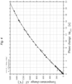
- An example of a temperature monitoring during fiber splicing is shown in FIG 5 .
- the optical fiber material should be optically transparent/semitransparent in at least one wavelength region.
- the wavelength region should be transparent or semitransparent within the temperature range of interest.
- the fiber cross section should be circular symmetric, i.e in the form of a cylinder. When heated, the optical fiber changes in dimension and refractive index due to thermal expansion and the thermo-optical properties of the material.
- the microcavity interferometer consists of the optical microcavity (i.e. the optical fiber being spliced), a light source (e.g. a laser), optical components (e.g. mirrors, lenses, beam splitters and polarization optics), detector components (e.g. homodyne detection, hereodyne detection, spectral detection, or imaging/fringe analysis), and equipment for processing, presenting, and/or storing the data/results obtained from the measurement.
- a light source e.g. a laser
- optical components e.g. mirrors, lenses, beam splitters and polarization optics
- detector components e.g. homodyne detection, hereodyne detection, spectral detection, or imaging/fringe analysis
- the light source should have a wavelength/wavelengths overlapping with wavelength region of transparency/ semitransparency of the optical fiber, and a coherence length of the order of, or greater than the diameter of the optical fiber.
- FIG 2a is a schematic representation of a Fabry Perot type microcavity interferometer (FP interferometer).
- the FP interferometer (110) consists of a light source (111) in the form of a laser, a beam splitter (119), and a focusing lens (120) for focusing the beam (121) on the optical fiber microcavity (103,104).
- FIG 3a is a schematic representation of a Mach Zehnder type microcavity interferometer (MZ interferometer).
- the MZ interferometer (110') consists of a light source (111') in the form of a laser and a focusing lens (122) for focusing the beam (123) on the optical fiber microcavity (103,104).
- the optical interferometers of the invention is based on a micro-cavity design having circular symmetry. Impinging light will be partially reflected and scattered at the interfaces of the micro-cavity due to changes of the refractive index between the ambient air and the micro-cavity, i.e. Fresnel reflections.
- the modes can be made to interfere at a position outside the cavity, as shown in FIG 2b for a FP interferometer and in FIG 3b for an MZ interferometer.
- the recombined beams will interfere constructively or destructively depending on the phase difference between the two paths of the interferometer.
- OPL (length) x (refractive index)
- Using a focused beam also ensures that the phase front of the light is parallel with the surface of reflection. This is true specifically for the FP interferometer ( FIG 2a ).
- the phase front of the optical beam becomes parallel to the surface of the cylinder/sphere as in the case of a traditional Fabry-Perot interferometer.
- incoming light is partially reflected at the surface (surface reflection), while part of the light is transmitted/refracted and can be reflected further within the cavity before exiting the cavity, as shown in FIG 2b .
- the surface reflection and the 3rd order refracting beam are co-aligned and can be made to interfere.
- the angle is ⁇ 94 deg.
- Example 1 Temperature as a function of phase
- FIG 4 shows the measured temperature as a function of phase when an SM fiber with a diameter of 125 ⁇ m was heated using a carbon-dioxide laser.
- the measurement was performed by (i) measuring the change in phase by interferometry, using the optical fiber as the optical microcavity, and (ii) simultaneously measuring the temperature of the optical fiber, at the same position, using a previously calibrated high-temperature stable fiber Bragg grating as described in US patent 6334018B1 (Optical material having periodically varying refractive index and method of making). Localized heating of the grating and interferometer optical microcavity was performed by laser irradiation using a carbon-dioxide laser operating at a wavelength of 10.6 ⁇ m.
- phase extraction was performed using fringe counting with signal detection comprised of recording the quadrature signals from the interferometer optical microcavity followed by phase unwrapping.
- a high temperature stable optical fiber Bragg grating was positioned at the same location as the interferometer optical microcavity.
- the fiber Bragg grating was 1 mm long with a Bragg wavelength at room temperature of 1542 nm.
- the peak wavelength of the grating was monitored in reflection using a white light source, an optical fiber circulator and an optical spectrum analyzer. Heating was performed by irradiating the fiber for a duration of two seconds.
- the data points in figure 4 include heating and cooling dynamics of six separate measurements using different power levels.
- FIG 5 is a diagram showing the measured temperature changes in an SM optical fiber during and directly after heating of the optical fiber using the electric arc discharge from an Ericsson FSU-850 fusion splicer. The measurement was performed using standard parameter settings for SM optical fiber splicing.
Landscapes
- Physics & Mathematics (AREA)
- General Physics & Mathematics (AREA)
- Engineering & Computer Science (AREA)
- Plasma & Fusion (AREA)
- Optics & Photonics (AREA)
- Chemical & Material Sciences (AREA)
- Analytical Chemistry (AREA)
- Measuring Temperature Or Quantity Of Heat (AREA)
Claims (11)
- Verfahren zur Messung der Temperatur von Faserenden (103, 104) von Glasfasern während des Schmelzspleißens oder der thermischen Verarbeitung, das durch eine Schmelzspleißvorrichtung (100, 100') durchgeführt wird, gekennzeichnet durch:a) Messen, unter Verwendung eines interferometrischen Verfahrens, einer Änderung einer optischen Weglänge in einer Glasfaser aufgrund von temperaturabhängigen Eigenschaften der Glasfaser während des Schmelzspleißens oder der thermischen Verarbeitung und wobei die Glasfaser, die selbst einen kreisförmigen Querschnitt aufweist, als optische Mikrokavität dient; undb) Bestimmen der Temperatur der Faserenden (103, 104) der Glasfaser basierend auf den gemessenen Änderungen der optischen Weglänge in der optischen Mikrokavität.
- Verfahren nach Anspruch 1, wobei die Glasfaser aus einem Material besteht, das aus der Gruppe bestehend aus Glas auf Kieselsäurebasis, Telluridglas, Chalkogenidglas, Fluoridglas, Saphirkristall, Quarzkristall und kristallinem Silizium ausgewählt ist.
- Verfahren nach einem der vorhergehenden Ansprüche, wobei die temperaturabhängigen Eigenschaften der Glasfaser aus der Gruppe bestehend aus thermischer Ausdehnung und Brechungsindex ausgewählt sind.
- Verfahren nach einem der vorhergehenden Ansprüche, wobei die gemessene Temperatur im Bereich von 100 °C bis 3000 °C, bevorzugt im Bereich von 1000 °C bis 3000 °C, liegt.
- Verfahren nach einem der vorhergehenden Ansprüche, wobei das interferometrische Verfahren das Messen der Änderung einer optischen Weglänge unter Verwendung eines Interferometers des Fabry-Perot- oder Mach-Zehnder-Typs umfasst.
- Verfahren nach einem der vorhergehenden Ansprüche, wobei das Verfahren ferner den folgenden Schritt umfasst:
c) Verwenden der in Schritt b) bestimmte Temperatur als Rückmeldung beim Spleißen, um eine steuerbare Temperatur zu ermöglichen. - Verfahren nach einem der vorhergehenden Ansprüche, wobei das Verfahren ferner den folgenden Schritt umfasst:
d) Analysieren der Glasfaser nach dem Schmelzspleißen unter Verwendung eines interferometrischen Verfahrens zur Bestimmung der Qualität des Spleißes durch Detektion von Variationen des Durchmessers oder des Brechungsindex der Glasfaser. - Schmelzspleißvorrichtung (100, 100') zum Verschmelzen oder Verschweißen von Glasfasern miteinander, wobei die Vorrichtung Mittel zum Messen der Temperatur von Faserenden (103, 104) von Glasfasern während des Schmelzspleißens oder der thermischen Verarbeitung umfasst, dadurch gekennzeichnet, dass:die Mittel ein optisches Mikrokavitäts-Interferometer (110, 110') umfassen, das konfiguriert ist, um eine Änderung einer optischen Weglänge in einer optischen Mikrokavität aufgrund von temperaturabhängigen Eigenschaften der optischen Mikrokavität zu messen, unddas optische Mikrokavitäts-Interferometer (110, 110') angeordnet ist, um eine Glasfaser zu verwenden, die in der Schmelzspleißvorrichtung (100, 100') einem Schmelzspleißen oder einer thermischen Verarbeitung unterzogen wird, und wobei die Glasfaser, die selbst einen kreisförmigen Querschnitt aufweist, als optische Mikrokavität dient.
- Schmelzspleißvorrichtung (100, 100') nach Anspruch 8, wobei das optische Mikrokavitäts-Interferometer (110, 110') ein Mikrokavitäts-Interferometer des Fabry-Perot- oder Mach-Zehnder-Typs ist.
- Schmelzspleißvorrichtung (100, 100') nach Anspruch 8 oder 9, wobei die Vorrichtung konfiguriert ist, um die gemessene Temperatur als Rückmeldung während des Spleißens zu verwenden, um eine steuerbare Temperatur zu ermöglichen.
- Verwendung einer Glasfaser, die selbst einen kreisförmigen Querschnitt aufweist, um als optische Mikrokavität in einem optischen Mikrokavitäts-Interferometer (110, 110') zu dienen, durch eine Schmelzspleißvorrichtung (100, 100') nach einem der Ansprüche 8-10 zum Messen der Temperatur von Faserenden (103, 104) der Glasfaser während des Schmelzspleißens oder der thermischen Verarbeitung der Glasfaser.
Applications Claiming Priority (2)
| Application Number | Priority Date | Filing Date | Title |
|---|---|---|---|
| SE1851411A SE542745C2 (en) | 2018-11-13 | 2018-11-13 | Method and apparatus for temperature measurement in optical fiber fusion splicing |
| PCT/SE2019/051133 WO2020101555A1 (en) | 2018-11-13 | 2019-11-08 | Method and apparatus for temperature measurement in optical fiber fusion splicing |
Publications (4)
| Publication Number | Publication Date |
|---|---|
| EP3881111A1 EP3881111A1 (de) | 2021-09-22 |
| EP3881111A4 EP3881111A4 (de) | 2022-08-17 |
| EP3881111C0 EP3881111C0 (de) | 2024-10-23 |
| EP3881111B1 true EP3881111B1 (de) | 2024-10-23 |
Family
ID=70730848
Family Applications (1)
| Application Number | Title | Priority Date | Filing Date |
|---|---|---|---|
| EP19883428.5A Active EP3881111B1 (de) | 2018-11-13 | 2019-11-08 | Verfahren und vorrichtung zur temperaturmessung bei einer glasfaserschmelzspleissung |
Country Status (4)
| Country | Link |
|---|---|
| US (1) | US11976982B2 (de) |
| EP (1) | EP3881111B1 (de) |
| SE (1) | SE542745C2 (de) |
| WO (1) | WO2020101555A1 (de) |
Families Citing this family (1)
| Publication number | Priority date | Publication date | Assignee | Title |
|---|---|---|---|---|
| CN114414134B (zh) * | 2022-01-21 | 2022-11-29 | 吉林大学 | 一种基于pdms膜和游标效应增敏的光纤液压传感器 |
Family Cites Families (12)
| Publication number | Priority date | Publication date | Assignee | Title |
|---|---|---|---|---|
| US3982816A (en) * | 1974-06-21 | 1976-09-28 | Western Electric Company, Inc. | Method for measuring the parameters of optical fibers |
| HU186688B (en) * | 1983-04-18 | 1985-09-30 | Budapesti Mueszaki Egyetem | Method for measuring the diameter and/or diameter variation of glass fiber on the basis of resonance of fabry-perot and device for carrying out the metod |
| JPS6079237A (ja) * | 1983-10-07 | 1985-05-07 | Hitachi Ltd | 相対温度測定装置 |
| US5381229A (en) * | 1991-03-29 | 1995-01-10 | Center For Innovative Technology | Sapphire optical fiber interferometer |
| SE505782C2 (sv) * | 1995-04-28 | 1997-10-06 | Ericsson Telefon Ab L M | Förfarande för styrning av temperatur under en fiberskarvningsprocess samt förfarande och anordning för att tillverka en optisk fiberdämpningsanordning |
| JP4429540B2 (ja) * | 2001-03-15 | 2010-03-10 | 古河電気工業株式会社 | 光ファイバの融着接続方法 |
| US7343258B2 (en) * | 2002-12-05 | 2008-03-11 | Telefonaktiebolaget Lm Ericsson (Publ) | Fusion temperature calibration |
| DE102006031078A1 (de) * | 2006-07-05 | 2008-01-10 | CCS Technology, Inc., Wilmington | Verfahren zum Betreiben einer Vorrichtung zum Spleißen von Lichtwellenleitern |
| US8478092B2 (en) * | 2009-11-02 | 2013-07-02 | The Hong Kong Polytechnic University | In-line single fiber Mach-Zehnder interferometer |
| US20140363118A1 (en) * | 2013-06-07 | 2014-12-11 | The Hong Kong Polytechnic University | Microfiber device with enclosed inner cavity |
| CN105115623B (zh) * | 2015-08-12 | 2017-12-01 | 天津大学 | 基于迈克尔逊干涉理论的微型光纤高温传感器及制作方法 |
| JP6317388B2 (ja) * | 2016-04-18 | 2018-04-25 | 株式会社フジクラ | 光ファイバ融着接続構造及びレーザ装置の製造方法 |
-
2018
- 2018-11-13 SE SE1851411A patent/SE542745C2/en unknown
-
2019
- 2019-11-08 EP EP19883428.5A patent/EP3881111B1/de active Active
- 2019-11-08 WO PCT/SE2019/051133 patent/WO2020101555A1/en not_active Ceased
- 2019-11-08 US US17/292,422 patent/US11976982B2/en active Active
Also Published As
| Publication number | Publication date |
|---|---|
| US11976982B2 (en) | 2024-05-07 |
| EP3881111A4 (de) | 2022-08-17 |
| SE542745C2 (en) | 2020-07-07 |
| EP3881111C0 (de) | 2024-10-23 |
| EP3881111A1 (de) | 2021-09-22 |
| SE1851411A1 (en) | 2020-05-14 |
| US20220011175A1 (en) | 2022-01-13 |
| WO2020101555A1 (en) | 2020-05-22 |
Similar Documents
| Publication | Publication Date | Title |
|---|---|---|
| Zhao et al. | Hybrid fiber-optic sensor for seawater temperature and salinity simultaneous measurements | |
| Tsai et al. | A novel structure for the intrinsic Fabry-Perot fiber-optic temperature sensor | |
| Wang et al. | High sensitivity humidity fiber-optic sensor based on all-agar Fabry–Perot interferometer | |
| Yuan et al. | Cascaded vernier effect optic fiber temperature sensor with DSHF-Based MZI and FPI | |
| CN103940355A (zh) | 强度调制型光纤迈克尔逊应变传感器及制作方法 | |
| CN102183490A (zh) | 光纤全息干涉测量装置 | |
| CN107505065A (zh) | 高阶模f‑p干涉高温探针传感器的制作方法与装置 | |
| Yang et al. | Hourglass-shaped fiber-optic Mach-Zehnder interferometer for pressure sensing | |
| Jauregui-Vazquez et al. | Modified all-fiber Fabry–Perot interferometer and its refractive index, load, and temperature analyses | |
| EP3881111B1 (de) | Verfahren und vorrichtung zur temperaturmessung bei einer glasfaserschmelzspleissung | |
| CN109682778A (zh) | 飞秒激光制备纤芯失配型fbg温度折射率测量方法 | |
| Wei et al. | Directional bending sensor and multiparameter sensor based on D-core multimode fiber | |
| CN109655176A (zh) | 一种基于空腔填充型微结构光纤干涉仪的高精度温度探头 | |
| CN112762983A (zh) | 一种飞秒激光直写lfpg结合光纤mzi结构的双参数测试方法 | |
| Harvey et al. | Mach-Zehnder interferometer for in-situ non-contact temperature monitoring during thermal processing of an optical fibre | |
| CN108195483A (zh) | 一种实现温度和应变测量的光纤f-p传感器制作方法 | |
| Fiorin et al. | FBG-assisted micro-channel for refractive index measurements | |
| CN109682779A (zh) | 飞秒激光制备纤芯失配型fbg温度应变折射率测量方法 | |
| CN216144696U (zh) | 一种液滴型空气腔的光纤马赫-曾德尔折射率传感器 | |
| Dash et al. | Enlarge-tapered, micro-air channeled cavity for refractive index sensing in SMF | |
| Liu et al. | HCPCF-based in-line fiber Fabry-Perot refractometer and high sensitivity signal processing method | |
| KR102099224B1 (ko) | 폴리머가 코팅된 광섬유 끝단을 사용하는 온도센서의 제조방법, 폴리머가 코팅된 광섬유 끝단을 사용하는 온도센서를 포함하는 온도 측정 시스템 및 이를 이용한 온도 측정방법 | |
| KR102596779B1 (ko) | 마이크로 옵틱 마하젠더 간섭계 기반의 3d 프린팅 구조물의 광학특성 측정 방법 및 장치 | |
| Jiang et al. | Temperature insensitive fully open cavity fiber inline Fabry–Perot interferometer optofluidic sensor with microlens enhanced visibility | |
| Meng et al. | Hybrid fiber interferometer for simultaneous measurement of displacement and temperature |
Legal Events
| Date | Code | Title | Description |
|---|---|---|---|
| STAA | Information on the status of an ep patent application or granted ep patent |
Free format text: STATUS: THE INTERNATIONAL PUBLICATION HAS BEEN MADE |
|
| PUAI | Public reference made under article 153(3) epc to a published international application that has entered the european phase |
Free format text: ORIGINAL CODE: 0009012 |
|
| STAA | Information on the status of an ep patent application or granted ep patent |
Free format text: STATUS: REQUEST FOR EXAMINATION WAS MADE |
|
| 17P | Request for examination filed |
Effective date: 20210507 |
|
| AK | Designated contracting states |
Kind code of ref document: A1 Designated state(s): AL AT BE BG CH CY CZ DE DK EE ES FI FR GB GR HR HU IE IS IT LI LT LU LV MC MK MT NL NO PL PT RO RS SE SI SK SM TR |
|
| DAV | Request for validation of the european patent (deleted) | ||
| DAX | Request for extension of the european patent (deleted) | ||
| A4 | Supplementary search report drawn up and despatched |
Effective date: 20220715 |
|
| RIC1 | Information provided on ipc code assigned before grant |
Ipc: G01K 11/00 20060101ALI20220711BHEP Ipc: G01K 5/48 20060101ALI20220711BHEP Ipc: G01K 11/32 20210101ALI20220711BHEP Ipc: G01D 5/353 20060101ALI20220711BHEP Ipc: G02B 6/255 20060101AFI20220711BHEP |
|
| GRAP | Despatch of communication of intention to grant a patent |
Free format text: ORIGINAL CODE: EPIDOSNIGR1 |
|
| STAA | Information on the status of an ep patent application or granted ep patent |
Free format text: STATUS: GRANT OF PATENT IS INTENDED |
|
| INTG | Intention to grant announced |
Effective date: 20240621 |
|
| GRAS | Grant fee paid |
Free format text: ORIGINAL CODE: EPIDOSNIGR3 |
|
| GRAA | (expected) grant |
Free format text: ORIGINAL CODE: 0009210 |
|
| STAA | Information on the status of an ep patent application or granted ep patent |
Free format text: STATUS: THE PATENT HAS BEEN GRANTED |
|
| AK | Designated contracting states |
Kind code of ref document: B1 Designated state(s): AL AT BE BG CH CY CZ DE DK EE ES FI FR GB GR HR HU IE IS IT LI LT LU LV MC MK MT NL NO PL PT RO RS SE SI SK SM TR |
|
| REG | Reference to a national code |
Ref country code: GB Ref legal event code: FG4D |
|
| REG | Reference to a national code |
Ref country code: CH Ref legal event code: EP |
|
| REG | Reference to a national code |
Ref country code: DE Ref legal event code: R096 Ref document number: 602019060929 Country of ref document: DE |
|
| REG | Reference to a national code |
Ref country code: IE Ref legal event code: FG4D |
|
| U01 | Request for unitary effect filed |
Effective date: 20241122 |
|
| U07 | Unitary effect registered |
Designated state(s): AT BE BG DE DK EE FI FR IT LT LU LV MT NL PT RO SE SI Effective date: 20241129 |
|
| U20 | Renewal fee for the european patent with unitary effect paid |
Year of fee payment: 6 Effective date: 20241127 |
|
| PG25 | Lapsed in a contracting state [announced via postgrant information from national office to epo] |
Ref country code: IS Free format text: LAPSE BECAUSE OF FAILURE TO SUBMIT A TRANSLATION OF THE DESCRIPTION OR TO PAY THE FEE WITHIN THE PRESCRIBED TIME-LIMIT Effective date: 20250223 Ref country code: HR Free format text: LAPSE BECAUSE OF FAILURE TO SUBMIT A TRANSLATION OF THE DESCRIPTION OR TO PAY THE FEE WITHIN THE PRESCRIBED TIME-LIMIT Effective date: 20241023 |
|
| PG25 | Lapsed in a contracting state [announced via postgrant information from national office to epo] |
Ref country code: ES Free format text: LAPSE BECAUSE OF FAILURE TO SUBMIT A TRANSLATION OF THE DESCRIPTION OR TO PAY THE FEE WITHIN THE PRESCRIBED TIME-LIMIT Effective date: 20241023 |
|
| PG25 | Lapsed in a contracting state [announced via postgrant information from national office to epo] |
Ref country code: NO Free format text: LAPSE BECAUSE OF FAILURE TO SUBMIT A TRANSLATION OF THE DESCRIPTION OR TO PAY THE FEE WITHIN THE PRESCRIBED TIME-LIMIT Effective date: 20250123 |
|
| PG25 | Lapsed in a contracting state [announced via postgrant information from national office to epo] |
Ref country code: GR Free format text: LAPSE BECAUSE OF FAILURE TO SUBMIT A TRANSLATION OF THE DESCRIPTION OR TO PAY THE FEE WITHIN THE PRESCRIBED TIME-LIMIT Effective date: 20250124 |
|
| PG25 | Lapsed in a contracting state [announced via postgrant information from national office to epo] |
Ref country code: PL Free format text: LAPSE BECAUSE OF FAILURE TO SUBMIT A TRANSLATION OF THE DESCRIPTION OR TO PAY THE FEE WITHIN THE PRESCRIBED TIME-LIMIT Effective date: 20241023 |
|
| PG25 | Lapsed in a contracting state [announced via postgrant information from national office to epo] |
Ref country code: RS Free format text: LAPSE BECAUSE OF FAILURE TO SUBMIT A TRANSLATION OF THE DESCRIPTION OR TO PAY THE FEE WITHIN THE PRESCRIBED TIME-LIMIT Effective date: 20250123 |
|
| REG | Reference to a national code |
Ref country code: CH Ref legal event code: PL |
|
| PG25 | Lapsed in a contracting state [announced via postgrant information from national office to epo] |
Ref country code: SM Free format text: LAPSE BECAUSE OF FAILURE TO SUBMIT A TRANSLATION OF THE DESCRIPTION OR TO PAY THE FEE WITHIN THE PRESCRIBED TIME-LIMIT Effective date: 20241023 |
|
| PG25 | Lapsed in a contracting state [announced via postgrant information from national office to epo] |
Ref country code: MC Free format text: LAPSE BECAUSE OF FAILURE TO SUBMIT A TRANSLATION OF THE DESCRIPTION OR TO PAY THE FEE WITHIN THE PRESCRIBED TIME-LIMIT Effective date: 20241023 |
|
| REG | Reference to a national code |
Ref country code: CH Ref legal event code: PL |
|
| PG25 | Lapsed in a contracting state [announced via postgrant information from national office to epo] |
Ref country code: CH Free format text: LAPSE BECAUSE OF NON-PAYMENT OF DUE FEES Effective date: 20241130 |
|
| PG25 | Lapsed in a contracting state [announced via postgrant information from national office to epo] |
Ref country code: SK Free format text: LAPSE BECAUSE OF FAILURE TO SUBMIT A TRANSLATION OF THE DESCRIPTION OR TO PAY THE FEE WITHIN THE PRESCRIBED TIME-LIMIT Effective date: 20241023 |
|
| PG25 | Lapsed in a contracting state [announced via postgrant information from national office to epo] |
Ref country code: CZ Free format text: LAPSE BECAUSE OF FAILURE TO SUBMIT A TRANSLATION OF THE DESCRIPTION OR TO PAY THE FEE WITHIN THE PRESCRIBED TIME-LIMIT Effective date: 20241023 |
|
| PLBE | No opposition filed within time limit |
Free format text: ORIGINAL CODE: 0009261 |
|
| STAA | Information on the status of an ep patent application or granted ep patent |
Free format text: STATUS: NO OPPOSITION FILED WITHIN TIME LIMIT |
|
| 26N | No opposition filed |
Effective date: 20250724 |
|
| PG25 | Lapsed in a contracting state [announced via postgrant information from national office to epo] |
Ref country code: IE Free format text: LAPSE BECAUSE OF NON-PAYMENT OF DUE FEES Effective date: 20241108 |
|
| U20 | Renewal fee for the european patent with unitary effect paid |
Year of fee payment: 7 Effective date: 20251126 |
|
| PGFP | Annual fee paid to national office [announced via postgrant information from national office to epo] |
Ref country code: GB Payment date: 20251125 Year of fee payment: 7 |
|
| PGFP | Annual fee paid to national office [announced via postgrant information from national office to epo] |
Ref country code: TR Payment date: 20251106 Year of fee payment: 7 |
|
| PG25 | Lapsed in a contracting state [announced via postgrant information from national office to epo] |
Ref country code: HU Free format text: LAPSE BECAUSE OF FAILURE TO SUBMIT A TRANSLATION OF THE DESCRIPTION OR TO PAY THE FEE WITHIN THE PRESCRIBED TIME-LIMIT; INVALID AB INITIO Effective date: 20191108 |