EP3880523B1 - Single-piece support for fixing a safety belt winder to a quarter panel lining of a motor vehicle - Google Patents
Single-piece support for fixing a safety belt winder to a quarter panel lining of a motor vehicle Download PDFInfo
- Publication number
- EP3880523B1 EP3880523B1 EP19816831.2A EP19816831A EP3880523B1 EP 3880523 B1 EP3880523 B1 EP 3880523B1 EP 19816831 A EP19816831 A EP 19816831A EP 3880523 B1 EP3880523 B1 EP 3880523B1
- Authority
- EP
- European Patent Office
- Prior art keywords
- support
- side walls
- wall
- junction
- extension
- Prior art date
- Legal status (The legal status is an assumption and is not a legal conclusion. Google has not performed a legal analysis and makes no representation as to the accuracy of the status listed.)
- Active
Links
- 239000002184 metal Substances 0.000 claims description 5
- 238000000034 method Methods 0.000 description 6
- 238000007373 indentation Methods 0.000 description 5
- 238000005304 joining Methods 0.000 description 5
- 238000005452 bending Methods 0.000 description 4
- 238000005520 cutting process Methods 0.000 description 4
- 230000003014 reinforcing effect Effects 0.000 description 4
- 238000007493 shaping process Methods 0.000 description 4
- 238000003466 welding Methods 0.000 description 4
- 238000012423 maintenance Methods 0.000 description 3
- 239000000463 material Substances 0.000 description 3
- 230000002787 reinforcement Effects 0.000 description 3
- 230000000694 effects Effects 0.000 description 2
- 235000004522 Pentaglottis sempervirens Nutrition 0.000 description 1
- 230000001939 inductive effect Effects 0.000 description 1
- 238000009434 installation Methods 0.000 description 1
- 230000002427 irreversible effect Effects 0.000 description 1
- 238000004519 manufacturing process Methods 0.000 description 1
- 230000000135 prohibitive effect Effects 0.000 description 1
- 238000000926 separation method Methods 0.000 description 1
- 230000035939 shock Effects 0.000 description 1
- 125000006850 spacer group Chemical group 0.000 description 1
Images

Classifications
-
- B—PERFORMING OPERATIONS; TRANSPORTING
- B60—VEHICLES IN GENERAL
- B60R—VEHICLES, VEHICLE FITTINGS, OR VEHICLE PARTS, NOT OTHERWISE PROVIDED FOR
- B60R22/00—Safety belts or body harnesses in vehicles
- B60R22/34—Belt retractors, e.g. reels
-
- B—PERFORMING OPERATIONS; TRANSPORTING
- B60—VEHICLES IN GENERAL
- B60R—VEHICLES, VEHICLE FITTINGS, OR VEHICLE PARTS, NOT OTHERWISE PROVIDED FOR
- B60R22/00—Safety belts or body harnesses in vehicles
- B60R22/18—Anchoring devices
- B60R22/24—Anchoring devices secured to the side, door, or roof of the vehicle
-
- B—PERFORMING OPERATIONS; TRANSPORTING
- B60—VEHICLES IN GENERAL
- B60R—VEHICLES, VEHICLE FITTINGS, OR VEHICLE PARTS, NOT OTHERWISE PROVIDED FOR
- B60R22/00—Safety belts or body harnesses in vehicles
- B60R22/34—Belt retractors, e.g. reels
- B60R2022/3402—Retractor casings; Mounting thereof
Landscapes
- Engineering & Computer Science (AREA)
- Mechanical Engineering (AREA)
- Automotive Seat Belt Assembly (AREA)
- Body Structure For Vehicles (AREA)
Description
La présente invention relève du domaine des véhicules automobiles et plus particulièrement des modalités de protection des passagers du véhicule en cas d'accident. L'invention porte plus précisément sur des modalités de montage d'un enrouleur d'une ceinture de sécurité sur la caisse d'un véhicule automobile.The present invention relates to the field of motor vehicles and more particularly to methods of protecting the passengers of the vehicle in the event of an accident. The invention relates more specifically to methods of mounting a retractor for a seat belt on the body of a motor vehicle.
Les véhicules automobiles comprennent une caisse ménageant une armature robuste sur laquelle sont installés divers équipements du véhicule. L'armature est revêtue d'un habillage comprenant des panneaux qui sont fixés sur la caisse, dont notamment des panneaux latéraux désignés par custodes. Les custodes sont couramment habillées de doublures qui sont disposées vers l'intérieur de la caisse et qui peuvent être utilisées pour le montage de divers équipements du véhicule sur la caisse.Motor vehicles include a body providing a sturdy frame on which are installed various equipment of the vehicle. The frame is coated with a covering comprising panels which are fixed to the body, including in particular side panels designated as rear quarter panels. The quarter panels are commonly fitted with liners which are arranged towards the inside of the body and which can be used for mounting various vehicle equipment on the body.
Parmi les équipements du véhicule montés sur la caisse, certains relèvent de la protection des passagers en cas de choc subit par le véhicule. Tel est le cas d'un enrouleur d'une ceinture de sécurité dédiée au maintien d'un passager sur un siège du véhicule. L'enrouleur est agencé en dévidoir d'une réserve de la ceinture de sécurité et est placé à l'arrière d'un siège du véhicule, indifféremment un siège avant ou un siège arrière, en étant installé à l'un des côtés droit ou gauche de la caisse.Among the vehicle equipment mounted on the body, some relate to the protection of passengers in the event of an impact suffered by the vehicle. Such is the case of a retractor of a seat belt dedicated to maintaining a passenger on a seat of the vehicle. The reel is arranged as a reel for a spare seat belt and is placed at the rear of a seat of the vehicle, either a front seat or a rear seat, being installed on one of the right or left of the crate.
Les modalités de montage d'un enrouleur sur la caisse d'un véhicule automobile sont organisées en tenant de diverses contraintes. De telles contraintes relèvent par exemple de l'architecture de la caisse, notamment au regard du ou des éléments de carrosserie sur lequel l'enrouleur peut être fixé, de l'encombrement propre de l'enrouleur et/ou de son éventuelle mobilité sur la caisse pour ne pas entraver le confort d'utilisation de la ceinture par un passager. Il est aussi à tenir compte de la place disponible qui est restreinte dans l'environnement d'installation de l'enrouleur sur la caisse qui est fréquemment encombré par d'autres équipements et/ou éléments de carrosserie du véhicule. Il est aussi à tenir compte des contraintes économiques qui tendent à réduire les coûts de fabrication du véhicule, dans le contexte d'une concurrence économique notoirement sévère dans le domaine automobile qui peut rendre rédhibitoire une solution coûteuse de montage de l'enrouleur sur la caisse.The methods of mounting a retractor on the body of a motor vehicle are organized taking into account various constraints. Such constraints relate for example to the architecture of the body, in particular with regard to the bodywork element(s) on which the reel can be fixed, the size of the reel and/or its possible mobility on the body so as not to not hinder the comfort of use of the seat belt by a passenger. It is also necessary to take into account the available space which is restricted in the installation environment of the retractor on the body which is frequently encumbered by other equipment and/or bodywork elements of the vehicle. It is also necessary to take into account the economic constraints which tend to reduce the manufacturing costs of the vehicle, in the context of notoriously severe economic competition in the automotive field which can make a costly solution for mounting the retractor on the body prohibitive. .
Dans ce contexte de contraintes, les enrouleurs de ceintures de sécurité sont couramment fixés sur un support qui est lui-même fixé à au moins un élément de carrosserie constitutif de la caisse, potentiellement via un gousset, tel qu'un arc de pavillon, un montant et/ou une doublure de custode par exemple. L'agencement du support et ses modalités de montage sur la caisse sont alors organisés pour résister à l'encontre des efforts exercés par la ceinture et transmis au support via l'enrouleur, notamment en cas de choc subit par le véhicule.In this context of constraints, seat belt retractors are commonly fixed to a support which is itself fixed to at least one component bodywork of the body, potentially via a gusset, such as a roof arc, a pillar and/or quarter panel lining, for example. The arrangement of the support and its methods of mounting on the body are then organized to resist against the forces exerted by the belt and transmitted to the support via the retractor, in particular in the event of an impact suffered by the vehicle.
Le document (
Le document (The document (
Le document D3 (Document D3 (
Cependant, l'encombrement de l'enrouleur et/ou sa mise en mobilité sur le support implique fréquemment sa mise en saillie en direction de l'intérieur de la caisse, plus ou moins suivant l'extension transversale du véhicule. C'est pourquoi il est connu d'agencer le support en étrier qui délimite un logement de réception de l'enrouleur. L'enrouleur est fixé sur une paroi principale du support qui est perpendiculairement prolongée par des pattes latérales à bord rabattu qui s'étendent transversalement sur la caisse. Le support est fixé à au moins un élément de carrosserie de la caisse via le rabat que comportent les dites pattes latérales.However, the size of the retractor and/or its mobility on the support frequently involves its protrusion in the direction of the interior of the body, more or less along the transverse extension of the vehicle. This is why it is known to arrange the support in a stirrup which delimits a housing for receiving the winder. The reel is fixed to a main wall of the support which is extended perpendicularly by lateral tabs with folded edge which extend transversely on the body. The support is attached to at least one bodywork element of the body via the flap that the said side tabs have.
L'enrouleur est ainsi disposé transversalement sur la caisse entre la paroi principale du support et ledit montant. Ceci impose alors un accroissement de l'extension transversale des pattes latérales, au détriment de la résistance intrinsèque du support à l'encontre de sa déformation et donc de la qualité du montage de l'enrouleur sur la caisse.The retractor is thus arranged transversely on the body between the main wall of the support and said upright. This then imposes an increase in the transverse extension of the side tabs, to the detriment of the intrinsic resistance of the support against its deformation and therefore of the quality of the assembly of the retractor on the body.
Pour pallier à cet inconvénient, il est connu de ménager une fenêtre de passage de l'enrouleur à travers un montant sur lequel le support est fixé, ce qui permet de réduire l'extension transversale des pattes latérales tel qu'il ressort par exemple du document
Compte tenu de ce qui précède, l'invention a pour objet un support de montage d'un enrouleur d'une ceinture de sécurité sur la caisse d'un véhicule automobile. L'invention a aussi pour objet un véhicule automobile comprenant une caisse équipée d'au moins un enrouleur d'une ceinture de sécurité fixé à la caisse via un support conforme à l'invention.In view of the foregoing, the subject of the invention is a support for mounting a seat belt retractor on the body of a motor vehicle. The invention also relates to a motor vehicle comprising a body equipped with at least one reel of a seat belt fixed to the body via a support according to the invention.
Le but de l'invention est de procurer une fixation de qualité de l'enrouleur sur la caisse, en tenant notamment compte du contexte de contraintes et de difficultés à surmonter précédemment mentionnées.The object of the invention is to provide quality fastening of the retractor to the body, in particular taking into account the context of constraints and difficulties to be overcome mentioned above.
Il est plus spécifiquement recherché un support de l'enrouleur dont la robustesse intrinsèque lui confère une résistance satisfaisante à l'encontre des efforts qu'il est prévu de subir par suite de la mise en œuvre de l'enrouleur en cas de choc subit par le véhicule, et cela en évitant d'accroître significativement sa masse dans le contexte d'un allégement souhaitable du véhicule.What is more specifically sought is a support for the reel whose intrinsic robustness gives it satisfactory resistance against the forces that it is expected to undergo as a result of the implementation of the reel in the event of shock suffered by the vehicle, and this while avoiding significantly increasing its mass in the context of a desirable lightening of the vehicle.
Il est notamment recherché de conférer au support un caractère monobloc par façonnage d'une tôle d'épaisseur modérée, en organisant le support selon une architecture lui conférant une résistance intrinsèque satisfaisante à l'encontre de sa déformation.It is in particular sought to give the support a one-piece character by shaping a sheet of moderate thickness, by organizing the support according to an architecture giving it a satisfactory intrinsic resistance against its deformation.
Il est encore plus spécifiquement recherché de permettre un montage satisfaisant de l'enrouleur sur la caisse, via un support pouvant s'étendre significativement transversalement en direction de l'intérieur du véhicule compte tenu du volume de l'enrouleur logé à l'intérieur d'un espace ménagé par le support et/ou de son éventuelle montage mobile sur le support.It is even more specifically sought to allow satisfactory mounting of the reel on the body, via a support that can extend significantly transversely towards the interior of the vehicle given the volume of the reel housed inside. a space created by the support and/or its possible mobile mounting on the support.
Il est aussi plus spécifiquement recherché un support de l'enrouleur pouvant être obtenu à moindres coûts sans affecter la qualité du montage de l'enrouleur sur la caisse et/ou sans induire des difficultés d'installation de l'enrouleur sur la caisse qui seraient susceptibles d'accroître inopportunément les coûts de montage de l'enrouleur sur le véhicule.It is also more specifically sought a support for the reel that can be obtained at lower cost without affecting the quality of the assembly of the reel on the body and/or without inducing difficulties in installing the reel on the body which would be likely to inappropriately increase the costs of fitting the retractor to the vehicle.
Les buts visés par la présente invention sont atteints par un support d'un enrouleur d'une ceinture de sécurité pour un véhicule automobile comprenant les caractéristiques de la revendication 1.The aims targeted by the present invention are achieved by a support for a retractor of a safety belt for a motor vehicle comprising the characteristics of claim 1.
Ladite paroi de jonction est notamment fixée aux extrémités transversales des parois latérales qui sont transversalement situées à l'opposé d'une face ouverte d'un logement de réception de l'enrouleur ménagé par le support. Le dit logement est notamment délimité entre la paroi principale, les parois latérales et la paroi de jonction du support. Il est compris ici que ladite face ouverte du logement, ou autrement dit son débouché sur l'extérieur du support, est orientée sensiblement parallèlement à la paroi de jonction, en autorisant éventuellement une émergence de l'enrouleur verticalement hors du logement.Said junction wall is in particular fixed to the transverse ends of the side walls which are located transversely opposite an open face of a housing for receiving the winder formed by the support. Said housing is in particular delimited between the main wall, the side walls and the junction wall of the support. It is understood here that said open face of the housing, or in other words its outlet on the outside of the support, is oriented substantially parallel to the junction wall, possibly allowing the reel to emerge vertically out of the housing.
La paroi de jonction, issue du façonnage de la tôle, forme un organe de renfort du support apte à le maintenir en conformation à l'encontre de sa déformation lorsqu'il est soumis à des efforts transmis par l'enrouleur. Lorsque le support est soumis à de tels efforts, la paroi de jonction qui relie longitudinalement entre-elles les parois latérales, fait alors obstacle à leur affaissement transversal par flexion à leur bord jointif avec la paroi principale. Ceci a pour effet de maintenir en conformation le support nonobstant les efforts susceptibles d'être transmis au support par l'enrouleur, et finalement de procurer un maintien efficace en position de l'enrouleur sur la caisse.The junction wall, resulting from the shaping of the sheet, forms a reinforcing member of the support able to maintain it in conformation against its deformation when it is subjected to forces transmitted by the reel. When the support is subjected to such forces, the junction wall which longitudinally connects the side walls to one another then forms an obstacle to their transverse collapse by bending at their adjoining edge with the main wall. This has the effect of keeping the support in conformation notwithstanding the forces likely to be transmitted to the support by the retractor, and finally to provide effective maintenance in position of the retractor on the body.
Les bords de la paroi de jonction respectivement situés à ses extrémités longitudinales opposées suivant son plan d'extension, sont disjoints des bords des parois latérales qui leurs sont respectivement contigusThe edges of the junction wall respectively located at its opposite longitudinal ends along its extension plane, are separate from the edges of the side walls which are respectively contiguous to them.
De préférence, les parois latérales et la paroi de jonction sont en effet avantageusement formées conjointement par découpage et pliage de la tôle lors de son façonnage pour former le support.Preferably, the side walls and the junction wall are in fact advantageously formed together by cutting and bending the sheet during its shaping to form the support.
Plus particulièrement selon une forme de réalisation, les ruptures de jonction entre les dits bords de la paroi de jonction et lesdits bords contigus des parois latérales, sont ménagées par des échancrures formées à travers ladite tôle façonnée. Lesdites échancrures sont notamment formées par des découpes de la tôle réalisées lors de son façonnage.More particularly according to one embodiment, the breaks in the junction between the said edges of the junction wall and the said contiguous edges of the side walls are provided by indentations formed through the said shaped sheet. Said indentations are in particular formed by cutouts of the sheet made during its shaping.
Selon une forme de réalisation, lesdits deuxièmes rabats sont soudés aux parois latérales, indifféremment à leur face extérieure orientées vers l'extérieur du support ou à leur face intérieure orientée vers l'intérieur du logement.According to one embodiment, said second flaps are welded to the side walls, regardless of their outer face facing the outside of the support or their inner face facing the inside of the housing.
De préférence, la paroi de jonction comporte un troisième rabat participant de la deuxième interface de fixation du support sur la caisse. Ceci permet de conforter la fixation du support à la caisse, de préférence par soudage des premiers rabats et du troisième rabat sur au moins un élément de carrosserie constitutif de la caisse, tel qu'un gousset équipant un montant ou un arc de pavillon, le montant lui-même et/ou l'arc de pavillon lui-même, et/ou de préférence au moins une doublure de custode.Preferably, the junction wall comprises a third flap participating in the second interface for fixing the support to the body. This makes it possible to reinforce the attachment of the support to the body, preferably by welding the first flaps and the third flap onto at least one component bodywork element of the body, such as a gusset fitted to an upright or a roof arc, the upright itself and/or the roof arch itself, and/or preferably at least one quarter panel lining.
Selon une forme de réalisation, les bords de la paroi principale qui sont respectivement contigus avec les parois latérales et la paroi de jonction sont bombés. Lesdites conformations bombées des bords de la paroi principale forment des organes de renfort de la paroi principale vis-à-vis de son maintien en conformation dans son plan, et forment des organes de renfort de la jonction entre d'une part la paroi principale et d'autre part les parois latérales et la paroi de jonction à l'encontre de leur fléchissement.According to one embodiment, the edges of the main wall which are respectively contiguous with the side walls and the junction wall are curved. Said curved conformations of the edges of the main wall form reinforcing members of the main wall vis-à-vis its maintenance in conformation in its plane, and form reinforcing members of the junction between on the one hand the main wall and on the other hand the side walls and the junction wall against their bending.
Les coins arrondis sont contigus avec lesdites échancrures et procurent un renfort significatif du maintien en conformation de la paroi principale qui est susceptible d'être affaiblie par la rupture de continuité de matière entre la paroi de jonction et les parois latérales résultant de la présence des échancrures. Il est compris ici que ladite rupture de continuité de matière entre la paroi de jonction et les parois latérales est comprise par exclusion des deuxièmes rabats.The rounded corners are contiguous with said indentations and provide a significant reinforcement of the maintenance in conformation of the main wall which is likely to be weakened by the rupture of continuity of material between the junction wall and the side walls resulting from the presence of indentations . It is understood here that said break in continuity of material between the junction wall and the side walls is understood by excluding the second flaps.
Selon une forme de réalisation, les bords de jonction entre les parois latérales et les premiers rabats qui les prolongent respectivement sont renforcés par au moins un relief d'emboutissage de la tôle.According to one embodiment, the joining edges between the side walls and the first flaps which respectively extend them are reinforced by at least one stamping relief of the sheet.
De tels reliefs d'emboutissage ménagent des nervures saillantes, notamment vers l'extérieur du support en direction de la paroi principale. De préférence, le bord de jonction entre la paroi de jonction et le troisième rabat est aussi renforcé par au moins un relief d'emboutissage de la tôle. Les dits reliefs d'emboutissage sont de préférence ménagés par point de déformation de matière en chevauchement desdits bords de jonction. Plusieurs tels reliefs d'emboutissage sont de préférence répartis le long de chacun desdits bords de jonction, en étant plus ou moins proches les uns des autres et localisés sur le support selon l'orientation des composantes d'effort qu'il est prévu de subir.Such stamping reliefs provide projecting ribs, in particular towards the outside of the support in the direction of the main wall. Preferably, the junction edge between the junction wall and the third flap is also reinforced by at least one stamping relief of the sheet. Said stamping reliefs are preferably provided by material deformation point overlapping said junction edges. Several such stamping reliefs are preferably distributed along each of said joining edges, being more or less close to each other and located on the support according to the orientation of the stress components that are expected to be subjected .
Selon une forme de réalisation, les extensions transversales respectives des parois latérales et/ou leurs orientations respectives par rapport à la paroi principale sont différenciées.According to one embodiment, the respective transverse extensions of the side walls and/or their respective orientations with respect to the main wall are differentiated.
Il est compris ici que les dites extensions et/ou orientations respectives des parois latérales sont potentiellement identiques ou différentes selon la configuration de l'élément de carrosserie sur lequel le support est prévu d'être fixé, et cela sans affecter la résistance du support à l'encontre de sa déformation sous l'effet des efforts transmis par l'enrouleur. En d'autres termes, l'architecture générale du support autorise son adaptation aisée selon diverses configurations de l'élément de carrosserie sur lequel il est prévu d'être fixé, notamment par ajustement de l'extension transversale des parois latérales et cela sans affecter la qualité obtenue du montage de l'enrouleur sur la caisse.It is understood here that said respective extensions and/or orientations of the side walls are potentially identical or different depending on the configuration of the bodywork element on which the support is intended to be fixed, and this without affecting the resistance of the support to against its deformation under the effect of the forces transmitted by the reel. In other words, the general architecture of the support allows it to be easily adapted according to various configurations of the bodywork element on which it is intended to be fixed, in particular by adjusting the transverse extension of the side walls and this without affecting the quality obtained from mounting the reel on the body.
L'invention a aussi pour objet un véhicule automobile comprenant une caisse équipée d'au moins un enrouleur d'une ceinture de sécurité qui est monté sur un support fixé à au moins un élément de carrosserie que comprend la caisse. Selon l'invention, le véhicule est reconnaissable en ce que ledit support est conforme à l'invention.The invention also relates to a motor vehicle comprising a body equipped with at least one retractor of a seat belt which is mounted on a support fixed to at least one bodywork element that comprises the body. According to the invention, the vehicle is recognizable in that said support is in accordance with the invention.
L'invention sera mieux comprise à la lecture de la description détaillée qui suit d'un exemple de réalisation de la présente invention, en relation avec les figures suivantes :
- [
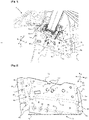
Fig. 1 ] Lafigure 1 est une illustration partielle en perspective d'une caisse d'un véhicule automobile, sur laquelle un enrouleur d'une ceinture de sécurité est monté via un support conforme à l'invention. - [
Fig. 2 ] Lafigure 2 est une illustration partielle en perspective dudit support représenté sur lafigure 1 , depuis l'extérieur du support en vue plongeante sur une paroi principale qu'il comprend. - [
Fig. 3 ] Lafigure 3 est une illustration partielle en perspective dudit support représenté sur lesfigures 1 et 2 , représentant les modalités d'assemblage entre une première paroi latérale et une paroi de jonction que comprend le support. - [
Fig. 4 ] Lafigure 4 est une illustration partielle en perspective dudit support représenté sur lesfigures 1 à 3 , représentant les modalités d'assemblage entre une deuxième paroi latérale et ladite paroi de jonction que comprend le support.
- [
Fig. 1 ] Thefigure 1 is a partial illustration in perspective of a body of a motor vehicle, on which a retractor of a seat belt is mounted via a support according to the invention. - [
Fig. 2 ] Thefigure 2 is a partial perspective illustration of said support shown in thefigure 1 , from the outside of the support in a bird's eye view of a main wall that it comprises. - [
Fig. 3 ] Thepicture 3 is a partial perspective illustration of said support shown in thefigures 1 and 2 , representing the methods of assembly between a first side wall and a junction wall that comprises the support. - [
Fig. 4 ] Thefigure 4 is a partial perspective illustration of said support shown in thefigures 1 to 3 , representing the methods of assembly between a second side wall and said junction wall that comprises the support.
Les figures et leurs descriptions détaillées non limitatives, exposent l'invention selon des modalités particulières qui ne sont pas restrictives quant à la portée de l'invention telle que définie par les revendications. Les figures et leurs descriptions détaillées d'un exemple de réalisation de l'invention peuvent servir à mieux la définir, si besoin en relation avec la description générale qui vient d'en être faite.The figures and their non-limiting detailed descriptions set out the invention according to specific terms which are not restrictive as to the scope of the invention as defined by the claims. The figures and their detailed descriptions of an exemplary embodiment of the invention can be used to better define it, if necessary in relation to the general description which has just been given.
Sur la
Sur les
Le support 3 comprend une paroi principale 5 s'étendant suivant un plan défini par les directions longitudinale L1 et verticale V1 d'extension du support 3. Lorsque le support 3 est installé sur la caisse 1 comme illustré sur la
Il est précisé ici que le terme sensiblement indique une approximation de la notion à laquelle elle se réfère. L'invention est applicable nonobstant une telle approximation signifiant que la notion considérée peut varier dans le cadre des règles délivrées par l'invention, notamment selon l'architecture propre du véhicule. Autrement dit, une notion à laquelle est affectée le terme sensiblement, ou autre terme apparenté, ne saurait être considérée au sens strict du terme.It is specified here that the term substantially indicates an approximation of the concept to which it refers. The invention is applicable notwithstanding such an approximation meaning that the notion considered may vary within the framework of the rules delivered by the invention, in particular according to the specific architecture of the vehicle. In other words, a notion to which the term substantially, or another related term, is assigned cannot be considered in the strict sense of the term.
L'enrouleur 2 est fixé à la paroi principale 5 du support 3 via une première interface de fixation 6a formée d'ouvertures 7 aptes à recevoir des organes de fixation, comme par exemple au moins un orifice et/ou au moins une échancrure aptes à coopérer avec un ou plusieurs organes de fixation pour maintenir l'enrouleur 2 sur le support 3. L'enrouleur 2 est susceptible d'être fixé sur le support 3 via la première interface de fixation 6a, par exemple par vissage, par emboîtement irréversible et/ou via un tourillon procurant un montage mobile en pivotement de l'enrouleur 2 sur le support 3. Lorsque l'enrouleur 2 est monté sur la caisse 1 via le support 3, celui-ci est transversalement T1 interposé entre la paroi principale 5 et l'élément de carrosserie 4 sur lequel le support 3 est fixé.The reel 2 is fixed to the
A cet effet, le support 3 comprend des parois latérales 8a, 8b qui sont respectivement ménagées aux extrémités longitudinales L1 opposées de la paroi principale 5. Les parois latérales 8a, 8b s'étendent individuellement suivant un plan sensiblement défini par les directions transversale T1 et verticale V1 d'extension du support 3, ou autrement dit sensiblement perpendiculairement au plan d'extension de la paroi principale 5. Au moins les parois latérales 8a, 8b ménagent ainsi des entretoises de séparation transversale T1 entre la paroi principale 5 et l'élément de carrosserie 4 sur lequel support 3 est fixé, pour permettre l'extension transversale T1 de l'enrouleur 2 entre la paroi principale 5 et ledit élément de carrosserie 4.To this end, the support 3 comprises
Les extensions transversales T1 et/ou les orientations respectives des parois latérales 8a, 8b sont susceptibles de varier de l'une à l'autre des parois latérales 8a, 8b, selon la configuration de l'élément de carrosserie 4 sur lequel le support 3 est fixé. Les parois latérales 8a, 8b peuvent être plus ou moins individuellement inclinées par rapport à la paroi principale 5 ou autrement dit par rapport à leur perpendicularité vis-à-vis du plan d'extension de la paroi principale 5, sans affecter la robustesse recherchée du support 3.The transverse extensions T1 and/or the respective orientations of the
Chacune des parois latérales 8a, 8b est munie d'un premier rabat 9a sensiblement orienté suivant un plan défini par les directions longitudinale L1 et verticale V1, en étant sensiblement orienté parallèlement au plan d'extension de la paroi principale 5. Les premiers rabats 9a sont tournés longitudinalement L1 vers l'extérieur du support 3 depuis leur bord de jonction aux parois latérales 8a, 8b, en participant d'une deuxième interface de fixation 6b du support 3 à l'élément de carrosserie 4 sur lequel le support 3 est prévu d'être fixé, avantageusement par soudage tel qu'illustré.Each of the
Les parois latérales 8a, 8b sont reliées entre elles par une paroi de jonction 10, à leur extrémité transversale T1 la plus éloignée de l'élément de carrosserie 4 sur lequel le support 3 est prévu d'être fixé. La paroi de jonction 10 s'étend suivant un plan défini par les directions longitudinale L1 et transversale T1 d'extension du support 3, sensiblement perpendiculairement au plan d'extension de la paroi principale 5.The
Un troisième rabat 9c globalement plan est ménagé le long de la paroi de jonction 10 à son bord 10a prévu d'être orienté vers l'élément de carrosserie 4 sur lequel le support 3 est destiné à être fixé. Le troisième rabat 9c s'étend sensiblement suivant les directions longitudinale L1 et verticale V1 d'extension du support 3, et participe de la deuxième interface de fixation 6b, en étant de préférence fixé par soudage sur l'élément de carrosserie 4. Les plans d'extension respectifs des premiers rabats 9a d'une part sont susceptibles d'être confondus ou d'être transversalement décalés l'un par rapport à l'autre, et d'autre part sont susceptibles d'être confondus ou d'être transversalement décalés par rapport au plan d'extension du troisième rabat 9c.A third generally flat flap 9c is provided along the
Le support 3 délimite ainsi un espace de réception de l'enrouleur 2, ou autrement dit un logement pour l'enrouleur 2, entre la paroi principale 5, les parois latérales 8a, 8b et la paroi de jonction 10. La paroi de jonction 10 étant ménagée sur le support 3 à son extrémité transversale T1 la plus éloignée de l'élément de carrosserie 4 sur lequel le support 3 est prévu d'être fixé, ledit espace est ouvert suivant un plan défini par les directions transversale T1 et longitudinale L1. Autrement dit, ledit logement comporte un débouché 11 orienté sensiblement parallèlement à la paroi de jonction 10, à travers lequel l'enrouleur 2 peut éventuellement émerger suivant l'extension verticale V1 du support 3.The support 3 thus delimits a space for receiving the reel 2, or in other words a housing for the reel 2, between the
La paroi principale 5, les parois latérales 8a, 8b, la paroi de jonction 10 et les rabats 9a, 9b, 9c dont les parois latérales 8a, 8b et la paroi de jonction 10 sont respectivement pourvues, sont formées par découpage puis par pliage de la tôle suivant les plans respectifs d'extension. Dans ce contexte, la paroi de jonction 10 est disjointe des parois latérales 8a, 8b, en raison de la présence d'échancrures 12 ménagées par découpage de la tôle entre la paroi de jonction 10 et respectivement chacune des parois latérales 8a, 8b, pour permettre de former le support 3 à partir du pliage de la tôle prédécoupée.The
Pour sa fixation aux parois latérales 8a, 8b, la paroi de jonction 10 est pourvue, à chacune de ses extrémités longitudinales opposées, d'un deuxième rabat 9b participant d'une troisième interface de fixation 6c de la paroi de jonction 10 aux parois latérales 8a, 8b. Les deuxièmes rabats 9b s'étendent en couverture des échancrures 12 depuis la paroi de jonction 10 vers les parois latérales 8a, 8b qui leurs sont respectivement affectées. Les deuxièmes rabats 9b sont fixés par soudage aux parois latérales 8a, 8b, de préférence à la face extérieure de l'un des deuxièmes rabats 9a comme représenté sur la
Les deuxièmes rabats 9b ménagent une doublure des parois latérales qui participe au renfort du support 3 à l'encontre de sa déformation et donc qui participe à sa résistance intrinsèque aux efforts transmis par l'enrouleur 2 qu'il est susceptible de supporter.The second flaps 9b provide a lining of the side walls which contributes to the reinforcement of the support 3 against its deformation and therefore which contributes to its intrinsic resistance to the forces transmitted by the retractor 2 that it is capable of supporting.
Pour conforter le renfort du support 3, les bords 5a de la paroi principale 5 qui sont respectivement contigus avec les parois latérales 8a, 8b et la paroi de jonction 10 sont significativement bombés. En outre une conformation significativement arrondie est conférée aux coins 5b de la paroi principale 5 qui sont situés dans ses zones de jonction avec la paroi de jonction 10 et les parois latérales 8a, 8b. Une telle conformation arrondie desdits coins est configurée pour renforcer le support 3 compte tenu de la contiguïté entre lesdits coins 5b et les échancrures 12 ménagées entre la paroi de jonction 10 et les parois latérales 8a, 8b.To reinforce the reinforcement of the support 3, the
De plus pour renforcer encore le support 3 dans sa zone de fixation à l'élément de carrosserie 4, les bords de jonction 13 entre les parois latérales 8a, 8b et les premiers rabats 9a, ainsi que le bord 10a de la paroi de jonction 10 la reliant avec le troisième rabat 9c, sont renforcés par au moins un relief 14 d'emboutissage de la tôle. Lesdits reliefs 14 forment des nervures de renfort qui s'étendent ponctuellement en chevauchement desdits bords de jonction 13, plusieurs reliefs 14 étant diversement répartis le long desdits bords de jonction 13. Les reliefs 14 sont ponctuellement localisés sur lesdits bords de jonction 13 à distance les uns des autres, en tenant compte des contraintes localisées que le support 3 est susceptible de subir via la deuxième interface de fixation 6b.In addition, to further reinforce the support 3 in its area of attachment to the bodywork element 4, the joining
Claims (8)
- Support (3) of a retractor (2) of a safety belt for a motor vehicle, the support (3) which extends along the three directions of an orthonormal mark which are identified in correspondence with the longitudinal (L1), transverse (T1) and vertical (V1) directions commonly used in the motor vehicle field to define the extension directions of a motor vehicle, being derived from a shaped sheet forming a generally flat main wall (5) of the support (3) which extends in its plane along longitudinal (L1) and vertical (V1) extension directions of the support (3) and which is provided with a first interface (6a) for fixing the reel (2) to the support (3), generally flat side walls (8a, 8b) extending substantially perpendicularly said main wall (5) to its longitudinally opposite edges (5a) (L1), extending in their plane substantially in the transverse (T1) and vertical (V1) directions of extension of the support (3), said side walls (8a, 8b) each comprising a first flap (9a) participating in a second interface (6b) for fixing the support (3) to a body (1) of the vehicle, said side walls (9a) 8a, 8b) being longitudinally connected to one another by a generally flat connecting wall (10) extending in the longitudinal (L1) and transverse (T1) direction of extension of the support (3), the edges of the connecting wall (10) respectively located at its longitudinally opposite ends (L1) in its extension plane being separated from the edges of the side walls (8a, 8b) which are respectively adjacent thereto, characterized in that the connecting wall (10) is extended substantially perpendicularly to its extension plane by second flaps (9b) which are provided at the longitudinally opposite ends from the junction wall (10) by forming a third fastening interface (6c) from the junction wall (10) to the side walls (8a, 8b) along their plane of extension, the corners (5b) of the main wall (5) located in its zones of junction with the junction wall (10) and the side walls (8a, 8b) being rounded.
- Support (3) according to claim 1, characterized in that the junction breaks between said edges of the junction wall (10) and said contiguous edges of the side walls (8a, 8b) are formed by notches (12) formed through said shaped sheet.
- Support (3) according to any one of claims 1 and 2, characterized in that said second flaps (9b) are welded to the side walls (8a, 8b).
- Support (3) according to any one of Claims 1 to 3, characterized in that the junction wall (10) comprises a third flap (9c) participating in the second interface (6b) for fixing the support (3) to the body.
- Support (3) according to one of Claims 1 to 4, characterized in that the edges (5a) of the main wall (5) which are respectively adjacent to the side walls (8a, 8b) and the connecting wall (10) are curved.
- Support (3) according to one of Claims 1 to 5, characterized in that the connecting edges (13) between the side walls (8a, 8b) and the first flaps (9a) which respectively extend them are reinforced by at least one stamping relief (14) of the sheet metal.
- Support (3) according to one of Claims 1 to 6, characterized in that the respective transverse extensions (T1) of the side walls (8a, 8b) and/or their respective orientations relative to the main wall (5) are differentiated.
- Motor vehicle comprising a body (1) equipped with at least one retractor (2) of a safety belt which is mounted on a support (3) fixed to at least one bodywork element (4) which comprises the body (1), characterized in that said support (3) is in accordance with any one of Claims 1 to 7.
Applications Claiming Priority (2)
| Application Number | Priority Date | Filing Date | Title |
|---|---|---|---|
| FR1871458A FR3088269B1 (en) | 2018-11-12 | 2018-11-12 | MONOBLOCK BRACKET FOR FIXING A SEAT BELT REEL ON A MOTOR VEHICLE CUSTOM LINING |
| PCT/FR2019/052573 WO2020099754A1 (en) | 2018-11-12 | 2019-10-29 | Single-piece support for fixing a safety belt winder to a quarter panel lining of a motor vehicle |
Publications (2)
| Publication Number | Publication Date |
|---|---|
| EP3880523A1 EP3880523A1 (en) | 2021-09-22 |
| EP3880523B1 true EP3880523B1 (en) | 2022-08-31 |
Family
ID=66041571
Family Applications (1)
| Application Number | Title | Priority Date | Filing Date |
|---|---|---|---|
| EP19816831.2A Active EP3880523B1 (en) | 2018-11-12 | 2019-10-29 | Single-piece support for fixing a safety belt winder to a quarter panel lining of a motor vehicle |
Country Status (5)
| Country | Link |
|---|---|
| EP (1) | EP3880523B1 (en) |
| ES (1) | ES2927593T3 (en) |
| FR (1) | FR3088269B1 (en) |
| MA (1) | MA54224A (en) |
| WO (1) | WO2020099754A1 (en) |
Family Cites Families (4)
| Publication number | Priority date | Publication date | Assignee | Title |
|---|---|---|---|---|
| JPS564986B2 (en) | 1973-08-20 | 1981-02-02 | ||
| CN203996103U (en) * | 2014-07-09 | 2014-12-10 | 广州汽车集团股份有限公司 | Automobile rear seat safety belt retractor mounting bracket, taking-up device assembly and auto body |
| DE102015004983A1 (en) * | 2015-04-18 | 2016-10-20 | GM Global Technology Operations LLC (n. d. Ges. d. Staates Delaware) | Carrier element for absorbing forces in a vehicle |
| CN206297527U (en) * | 2016-12-29 | 2017-07-04 | 长城汽车股份有限公司 | Webbing retractor mounting bracket, mounting structure and vehicle |
-
2018
- 2018-11-12 FR FR1871458A patent/FR3088269B1/en not_active Expired - Fee Related
-
2019
- 2019-10-29 MA MA054224A patent/MA54224A/en unknown
- 2019-10-29 ES ES19816831T patent/ES2927593T3/en active Active
- 2019-10-29 EP EP19816831.2A patent/EP3880523B1/en active Active
- 2019-10-29 WO PCT/FR2019/052573 patent/WO2020099754A1/en unknown
Also Published As
| Publication number | Publication date |
|---|---|
| MA54224A (en) | 2022-02-16 |
| EP3880523A1 (en) | 2021-09-22 |
| WO2020099754A1 (en) | 2020-05-22 |
| FR3088269A1 (en) | 2020-05-15 |
| FR3088269B1 (en) | 2020-10-23 |
| ES2927593T3 (en) | 2022-11-08 |
Similar Documents
| Publication | Publication Date | Title |
|---|---|---|
| EP1808362A2 (en) | vehicle body | |
| WO2019115461A1 (en) | Partition for a motor vehicle | |
| EP2080689B1 (en) | Side reinforcement device for the front block of an automobile and automobile equipped with such a device | |
| JP4239773B2 (en) | Car rear cargo compartment structure | |
| EP1184262B1 (en) | Body structure with reinforced suspension domes | |
| EP3880523B1 (en) | Single-piece support for fixing a safety belt winder to a quarter panel lining of a motor vehicle | |
| EP3099533B1 (en) | Device for attaching a sun visor and an airbag module | |
| EP2193064B1 (en) | Bodywork assembly for vehicle | |
| EP2867097B1 (en) | Motor vehicle comprising an additional reinforcement portion capable of guiding the deformation of the central pillar structure in case of a side impact | |
| EP2210782B1 (en) | Trim panel for a side door of a vehicle and vehicle door thus equipped | |
| EP3810461B1 (en) | Device for protecting a passenger side safety airbag for a motor vehicle | |
| WO2001019650A1 (en) | Assisting device for unfolding a motor vehicle inflatable airbag | |
| EP3810492A1 (en) | Motor vehicle body comprising a deformable element for attaching a receiving support of a safety belt winder | |
| EP2234865B1 (en) | Structure for automobile | |
| EP2443020B1 (en) | Center pillar for automobile frame reinforced against side impacts, and vehicle having such center pillar | |
| WO2010081949A1 (en) | Pedestrian impact absorber mobile knuckle mount | |
| EP1592603B1 (en) | Front pillar structure of a motor vehicle | |
| KR102567277B1 (en) | Structure of side sill for vehicle | |
| EP2132062B1 (en) | Assembly for attaching a safety bag module on a mechanically resistant structure of a dashboard | |
| FR3082819A1 (en) | AUTOMOTIVE VEHICLE BODY, PROVIDED WITH A SUPPORT FOR A REAR SEAT BELT WINDER WHICH INCORPORATES A BODY REINFORCEMENT WING | |
| EP3600974A1 (en) | Airbag device for interior trim element of a motor vehicle | |
| EP4065424B1 (en) | Deflector for a curtain airbag | |
| FR2959467A1 (en) | AIRBAG HOUSING OF AN AIRBAG SYSTEM AND AIRBAG SYSTEM | |
| EP1718100A1 (en) | Loudspeaker's grille arrangement | |
| WO2020016494A1 (en) | Protection assembly for a motor vehicle, provided with a curtain-type airbag cushion associated with a deflector |
Legal Events
| Date | Code | Title | Description |
|---|---|---|---|
| STAA | Information on the status of an ep patent application or granted ep patent |
Free format text: STATUS: UNKNOWN |
|
| STAA | Information on the status of an ep patent application or granted ep patent |
Free format text: STATUS: THE INTERNATIONAL PUBLICATION HAS BEEN MADE |
|
| PUAI | Public reference made under article 153(3) epc to a published international application that has entered the european phase |
Free format text: ORIGINAL CODE: 0009012 |
|
| STAA | Information on the status of an ep patent application or granted ep patent |
Free format text: STATUS: REQUEST FOR EXAMINATION WAS MADE |
|
| 17P | Request for examination filed |
Effective date: 20210506 |
|
| AK | Designated contracting states |
Kind code of ref document: A1 Designated state(s): AL AT BE BG CH CY CZ DE DK EE ES FI FR GB GR HR HU IE IS IT LI LT LU LV MC MK MT NL NO PL PT RO RS SE SI SK SM TR |
|
| DAX | Request for extension of the european patent (deleted) | ||
| RAV | Requested validation state of the european patent: fee paid |
Extension state: MA Effective date: 20210506 |
|
| GRAP | Despatch of communication of intention to grant a patent |
Free format text: ORIGINAL CODE: EPIDOSNIGR1 |
|
| STAA | Information on the status of an ep patent application or granted ep patent |
Free format text: STATUS: GRANT OF PATENT IS INTENDED |
|
| INTG | Intention to grant announced |
Effective date: 20220421 |
|
| GRAS | Grant fee paid |
Free format text: ORIGINAL CODE: EPIDOSNIGR3 |
|
| GRAA | (expected) grant |
Free format text: ORIGINAL CODE: 0009210 |
|
| STAA | Information on the status of an ep patent application or granted ep patent |
Free format text: STATUS: THE PATENT HAS BEEN GRANTED |
|
| AK | Designated contracting states |
Kind code of ref document: B1 Designated state(s): AL AT BE BG CH CY CZ DE DK EE ES FI FR GB GR HR HU IE IS IT LI LT LU LV MC MK MT NL NO PL PT RO RS SE SI SK SM TR |
|
| REG | Reference to a national code |
Ref country code: CH Ref legal event code: EP Ref country code: GB Ref legal event code: FG4D Free format text: NOT ENGLISH |
|
| REG | Reference to a national code |
Ref country code: DE Ref legal event code: R084 Ref document number: 602019019080 Country of ref document: DE |
|
| REG | Reference to a national code |
Ref country code: AT Ref legal event code: REF Ref document number: 1515074 Country of ref document: AT Kind code of ref document: T Effective date: 20220915 Ref country code: DE Ref legal event code: R096 Ref document number: 602019019080 Country of ref document: DE |
|
| REG | Reference to a national code |
Ref country code: IE Ref legal event code: FG4D Free format text: LANGUAGE OF EP DOCUMENT: FRENCH Ref country code: ES Ref legal event code: GC2A Effective date: 20220922 |
|
| REG | Reference to a national code |
Ref country code: GB Ref legal event code: 746 Effective date: 20221005 |
|
| REG | Reference to a national code |
Ref country code: ES Ref legal event code: FG2A Ref document number: 2927593 Country of ref document: ES Kind code of ref document: T3 Effective date: 20221108 |
|
| REG | Reference to a national code |
Ref country code: LT Ref legal event code: MG9D |
|
| REG | Reference to a national code |
Ref country code: NL Ref legal event code: MP Effective date: 20220831 |
|
| PG25 | Lapsed in a contracting state [announced via postgrant information from national office to epo] |
Ref country code: SE Free format text: LAPSE BECAUSE OF FAILURE TO SUBMIT A TRANSLATION OF THE DESCRIPTION OR TO PAY THE FEE WITHIN THE PRESCRIBED TIME-LIMIT Effective date: 20220831 Ref country code: RS Free format text: LAPSE BECAUSE OF FAILURE TO SUBMIT A TRANSLATION OF THE DESCRIPTION OR TO PAY THE FEE WITHIN THE PRESCRIBED TIME-LIMIT Effective date: 20220831 Ref country code: NO Free format text: LAPSE BECAUSE OF FAILURE TO SUBMIT A TRANSLATION OF THE DESCRIPTION OR TO PAY THE FEE WITHIN THE PRESCRIBED TIME-LIMIT Effective date: 20221130 Ref country code: LV Free format text: LAPSE BECAUSE OF FAILURE TO SUBMIT A TRANSLATION OF THE DESCRIPTION OR TO PAY THE FEE WITHIN THE PRESCRIBED TIME-LIMIT Effective date: 20220831 Ref country code: LT Free format text: LAPSE BECAUSE OF FAILURE TO SUBMIT A TRANSLATION OF THE DESCRIPTION OR TO PAY THE FEE WITHIN THE PRESCRIBED TIME-LIMIT Effective date: 20220831 Ref country code: FI Free format text: LAPSE BECAUSE OF FAILURE TO SUBMIT A TRANSLATION OF THE DESCRIPTION OR TO PAY THE FEE WITHIN THE PRESCRIBED TIME-LIMIT Effective date: 20220831 |
|
| REG | Reference to a national code |
Ref country code: AT Ref legal event code: MK05 Ref document number: 1515074 Country of ref document: AT Kind code of ref document: T Effective date: 20220831 |
|
| PG25 | Lapsed in a contracting state [announced via postgrant information from national office to epo] |
Ref country code: PL Free format text: LAPSE BECAUSE OF FAILURE TO SUBMIT A TRANSLATION OF THE DESCRIPTION OR TO PAY THE FEE WITHIN THE PRESCRIBED TIME-LIMIT Effective date: 20220831 Ref country code: IS Free format text: LAPSE BECAUSE OF FAILURE TO SUBMIT A TRANSLATION OF THE DESCRIPTION OR TO PAY THE FEE WITHIN THE PRESCRIBED TIME-LIMIT Effective date: 20221231 Ref country code: HR Free format text: LAPSE BECAUSE OF FAILURE TO SUBMIT A TRANSLATION OF THE DESCRIPTION OR TO PAY THE FEE WITHIN THE PRESCRIBED TIME-LIMIT Effective date: 20220831 Ref country code: GR Free format text: LAPSE BECAUSE OF FAILURE TO SUBMIT A TRANSLATION OF THE DESCRIPTION OR TO PAY THE FEE WITHIN THE PRESCRIBED TIME-LIMIT Effective date: 20221201 |
|
| PG25 | Lapsed in a contracting state [announced via postgrant information from national office to epo] |
Ref country code: SM Free format text: LAPSE BECAUSE OF FAILURE TO SUBMIT A TRANSLATION OF THE DESCRIPTION OR TO PAY THE FEE WITHIN THE PRESCRIBED TIME-LIMIT Effective date: 20220831 Ref country code: RO Free format text: LAPSE BECAUSE OF FAILURE TO SUBMIT A TRANSLATION OF THE DESCRIPTION OR TO PAY THE FEE WITHIN THE PRESCRIBED TIME-LIMIT Effective date: 20220831 Ref country code: PT Free format text: LAPSE BECAUSE OF FAILURE TO SUBMIT A TRANSLATION OF THE DESCRIPTION OR TO PAY THE FEE WITHIN THE PRESCRIBED TIME-LIMIT Effective date: 20230102 Ref country code: DK Free format text: LAPSE BECAUSE OF FAILURE TO SUBMIT A TRANSLATION OF THE DESCRIPTION OR TO PAY THE FEE WITHIN THE PRESCRIBED TIME-LIMIT Effective date: 20220831 Ref country code: CZ Free format text: LAPSE BECAUSE OF FAILURE TO SUBMIT A TRANSLATION OF THE DESCRIPTION OR TO PAY THE FEE WITHIN THE PRESCRIBED TIME-LIMIT Effective date: 20220831 Ref country code: AT Free format text: LAPSE BECAUSE OF FAILURE TO SUBMIT A TRANSLATION OF THE DESCRIPTION OR TO PAY THE FEE WITHIN THE PRESCRIBED TIME-LIMIT Effective date: 20220831 |
|
| PG25 | Lapsed in a contracting state [announced via postgrant information from national office to epo] |
Ref country code: SK Free format text: LAPSE BECAUSE OF FAILURE TO SUBMIT A TRANSLATION OF THE DESCRIPTION OR TO PAY THE FEE WITHIN THE PRESCRIBED TIME-LIMIT Effective date: 20220831 Ref country code: MC Free format text: LAPSE BECAUSE OF FAILURE TO SUBMIT A TRANSLATION OF THE DESCRIPTION OR TO PAY THE FEE WITHIN THE PRESCRIBED TIME-LIMIT Effective date: 20220831 Ref country code: EE Free format text: LAPSE BECAUSE OF FAILURE TO SUBMIT A TRANSLATION OF THE DESCRIPTION OR TO PAY THE FEE WITHIN THE PRESCRIBED TIME-LIMIT Effective date: 20220831 |
|
| REG | Reference to a national code |
Ref country code: CH Ref legal event code: PL |
|
| REG | Reference to a national code |
Ref country code: DE Ref legal event code: R097 Ref document number: 602019019080 Country of ref document: DE |
|
| REG | Reference to a national code |
Ref country code: BE Ref legal event code: MM Effective date: 20221031 |
|
| PG25 | Lapsed in a contracting state [announced via postgrant information from national office to epo] |
Ref country code: NL Free format text: LAPSE BECAUSE OF FAILURE TO SUBMIT A TRANSLATION OF THE DESCRIPTION OR TO PAY THE FEE WITHIN THE PRESCRIBED TIME-LIMIT Effective date: 20220831 Ref country code: LU Free format text: LAPSE BECAUSE OF NON-PAYMENT OF DUE FEES Effective date: 20221029 Ref country code: AL Free format text: LAPSE BECAUSE OF FAILURE TO SUBMIT A TRANSLATION OF THE DESCRIPTION OR TO PAY THE FEE WITHIN THE PRESCRIBED TIME-LIMIT Effective date: 20220831 |
|
| PLBE | No opposition filed within time limit |
Free format text: ORIGINAL CODE: 0009261 |
|
| STAA | Information on the status of an ep patent application or granted ep patent |
Free format text: STATUS: NO OPPOSITION FILED WITHIN TIME LIMIT |
|
| PG25 | Lapsed in a contracting state [announced via postgrant information from national office to epo] |
Ref country code: LI Free format text: LAPSE BECAUSE OF NON-PAYMENT OF DUE FEES Effective date: 20221031 Ref country code: CH Free format text: LAPSE BECAUSE OF NON-PAYMENT OF DUE FEES Effective date: 20221031 |
|
| 26N | No opposition filed |
Effective date: 20230601 |
|
| PG25 | Lapsed in a contracting state [announced via postgrant information from national office to epo] |
Ref country code: SI Free format text: LAPSE BECAUSE OF FAILURE TO SUBMIT A TRANSLATION OF THE DESCRIPTION OR TO PAY THE FEE WITHIN THE PRESCRIBED TIME-LIMIT Effective date: 20220831 |
|
| PG25 | Lapsed in a contracting state [announced via postgrant information from national office to epo] |
Ref country code: BE Free format text: LAPSE BECAUSE OF NON-PAYMENT OF DUE FEES Effective date: 20221031 |
|
| PG25 | Lapsed in a contracting state [announced via postgrant information from national office to epo] |
Ref country code: IE Free format text: LAPSE BECAUSE OF NON-PAYMENT OF DUE FEES Effective date: 20221029 |
|
| PGFP | Annual fee paid to national office [announced via postgrant information from national office to epo] |
Ref country code: IT Payment date: 20230920 Year of fee payment: 5 Ref country code: GB Payment date: 20230920 Year of fee payment: 5 |
|
| PGFP | Annual fee paid to national office [announced via postgrant information from national office to epo] |
Ref country code: FR Payment date: 20230920 Year of fee payment: 5 |
|
| PGFP | Annual fee paid to national office [announced via postgrant information from national office to epo] |
Ref country code: ES Payment date: 20231102 Year of fee payment: 5 |
|
| PGFP | Annual fee paid to national office [announced via postgrant information from national office to epo] |
Ref country code: DE Payment date: 20230920 Year of fee payment: 5 |
|
| REG | Reference to a national code |
Ref country code: DE Ref legal event code: R081 Ref document number: 602019019080 Country of ref document: DE Owner name: STELLANTIS AUTO SAS, FR Free format text: FORMER OWNER: PSA AUTOMOBILES SA, POISSY, FR |
|
| PG25 | Lapsed in a contracting state [announced via postgrant information from national office to epo] |
Ref country code: CY Free format text: LAPSE BECAUSE OF FAILURE TO SUBMIT A TRANSLATION OF THE DESCRIPTION OR TO PAY THE FEE WITHIN THE PRESCRIBED TIME-LIMIT Effective date: 20220831 |