EP3880143B1 - Composants de distribution extra-plats pour le traitement des plaies - Google Patents
Composants de distribution extra-plats pour le traitement des plaies Download PDFInfo
- Publication number
- EP3880143B1 EP3880143B1 EP19817836.0A EP19817836A EP3880143B1 EP 3880143 B1 EP3880143 B1 EP 3880143B1 EP 19817836 A EP19817836 A EP 19817836A EP 3880143 B1 EP3880143 B1 EP 3880143B1
- Authority
- EP
- European Patent Office
- Prior art keywords
- layer
- pressure
- fluid
- interface
- negative
- Prior art date
- Legal status (The legal status is an assumption and is not a legal conclusion. Google has not performed a legal analysis and makes no representation as to the accuracy of the status listed.)
- Active
Links
- 238000002560 therapeutic procedure Methods 0.000 title description 68
- 206010052428 Wound Diseases 0.000 title description 25
- 208000027418 Wounds and injury Diseases 0.000 title description 24
- 238000009826 distribution Methods 0.000 title description 17
- 239000012530 fluid Substances 0.000 claims description 283
- 230000037361 pathway Effects 0.000 claims description 143
- 239000006260 foam Substances 0.000 claims description 50
- 238000004891 communication Methods 0.000 claims description 15
- 238000010168 coupling process Methods 0.000 claims description 11
- 238000005859 coupling reaction Methods 0.000 claims description 11
- 229920005830 Polyurethane Foam Polymers 0.000 claims description 10
- 230000008878 coupling Effects 0.000 claims description 10
- 239000011496 polyurethane foam Substances 0.000 claims description 10
- 230000004888 barrier function Effects 0.000 claims description 8
- 239000010410 layer Substances 0.000 description 298
- 210000001519 tissue Anatomy 0.000 description 194
- 239000004020 conductor Substances 0.000 description 76
- 239000000463 material Substances 0.000 description 61
- 210000000416 exudates and transudate Anatomy 0.000 description 27
- 239000000243 solution Substances 0.000 description 22
- 230000001225 therapeutic effect Effects 0.000 description 21
- 239000000853 adhesive Substances 0.000 description 18
- 230000001070 adhesive effect Effects 0.000 description 18
- 239000004814 polyurethane Substances 0.000 description 14
- 238000007906 compression Methods 0.000 description 10
- 230000006835 compression Effects 0.000 description 10
- 230000002209 hydrophobic effect Effects 0.000 description 9
- 239000004753 textile Substances 0.000 description 9
- 229920001247 Reticulated foam Polymers 0.000 description 8
- 230000000903 blocking effect Effects 0.000 description 8
- 230000006870 function Effects 0.000 description 8
- -1 polyethylene Polymers 0.000 description 8
- 239000003570 air Substances 0.000 description 7
- 230000008901 benefit Effects 0.000 description 7
- 238000000034 method Methods 0.000 description 7
- 229920002635 polyurethane Polymers 0.000 description 7
- 229920002803 thermoplastic polyurethane Polymers 0.000 description 7
- 239000004698 Polyethylene Substances 0.000 description 6
- 239000004433 Thermoplastic polyurethane Substances 0.000 description 6
- 239000012080 ambient air Substances 0.000 description 6
- 238000010586 diagram Methods 0.000 description 6
- 229920000573 polyethylene Polymers 0.000 description 6
- 229920001296 polysiloxane Polymers 0.000 description 6
- 238000003860 storage Methods 0.000 description 6
- 239000000499 gel Substances 0.000 description 5
- 229920001903 high density polyethylene Polymers 0.000 description 5
- 239000004700 high-density polyethylene Substances 0.000 description 5
- 239000007788 liquid Substances 0.000 description 5
- 229920001684 low density polyethylene Polymers 0.000 description 5
- 239000004702 low-density polyethylene Substances 0.000 description 5
- 238000005259 measurement Methods 0.000 description 5
- 229920000728 polyester Polymers 0.000 description 5
- 239000011148 porous material Substances 0.000 description 5
- VGGSQFUCUMXWEO-UHFFFAOYSA-N Ethene Chemical compound C=C VGGSQFUCUMXWEO-UHFFFAOYSA-N 0.000 description 4
- 239000005977 Ethylene Substances 0.000 description 4
- 230000015572 biosynthetic process Effects 0.000 description 4
- 230000010261 cell growth Effects 0.000 description 4
- 230000008859 change Effects 0.000 description 4
- 210000002615 epidermis Anatomy 0.000 description 4
- 239000004744 fabric Substances 0.000 description 4
- 238000005755 formation reaction Methods 0.000 description 4
- 239000007789 gas Substances 0.000 description 4
- 230000001965 increasing effect Effects 0.000 description 4
- 239000000203 mixture Substances 0.000 description 4
- 230000036961 partial effect Effects 0.000 description 4
- 229920000642 polymer Polymers 0.000 description 4
- 229920006264 polyurethane film Polymers 0.000 description 4
- 230000008569 process Effects 0.000 description 4
- 239000004711 α-olefin Substances 0.000 description 4
- 206010053567 Coagulopathies Diseases 0.000 description 3
- 229920000089 Cyclic olefin copolymer Polymers 0.000 description 3
- 239000004952 Polyamide Substances 0.000 description 3
- 229920000954 Polyglycolide Polymers 0.000 description 3
- 239000004721 Polyphenylene oxide Substances 0.000 description 3
- 230000035602 clotting Effects 0.000 description 3
- 229920001577 copolymer Polymers 0.000 description 3
- 230000035876 healing Effects 0.000 description 3
- 208000015181 infectious disease Diseases 0.000 description 3
- 238000004519 manufacturing process Methods 0.000 description 3
- 230000002093 peripheral effect Effects 0.000 description 3
- 229920002647 polyamide Polymers 0.000 description 3
- 229920000570 polyether Polymers 0.000 description 3
- 239000004633 polyglycolic acid Substances 0.000 description 3
- 230000002829 reductive effect Effects 0.000 description 3
- 238000007789 sealing Methods 0.000 description 3
- 239000000126 substance Substances 0.000 description 3
- 230000000699 topical effect Effects 0.000 description 3
- VXNZUUAINFGPBY-UHFFFAOYSA-N 1-Butene Chemical compound CCC=C VXNZUUAINFGPBY-UHFFFAOYSA-N 0.000 description 2
- LIKMAJRDDDTEIG-UHFFFAOYSA-N 1-hexene Chemical compound CCCCC=C LIKMAJRDDDTEIG-UHFFFAOYSA-N 0.000 description 2
- KWKAKUADMBZCLK-UHFFFAOYSA-N 1-octene Chemical compound CCCCCCC=C KWKAKUADMBZCLK-UHFFFAOYSA-N 0.000 description 2
- IJGRMHOSHXDMSA-UHFFFAOYSA-N Atomic nitrogen Chemical compound N#N IJGRMHOSHXDMSA-UHFFFAOYSA-N 0.000 description 2
- CURLTUGMZLYLDI-UHFFFAOYSA-N Carbon dioxide Chemical compound O=C=O CURLTUGMZLYLDI-UHFFFAOYSA-N 0.000 description 2
- 229920010126 Linear Low Density Polyethylene (LLDPE) Polymers 0.000 description 2
- 239000004372 Polyvinyl alcohol Substances 0.000 description 2
- 208000025865 Ulcer Diseases 0.000 description 2
- 229920006397 acrylic thermoplastic Polymers 0.000 description 2
- 239000012790 adhesive layer Substances 0.000 description 2
- 230000000845 anti-microbial effect Effects 0.000 description 2
- 229940127090 anticoagulant agent Drugs 0.000 description 2
- 239000003146 anticoagulant agent Substances 0.000 description 2
- 230000001580 bacterial effect Effects 0.000 description 2
- 230000009172 bursting Effects 0.000 description 2
- 238000000576 coating method Methods 0.000 description 2
- 239000003086 colorant Substances 0.000 description 2
- 239000000356 contaminant Substances 0.000 description 2
- 230000007423 decrease Effects 0.000 description 2
- 238000011161 development Methods 0.000 description 2
- 230000000694 effects Effects 0.000 description 2
- 239000005038 ethylene vinyl acetate Substances 0.000 description 2
- 229920005570 flexible polymer Polymers 0.000 description 2
- 238000005469 granulation Methods 0.000 description 2
- 230000003179 granulation Effects 0.000 description 2
- 230000012010 growth Effects 0.000 description 2
- WQYVRQLZKVEZGA-UHFFFAOYSA-N hypochlorite Chemical compound Cl[O-] WQYVRQLZKVEZGA-UHFFFAOYSA-N 0.000 description 2
- 230000006872 improvement Effects 0.000 description 2
- 238000007373 indentation Methods 0.000 description 2
- 230000002458 infectious effect Effects 0.000 description 2
- 230000002401 inhibitory effect Effects 0.000 description 2
- 208000014674 injury Diseases 0.000 description 2
- 230000001788 irregular Effects 0.000 description 2
- 230000000670 limiting effect Effects 0.000 description 2
- 239000006193 liquid solution Substances 0.000 description 2
- 206010033675 panniculitis Diseases 0.000 description 2
- YWAKXRMUMFPDSH-UHFFFAOYSA-N pentene Chemical compound CCCC=C YWAKXRMUMFPDSH-UHFFFAOYSA-N 0.000 description 2
- 230000035699 permeability Effects 0.000 description 2
- 229920003229 poly(methyl methacrylate) Polymers 0.000 description 2
- 239000004417 polycarbonate Substances 0.000 description 2
- 229920000515 polycarbonate Polymers 0.000 description 2
- 229920005638 polyethylene monopolymer Polymers 0.000 description 2
- 239000004626 polylactic acid Substances 0.000 description 2
- 229920006254 polymer film Polymers 0.000 description 2
- 229920005606 polypropylene copolymer Polymers 0.000 description 2
- 229920005629 polypropylene homopolymer Polymers 0.000 description 2
- 229920002451 polyvinyl alcohol Polymers 0.000 description 2
- 238000010926 purge Methods 0.000 description 2
- SQGYOTSLMSWVJD-UHFFFAOYSA-N silver(1+) nitrate Chemical compound [Ag+].[O-]N(=O)=O SQGYOTSLMSWVJD-UHFFFAOYSA-N 0.000 description 2
- 210000003491 skin Anatomy 0.000 description 2
- 210000004304 subcutaneous tissue Anatomy 0.000 description 2
- ISXSCDLOGDJUNJ-UHFFFAOYSA-N tert-butyl prop-2-enoate Chemical compound CC(C)(C)OC(=O)C=C ISXSCDLOGDJUNJ-UHFFFAOYSA-N 0.000 description 2
- 230000008733 trauma Effects 0.000 description 2
- 231100000397 ulcer Toxicity 0.000 description 2
- 229920001862 ultra low molecular weight polyethylene Polymers 0.000 description 2
- XLYOFNOQVPJJNP-UHFFFAOYSA-N water Chemical compound O XLYOFNOQVPJJNP-UHFFFAOYSA-N 0.000 description 2
- JMMZCWZIJXAGKW-UHFFFAOYSA-N 2-methylpent-2-ene Chemical compound CCC=C(C)C JMMZCWZIJXAGKW-UHFFFAOYSA-N 0.000 description 1
- 206010003445 Ascites Diseases 0.000 description 1
- 208000034309 Bacterial disease carrier Diseases 0.000 description 1
- 229940123208 Biguanide Drugs 0.000 description 1
- 235000014653 Carica parviflora Nutrition 0.000 description 1
- 241000243321 Cnidaria Species 0.000 description 1
- 102000008186 Collagen Human genes 0.000 description 1
- 108010035532 Collagen Proteins 0.000 description 1
- 241000272201 Columbiformes Species 0.000 description 1
- 229920002943 EPDM rubber Polymers 0.000 description 1
- 229920000181 Ethylene propylene rubber Polymers 0.000 description 1
- 206010063560 Excessive granulation tissue Diseases 0.000 description 1
- 244000043261 Hevea brasiliensis Species 0.000 description 1
- 229920000459 Nitrile rubber Polymers 0.000 description 1
- 239000005062 Polybutadiene Substances 0.000 description 1
- 229920002614 Polyether block amide Polymers 0.000 description 1
- 239000004793 Polystyrene Substances 0.000 description 1
- 239000004820 Pressure-sensitive adhesive Substances 0.000 description 1
- NINIDFKCEFEMDL-UHFFFAOYSA-N Sulfur Chemical compound [S] NINIDFKCEFEMDL-UHFFFAOYSA-N 0.000 description 1
- 229920010346 Very Low Density Polyethylene (VLDPE) Polymers 0.000 description 1
- NIXOWILDQLNWCW-UHFFFAOYSA-N acrylic acid group Chemical group C(C=C)(=O)O NIXOWILDQLNWCW-UHFFFAOYSA-N 0.000 description 1
- 239000003522 acrylic cement Substances 0.000 description 1
- 230000001154 acute effect Effects 0.000 description 1
- 238000004026 adhesive bonding Methods 0.000 description 1
- 210000000577 adipose tissue Anatomy 0.000 description 1
- 230000006399 behavior Effects 0.000 description 1
- 230000009286 beneficial effect Effects 0.000 description 1
- 150000004283 biguanides Chemical class 0.000 description 1
- 230000005540 biological transmission Effects 0.000 description 1
- 239000008280 blood Substances 0.000 description 1
- 210000004369 blood Anatomy 0.000 description 1
- 230000017531 blood circulation Effects 0.000 description 1
- 210000000988 bone and bone Anatomy 0.000 description 1
- DQXBYHZEEUGOBF-UHFFFAOYSA-N but-3-enoic acid;ethene Chemical compound C=C.OC(=O)CC=C DQXBYHZEEUGOBF-UHFFFAOYSA-N 0.000 description 1
- JEDYYFXHPAIBGR-UHFFFAOYSA-N butafenacil Chemical compound O=C1N(C)C(C(F)(F)F)=CC(=O)N1C1=CC=C(Cl)C(C(=O)OC(C)(C)C(=O)OCC=C)=C1 JEDYYFXHPAIBGR-UHFFFAOYSA-N 0.000 description 1
- 229920005549 butyl rubber Polymers 0.000 description 1
- 239000001506 calcium phosphate Substances 0.000 description 1
- 229910000389 calcium phosphate Inorganic materials 0.000 description 1
- 235000011010 calcium phosphates Nutrition 0.000 description 1
- 239000001569 carbon dioxide Substances 0.000 description 1
- 229910002092 carbon dioxide Inorganic materials 0.000 description 1
- 150000004649 carbonic acid derivatives Chemical class 0.000 description 1
- 210000000845 cartilage Anatomy 0.000 description 1
- 230000015556 catabolic process Effects 0.000 description 1
- 125000002091 cationic group Chemical group 0.000 description 1
- 230000001413 cellular effect Effects 0.000 description 1
- 238000012412 chemical coupling Methods 0.000 description 1
- 230000001684 chronic effect Effects 0.000 description 1
- 239000011248 coating agent Substances 0.000 description 1
- 229920001436 collagen Polymers 0.000 description 1
- 230000000295 complement effect Effects 0.000 description 1
- 239000002131 composite material Substances 0.000 description 1
- 230000003750 conditioning effect Effects 0.000 description 1
- 210000002808 connective tissue Anatomy 0.000 description 1
- 238000010227 cup method (microbiological evaluation) Methods 0.000 description 1
- 230000003247 decreasing effect Effects 0.000 description 1
- 230000007547 defect Effects 0.000 description 1
- 230000002950 deficient Effects 0.000 description 1
- 210000004207 dermis Anatomy 0.000 description 1
- 238000001514 detection method Methods 0.000 description 1
- 206010012601 diabetes mellitus Diseases 0.000 description 1
- 230000002500 effect on skin Effects 0.000 description 1
- 229920001971 elastomer Polymers 0.000 description 1
- 230000008030 elimination Effects 0.000 description 1
- 238000003379 elimination reaction Methods 0.000 description 1
- 230000002708 enhancing effect Effects 0.000 description 1
- 210000000981 epithelium Anatomy 0.000 description 1
- 229920001038 ethylene copolymer Polymers 0.000 description 1
- 229920006225 ethylene-methyl acrylate Polymers 0.000 description 1
- 239000006261 foam material Substances 0.000 description 1
- 210000001126 granulation tissue Anatomy 0.000 description 1
- 239000000416 hydrocolloid Substances 0.000 description 1
- 239000000017 hydrogel Substances 0.000 description 1
- 230000002706 hydrostatic effect Effects 0.000 description 1
- 125000002887 hydroxy group Chemical group [H]O* 0.000 description 1
- 229920002681 hypalon Polymers 0.000 description 1
- 238000001746 injection moulding Methods 0.000 description 1
- 229920000554 ionomer Polymers 0.000 description 1
- 230000002262 irrigation Effects 0.000 description 1
- 238000003973 irrigation Methods 0.000 description 1
- 239000000644 isotonic solution Substances 0.000 description 1
- 210000003041 ligament Anatomy 0.000 description 1
- 238000002803 maceration Methods 0.000 description 1
- 230000007246 mechanism Effects 0.000 description 1
- 229920001179 medium density polyethylene Polymers 0.000 description 1
- 239000004701 medium-density polyethylene Substances 0.000 description 1
- 239000012528 membrane Substances 0.000 description 1
- 230000005012 migration Effects 0.000 description 1
- 238000013508 migration Methods 0.000 description 1
- 238000012986 modification Methods 0.000 description 1
- 230000004048 modification Effects 0.000 description 1
- 210000003205 muscle Anatomy 0.000 description 1
- TVMXDCGIABBOFY-UHFFFAOYSA-N n-Octanol Natural products CCCCCCCC TVMXDCGIABBOFY-UHFFFAOYSA-N 0.000 description 1
- 229920003052 natural elastomer Polymers 0.000 description 1
- 229920001194 natural rubber Polymers 0.000 description 1
- 238000009581 negative-pressure wound therapy Methods 0.000 description 1
- 230000001537 neural effect Effects 0.000 description 1
- 229910052757 nitrogen Inorganic materials 0.000 description 1
- 230000003287 optical effect Effects 0.000 description 1
- 239000006072 paste Substances 0.000 description 1
- 229940021222 peritoneal dialysis isotonic solution Drugs 0.000 description 1
- 229920001084 poly(chloroprene) Polymers 0.000 description 1
- 229920001200 poly(ethylene-vinyl acetate) Polymers 0.000 description 1
- 229920000747 poly(lactic acid) Polymers 0.000 description 1
- 229920002857 polybutadiene Polymers 0.000 description 1
- 229920001195 polyisoprene Polymers 0.000 description 1
- 229920001155 polypropylene Polymers 0.000 description 1
- 229920002223 polystyrene Polymers 0.000 description 1
- 229920001021 polysulfide Polymers 0.000 description 1
- 239000005077 polysulfide Substances 0.000 description 1
- 150000008117 polysulfides Polymers 0.000 description 1
- 229920000036 polyvinylpyrrolidone Polymers 0.000 description 1
- 239000001267 polyvinylpyrrolidone Substances 0.000 description 1
- 235000013855 polyvinylpyrrolidone Nutrition 0.000 description 1
- 238000012545 processing Methods 0.000 description 1
- QQONPFPTGQHPMA-UHFFFAOYSA-N propylene Natural products CC=C QQONPFPTGQHPMA-UHFFFAOYSA-N 0.000 description 1
- 125000004805 propylene group Chemical group [H]C([H])([H])C([H])([*:1])C([H])([H])[*:2] 0.000 description 1
- 230000004044 response Effects 0.000 description 1
- 239000005060 rubber Substances 0.000 description 1
- 229920002379 silicone rubber Polymers 0.000 description 1
- 229910001961 silver nitrate Inorganic materials 0.000 description 1
- 239000002356 single layer Substances 0.000 description 1
- 239000007787 solid Substances 0.000 description 1
- 229920003048 styrene butadiene rubber Polymers 0.000 description 1
- 229910052717 sulfur Inorganic materials 0.000 description 1
- 239000011593 sulfur Substances 0.000 description 1
- 238000001356 surgical procedure Methods 0.000 description 1
- 230000009885 systemic effect Effects 0.000 description 1
- 210000002435 tendon Anatomy 0.000 description 1
- 238000012360 testing method Methods 0.000 description 1
- 229920001169 thermoplastic Polymers 0.000 description 1
- 239000012815 thermoplastic material Substances 0.000 description 1
- 230000008467 tissue growth Effects 0.000 description 1
- 230000000472 traumatic effect Effects 0.000 description 1
- QORWJWZARLRLPR-UHFFFAOYSA-H tricalcium bis(phosphate) Chemical compound [Ca+2].[Ca+2].[Ca+2].[O-]P([O-])([O-])=O.[O-]P([O-])([O-])=O QORWJWZARLRLPR-UHFFFAOYSA-H 0.000 description 1
- 238000011144 upstream manufacturing Methods 0.000 description 1
- 238000007666 vacuum forming Methods 0.000 description 1
- 230000002792 vascular Effects 0.000 description 1
- 201000002282 venous insufficiency Diseases 0.000 description 1
- 239000002699 waste material Substances 0.000 description 1
- 238000003466 welding Methods 0.000 description 1
- 230000029663 wound healing Effects 0.000 description 1
Images


Classifications
-
- A—HUMAN NECESSITIES
- A61—MEDICAL OR VETERINARY SCIENCE; HYGIENE
- A61F—FILTERS IMPLANTABLE INTO BLOOD VESSELS; PROSTHESES; DEVICES PROVIDING PATENCY TO, OR PREVENTING COLLAPSING OF, TUBULAR STRUCTURES OF THE BODY, e.g. STENTS; ORTHOPAEDIC, NURSING OR CONTRACEPTIVE DEVICES; FOMENTATION; TREATMENT OR PROTECTION OF EYES OR EARS; BANDAGES, DRESSINGS OR ABSORBENT PADS; FIRST-AID KITS
- A61F13/00—Bandages or dressings; Absorbent pads
- A61F13/05—Bandages or dressings; Absorbent pads specially adapted for use with sub-pressure or over-pressure therapy, wound drainage or wound irrigation, e.g. for use with negative-pressure wound therapy [NPWT]
-
- A—HUMAN NECESSITIES
- A61—MEDICAL OR VETERINARY SCIENCE; HYGIENE
- A61F—FILTERS IMPLANTABLE INTO BLOOD VESSELS; PROSTHESES; DEVICES PROVIDING PATENCY TO, OR PREVENTING COLLAPSING OF, TUBULAR STRUCTURES OF THE BODY, e.g. STENTS; ORTHOPAEDIC, NURSING OR CONTRACEPTIVE DEVICES; FOMENTATION; TREATMENT OR PROTECTION OF EYES OR EARS; BANDAGES, DRESSINGS OR ABSORBENT PADS; FIRST-AID KITS
- A61F13/00—Bandages or dressings; Absorbent pads
- A61F13/02—Adhesive bandages or dressings
- A61F13/0203—Adhesive bandages or dressings with fluid retention members
- A61F13/0223—Adhesive bandages or dressings with fluid retention members characterized by parametric properties of the fluid retention layer, e.g. absorbency, wicking capacity, liquid distribution
-
- A—HUMAN NECESSITIES
- A61—MEDICAL OR VETERINARY SCIENCE; HYGIENE
- A61M—DEVICES FOR INTRODUCING MEDIA INTO, OR ONTO, THE BODY; DEVICES FOR TRANSDUCING BODY MEDIA OR FOR TAKING MEDIA FROM THE BODY; DEVICES FOR PRODUCING OR ENDING SLEEP OR STUPOR
- A61M1/00—Suction or pumping devices for medical purposes; Devices for carrying-off, for treatment of, or for carrying-over, body-liquids; Drainage systems
- A61M1/90—Negative pressure wound therapy devices, i.e. devices for applying suction to a wound to promote healing, e.g. including a vacuum dressing
- A61M1/91—Suction aspects of the dressing
- A61M1/912—Connectors between dressing and drainage tube
- A61M1/913—Connectors between dressing and drainage tube having a bridging element for transferring the reduced pressure from the connector to the dressing
-
- A—HUMAN NECESSITIES
- A61—MEDICAL OR VETERINARY SCIENCE; HYGIENE
- A61M—DEVICES FOR INTRODUCING MEDIA INTO, OR ONTO, THE BODY; DEVICES FOR TRANSDUCING BODY MEDIA OR FOR TAKING MEDIA FROM THE BODY; DEVICES FOR PRODUCING OR ENDING SLEEP OR STUPOR
- A61M1/00—Suction or pumping devices for medical purposes; Devices for carrying-off, for treatment of, or for carrying-over, body-liquids; Drainage systems
- A61M1/90—Negative pressure wound therapy devices, i.e. devices for applying suction to a wound to promote healing, e.g. including a vacuum dressing
- A61M1/91—Suction aspects of the dressing
- A61M1/915—Constructional details of the pressure distribution manifold
-
- A—HUMAN NECESSITIES
- A61—MEDICAL OR VETERINARY SCIENCE; HYGIENE
- A61M—DEVICES FOR INTRODUCING MEDIA INTO, OR ONTO, THE BODY; DEVICES FOR TRANSDUCING BODY MEDIA OR FOR TAKING MEDIA FROM THE BODY; DEVICES FOR PRODUCING OR ENDING SLEEP OR STUPOR
- A61M1/00—Suction or pumping devices for medical purposes; Devices for carrying-off, for treatment of, or for carrying-over, body-liquids; Drainage systems
- A61M1/90—Negative pressure wound therapy devices, i.e. devices for applying suction to a wound to promote healing, e.g. including a vacuum dressing
- A61M1/96—Suction control thereof
- A61M1/966—Suction control thereof having a pressure sensor on or near the dressing
-
- A—HUMAN NECESSITIES
- A61—MEDICAL OR VETERINARY SCIENCE; HYGIENE
- A61F—FILTERS IMPLANTABLE INTO BLOOD VESSELS; PROSTHESES; DEVICES PROVIDING PATENCY TO, OR PREVENTING COLLAPSING OF, TUBULAR STRUCTURES OF THE BODY, e.g. STENTS; ORTHOPAEDIC, NURSING OR CONTRACEPTIVE DEVICES; FOMENTATION; TREATMENT OR PROTECTION OF EYES OR EARS; BANDAGES, DRESSINGS OR ABSORBENT PADS; FIRST-AID KITS
- A61F13/00—Bandages or dressings; Absorbent pads
- A61F2013/00361—Plasters
- A61F2013/00727—Plasters means for wound humidity control
- A61F2013/00731—Plasters means for wound humidity control with absorbing pads
- A61F2013/0074—Plasters means for wound humidity control with absorbing pads containing foams
-
- A—HUMAN NECESSITIES
- A61—MEDICAL OR VETERINARY SCIENCE; HYGIENE
- A61M—DEVICES FOR INTRODUCING MEDIA INTO, OR ONTO, THE BODY; DEVICES FOR TRANSDUCING BODY MEDIA OR FOR TAKING MEDIA FROM THE BODY; DEVICES FOR PRODUCING OR ENDING SLEEP OR STUPOR
- A61M1/00—Suction or pumping devices for medical purposes; Devices for carrying-off, for treatment of, or for carrying-over, body-liquids; Drainage systems
- A61M1/71—Suction drainage systems
- A61M1/74—Suction control
-
- A—HUMAN NECESSITIES
- A61—MEDICAL OR VETERINARY SCIENCE; HYGIENE
- A61M—DEVICES FOR INTRODUCING MEDIA INTO, OR ONTO, THE BODY; DEVICES FOR TRANSDUCING BODY MEDIA OR FOR TAKING MEDIA FROM THE BODY; DEVICES FOR PRODUCING OR ENDING SLEEP OR STUPOR
- A61M1/00—Suction or pumping devices for medical purposes; Devices for carrying-off, for treatment of, or for carrying-over, body-liquids; Drainage systems
- A61M1/90—Negative pressure wound therapy devices, i.e. devices for applying suction to a wound to promote healing, e.g. including a vacuum dressing
- A61M1/92—Negative pressure wound therapy devices, i.e. devices for applying suction to a wound to promote healing, e.g. including a vacuum dressing with liquid supply means
-
- A—HUMAN NECESSITIES
- A61—MEDICAL OR VETERINARY SCIENCE; HYGIENE
- A61M—DEVICES FOR INTRODUCING MEDIA INTO, OR ONTO, THE BODY; DEVICES FOR TRANSDUCING BODY MEDIA OR FOR TAKING MEDIA FROM THE BODY; DEVICES FOR PRODUCING OR ENDING SLEEP OR STUPOR
- A61M2205/00—General characteristics of the apparatus
- A61M2205/33—Controlling, regulating or measuring
- A61M2205/3331—Pressure; Flow
- A61M2205/3344—Measuring or controlling pressure at the body treatment site
Definitions
- the invention set forth in the appended claims relates generally to tissue treatment systems and more particularly, but without limitation, to apparatuses for providing negative-pressure therapy.
- Negative-pressure therapy may provide a number of benefits, including migration of epithelial and subcutaneous tissues, improved blood flow, and micro-deformation of tissue at a wound site. Together, these benefits can increase development of granulation tissue and reduce healing times.
- a wound can be washed out with a stream of liquid solution, or a cavity can be washed out using a liquid solution for therapeutic purposes.
- These practices are commonly referred to as “irrigation” and “lavage,” respectively.
- “Instillation” is another practice that generally refers to a process of slowly introducing fluid to a tissue site and leaving the fluid for a prescribed period of time before removing the fluid.
- instillation of topical treatment solutions over a wound bed can be combined with negative-pressure therapy to further promote wound healing by loosening soluble contaminants in a wound bed and removing infectious material. As a result, soluble bacterial burden can be decreased, contaminants removed, and the wound cleansed.
- WO 2016/100098 A1 discloses a dressing with a fluid transport layer and an offloading layer in fluid communication with the fluid transport layer.
- An example apparatus may be a low-profile, breathable, open conduit system that incorporates pressure feedback.
- the apparatus may include a welded or laminated conduit structure with at least two fluid pathways, which are preferably pneumatically isolated from each other and the ambient environment.
- the conduit system may be a dressing interface configured to couple a dressing to a negative-pressure source.
- the two fluid pathways may be fluidly coupled to a recessed space of the dressing interface.
- One of the fluid pathways can provide negative pressure to a tissue interface or manifold, and the other fluid pathway can provide a feedback path for sensing the negative pressure within the recessed space adjacent the tissue interface.
- fluid pathways may be vertically stacked in a dressing interface.
- the dressing interface may have first and second outer layers that are a flexible polymer film. Polyurethane or polyethylene may be suitable films in some examples.
- An intermediate third layer may be disposed between the outer layers to create two longitudinal chambers that run the length of the conduit structure.
- the first chamber may be configured as a feedback path
- the second chamber may be configured as a negative-pressure delivery path, for example.
- the film layers may be welded (RF or ultrasonic, for example) or bonded together to create a seal at least along their length.
- the distal end of the dressing interface may also be welded or bonded to seal the distal ends of the fluid pathways.
- a flange may be formed at a distal end of the dressing interface in some examples.
- a hole may be made near a distal end of at least two layers of the dressing interface. The holes may be configured to face a tissue site, and can provide a means for pressure and fluid to be communicated to and from a tissue site.
- the longitudinal chambers may be filled with materials configured to provide flexibility and compressibility, and which can manifold fluid and pressure while being resistant to collapse and blockage under external compression.
- a chamber configured as a feedback path may be filled with a material that is open to pressure and fluid flow in the form of air, and is preferably hydrophobic to discourage ingress of exudate. The material also preferably resists blocking when compressed.
- Materials suitable for a feedback path may be reticulated foams (3-5 millimeters), felted and compressed reticulated foam (2-4 millimeters), combinations of foam and fabric, and coated or treated (e.g., plasma-treated) foam of manifolding structures.
- a feedback path may have a low-profile three-dimensional polyester textile, such as Baltex M3730 (3 millimeter) or a vacuum-formed structure of raised areas or closed cells to assist with pressure manifolding.
- the top film layer may be a vacuum-formed film with raised structures to assist with manifolding.
- a chamber configured as a negative-pressure delivery path may be filled with materials that are open to pressure and fluid flow in the form of air and exudate of varying viscosity, and is also preferably hydrophobic to discourage collection and clotting of exudate. Anti-clotting agents may also be bound to the material to further reduce clotting and blocking.
- the material in a negative-pressure delivery path may advantageously be less hydrophobic than the material in a feedback path to preference exudate and other liquid into the negative-pressure delivery path rather than the feedback path.
- the material in the negative-pressure delivery path is also preferably resistant to blocking under compression. This material may also be less flexible than material in a feedback path and, thus, even more resistant to compression.
- Materials suitable for this may be reticulated foam (3-8 millimeters) with a higher stiffness modulus than material in a feedback path.
- Other suitable materials may include combinations of foam and fabrics, coated or treated foam of manifolding structures, a low-profile three-dimensional textile, and one or more films with vacuum-formed raised structures or closed cells.
- a pressure-offloading layer may be disposed against at least one of the longitudinal chambers.
- the pressure-offloading layer may comprise a polymeric foam to further distribute compressive forces being applied to the dressing interface, thereby enhancing resistance of the longitudinal chambers to collapsing and blockage when the dressing interface is subjected to external compression.
- the materials of the dressing interface may be white or otherwise colored so that blood or infectious material may readily observed.
- the materials may be coated or formulated to provide anti-microbial properties to reduce the risk of bacterial colonization with extended wear times.
- a proximal end of the dressing interface may be formed into a pneumatic connector, which may be connected in-line to a suitable adapter or may be connected directly to another distribution component.
- the invention is defined in claim 1.
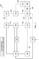
- Figure 1 is a simplified functional block diagram of an example embodiment of a therapy system 100 that can provide negative-pressure therapy with instillation of treatment solutions in accordance with this specification.
- tissue site in this context broadly refers to a wound, defect, or other treatment target located on or within tissue, including, but not limited to, bone tissue, adipose tissue, muscle tissue, neural tissue, dermal tissue, vascular tissue, connective tissue, cartilage, tendons, or ligaments.
- a wound may include chronic, acute, traumatic, subacute, and dehisced wounds; partial-thickness burns; ulcers (such as diabetic, pressure, or venous insufficiency ulcers); flaps; and grafts, for example.
- tissue site may also refer to areas of any tissue that are not necessarily wounded or defective but are instead areas in which it may be desirable to add or promote the growth of additional tissue. For example, negative pressure may be applied to a tissue site to grow additional tissue that may be harvested and transplanted.
- the therapy system 100 may include or be configured to be coupled to one or more distribution components.
- a distribution component may refer to any complementary or ancillary component configured to be fluidly coupled to a negative-pressure supply between a negative-pressure supply and a tissue site.
- a distribution component is preferably detachable and may be disposable, reusable, or recyclable.
- a dressing 102 is illustrative of a distribution component fluidly coupled to a negative-pressure source 104 in Figure 1 .
- a dressing may include a cover, a tissue interface, or both in some embodiments.
- the dressing 102 for example, may include a cover 106, a dressing interface 107, and a tissue interface 108.
- the cover 106 may be configured to cover the tissue interface 108 and the tissue site, and may be adapted to seal the tissue interface and create a therapeutic environment proximate to a tissue site for maintaining a negative pressure at the tissue site.
- the dressing interface 107 may be configured to fluidly couple the negative-pressure source 104 to the therapeutic environment of the dressing.
- the therapy system 100 may optionally include a fluid container, such as a container 112, coupled to the dressing 102 and to the negative-pressure source 104.
- the therapy system 100 may also include a source of instillation solution, such as a solution source 114.
- a distribution component may be fluidly coupled to a fluid path between a solution source and a tissue site in some embodiments.
- an instillation pump 116 may be coupled to the solution source 114, as illustrated in the example embodiment of Figure 1 .
- the instillation pump 116 may also be fluidly coupled to the negative-pressure source 104 such as, for example, by a fluid conductor 119.
- the instillation pump 116 may be directly coupled to the negative-pressure source 104, as illustrated in Figure 1 , but may be indirectly coupled to the negative-pressure source 104 through other distribution components in some embodiments.
- the instillation pump 116 may be fluidly coupled to the negative-pressure source 104 through the dressing 102.
- the instillation pump 116 and the negative-pressure source 104 may be fluidly coupled to two different locations on the tissue interface 108 by two different dressing interfaces.
- the negative-pressure source 104 may be fluidly coupled to the dressing interface 107 at a first location, while the instillation pump 116 may be fluidly to the coupled to dressing interface 107 at a second location as shown in Figure 1 .
- the therapy system 100 also may include sensors to measure operating parameters and provide feedback signals to the controller 110 indicative of the operating parameters.
- the therapy system 100 may include a first sensor 120 and/or a second sensor 124.
- the first sensor 120 may be configured to measure pressure in some examples.
- Other sensors, such as the second sensor 124 may be configured for measuring other properties in the therapy system 100 such as, for example, various pressures, voltages and currents.
- the first sensor 120 and the second sensor 124 may be electrically coupled to the controller 110 for providing information to the therapy system 100.
- the first sensor 120 may be fluidly coupled or configured to be fluidly coupled to a distribution component such as, for example, the negative-pressure source 104 either directly or indirectly through the container 112.
- the first sensor 120 may be configured to measure pressure in proximity to a tissue site, such as in the pressure in the dressing 102.
- the second sensor 124 may be in fluid communication with the output of the negative-pressure source 104 to directly measure the pump pressure (PP).
- the second sensor 124 may be electrically coupled to the negative-pressure source 104 to measure applied current as a proxy to the pump pressure.
- Distribution components may be fluidly coupled to each other to provide a distribution system for transferring fluids (i.e., liquid and/or gas).
- a distribution system may include various combinations of fluid conductors and fittings to facilitate fluid coupling.
- a fluid conductor generally includes any structure with one or more lumina adapted to convey a fluid between two ends, such as a tube, pipe, hose, or conduit.
- a fluid conductor is an elongated, cylindrical structure with some flexibility, but the geometry and rigidity may vary.
- Some fluid conductors may be molded into or otherwise integrally combined with other components.
- a fitting can be used to mechanically and fluidly couple components to each other.
- a fitting may comprise a projection and an aperture.
- the projection may be configured to be inserted into a fluid conductor so that the aperture aligns with a lumen of the fluid conductor.
- a valve is a type of fitting that can be used to control fluid flow. For example, a check valve can be used to substantially prevent return flow.
- a port is another example of a fitting.
- a port may also have a projection, which may be threaded, flared, tapered, barbed, or otherwise configured to provide a fluid seal when coupled to a component.
- distribution components may also be coupled by virtue of physical proximity, being integral to a single structure, or being formed from the same piece of material. Coupling may also include mechanical, thermal, electrical, or chemical coupling (such as a chemical bond) in some contexts.
- a tube may mechanically and fluidly couple the dressing 102 to the container 112 in some embodiments.
- components of the therapy system 100 may be coupled directly or indirectly.
- the negative-pressure source 104 may be directly coupled to the controller 110, and may be indirectly coupled to the dressing interface 107 through the container 112 by conduit 126 and conduit 128.
- the first sensor 120 may be fluidly coupled to the dressing 102 directly or indirectly by conduit 121 and conduit 122.
- the instillation pump 116 may be coupled indirectly to the dressing interface 107 through the solution source 114 and the instillation regulator 115 by fluid conductors 132, 134 and 138.
- the instillation pump 116 may be coupled indirectly to the second dressing interface 117 through the solution source 114 and the instillation regulator 115 by fluid conductors 132, 134 and 139.
- the fluid mechanics of using a negative-pressure source to reduce pressure in another component or location, such as within a sealed therapeutic environment, can be mathematically complex.
- the basic principles of fluid mechanics applicable to negative-pressure therapy and instillation are generally well-known to those skilled in the art, and the process of reducing pressure may be described illustratively herein as "delivering,” “distributing,” or “generating” negative pressure, for example.
- exudates and other fluids flow toward lower pressure along a fluid path.
- downstream typically implies something in a fluid path relatively closer to a source of negative pressure or further away from a source of positive pressure.
- upstream implies something relatively further away from a source of negative pressure or closer to a source of positive pressure.
- fluid inlet or “outlet” in such a frame of reference. This orientation is generally presumed for purposes of describing various features and components herein.
- the fluid path may also be reversed in some applications (such as by substituting a positive-pressure source for a negative-pressure source) and this descriptive convention should not be construed as a limiting convention.
- Negative pressure generally refers to a pressure less than a local ambient pressure, such as the ambient pressure in a local environment external to a sealed therapeutic environment provided by the dressing 102.
- the local ambient pressure may also be the atmospheric pressure at which a tissue site is located.
- the pressure may be less than a hydrostatic pressure associated with tissue at the tissue site.
- values of pressure stated herein are gauge pressures.
- references to increases in negative pressure typically refer to a decrease in absolute pressure, while decreases in negative pressure typically refer to an increase in absolute pressure.
- the pressure is generally a low vacuum, also commonly referred to as a rough vacuum, between -5 mm Hg (-667 Pa) and -500 mm Hg (-66.7 kPa).
- a rough vacuum between -5 mm Hg (-667 Pa) and -500 mm Hg (-66.7 kPa).
- Common therapeutic ranges are between -75 mm Hg (-9.9 kPa) and -300 mm Hg (-39.9 kPa).
- a negative-pressure supply such as the negative-pressure source 104, may be a reservoir of air at a negative pressure, or may be a manual or electrically-powered device that can reduce the pressure in a sealed volume, such as a vacuum pump, a suction pump, a wall suction port available at many healthcare facilities, or a micro-pump, for example.
- a negative-pressure supply may also have one or more supply ports configured to facilitate coupling and de-coupling the negative-pressure supply to one or more distribution components.
- the tissue interface 108 can be generally adapted to contact a tissue site.
- the tissue interface 108 may be partially or fully in contact with the tissue site. If the tissue site is a wound, for example, the tissue interface 108 may partially or completely fill the wound, or may be placed over the wound.
- the tissue interface 108 may take many forms, and may have many sizes, shapes, or thicknesses depending on a variety of factors, such as the type of treatment being implemented or the nature and size of a tissue site. For example, the size and shape of the tissue interface 108 may be adapted to the contours of deep and irregular shaped tissue sites. Moreover, any or all of the surfaces of the tissue interface 108 may have projections or an uneven, coarse, or jagged profile that can induce strains and stresses on a tissue site, which can promote granulation at the tissue site.
- the tissue interface 108 may comprise or consist essentially of a manifold.
- a "manifold" in this context generally includes any substance or structure providing a plurality of pathways adapted to collect or distribute fluid across a tissue site under pressure.
- a manifold may be adapted to receive negative pressure from a source and distribute negative pressure through multiple apertures across a tissue site, which may have the effect of collecting fluid from across a tissue site and drawing the fluid toward the source.
- the fluid path may be reversed or a secondary fluid path may be provided to facilitate delivering fluid across a tissue site.
- a manifold may be a porous foam material having interconnected cells or pores.
- cellular foam, open-cell foam, reticulated foam, porous tissue collections, and other porous material such as gauze or felted mat generally include pores, edges, and/or walls adapted to form interconnected fluid channels.
- Liquids, gels, and other foams may also include or be cured to include apertures and fluid pathways.
- a manifold may additionally or alternatively comprise projections that form interconnected fluid pathways.
- a manifold may be molded to provide surface projections that define interconnected fluid pathways.
- the average pore size of a foam manifold may vary according to needs of a prescribed therapy.
- the tissue interface 108 may be a foam manifold having pore sizes in a range of 400-600 microns.
- the tensile strength of the tissue interface 108 may also vary according to needs of a prescribed therapy. For example, the tensile strength of a foam may be increased for instillation of topical treatment solutions.
- the tissue interface 108 may be reticulated polyurethane foam such as found in GRANUFOAM TM dressing or V.A.C. VERAFLO TM dressing, both available from Kinetic Concepts, Inc. of San Antonio, Texas.
- the tissue interface 108 may be either hydrophobic or hydrophilic.
- the tissue interface 108 may also wick fluid away from a tissue site, while continuing to distribute negative pressure to the tissue site.
- the wicking properties of the tissue interface 108 may draw fluid away from a tissue site by capillary flow or other wicking mechanisms.
- An example of a hydrophilic foam is a polyvinyl alcohol, open-cell foam such as V.A.C. WHITEFOAM TM dressing available from Kinetic Concepts, Inc. of San Antonio, Texas.
- Other hydrophilic foams may include those made from polyether.
- Other foams that may exhibit hydrophilic characteristics include hydrophobic foams that have been treated or coated to provide hydrophilicity.
- the tissue interface 108 may further promote granulation at a tissue site when pressure within the sealed therapeutic environment is reduced.
- any or all of the surfaces of the tissue interface 108 may have an uneven, coarse, or jagged profile that can induce microstrains and stresses at a tissue site if negative pressure is applied through the tissue interface 108.
- the tissue interface 108 may be constructed from bioresorbable materials. Suitable bioresorbable materials may include, without limitation, a polymeric blend of polylactic acid (PLA) and polyglycolic acid (PGA). The polymeric blend may also include, without limitation, polycarbonates, polyfumarates, and capralactones.
- the tissue interface 108 may further serve as a scaffold for new cell-growth, or a scaffold material may be used in conjunction with the tissue interface 108 to promote cell-growth.
- a scaffold is generally a substance or structure used to enhance or promote the growth of cells or formation of tissue, such as a three-dimensional porous structure that provides a template for cell growth.
- Illustrative examples of scaffold materials include calcium phosphate, collagen, PLA/PGA, coral hydroxy apatites, carbonates, or processed allograft materials.
- the cover 106 may provide a bacterial barrier and protection from physical trauma.
- the cover 106 may also be constructed from a material that can reduce evaporative losses and provide a fluid seal between two components or two environments, such as between a therapeutic environment and a local external environment.
- the cover 106 may comprise or consist essentially of, for example, an elastomeric film or membrane that can provide a seal adequate to maintain a negative pressure at a tissue site for a given negative-pressure source.
- the cover 106 may have a high moisture-vapor transmission rate (MVTR) in some applications.
- MVTR moisture-vapor transmission rate
- the MVTR may be at least 250 grams per square meter per twenty-four hours in some embodiments, measured using an upright cup technique according to ASTM E96/E96M Upright Cup Method at 38°C and 10% relative humidity (RH). In some embodiments, an MVTR up to 5,000 grams per square meter per twenty-four hours may provide effective breathability and mechanical properties.
- the cover 106 may be a polymer drape, such as a polyurethane film, that is permeable to water vapor but impermeable to liquid.
- a polymer drape such as a polyurethane film
- Such drapes typically have a thickness in the range of 25-50 microns.
- the permeability generally should be low enough that a desired negative pressure may be maintained.
- the cover 106 may comprise, for example, one or more of the following materials: polyurethane (PU), such as hydrophilic polyurethane; cellulosics; hydrophilic polyamides; polyvinyl alcohol; polyvinyl pyrrolidone; hydrophilic acrylics; silicones, such as hydrophilic silicone elastomers; natural rubbers; polyisoprene; styrene butadiene rubber; chloroprene rubber; polybutadiene; nitrile rubber; butyl rubber; ethylene propylene rubber; ethylene propylene diene monomer; chlorosulfonated polyethylene; polysulfide rubber; ethylene vinyl acetate (EVA); co-polyester; and polyether block polymide copolymers.
- PU polyurethane
- PU polyurethane
- hydrophilic polyurethane such as hydrophilic polyurethane
- cellulosics such as cellulosics; hydrophilic polyamides
- the cover 106 may comprise INSPIRE 2301 having an MVTR (upright cup technique) of 2600 g/m 2 /24 hours and a thickness of about 30 microns.
- MVTR upright cup technique
- An attachment device may be used to attach the cover 106 to an attachment surface, such as undamaged epidermis, a gasket, or another cover.
- the attachment device may take many forms.
- an attachment device may be a medically-acceptable, pressure-sensitive adhesive that extends about a periphery, a portion, or an entire sealing member.
- some or all of the cover 106 may be coated with an acrylic adhesive having a coating weight between 25-65 grams per square meter (g.s.m.). Thicker adhesives or combinations of adhesives may be applied in some embodiments to improve the seal and reduce leaks.
- Other example embodiments of an attachment device may include a double-sided tape, paste, hydrocolloid, hydrogel, silicone gel, or organogel.
- a dressing interface may facilitate coupling the negative-pressure source 104 to the dressing 102.
- the negative pressure provided by the negative-pressure source 104 may be delivered through the conduit 128 to a negative-pressure connector that, in some embodiments, may include an elbow connector (not shown) having a first end adapted to be positioned in fluid communication with the tissue interface 108 and a second end extending at a substantially right angle from the first end adapted to be fluidly coupled to the conduit 128.
- the elbow connector may be substantially rigid.
- the negative-pressure interface may be semi-rigid such as, for example, a T.R.A.C.° Pad or Sensa T.R.A.C.° Pad available from KCI of San Antonio, Texas. The negative-pressure interface delivers negative pressure within an interior portion of the cover 106 and the tissue interface 108.
- a controller such as the controller 110, may be a microprocessor or computer programmed to operate one or more components of the therapy system 100, such as the negative-pressure source 104.
- the controller 110 may be a microcontroller, which generally comprises an integrated circuit containing a processor core and a memory programmed to control one or more operating parameters of the therapy system 100. Operating parameters may include, for example, the power applied to the negative-pressure source 104, the pressure generated by the negative-pressure source 104, or the pressure distributed to the tissue interface 108.
- the controller 110 is also preferably configured to receive one or more input signals and programmed to modify one or more operating parameters based on the input signals.
- Sensors such as the first sensor 120 or the second sensor 124, are generally known in the art as any apparatus operable to detect or measure a physical phenomenon or property, and generally provide a signal indicative of the phenomenon or property that is detected or measured.
- the first sensor 120 and the second sensor 124 may be configured to measure one or more operating parameters of the therapy system 100.
- the first sensor 120 may be a transducer configured to measure pressure in a pneumatic pathway and convert the measurement to a signal indicative of the pressure measured.
- the first sensor 120 may be a piezoresistive strain gauge.
- the second sensor 124 may optionally be configured to measure operating parameters of the negative-pressure source 104, such as the voltage or current, in some embodiments.
- the signals from the first sensor 120 and the second sensor 124 are suitable as an input signal to the controller 110, but some signal conditioning may be appropriate in some embodiments.
- the signal may need to be filtered or amplified before it can be processed by the controller 110.
- the signal is an electrical signal that is transmitted and/or received on by wire or wireless means, but may be represented in other forms, such as an optical signal.
- the solution source 114 is representative of a container, canister, pouch, bag, or other storage component, which can provide a solution for instillation therapy. Compositions of solutions may vary according to a prescribed therapy. Examples of therapeutic solutions that may be suitable for some prescriptions include hypochlorite-based solutions, silver nitrate (0.5%), sulfur-based solutions, biguanides, cationic solutions, and isotonic solutions.
- the solution source 114 may include a storage component for the solution and a separate cassette for holding the storage component and delivering the solution to the tissue site 150, such as a V.A.C. VeraLink TM Cassette available from Kinetic Concepts, Inc. of San Antonio, Texas.
- the container 112 may also be representative of a container, canister, pouch, or other storage component, which can be used to collect and manage exudates and other fluids withdrawn from a tissue site.
- a rigid container may be preferred or required for collecting, storing, and disposing of fluids.
- fluids may be properly disposed of without rigid container storage, and a re-usable container could reduce waste and costs associated with negative-pressure therapy.
- the container 112 may comprise a canister having a collection chamber, a first inlet fluidly coupled to the collection chamber and a first outlet fluidly coupled to the collection chamber and adapted to receive negative pressure from a source of negative pressure.
- a first fluid conductor may comprise a first member such as, for example, the conduit 128 fluidly coupled between the first inlet and the tissue interface 108 by the negative-pressure interface, and a second member such as, for example, the conduit 126 fluidly coupled between the first outlet and a source of negative pressure whereby the first conductor is adapted to provide negative pressure within the collection chamber to the tissue site.
- the therapy system 100 may also comprise a flow regulator such as, for example, a regulator 118 fluidly coupled to a source of ambient air to provide a controlled or managed flow of ambient air to the sealed therapeutic environment provided by the dressing 102 and ultimately the tissue site.
- a flow regulator such as, for example, a regulator 118 fluidly coupled to a source of ambient air to provide a controlled or managed flow of ambient air to the sealed therapeutic environment provided by the dressing 102 and ultimately the tissue site.
- the regulator 118 may control the flow of ambient fluid to purge fluids and exudates from the sealed therapeutic environment.
- the regulator 118 may be fluidly coupled to the tissue interface 108 through the dressing interface 107.
- the regulator 118 may be configured to fluidly couple the tissue interface 108 to a source of ambient air.
- the regulator 118 may be disposed within the therapy system 100 rather than being proximate to the dressing 102 so that the air flowing through the regulator 118 is less susceptible to accidental blockage during use. In such embodiments, the regulator 118 may be positioned proximate the container 112 and/or proximate a source of ambient air, where the regulator 118 is less likely to be blocked during usage.
- FIG. 2 is a schematic diagram of an example embodiment of the therapy system 100 configured to apply negative pressure and treatment solutions to a tissue site 150.
- Some components of the therapy system 100 may be housed within or used in conjunction with other components, such as processing units, alarm indicators, memory, databases, software, display devices, or user interfaces that further facilitate therapy.
- the negative-pressure source 104 may be combined with the controller 110 and other components into a therapy unit, such as a therapy unit 201 illustrated in Figure 2 .
- the therapy unit 201 may be, for example, a V.A.C.ULTA TM Therapy Unit available from Kinetic Concepts, Inc. of San Antonio, Texas.
- the tissue interface 108 may be placed within, over, on, or otherwise proximate a tissue site, such as tissue site 150.
- the cover 106 may be placed over the tissue interface 108 and an attachment device 202 can seal the cover 106 to an attachment surface near the tissue site 150.
- the cover 106 may be sealed to undamaged epidermis peripheral to a tissue site.
- the dressing 102 can provide a sealed therapeutic environment proximate to a tissue site, substantially isolated from the external environment, and the negative-pressure source 104 can reduce the pressure in the sealed therapeutic environment. Negative pressure applied across the tissue site 150 through the tissue interface 108 in the sealed therapeutic environment can induce macrostrain and microstrain in the tissue site, as well as remove exudates and other fluids from the tissue site, which can be collected in container 112.
- the therapy system 100 is presented in the context of a tissue site that includes a wound 152, which is through the epidermis 154, or generally skin, and the dermis 156 and reaching into a hypodermis, or subcutaneous tissue 158.
- the therapy system 100 may be used to treat a wound of any depth, as well as many different types of wounds, including open wounds, incisions, or other tissue sites.
- Treatment of the tissue site 150 may include removal of fluids originating from the tissue site 150, such as exudates or ascites, or fluids instilled into the dressing to cleanse or treat the tissue site 150, such as antimicrobial solutions.
- the dressing interface 107 of Figure 2 is substantially flat and flexible, but also compressible without occluding or blocking the fluid pathway between the conduit 128 and the tissue interface 108.
- the dressing interface 107 may comprise an applicator 208 adapted to be positioned in fluid communication with the tissue interface 108.
- a bridge 209 can be fluidly coupled to the applicator 208 and extend to an adapter 210.
- the bridge 209 may have a substantially flat profile, and the adapter 210 may be configured to fluidly couple the bridge 209 to a tube or other round fluid conductor, such as the conduit 128 illustrated in the example of Figure 2 .
- the adapter 210 may have one or more sealing valves, which can isolate the conduit 128 if separated from the dressing interface 107.
- the dressing interface 107 including both the applicator 208 and the bridge 209, may have a length that can vary between about 15 cm to about 30 cm.
- the applicator 208 and the bridge 209 may be formed as a single device as shown. In other embodiments, the applicator 208 and the bridge 209 may be separate components that are coupled together to form a single device. In yet other embodiments, the applicator 208 and the bridge 209 may be separate components that may be used independently of each other as a single component in the therapy system 100.
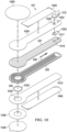
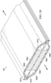
- Figure 3 is a segmented perspective bottom view of an example of the dressing interface 107, illustrating additional details that may be associated with some embodiments.
- the dressing interface 107 of Figure 3 generally has a low profile structure.
- Figure 3 further illustrates features that may be associated with some embodiments of the applicator 208 and the bridge 209 of Figure 2 .
- the applicator 208 may be bulbous or any shape suitable for applying therapy to the tissue interface 108, depending on the size and nature of the tissue site 150.
- the bridge 209 in the example of Figure 3 is generally long and narrow.
- An adapter such as the adapter 210, may fluidly couple the bridge 209 to a fluid conductor, such as the conduit 128.
- the conduit 128 and the conduit 122 may be combined in a conduit 310, as illustrated in the example of Figure 3 .
- the conduit 310 may be a multi-lumen tube in which a central lumen corresponds to the conduit 128 and one or more peripheral lumens corresponds to the conduit 122.
- the other end of the conduit 310 may be fluidly coupled to the negative-pressure source 104 and the first sensor 120 either directly or indirectly through the container 112.
- the applicator 208 and the bridge 209 may comprise a top layer such as, for example, a first layer 331, and a base layer such as, for example, a second layer 332.
- the second layer 332 is coupled to the first layer 331 around the periphery of the first layer 331 to form a sealed space within the dressing interface 107.
- the sealed space is formed between the first layer 331 and the second layer 332 of both the applicator 208 and the bridge 209.
- the first layer 331 and the second layer 332 are both formed from or include a polymeric film.
- the first layer 331 and the second layer 332 may be coupled around the periphery of the dressing interface 107 to form the sealed space by welding (RF or ultrasonic), heat sealing, or adhesive bonding such as, for example, acrylics or cured adhesives.
- the first layer 331 and the second layer 332 may be welded together around the periphery of the dressing interface 107 and may form a flange 339 around the periphery of the dressing interface 107 as a result of the weld.
- RF radio frequency
- the dressing interface 107 of Figure 3 may further comprise at least one barrier or wall, such as a first wall 335, between the first layer 331 and the second layer 332.
- the first wall 335 may extend from the end of the bridge 209 adjacent the adapter 210 into the applicator 208 to form at least two sealed spaces or fluid pathways between the first layer 331 and the second layer 332 within the dressing interface 107.
- the dressing interface 107 may further comprise a second barrier, such as a second wall 337, between the first layer 331 and the second layer 332.
- the second wall 337 also may extend from the end of the bridge 209 adjacent the adapter 210 into the applicator 208.
- the wall 335 and the wall 337 may comprise a polymeric film coupled between the first layer 331 and the second layer 332.
- the wall 335 and the wall 337 may comprise a weld (RF or ultrasonic), a heat seal, an adhesive bond, or a combination of any of the foregoing.
- RF or ultrasonic RF or ultrasonic
- a heat seal a heat seal
- an adhesive bond or a combination of any of the foregoing.
- such embodiments may form three sealed spaces or fluid pathways within the sealed space between the first layer 331 and the second layer 332.
- two of the fluid pathways may be dedicated to measuring pressure.
- a first pressure-sensing pathway 334 and a second pressure-sensing pathway 338 may be configured as feedback pathways.
- a third fluid pathway, such as a negative-pressure pathway 336, may be utilized for providing negative pressure.
- the first pressure-sensing pathway 334, the negative-pressure pathway 336, and the second pressure-sensing pathway 338 may be fluidly coupled to the conduit 310 by the adapter 210.
- the negative-pressure pathway 336 may be fluidly coupled to the conduit 128 so that the negative-pressure pathway 336 functions to deliver negative pressure to the tissue interface 108.
- the first pressure-sensing pathway 334 and the second pressure-sensing pathway 338 may be fluidly coupled to the conduit 122.
- the first pressure-sensing pathway 334 and the second pressure-sensing pathway 338 both may be fluidly coupled to a single space within the adapter 210 that is also fluidly coupled to the conduit 122.
- the other end of the first pressure-sensing pathway 334, the negative-pressure pathway 336, and the second pressure-sensing pathway 338 may terminate within the applicator 208 of the dressing interface 107 and be fluidly coupled to each other within the applicator 208 for delivering and sensing the negative pressure associated with the tissue interface 108.
- the applicator 208 may comprise an opening or aperture 342 in the second layer 332, adapted to fluidly couple the sealed space of the dressing interface 107 to the tissue interface 108.
- the aperture 342, along with the first layer 331 and the second layer 332 portions of the applicator 208 may define a recessed space 344 within the sealed space of the applicator 208, wherein the recessed space 344 is adapted to be in fluid communication with the tissue interface 108 in use.
- the portion of the recessed space 344 covered by the second layer 332 of the applicator 208 may be referred to as a covered space.
- the walls 335 and 337 may extend only partially into the recessed space 344 so that the end of the walls 335 and 337 are exposed by the aperture 342 as shown in Figure 3 .
- the first pressure-sensing pathways 334 and the second pressure-sensing pathway 338 are in fluid communication with the recessed space 344.
- the negative-pressure pathway 336 is also in fluid communication with the recessed space 344 and can be adapted to deliver negative pressure to the tissue interface 108 through the recessed space 344.
- the walls 335 and 337 may extend beyond the aperture 342 so that less of the first pressure-sensing pathway 334 and the second pressure-sensing pathway 338 are being exposed to negative pressure being delivered to the tissue interface 108 by the negative-pressure pathway 336 to avoid occlusions and/or blockages from the tissue site 150.
- the dressing interface 107 may further comprise a plurality of features, such as flexible projections, flexible standoffs, or closed cells.
- closed cells 340 illustrated in the example of Figure 3 may be generally characterized as bubbles that have a bottom portion extending from the first layer 331 and a top portion extending within the sealed spaces toward the second layer 332 outside the recessed space 344.
- the top portion of the closed cells 340 extending from the first layer 331 may extend toward the tissue interface 108 and may be adapted to come in direct contact with the tissue interface 108 in use.
- Features such as the closed cells 340 can provide a cushion to help prevent the sealed spaces of the dressing interface 107 from collapsing as a result of external forces.
- the top portion of the closed cells 340 may come in contact with the second layer 332, and in some other example embodiments, the top portion of the closed cells 340 may be coupled to the second layer 332.
- the closed cells 340 may be disposed in the applicator 208 but not in the bridge 209, which may contain, for example, a fabric material instead of the closed cells 340.
- the features may comprise projections or nodes (not shown) having a flexibility similar to the closed cells 340.
- the dressing interface 107 of Figure 3 may also comprise an affixation surface 346 surrounding the aperture 342 in the applicator 208 of the second layer 332 that can be used to couple the dressing interface 107 to a tissue site.
- the affixation surface 346 and the first layer 331 form a circumferential pathway 345 that may be an extension of the negative-pressure pathway 336.
- a top drape (not shown) may be utilized to cover the applicator 208 to provide additional protection and support over the applicator 208 when the dressing interface 107 is applied to a tissue site.
- a top drape may also be utilized to cover any adhesive that might be exposed from applying the dressing interface 107 to the tissue site.
- a top drape may be similar to the cover 106.
- a top drape may comprise or consist of a polymer, such as a polyurethane film.
- Figure 3A is a section view of the applicator 208 of Figure 3 , taken along line 3A-3A, illustrating additional details that may be associated with some embodiments.
- the top portion of the closed cells 340 may extend from the first layer 331 toward the tissue interface 108 through the aperture 342 of the second layer 332 as illustrated in Figure 3A .
- At least some of the closed cells 340 may be configured to come in direct contact with the tissue interface 108 through the aperture 342.
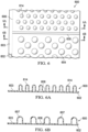
- Figure 3B is a section view of another example of the applicator 208, illustrating details that may be associated with some embodiments.
- the applicator 208 may further comprise a plurality of features or closed cells having a bottom portion extending from the second layer 332 and a top portion extending within the sealed spaces outside the recessed space 344 toward the first layer 331.
- the top portions of the closed cells 340 may still extend from the first layer 331 into the recessed space 344.
- Figure 3C is a section view of another example of the applicator 208.
- the applicator 208 comprises both a plurality of closed cells 340 and a plurality of closed cells 350 extending from the first layer 331 and the second layer 332, respectively, within the sealed spaces outside the recessed space 344 toward the second layer 332 and the first layer 331, respectively.
- the top portions of the closed cells 340 may extend from the first layer 331 into the recessed space 344.
- the first layer 331 and the second layer 332, including the closed cells 340 and the closed cells 350, respectively, may be formed from a non-porous, polymeric film that may comprise any flexible material that can be manipulated to enclose closed cells, including various thermoplastic materials, e.g., polyethylene homopolymer or copolymer, polypropylene homopolymer or copolymer, etc.
- thermoplastic polymers include polyethylene homopolymers, such as low density polyethylene (LDPE) and high density polyethylene (HDPE), and polyethylene copolymers such as, e.g., ionomers, EVA, EMA, heterogeneous (Zeigler-Natta catalyzed) ethylene/alpha-olefin copolymers, and homogeneous (metallocene, single-cite catalyzed) ethylene/alpha-olefin copolymers.
- LDPE low density polyethylene
- HDPE high density polyethylene
- polyethylene copolymers such as, e.g., ionomers, EVA, EMA, heterogeneous (Zeigler-Natta catalyzed) ethylene/alpha-olefin copolymers, and homogeneous (metallocene, single-cite catalyzed) ethylene/alpha-olefin copolymers.
- Ethylene/alpha-olefin copolymers are copolymers of ethylene with one or more comonomers selected from C 3 to C 20 alpha-olefins, such as 1-butene, 1-pentene, 1-hexene, 1-octene, methyl pentene and the like, in which the polymer molecules comprise long chains with relatively few side chain branches, including linear low density polyethylene (LLDPE), linear medium density polyethylene (LMDPE), very low density polyethylene (VLDPE), and ultra-low density polyethylene (ULDPE).
- LLDPE linear low density polyethylene
- LMDPE linear medium density polyethylene
- VLDPE very low density polyethylene
- ULDPE ultra-low density polyethylene
- polypropylene homopolymer or polypropylene copolymer e.g., propylene/ethylene copolymer
- polyesters e.g., polystyrenes, polyamides, polycarbonates, etc.
- the first layer 331 and the second layer 332, including the closed cells 340 and the closed cells 350, respectively, may comprise a polymeric film such as, for example, a thermoplastic polyurethane (TPU) film that is permeable to water vapor but impermeable to liquid.
- the first layer 331 and the second layer 332 may be in various degrees breathable and may have MVTRs which are proportional to their thickness.
- the MVTR may be at least 300 g/m 2 per twenty-four hours in some embodiments.
- the permeability generally should be low enough to maintain a desired negative pressure for the desired negative therapy treatment.
- the layer having the closed cells may be formed from two sheets of polymeric film having inner surfaces coupled together to form sealed regions defining the plurality of closed cells. If the dressing interface 107 is positioned at the tissue site and negative pressure is applied as described above, the closed cells formed by the polymeric film are structured so that they do not completely collapse from apposition forces resulting from the application of negative pressure and/or external forces to the dressing interface 107 and the tissue site.
- the two sheets of polymeric film may be a single sheet of material having two laminae or two separate sheets that are coupled together to form the closed cells.
- the sheets of polymeric film may initially be separate sheets that are brought into superposition and sealed or they may be formed by folding a single sheet unto itself with a heat-sealable surface facing inward.
- Each sheet of the polymeric film also may be a monolayer or multilayer structure, depending on the application or the desired structure of the closed cells.
- the polymeric film may possess sufficient tensile strength to resist stretching under apposition forces created by negative pressure therapy.
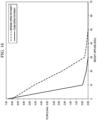
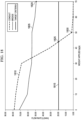
- the tensile strength of a material is the ability of material to resist stretching as represented by a stress-strain curve where stress is the force per unit area, i.e., pascals (Pa), newtons per square meter (N/m 2 ), or pounds per square inch (psi).
- the ultimate tensile strength (UTS) is the maximum stress the material can withstand while being stretched before failing or breaking.
- Many materials display a linear elastic behavior defined by a linear stress-strain relationship often extending up to a nonlinear region represented by the yield point, i.e., the yield strength of a material.
- high density polyethylene has a high tensile strength and low-density polyethylene (LDPE) has a slightly lower tensile strength, which are suitable materials for the sheets of non-porous, polymeric film as set forth above.
- Linear low density polyethylene (LLDPE) is often used as well because the material stretches very little as the force is increased up to the yield point of the material. Thus, the closed cells are able to resist collapsing (or stretching) when subjected to an external force or pressure.
- HDPE has a UTS of about 37 MPa and may have a yield strength that ranges from about 26-33 MPa depending on the thickness of the material, while LDPE has somewhat lower values.
- the first layer 331 and the second layer 332, including the closed cells 340 and the closed cells 350, respectively, may comprise a thermoplastic polyurethane (TPU) film as described above.
- the thermoplastic polyurethane film may be, for example, a Platilon@ thermoplastic polyurethane film available from Convestro LLC, which may have a UTS of about 60 MPa and may have a yield strength of approximately 11 MPa or greater than about 10 MPa depending on the thickness of the material. Therefore, in some example embodiments, it is desirable that the non-porous, polymeric film may have a yield strength greater than about 10 MPa, depending on the type and thickness of material. A material having a lower yield strength may be too stretchable and, therefore, more susceptible to breaking with the application of small amounts of compression and/or apposition forces.
- Figure 4 is a top view a layer 400 that may be illustrative of features that may be associated with various examples of the first layer 331, the second layer 332, or both.
- the layer 400 may comprise two sheets of polymeric film, such as a sheet 402 and a sheet 403.
- the sheet 403 may have a plurality of blisters 404 in some embodiments.
- the blisters 404 may comprise raised formations that extend above or below a plane of the sheet 403. Within each of the blisters 404 may be an empty cavity, which may be open to the surrounding environment.
- the blisters 404 may be vacuum-formed regions of the sheet 403.
- each of the sheet 402 and the sheet 403 may have inner surfaces coupled to each other to form a sealed region 406.
- the sheet 402 may also cover the blisters 404 to form a plurality of closed cells 407 in the remaining portion of the sheet 402 and the sheet 403.
- the sealed region 406 may be formed by a heat seal between the inner surfaces of the sheets 402 and 403, while the blisters 404 may be formed simultaneously by vacuum forming.
- the sealed region 406 may be formed by adhesion between the sheet 402 and the sheet 403.
- the sheet 402 and the sheet 403 may be adhesively bonded to each other.
- the sealed region 406 may be flexible enough so that the dressing interface 107 is sufficiently flexible to conform to the shape the tissue site.
- the sealed region 406 may be sufficiently flexible or sized so that the dressing interface 107 may be folded to conform to a tissue site to provide optimal negative pressure to the tissue site.
- the closed cells 407 may be substantially airtight to inhibit collapsing of the closed cells 407 from the application of negative pressure, which could block the flow of fluid through the dressing interface 107.
- the closed cells 407 may be substantially airtight when formed and have an internal pressure that is an ambient pressure.
- the closed cells 407 may be inflated with air or other suitable gases such as, for example, carbon dioxide or nitrogen.
- the closed cells 407 may be inflated to have an internal pressure greater than the atmospheric pressure to maintain their shape and resistance to collapsing under pressure and external forces.
- the closed cells 407 may be inflated to a pressure up to about 25 psi above the atmospheric pressure.
- the sheet 402 and the sheet 403 may have a thickness within a range of 400 to 600 microns.
- the first layer 331 and the second layer 332, including the closed cells 340 and the closed cells 350 respectively may be formed from thermoplastic polyurethane film having a thickness of about 500 microns.
- the sheet 402 and the sheet 403, prior to fabricating either one of the first layer 331 or the second layer 332, may each have a thickness of about 200 ⁇ m to about 600 ⁇ m.
- the sheet 402 and the sheet 403 may each have a thickness of about 250 ⁇ m.
- the sheet 402 and the sheet 403 may each have a thickness of about 500 ⁇ m.
- the thickness of a layer that does not have closed cells may be up to 50% thinner than the thickness of the layer that that includes closed cells.
- the thickness of the second layer 332 without any closed cells may be up to 50% thinner than the thickness of the first layer 331 that has the closed cells 340.
- the sealed region 406 may have a thickness between about 800 ⁇ m and about 1200 ⁇ m. If the fabrication process comprises injection molding, the blisters 404 may have a thickness between about 400 ⁇ m and about 500 ⁇ m. However, if the blisters 404 are fabricated by drawing the film, the top portion of the blisters 404 may have a thickness as thin as 50 ⁇ m.
- the walls of the blisters 404 may have a thickness relative to the thickness of the individual sheets 402 and 403 as defined by a draw ratio, i.e., the ratio of the average height of the blisters 404 to the average thickness of the sheets 402 and 403.
- the blisters 404 may have a generally tubular shape, which may have been formed from the sheets 402 and 403 having various thicknesses and draw ratios.
- the sheets 402 and 403 may have an average thickness of 500 ⁇ m and the blisters 404 may have an average height in a range between about 2.0 mm and 5.0 mm.
- the blisters 404 may have a draw ratio ranging from about 4:1 to about 10:1 for heights of 2.0 and 5.0 mm, respectively.
- the draw ratio may range from about 5:1 to about 13:1 where the thickness of the sheets 402 and 403 is an average of about 400 ⁇ m.
- the draw ratio may range from about 3:1 to about 9:1 where the thickness of the sheets 402 and 403 is an average of about 600 ⁇ m.
- the blisters 404 may have an average height in a range between about 1.0 mm and 4.0 mm, depending on the thickness of the sheets 402 and 403.
- the sheets 402 and 403 may each have the same or different thicknesses and flexibilities, but are substantially non-stretchable as described above so that the closed cells 407 maintain a generally constant volume without bursting after a compression force is applied to the dressing interface 107 or negative pressure is applied to the dressing interface 107 and the tissue site. Consequently, even when a load is applied to the dressing interface 107, which squeezes the closed cells 407 into a different shape, the closed cells 407 are sufficiently flexible to recover their original shape after being squeezed without bursting.
- the sealed region 406 may define the base or the cross-sectional shape of the closed cells 407 as being generally circular as shown, but in other embodiments may define the base as being a rectangular or triangular shape, hexagonal, or other geometric or an irregular shape.
- Figure 4A is a section view of the layer 400 taken along line 4A-4A of Figure 4 , illustrating additional details that may be associated with some examples.
- the blisters 404 may be hemispherical, as illustrated in the example of Figure 4A .
- the blisters 404 may be conical, cylindrical, tubular having a flattened or hemispherical end, or geodesic. These shapes may be formed in either one of the sheets 402 and 403, such as the tubular shape of the blisters 404 shown in Figure 4A .
- the blisters 404 may be tubular shapes formed with generally parallel walls extending from the sealed region 416 to a hemispherical or flat top portion of the blisters 404.
- the walls of the blisters 404 may taper or expand outwardly from the sealed region 416 to the top portion so that the diameter of the top portion of the closed cells 407 is larger than at the base of the closed cells 407.
- the blisters 404 that are generally hemispherical or tubular in shape may have a diameter between about 1.0 mm and about 10 mm. In some other embodiments, the blisters 404 may have a diameter between about 2.0 mm and about 5.0 mm. In some embodiments, the blisters 404 also may have a pitch, i.e., the center to center distance between each of the blisters 404, between about 1 mm and 10 mm. In some other embodiments, the blisters 404 may also have a pitch between about 2 mm and about 3 mm.
- the surface area of the layer 400 covered by the closed cells 407 may also be determined as a percentage, i.e., the cell coverage percentage.
- the cell coverage percentage is about 22% of the surface area of the layer 400.
- the cell coverage percentage is about 14% of the surface area of the layer 400.
- the cell coverage percentage is about 51% of the surface area of the layer 400.
- the cell coverage percentage may range between about 10% and about 60% of the surface area of either one of the layers having the closed cells such as layer 400. Blisters 404 having other shapes also may have a cell coverage percentage in generally the same range.
- a portion of the closed cells 340 may extend through the recessed space 344 and the aperture 342 of the dressing interface 107 to contact the tissue interface 108.
- a portion of the closed cells 340 extending through the recessed space 344 may be textured with surface features, which may be protrusions or indentations, to enhance fluid flow through the dressing interface 107 to the tissue interface 108 and the tissue site.
- Figure 4B is a section view of the layer 400 of Figure 4 taken along line 4B-4B, illustrating additional details that may be associated with some examples.
- one or more of the blisters 404 are embossed with projections or nodes, such as the nodes 419.
- the nodes 419 can be configured to contact the tissue interface 108 to enhance fluid flow to a tissue site.
- the nodes 419 may be projections that are flexible or rigid.
- the projections may be formed from a substantially gas impermeable material such as silicone.
- the projections may be formed from a semi-gas permeable material.
- the projections may be formed as an integral part of the sheet 403, and, therefore, they may also be formed from the same material.
- the projections may be solid, while in other embodiments the projections may be hollow to increase flexibility.
- the projections may form a plurality of channels and/or voids to distribute reduced pressure and allow for fluid flow among the projections.
- the projections may be dimensioned to provide local load points evenly distributed at the tissue interface 108.
- the pattern and position of the projections may be uniform or non-uniform.
- the projections may have different shapes, including, for example, the shape of a spike, cone, pyramid, dome, cylinder or rectangle.
- the blisters 404 in adjacent rows or columns may be staggered in some examples, so that the cells may be nested together.
- the blisters 404 may be arranged in other patterns suitable for the particular therapy being utilized.
- the rows and columns of the blisters 404 may be arranged in line to form an aligned, rectangular pattern so that there is more spacing between the blisters 404.
- Increasing the spacing between the blisters 404 may increase fluid flow within the fluid pathways of the dressing interface 107, whereas a nested arrangement of closed cells may restrict fluid flow within the fluid pathways.
- the closed cells 340 disposed in the negative-pressure pathway 336 are arranged in an aligned pattern that may increase fluid flow of negative pressure being applied to the tissue interface 108 to facilitate the removal of fluids and exudates within the recessed space 344.
- the closed cells 340 disposed in the pressure-sensing pathways 334 and 338 can be arranged in a nested pattern to facilitate pressure sensing within the recessed space 344 while impeding the inflow of fluids and exudates into the pressure-sensing pathways 334 and 338 to reduce the possibility of blockage.
- the size and pitch of the closed cells also may be varied to effect change in the fluid flows through the fluid passageways.
- the closed cells 340 disposed in the negative-pressure pathway 336 have a slightly larger diameter and pitch than the closed cells 340 disposed in the pressure-sensing pathways 334 and 338 that may increase fluid flow of negative pressure being applied to the tissue interface 108 to facilitate the removal of fluids and exudates within the recessed space 344.
- the closed cells 340 disposed in the pressure-sensing pathways 334 and 338 have a slightly smaller diameter and pitch that may restrict fluid flow to facilitate pressure sensing within the recessed space 344 while impeding the inflow of fluids and exudates into the sensing pathways 334 and 338 to avoid blockages.
- Figure 5 is a top view of another example layer, illustrating certain features that may additionally or alternatively be associated with various examples of the first layer 331, the second layer 332, or both.
- a layer 500 may comprise chambers formed between closed cells to better distribute the apposition force applied to the layer 500 as a result of the application of negative pressure, because the volume of the chambers is greater than the volume of the individual closed cells.
- the layer 500 may be similar in many respects to the layer 400, comprising two sheets 502 and 503 of polymeric film.
- the sheet 503 may have a plurality of blisters 504.
- the sheet 502 and the sheet 503 may have inner surfaces coupled to each other in a pattern defining a plurality of closed cells 507.
- the sheets 502 and 503 may be sealed to each other to form a sealed region 506 defining the closed cells 507.
- the layer 500 also may comprise a plurality of passageways 508 fluidly coupling at least two of the closed cells 507 to form a closed chamber.
- a closed chamber may be formed by all of the closed cells 507 in a row fluidly coupled by the passageways 508 as shown in Figure 5 .
- the closed chambers may be formed in alternating rows as also shown in Figure 5 . The formation of closed chambers with closed cells in any pattern distributes apposition forces applied to the layer 500 more equally across the layer 500.
- Figure 5A is a section view of the layer 500 taken along line 5A-5A, illustrating additional details that may be associated with some embodiments.
- the closed cells 507 may be fluidly coupled through the passageways 508.
- Figure 5B is a section view of the layer 500 taken along line 5B-5B, illustrating additional details that may be associated with some embodiments.
- one or more of the blisters 504 may be textured with surface features, which may be protrusions or indentations, to enhance fluid flow through the dressing interface 107.
- one or more of the blisters 504 may be embossed with projections or nodes, such as the nodes 519, which can contact the tissue interface 108 to enhance fluid flow to a tissue site.
- a closed-cell layer 600 also comprises two sheets 602 and 603 of polymeric film having inner surfaces sealed to each other in a pattern defining a plurality of closed cells in a nested arrangement including closed cells 607 and smaller closed cells 614.
- the sheets 602 and 603 may be sealed to each other to form a sealed region 606 defining the closed cells 607 and 614.
- a wall 635 similar to the first wall 335 shown in Figure 3 may be disposed between the plurality of closed cells 607 and 614 forming the negative-pressure pathway 336 and the pressure-sensing pathway 334, respectively.
- the closed cells 607 disposed in the negative-pressure pathway 336 have a noticeably larger diameter and pitch than the smaller closed cells 614 that may increase fluid flow of negative pressure being applied to the tissue interface 108 to facilitate the removal of fluids and exudates within the recessed space 344.
- the larger closed cells 607 may have a diameter in the range between about 1 mm and about 10 mm, whereas the smaller closed cells 614 may have a diameter in the range between about 1 mm and about 3 mm.
- the closed cells 614 disposed in the pressure-sensing pathway 334 have a noticeably smaller diameter and pitch than the larger closed cells 607 that may restrict fluid flow to facilitate pressure sensing within the recessed space 344 while impeding the inflow of fluids and exudates into the pressure-sensing pathway 334. It should be understood that the arrangement and dimensions of the closed cells may be tailored to manage the delivery of negative pressure to the tissue interface 108 and the measurement of pressure within the recessed space 344.
- the tissue interface 108 may be placed within, over, on, or otherwise proximate a tissue site, such as the tissue site 150, as shown in the example of Figure 2 .
- the cover 106 may be placed over the tissue interface 108 and sealed to an attachment surface near the tissue site 150.
- the cover 106 may be sealed to undamaged epidermis peripheral to a tissue site.
- the dressing 102 can provide a sealed therapeutic environment proximate to a tissue site, substantially isolated from the external environment, and the negative-pressure source 104 can reduce the pressure in the sealed therapeutic environment.
- FIG 7 is a schematic diagram of the dressing interface 107 of Figure 3 applied to the tissue site 150.
- the tissue interface 108 may be in fluid communication with the recessed space 344 through the aperture 342 of the dressing interface 107.
- the affixation surface 346 of the dressing interface 107 may be coupled to the cover 106 to seal and fluidly couple the recessed space 344 of the dressing interface 107 to the tissue interface 108.
- the affixation surface 346 and the first layer 331 form the circumferential pathway 345 that may be an extension of the negative-pressure pathway 336.
- the first wall 335 and the second wall 337 form the three sealed spaces or fluid pathways 334, 336 and 338 (as indicated by the dashed line arrows in Figure 3 ) between the first layer 331 and the second layer 332 as described above.
- the top portion of the closed cells 340 can extend from the first layer 331 toward the tissue interface and may be adapted to come in direct contact with the tissue interface 108 if negative pressure is applied to the dressing interface 107. If negative pressure is applied to the tissue interface 108, the dressing interface 107 can be compressed as a result of an apposition force that causes the first layer 331 and the second layer 332 to collapse toward each other because of the vacuum created within the spaces between the closed cells 340.
- the closed cells 340 may change shape or flatten somewhat during the application of negative pressure to the tissue interface 108, the volume of the closed cells 340 remains substantially constant and, as a result, maintains fluid flow through the negative-pressure pathway 336 to continue providing negative pressure therapy to the tissue site 150 and measuring the pressure provided by the pressure-sensing pathways 334 and 338.
- the closed cells 340 also provide a cushion to help prevent the sealed spaces of the dressing interface 107 from collapsing as a result of external forces as described above.
- the closed cells 340 disposed in the negative-pressure pathway 336 may be sized and arranged in a pattern that may increase fluid flow of negative pressure being applied to the tissue interface 108 to facilitate the removal of fluids and exudates within the recessed space 344.
- the closed cells 340 disposed in the pressure-sensing pathways 334 and 338 may be sized and arranged in a pattern to facilitate pressure sensing within the recessed space 344 while impeding the inflow of fluids and exudates into the sensing pathways 334 and 338 to reduce the possibility of blockages.
- the closed cells 340 of the dressing interface 107 may have a variety of shapes, and may be sized and arranged in different patterns within the sealed space to enhance the delivery of negative pressure to the tissue interface 108 for a specific type of tissue site while optimizing pressure sensing and measurement of the negative pressure within the recessed space 344.
- Another example of the dressing interface 107 is shown in Figures 8A, 8B , and 9 .
- Figures 8A and 8B are segmented perspective views of the bottom and top of the dressing interface 107 having a low-profile structure that may be associated with some example embodiments of the therapy system of Figure 1 .
- Figure 9 is a perspective bottom view of the dressing interface 107 having a low-profile structure that may be associated with some example embodiments of the therapy system of Figure 1 including both the bottom view shown in Figure 8A and top view shown in Figure 8B .
- the applicator 208 of Figure 8A has a circular shape.
- the adapter 312 of Figure 8B may be functionally the same as the adapter 210 of Figure 3 , but has a different structure that may include a semi-rigid elbow connector having a low-profile configuration.
- the aperture 342 in the second layer 332 may have a generally circular shape that opens to the recessed space 344.
- the closed cells 340 may have a generally elongated and convex shape and may be arranged in a generally circular pattern disposed within the recessed space 344.
- the closed cells 340 may also comprise surface features, similar to the nodes 419.
- the closed cells 340 disposed in the center of the recessed space 344 may be more aligned with the negative-pressure pathway 336 to increase fluid flow of negative pressure being applied to the tissue interface 108 to facilitate the removal of fluids and exudates within the recessed space 344.
- some of the closed cells 340 may be disposed around the aperture 342 to form a semicircular path opposite the negative-pressure pathway 336 including spaces or gaps 802 between the closed cells 340.
- the semicircular alignment of the closed cells 340 are positioned within the recessed space 344 to better avoid the flow of fluids passing through from the tissue interface 108 to the negative-pressure pathway 336 when negative pressure is applied.
- the gaps 802 are sufficiently small for further restricting fluid flow into the pressure-sensing pathways 334 and 338 as indicated by the dashed arrows.
- the gaps 802 facilitate pressure sensing within the recessed space 344 while impeding the inflow of fluids and exudates into the sensing pathways 334 and 338 to reduce the possibility of blockage.
- a portion of the aperture perimeter may be welded to the outer circle of the closed cells 340 to further restrict fluid flow to the pressure-sensing pathways 334 and 338 in order to further impede the inflow of fluids and exudates without inhibiting pressure sensing within the recessed space 344.
- the closed cells 340 of the dressing interface 107 may have a variety of shapes, and may be sized and arranged in different patterns within the sealed space to enhance the delivery of negative pressure to the tissue interface 108 for a specific type of tissue site while optimizing pressure sensing and measurement of the negative pressure within the recessed space 344.
- Figure 10 is a perspective assembly view of another example of the dressing interface 107 having a low-profile structure that may be associated with some example embodiments of the therapy system of Figure 1 .
- the first layer 331 and the second layer 332 of the dressing interface 107 may be covered with a top film coat 1005 and a base film coat 1010, respectively, which may be sealed around their perimeter by a weld to enclose the first layer 331 and the second layer 332.
- the first layer 331 and the top film coat 1005 may each have ports 1015 and 1020, respectively, through which fluids from the negative-pressure pathway 336 may flow through the adapter 312 to the conduit 310.
- the first layer 331 and the top film coat 1005 may additionally have ports 1017 and 1022, respectively, which may be fluidly coupled to the conduit 122 through the adapter 312.
- the dressing interface 107 may further comprise a fluid exit bond 1025 which may be, for example, a weld between the first layer 331 and the top film coat 1005 to seal their respective ports 1015 and 1020 to prevent leakage of fluids flowing through the ports 1015 and 1020.
- the base film coat 1010 may have a port 1030 concentric with the aperture 342 of the second layer 332.
- the dressing interface 107 may further comprise a fluid exit bond 1035 which may be, for example, a weld between the second layer 332 and the base film coat 1010 to seal the aperture 342 and the port 1030 to prevent leakage of fluids flowing through them from the tissue interface 108 into the recessed space 344.
- the other side of the base film coat 1010 may include an attachment device such as, for example, attachment device 1038 that may be protected by a release layer 1039 prior to being applied to the tissue site.
- a top drape 1050 may be utilized to cover the applicator 208 to provide additional protection and support over the applicator 208 if the dressing interface 107 is applied to a tissue site.
- the top drape 1050 may also be utilized to cover any adhesive that might be exposed from applying the dressing interface 107 to a tissue site.
- the top drape 1050 may be similar to the cover 106.
- the top drape 1050 may be a polymer such as a polyurethane film.
- a first offloading layer 1040 may be disposed on the base film coat 1010 and, in some embodiments, a second offloading layer 1045 may be disposed on top film coat 1005.
- the first offloading layer 1040 and the second offloading layer 1045 may have edges sealed together to encapsulate the dressing interface 107.
- the first offloading layer 1040 and the second offloading layer 1045 may be a single sleeve that slides over the dressing interface 107.
- the first layer 331 and the second layer 332 form the negative-pressure pathway 336, a single fluid conductor, through which fluids may flow from the aperture 342 and exiting the adapter 312.
- the first offloading layer 1040 and the second offloading layer 1045 may facilitate the distribution of pressure at the tissue site to reduce to prevent further breakdown of the fragile periwound skin.
- the first offloading layer 1040 and the second offloading layer 1045 may comprise a variety of materials and configurations that are suitable for offloading pressure being applied by the negative-pressure pathway 336 of the dressing interface 107 against the tissue site, especially when fluids flow through the negative-pressure pathway 336.
- the first offloading layer 1040 and the second offloading layer 1045 may be polyurethane (PU) foam.
- the first offloading layer 1040 and the second offloading layer 1045 may be polyurethane (PU) foam that is hydrophilic.
- materials suitable for some embodiments of the first offloading layer 1040 and the second offloading layer 1045 may include polyurethane foam available from AMS (Advanced Medical Systems) such as, for example, their MCF03 polyurethane foam, or polyurethane hydrophilic foam available from Freudenberg such as, for example, their hydrophilic polyurethane foam PU Foam-1034.
- the thickness of the first offloading layer 1040 and the second offloading layer 1045 is in a range of about 2 millimeters to about 8 millimeters and, preferably, in a range of about 3 millimeters to about 5 millimeters.
- Figures 11A and 11B are segmented perspective bottom and top views, respectively, of the applicator 208 and the adapter 312 of the dressing interface 107 of Figure 10 .
- the dressing interface 107 may further comprise at least one barrier or wall such as, for example, a first wall 1105, coupled between the first layer 331 and the second layer 332.
- the first wall 1105 may extend from the end of the bridge 209 adjacent the adapter 312 into the applicator 208 to form at least two sealed spaces or fluid pathways between the first layer 331 and the second layer 332 within the dressing interface 107.
- the dressing interface 107 may further comprise a second barrier such as, for example, a second wall 1110, coupled between the first layer 331 and the second layer 332.
- the second wall 1110 also may extend from the end of the bridge 209 adjacent the adapter 312 into the applicator 208.
- the first wall 1105 and the second wall 1110 may comprise a polymeric film coupled between the first layer 331 and the second layer 332.
- the first wall 1105 and the second wall 1110 may comprise a weld (RF or ultrasonic), a heat seal, an adhesive bond, or a combination of any of the foregoing.
- RF or ultrasonic RF or ultrasonic
- a heat seal e.g., a heat seal
- an adhesive bond a combination of any of the foregoing.
- such embodiments may form three sealed spaces or fluid pathways within the sealed space between the first layer 331 and the second layer 332.
- the first wall 1105 and the second wall 1110 cooperate with the flange 339 to form fluid conductors 1115 and 1120 for two of the fluid pathways that may be dedicated to measuring pressure such as, for example, pressure-sensing pathways 334 and 338 (as indicated by the dashed line arrows), leaving one of the fluid pathways to be utilized for providing negative pressure such as, for example, negative-pressure pathway 336 (as indicated by the dashed line arrows).
- the fluid conductors 1115 and 1120 may have a height having a value in a range between about 0.25 mm and about 3 mm.
- the fluid conductors 1115 and 1120 may have a width having a value in a range between about 1 mm and about 7.5 mm.
- the fluid conductors 1115 and 1120 may have a cross-sectional area having a value in a range between about 0.17 mm 2 and 16.77 mm 2 .
- the fluid conductors 1115 and 1120 may have a cross-sectional area having a value in a range between about 0.1 mm 2 and 18 mm 2 .
- the fluid conductors 1115 and 1120 and the fluid pathways 334, 336 and 338 may be fluidly coupled to the conduit 310 by the adapter 312.
- the negative-pressure pathway 336 may be fluidly coupled to the conduit 128 so that the negative-pressure pathway 336 functions to deliver negative pressure to the tissue interface 108.
- the pressure-sensing pathways 334 and 338 may be fluidly coupled to the conduit 122 so that the pressure-sensing pathways 334 and 338 function to sense negative pressure at the tissue interface 108.
- Each of the pressure-sensing pathways 334 and 338 may be fluidly coupled directly to the conduit 122.
- both of the sensing pathways 334 and 338 may be fluidly coupled to a single space (not shown) within the adapter 312 that is also fluidly coupled to the conduit 122.
- the other end of the fluid pathways 334, 336 and 338 may terminate within the applicator 208 of the dressing interface 107 for delivering and sensing the negative pressure associated with the tissue interface 108.
- both sensing pathways 334 and 338 are separate from, and side-by-side with, the negative-pressure pathway 336.
- the side-by-side orientation of the sensing pathways 334 and 338 with the negative-pressure pathway 336 can form a bridge that is generally flatter than a conduit or similar fluid conductor while still being resistant to collapsing under pressure that could block fluid flow through the fluid pathways.
- each of the first wall 1105 and the second wall 1110 may extend an angular distance around the proximal end of the applicator 208 and cooperate with blocking walls of the flange 339 such as, for example, blocking walls 1125 and 1130, respectively, to form extensions of the fluid conductors 1115 and 1120, respectively, that may be fluidly coupled to the recessed space 344.
- the pressure-sensing pathways 334 and 338 are in fluid communication with the recessed space 344 through the fluid conductors 1115 and 1120, which may be fluidly coupled to the recessed space 344 by ports such as, for example, through-holes 1135 and 1140, respectively.
- the fluid conductors 1115 and 1120 may include standoffs or closed cells 1145 to form the pressure-sensing pathways 334 and 338.
- the fluid conductors 1115 and 1120 may be opened and supported by a thicker base layer, such as the second layer 332.
- the fluid conductors 1115 and 1120 may comprise or be formed by tubes fluidly coupled to the pressure-sensing pathways 334 and 338 in the bridge 209 and the through-holes 1135 and 1140.
- the negative-pressure pathway 336 may also be in fluid communication with the recessed space 344 and can be adapted to deliver negative pressure to the tissue interface 108 through the recessed space 344, while the pressure-sensing pathways 334 and 338 are adapted to sense the pressure within the sealed environment through the fluid conductors 1115 and 1120.
- Each of the walls 1105 and 1110 can extend at least partially around the proximal end of the applicator 208 that form the fluid conductors 1115 and 1120.
- each of the walls can extend from about 45° to about 315° from the center of the negative-pressure pathway 336 where the negative-pressure pathway 336 is in fluid communication with the recessed space 344.
- the angular distance may be different for each of the fluid conductors 1115 and 1120.
- the angular distance for each of the fluid conductors 1115 and 1120 may be about 60° and 210°, respectively, from the negative-pressure pathway 336.
- the other ends of the fluid conductors 1115 and 1120 that are in fluid communication with the through-holes 1135 and 1140 may be separated from each other by an angular distance of at least 90°, extending around the applicator 208 in a direction away from the negative-pressure pathway 336.
- the spacing and disposition of the through-holes 1135 and 1140 from each other, and from the negative-pressure pathway 336, can allow the pressure-sensing pathways 334 and 338 to better avoid the flow of fluids passing through from the tissue interface 108 to the negative-pressure pathway 336 when negative pressure is applied.
- the through-holes 1135 and 1140 are sufficiently small for further restricting fluid flow into the fluid conductors 1115 and 1120 and the pressure-sensing pathways 334 and 338, as indicated by the dashed arrows.
- the through-holes 1135 and 1140 may have a cross-sectional area having a value in a range between about 0.17 mm 2 and 16.77 mm 2 .
- the through-holes 1135 and 1140 may have a cross-sectional area having a value in a range between about 0.1 mm 2 and 18 mm 2 to further restrict fluid flow to the pressure-sensing pathways 334 and 338 in order to further impede the inflow of fluids and exudates without inhibiting pressure sensing within the recessed space 344.
- Figure 12 is a partial top view of the assembled dressing interface 107 of Figure 10 , illustrating additional details that may be associated with some embodiments.
- Figure 12A is a section view of the first layer 331 of Figure 12 taken along line 12A-12A
- Figure 12B is a section view of the first layer 331 of Figure 12 taken along line 12B-12B.
- the closed cells 340 may have a variety of shapes sized and arranged in different patterns within the sealed space.
- the bridge 209 may comprise two sets of closed cells 340 having a generally cylindrical shape, one set of closed cells 340 extending from the first layer 331 and the other set extending from the second layer 332.
- the two sets of closed cells 340 may be opposingly aligned so that the upper portion of the closed cells 340 extending from the first layer 331 face, or are aligned with, the upper portion of the closed cells 340 extending from the second layer 332.
- the bridge 209 may include four rows of closed cells 340 wherein the closed cells 340 forming the two outside rows are offset or staggered from the closed cells 340 forming the two inside rows as shown.
- the four rows of closed cells 340 form the negative-pressure pathway 336 as indicated by the three arrows in Figure 12 and the dashed line ovals shown in Figures 12A and 12B .
- each of the walls 1105 and 1110 cooperate with the flange 339 to form the two fluid conductors 1115 and 1120.
- the fluid conductors 1115 and 1120 may include standoffs or closed cells 1145 to form the pressure-sensing pathways 334 and 338 as shown in Figures 12A and 12B .
- the closed cells 340 disposed in the negative-pressure pathway 336 may have a larger diameter and pitch than the smaller closed cells 1145 that may increase fluid flow of negative pressure being applied to the tissue interface 108 to facilitate the removal of fluids and exudates within the recessed space 344.
- the closed cells 1145 disposed in the pressure-sensing pathways 334 and 338 may have a noticeably smaller diameter and pitch than the larger closed cells 340 that may restrict fluid flow to facilitate pressure sensing within the recessed space 344 while impeding the inflow of fluids and exudates into the pressure-sensing pathway 334.
- the arrangement and dimensions of the closed cells 340 and 1145 may be tailored to manage the delivery of negative pressure to the tissue interface 108 and the measurement of pressure within the recessed space 344.
- Figure 13 is a partial top view of another example of the bridge 209.
- Figures 13A, 13B and 13C are cross-sectional views taken along lines 13A--13A, 13B--13B, and 13C--13C in Figure 13 of the bridge 209.
- the bridge 209 of Figure 13 includes four rows of closed cells 340, which are aligned both horizontally and vertically rather than being offset or staggered with each other.
- the fluid conductors 1115 and 1120 may be opened and supported by the second layer 332 having an increased thickness.
- the fluid conductors 1115 and 1120 may comprise or be formed by tubes fluidly coupled to the pressure-sensing pathways 334 and 338 in the bridge 209.
- the applicator 208 and the bridge 209 may have closed cells with different shapes arranged in different patterns that may be selected as the one best suited for the particular tissue site and the pneumatic requirements of negative-pressure delivery and pressure sensing.
- the applicator 208 may comprise closed cells that are arranged in a generally circular pattern within the recessed space 344.
- the closed cells in the sealed space of the applicator 208 outside the recessed space 344 may also have different shapes arranged in a different pattern to accommodate the sensing pathways 334 and 338.
- Figure 14 is a top view of an example of a bridge dressing 1400, illustrating additional details that may be associated with some embodiments of the dressing 102.
- the bridge 209 may further comprise a fluid coupler 1405 having a bulbous portion in some embodiments.
- the fluid coupler 1405 may have a structure substantially similar to the structure of the applicator 208.
- the fluid coupler 1405 also may comprise a recessed space (not shown) similar to the recessed space 344 that may be in fluid communication with the open space of the adapter 312.
- the negative-pressure pathway 336 may be fluidly coupled to the conduit 128 through the recessed space of the fluid coupler 1405 and the open space in the adapter 312 so that the negative-pressure pathway 336 receives negative pressure from the negative-pressure source 104 and delivers the negative pressure to the tissue interface 108 through the applicator 208.
- pressure-sensing pathways similar to the pressure-sensing pathways 334 and 338 may be fluidly coupled to the conduit 122 so that the pressure-sensing pathways are fluidly coupled to the first sensor 120 and in fluid communication with the recessed space 344 to sense negative pressure at the tissue interface 108.
- Each of the pressure-sensing pathways may be fluidly coupled directly or indirectly to the conduit 122.
- the dressing interface 107 with or without the fluid coupler 1405 may be fluidly coupled to the tissue interface 108, which may comprise a variety of different dressings for negative-pressure therapy.
- the tissue interface 108 of Figure 14 may be a composite of dressing layers, including a foam layer 1410, a perforated silicone gel 1415 having apertures 1420 and 1425, a fenestrated polyethylene film (not shown) disposed between the foam layer 1410 and the perforated silicone gel 1415, and an adhesive drape (not shown) covering all three layers.
- the fenestration pattern of the polyethylene film can be made in registration with the perforation pattern of at least a central area (not shown) of the silicone gel 1415.
- each of the perforations in the central area may have a width or diameter of about 2 millimeters
- each of the fenestrations in the polyethylene film may be slots having a length of about 3 millimeters and a width of about 0.5 millimeters to about 1 millimeter.
- the foam layer 1410 may be foam having an open-cell structure, such as a reticulated foam.
- the foam may also be relatively thin and hydrophobic to reduce the fluid hold capacity of the dressing, which can encourage exudate and other fluid to pass quickly to external storage.
- the foam layer may also be thin to reduce the dressing profile and increase flexibility, which can enable it to conform to wound beds and other tissue sites under negative pressure.
- the adhesive drape may have an aperture or opening adapted to be fluidly coupled to the recessed space 344 of the applicator 208.
- the fluid restrictions may comprise a plurality of linear slits or slots in some embodiments.
- the fluid restrictions may comprise a plurality of linear slots having a length of approximately 4 millimeters or less, and a width of approximately 2 millimeters or less. A length of approximately 3 millimeters and a width of approximately 1 millimeter may be suitable for many therapeutic applications.
- the fluid restrictions may be distributed across the polymer film in a uniform pattern, such as a grid of parallel rows and columns.
- the fluid restrictions may be distributed across the polymer film in parallel rows and columns, and the rows may be spaced about 3 millimeters apart from each other.
- the fluid restrictions in each of the rows may also be spaced about 3 millimeters apart from each other in some examples.
- Figure 15 shows a first graph illustrating flow rates (L/min) of fluids drawn through an embodiment of the bridge 209, as shown by the dashed line, which varies as a result of the application of a flat compressive force to the bridge 209.
- Figure 15 shows a second graph illustrating flow rates (L/min) of fluids drawn through a foam conduit fluidly coupled to a standard elbow connector as shown by the solid line that also varies as a result of the application of a flat compressive force to the conduit portion of the elbow connector.
- 25 mmHg of negative pressure was applied by both the dressing interface 107 and the elbow connector to a foam pad with 1.0 mpas of fluid. Both devices were subjected to these compressive forces over a range of 0-70 kg.
- Fluid flow for the bridge 209 suffered a loss in fluid flow of only 10% at 70 kg, while the foam conduit suffered a loss of about 85% at 70 kg.
- the flow rate through the bridge 209 exceeded the flow rate of the foam conduit over the entire range of 0-70 kg and, as such, is less susceptible to blockages.
- the performance of the bridge 209 exceeded the performance of the foam conduit with the application of flat a compressive force.
- Figure 16 shows a first graph illustrating flow rates (L/min) of fluids drawn through an example of the bridge 209, as shown by the dashed line, which varies as a result of the application of a compressive force on a horizontal point of the bridge 209, as opposed to a flat compressive force.
- Figure 16 also shows a second graph illustrating flow rates (L/min) of fluids drawn through a foam conduit fluidly coupled to a standard elbow connector as shown by the solid line that also varies as a result of the application of a compressive force on a horizontal point of the conduit portion of the elbow connector.
- 25 mmHg of negative pressure was applied by both the dressing interface 107 and the elbow connector to a foam pad with 1.0 mpas of fluid.
- the bridge 209 was able to maintain open flow when subjected to a compressive load of more than 10 to 20 kg greater than was subjected to the foam conduit.
- the performance of the bridge 209 exceeded the performance of the foam conduit with the application of a compressive force at a specific horizontal point.
- Figure 17 shows a first graph illustrating flow rates (L/24Hrs) of fluids drawn through an example of the dressing interface 107, as shown by the dashed line 1705, which vary as a result of the application of a compressive force to an example of the applicator 208.
- Figure 17 also shows a second graph illustrating flow rates (L/24Hrs) of fluids drawn through a standard elbow connector and a conduit fluidly coupled to the connector as shown by the dashed line 1710, which also vary as a result of the application of a compressive force to the elbow connector.
- 25 mmHg of negative pressure was applied by both the dressing interface 107 and the elbow connector to a foam pad with 1.0 mpas of fluid.
- fluid flow for the standard elbow connector fell below the target criteria with the application of a compressive force of only 10 kg at 1730, and fell to a zero flow rate or total blockage at a compression force of 20 kg at 1735.
- the flow rate through the elbow connector not only did not exceed the minimum flow rate through the entire range of 0-70 kg, but also dropped quickly below the minimum flow rate at only 10 kg.
- the performance of the applicator 208 exceeded the performance of the elbow portion of the elbow connector with the application of a compressive force.
- Figure 18 shows a first graph illustrating flow rates (L/24Hrs) of fluids drawn through an example of the dressing interface 107, as shown by the dashed line 1805, which varies as a result of the application of a compressive force to an example of the bridge 209.
- Figure 18 also shows a second graph illustrating flow rates (L/24Hrs) of fluids drawn through a standard elbow connector and a conduit fluidly coupled to the connector as shown by the dashed line 1810 that also varies as a result of the application of a compressive force to the conduit portion of the elbow connector.
- 25 mmHg of negative pressure was applied by both the dressing interface 107 and the elbow connector to a foam pad with 1.0 mpas of fluid.
- the flow rate through the elbow connector not only did not exceed the minimum flow rate through the entire range of 0-70 kg, but also dropped quickly below the minimum flow rate at 45 kg.
- the performance of the bridge 209 exceeded the performance of the conduit portion of the elbow connector with the application of a compressive force.
- Figure 19 is a perspective assembly view of another example of the dressing interface 107, illustrating additional details that may be associated with some embodiments.
- the dressing interface 107 comprises a first layer 1905, a second layer 1910, and a third layer 1915.
- each of the first layer 1905, the second layer 1910, and the third layer 1915 may comprise or consist of materials similar to the cover 106.
- each may comprise or consist essentially of a flexible polymer film, such as a polyurethane or polyethylene film.
- the first layer 1905, the second layer 1910, and the third layer 1915 need not all comprise or consist of the same material.
- the first layer 1905, the second layer 1910, and the third layer 1915 may each have a thickness in a range of about 20 microns to about 50 microns, and may be transparent or light-occlusive. If not transparent, they may have a range of colors, including white. Different layers may be different colors or, alternatively, transparent to improve visibility of contents in the dressing interface 107.
- the first layer 1905, the second layer 1910, and the third layer 1915 may each be elongated, having a length substantially greater than width, as illustrated in the example of Figure 19 .
- one or more of the first layer 1905, the second layer 1910, and the third layer 1915 may also have a flange at a distal end, as further illustrated in the example of Figure 19 .
- the flange may be circular in some embodiments.
- the size of the flange may vary.
- the flange may have a diameter about the same size as the width of the first layer 1905, or may be substantially larger than the width to increase the structural integrity of the dressing interface 107 without a release or support liner.
- the shape of the flanged may also vary.
- the first layer 1905 may have a first aperture 1920 disposed near a distal end
- the second layer 1910 may have a second aperture 1925 disposed near a distal end.
- the first aperture 1920 and the second aperture 1925 may be vertically aligned in some examples, as illustrated in the example of Figure 19 .
- the first aperture 1920, the second aperture 1925, or both may be disposed in a flange area such as shown in Figure 19 .
- An attachment device such as adhesive layer such as, for example, the adhesive layer 1038, may be placed on an outside surface of the distal end of the first layer 1905 in some embodiments that is protected by a release layer such as, for example, the release layer 1039.
- a release layer such as, for example, the release layer 1039.
- an acrylic or polyurethane adhesive may be disposed around the first aperture 1920 on an outside surface of the flange area.
- the thickness of the adhesive may vary in different configurations. For example, a support liner may not be necessary with a thicker adhesive, and a thicker adhesive may also increase application ease-of-use.
- the adhesive may have a weight of about 100 grams per square meter to about 200 grams per square meter. Additionally or alternatively, the adhesive may be a light-switchable adhesive.
- a first manifold 1930 may be disposed between the first layer 1905 and the second layer 1910 collectively forming a first fluid conductor 1950.
- the first manifold 1930 is illustrative of a variety of materials and configurations that are open to pressure and fluid flow, particularly in the form of air and exudate of varying viscosity.
- the first manifold 1930 may be hydrophobic to discourage collection and clotting of exudate, and should resist blocking under compression. Additionally or alternatively, anti-clotting agents may be bound to the first manifold 1930.
- Examples of materials suitable for some embodiments of the first manifold 1930 may include reticulated foam (preferably having a thickness in a range of about 3 millimeters to about 8 millimeters), combinations of foam and fabric (such as various textiles manufactured by Milliken & Company), or coated or treated foam (such as plasma treated). Additionally or alternatively, the first manifold 1930 may comprise or consist essentially of a low-profile 3D polyester textile, such as textiles manufactured by Baltex.
- a second manifold 1935 may be disposed between the second layer 1910 and the third layer 1915 collectively forming a second fluid conductor 1955.
- the second manifold 1935 is illustrative of a variety of materials and configurations that are open to pressure and fluid flow, particularly in the form of air.
- the second manifold 1935 may be hydrophobic to discourage ingress of exudate, and should resist blocking under compression.
- the second manifold 1935 may be more hydrophobic than the first manifold 1930. Additionally or alternatively, the second manifold 1935 may have a lower stiffness modulus than the first manifold 1930.
- Examples of materials suitable for some embodiments of the second manifold 1935 may include reticulated foam (preferably having a thickness in a range of about 3 millimeters to about 5 millimeters), felted and compressed reticulated foam (preferably having a thickness in a range of about 2 millimeters to about 4 millimeters), combinations of foam and textiles (such as various textiles manufactured by Milliken & Company), or coated or treated foam (such as plasma treated). Additionally or alternatively, the second manifold 1935 may comprise or consist essentially of a low-profile 3D polyester textile, such as textiles manufactured by Baltex.
- a first offloading layer 1940 may be disposed on one side of the first layer 1905 opposite the side adjacent the first manifold 1930.
- a second offloading layer 1945 may be disposed on one side of the third layer 1915 opposite the side adjacent the second manifold 1935.
- the first offloading layer 1940 and the second offloading layer 1945 may be substantially similar to the first offloading layer 1040 and the second offloading layer 1045 described above in conjunction with Figure 10 .
- the first offloading layer 1940 and the second offloading layer 1945 enclose two fluid conductors, namely the first fluid conductor 1950 and the second fluid conductor 1955 stacked on top of each other as described above, as opposed to a single fluid conductor, namely the negative-pressure pathway 336.
- the first offloading layer 1940 and the second offloading layer 1945 may have edges sealed together to encapsulate the dressing interface 107.
- the first offloading layer 1940 and the second offloading layer 1945 may be a single sleeve that slides over the dressing interface 107.
- the first offloading layer 1940 and the second offloading layer 1945 may comprise a variety of materials and configurations that are suitable for offloading pressure being applied to the dressing interface 107 when in use impeding the flow of fluids through the first open fluid conductor 1950 and/or the second fluid conductor 1955.
- the first offloading layer 1940 and the second offloading layer 1945 may be polyurethane (PU) foam.
- the first offloading layer 1940 and the second offloading layer 1945 may be polyurethane (PU) foam that is hydrophilic.
- PU polyurethane
- Examples of materials suitable for some embodiments of the first offloading layer 1940 and the second offloading layer 1945 may include polyurethane foam available from AMS (Advanced Medical Systems) such as, for example, their MCF03 polyurethane foam, or polyurethane hydrophilic foam available from Freudenberg such as, for example, their hydrophilic polyurethane foam 1034.
- the thickness of the first offloading layer 1940 and the second offloading layer 1945 is in a range of about 2 millimeters to about 8 millimeters and, preferably, in a range of about 3 millimeters to about 5 millimeters.
- the first offloading layer 1940 and the second offloading layer 1945 may be an opaque polyurethane (PU) foam.
- the second offloading layer 1945 may further comprise a window allowing a caregiver or user the opportunity to observe fluids being removed from the tissue site that may provide valuable information regarding improvement of the wound during the healing process and/or the information regarding the development of any infection that may occur during the healing process.
- the second offloading layer 1945 may comprise a window 1946 extending the full length of the offloading layer as shown in Figure 14 .
- the need for a window may be obviated by using only the first offloading layer 1940 that is in direct contact with the periwound and healthy tissue surrounding the tissue site.
- the first offloading layer 1940 may have a foam structure and/or thickness sufficient to provide suitable for offloading pressure capability.
- Figure 20 is an assembled section view of the dressing interface 107 of Figure 19 , illustrating additional details that may be associated with some embodiments.
- the first layer 1905, the second layer 1910, and the third layer 1915 may be welded or bonded together to form two longitudinal chambers that run the length of the dressing interface 107.
- edges of the first layer 1905 and the third layer 1915 are sealed to edges of the second layer 1910 enclosing the first manifold 1930 and the second manifold 1935, respectively, to form a first fluid path 2005 and a second fluid path 2010 in a stacked relationship.
- the second layer 1910 is disposed between and fluidly separates the first fluid path 2005 and the second fluid path 2010.
- the first manifold 1930 is configured to support the first fluid path 2005, separating a central portion of the first layer 1905 and the second layer 1910.
- the second manifold 1935 is configured to support the second fluid path 2010, separating the second layer 1910 and the third layer 1915.
- a fourth layer may be integrated to form a third passageway configured to deliver instillation solution.
- the fourth layer may be comprised of a material similar to either of the first layer 1905, the second layer 1910, or the third layer 1915, for example.
- the third passageway may have a volume that is less than the volume of the first fluid conductor 1950 or the second fluid conductor 1955, and may be less than half the volume of either one of the first fluid conductor 1950 or the second fluid conductor 1955 in some examples.
- the first fluid path 2005 and the second fluid path 2010 may be disposed side-by-side instead of in a stacked relationship. A side-by-side configuration may be assembled with only two film layers in some examples.
- Figure 21 is a schematic section view of opposite ends of the dressing interface 107 of Figure 19 , illustrating additional details that may be associated with some embodiments.
- the dressing interface 107 may comprise a first port 2105 fluidly coupled to a proximal end of the first fluid path 2005 and a second port 2110 fluidly coupled to a proximal end of the second fluid path 2010.
- the first fluid path 2005 may be pneumatically isolated from the second fluid path 2010, except through the second aperture 1925.
- the first port 2105 and the second port 2110 may be fluidly coupled to the conduit 122 and the conduit 128, and the first aperture 1920 may be oriented to face the dressing 102 or a tissue site to provide a means for pressure and fluid to be communicated to and from a tissue site.
- the conduit 122 and the conduit 128 may be separate lumens combined in the conduit 310, wherein the conduit 310 may be fluidly coupled to an adapter such as, for example, the adapter 312.
- the first port 2105 may be fluidly coupled to the conduit 128 and the second port 2110 may be fluidly coupled to the conduit 122 through the adapter 312.
- first manifold 1930 and the second manifold 1935 may comprise or consist essentially of a layer substantially similar to either one of the first layer 331 having closed cells 340, the second layer 332 having closed cells 350, or both, as shown in Figures 3A-C .
- a first example embodiment of the dressing interface 107 is shown wherein the first manifold 1930 is replaced by a manifold similar to the first layer 331 shown in Figure 3A . Because the side of the first layer 331 opposite the side on which the closed cells 340 are formed may be a sheet of film, the first layer 331 also replaces the first layer 1905.
- the first layer 331 and the second layer 1910 together replace the first fluid conductor 1950 forming first fluid conductor 2250.
- the first offloading layer 1940 may be disposed on the side of the first layer 331 opposite the side on which the closed cells 340 are formed.
- the second offloading layer 1945 may be disposed on one side of the third layer 1915 opposite the side adjacent the second manifold 1935.
- FIG. 23 another embodiment of the dressing interface 107 is shown wherein the second manifold 1935 is replaced by a manifold similar to the second layer 332 shown in Figure 3B .
- the second layer 332 also replaces the third layer 1915. Consequently, the second layer 332 and the second layer 1910 together replace the second fluid conductor 1955 forming second fluid conductor 2355.
- the first fluid conductor 1950 may function as a negative pressure pathway while the second fluid conductor 2355 may function as a pressure sensing pathway.
- the second layer 332 may have ports 2315 and 2317 which may be fluidly coupled to a source of negative pressure and a pressure sensor, respectively, through the adapter 312 to the conduit 122.
- a pressure sensor may sense the pressure within the first fluid conductor 1950 through the second aperture 1925 and the port 2317.
- the second layer 1910 may have a port 2319 aligned with the port 2315 to deliver negative pressure to the first manifold 1930.
- the dressing interface 107 may further comprise a seal 2321 between the first layer 331 and the second layer 1910 to seal their respective ports 2315 and 2319 to prevent leakage of negative pressure within the second fluid conductor 2355.
- the seal 2321 may be, for example, a weld or simply an adhesive ring of material.
- the second offloading layer 1945 may be disposed on the side of the second layer 332 opposite the side on which the closed cells 350 are formed.
- the first offloading layer 1940 may be disposed on one side of the first layer 1905 opposite the side adjacent the first manifold 1930.
- Figure 24 illustrates an embodiment of the dressing interface 107 in which the first manifold 1930 is replaced by both the first layer 331 and the second layer 332 in a configuration that may be similar to that shown in Figure 3C .
- the side of the first layer 331 opposite the side on which the closed cells 340 are formed may be a sheet of film
- the first layer 331 also replaces the first layer 1905.
- the side of the second layer 332 opposite the side on which the closed cells 350 are formed may be a sheet of film
- the second layer 332 also replaces the second layer 1910. Consequently, the first layer 331 and the second layer 332 together replace the first fluid conductor 1950 forming first fluid conductor 2450.
- the first fluid conductor 2450 may function as a negative pressure pathway while the second fluid conductor 1955 may function as a pressure sensing pathway.
- the third layer 1915 may have ports 2415 and 2417 which may be fluidly coupled to a source of negative pressure and a pressure sensor, respectively, through the adapter 312 to the conduit 122.
- a pressure sensor may sense the pressure within the first fluid conductor 2450 through the second aperture 1925 and the port 2317.
- the second manifold 1935 may have a port 2419 aligned with the port 2415 and the first layer 331 may have a port 2421 aligned port 2419 to deliver negative pressure to the first fluid conductor 2450.
- the dressing interface 107 may further comprise a first seal 2423 between the third layer 1915 and the second manifold 1935 to seal their respective ports 2315 and 2319, and a second seal 2425 between the second manifold 1935 and the second layer 332 to seal their respective ports 2419 and 2421, to prevent leakage of negative pressure within the second fluid conductor 1955.
- the seals 2423 and 2425 may be, for example, a weld or simply an adhesive ring of material.
- the first offloading layer 1940 may be disposed on the side of the first layer 331 opposite the side on which the closed cells 340 are formed.
- the second offloading layer 1945 may be disposed on one side of the third layer 1915 opposite the side adjacent the second manifold 1935.
- the combination of the first layer 331 and the second layer 332 may alternatively replace the second manifold 1935 in a similar fashion to form a second fluid conductor replacing the second fluid conductor 1955.
- the combination of the first layer 331 and the second layer 332 may replace both the first manifold 1930 and the second manifold 1935 to form first fluid conductor 1950 and the second fluid conductor 1955.
- Some embodiments of the therapy system 100 may overcome problems associated with having a large head pressure in a closed pneumatic environment and the problems associated with using a vent disposed on or adjacent the dressing.
- some embodiments of the therapy system 100 may resolve such problems by fluidly coupling the therapeutic environment to a fluid regulator such as, for example, the regulator 118 in Figure 1 , through any one of the fluid pathways so that the fluid regulator is separated from the dressing 102.
- a fluid regulator such as, for example, the regulator 118 in Figure 1
- either one of the pressure-sensing pathways 334 or 338 may be used as a fluid conductor between the therapeutic space and the regulator 118.
- the regulator 118 can maintain a substantially constant airflow and provide a continuous flow of a mixture of wound fluids and ambient air into the canister.
- Such embodiments can reduce the head pressure associated with the fluid conductors so that a negative-pressure source can achieve the same target pressure with a lower supply pressure.
- Such therapy systems utilizing a regulator such as the regulator 118 can increase safety and reduce power requirements for generating the same target pressure.
- Such therapeutic systems including airflow regulators can also facilitate detection of blockages in the fluid conductors because erroneous blockages may be less likely to be confused with the elimination of a systemic leak.
- the regulator 118 can provide a controlled airflow as opposed to a constant airflow.
- the controller 110 may be programmed to periodically open the regulator 118, which can allow ambient air to flow into the fluid pathway and the dressing interface 107 for a predetermined duration of time and, consequently, provide a predetermined volume of airflow into the pneumatic system. This feature can allow the controller 110 to purge blockages that may develop in the fluid pathways or the recessed space during operation.
- the controller 110 may be programmed to open the regulator 118 for a fixed period of time at predetermined intervals such as, for example, for five seconds every four minutes to mitigate the formation of any blockages.
- the controller 110 may be programmed to open the regulator 118 in response to a stimulus within the pneumatic system rather than, or in addition to, being programmed to function on a predetermined therapy schedule. For example, if a pressure sensor is not detecting pressure decay in the canister, this may be indicative of a column of fluid forming in the fluid pathway or the presence of a blockage in the fluid pathway. Likewise, the controller 110 may be programmed to recognize that an expected drop in canister pressure as a result of opening the regulator 118 may be an indication that the fluid pathway is open. The controller 110 may be programmed to conduct such tests automatically and routinely during therapy so that the patient or caregiver can be forewarned of an impending blockage.
- the controller 110 may also be programmed to detect a relation between the extent of the deviation in canister pressure resulting from the opening of the regulator 118 and the volume of fluid with in the fluid pathway. For example, if the pressure change within the container 112 is significant when measured, this could be an indication that there is a significant volume of fluid within the fluid pathway. However, if the pressure change within the container 112 is not significant, this could be an indication that the plenum volume was larger.
- the apparatuses described herein may provide other significant advantages.
- the single fluid conductor may simplify use of the system.
- the single fluid conductor may be fluidly coupled directly to the canister, allowing the user or caregiver to connect only one conductor to the therapy system rather than two separate fluid conductors.
- disposable elements can be combined with the mechanical elements in a variety of different ways to provide therapy.
- the disposable and mechanical systems can be combined inline, externally mounted, or internally mounted.
- the applicator and the bridge of the dressing interfaces described above may be formed as separate components that are coupled together to form a single device.
- the applicator and the bridge may be separate components that may be used independently of each other as a single component in the therapy system.
Landscapes
- Health & Medical Sciences (AREA)
- Heart & Thoracic Surgery (AREA)
- Animal Behavior & Ethology (AREA)
- Biomedical Technology (AREA)
- Vascular Medicine (AREA)
- Life Sciences & Earth Sciences (AREA)
- Engineering & Computer Science (AREA)
- General Health & Medical Sciences (AREA)
- Public Health (AREA)
- Veterinary Medicine (AREA)
- Anesthesiology (AREA)
- Hematology (AREA)
- Media Introduction/Drainage Providing Device (AREA)
Claims (15)
- Appareil permettant de gérer un fluide provenant d'un site tissulaire, comprenant :une première couche ayant une première extrémité et une seconde extrémité, la première couche comprenant un premier film polymère ayant un premier côté et un second côté ;une deuxième couche ayant une première extrémité et une seconde extrémité, la deuxième couche comprenant un second film polymère ayant un premier côté et un second côté, et le premier côté de la deuxième couche étant conçu pour être accouplé au second côté de la première couche pour former un espace scellé entre la première couche et la deuxième couche ;une troisième couche comprenant une mousse polymère, la troisième couche étant conçue pour être positionnée contre le premier côté de la première couche entre la première extrémité et la seconde extrémité de la première couche ;une quatrième couche comprenant la mousse polymère, la quatrième couche étant conçue pour être positionnée contre le second côté de la deuxième couche entre la première extrémité et la seconde extrémité de la deuxième couche.
- Appareil selon la revendication 1, comprenant en outre :un premier port formé dans la première extrémité de la première couche ; etun second port formé dans la seconde extrémité de la deuxième couche.
- Appareil selon la revendication 1, dans lequel la mousse polymère comprend une mousse hydrophile.
- Appareil selon la revendication 1, dans lequel la mousse polymère comprend un mousse de polyuréthane hydrophile opaque.
- Appareil selon la revendication 1, dans lequel la première couche comprend en outre une première pluralité des bulles s'étendant à partir du second côté de la première couche.
- Appareil selon la revendication 5, dans lequel la pluralité de bulles comprend une pluralité d'alvéoles.
- Appareil selon la revendication 5, dans lequel la pluralité de bulles comprend une pluralité de cellules fermées, ayant chacune une forme cylindrique.
- Appareil selon la revendication 5, dans lequel la deuxième couche comprend en outre une seconde pluralité de bulles s'étendant à partir du premier côté de la deuxième couche.
- Appareil selon la revendication 1, dans lequel la troisième couche comprend en outre une ouverture s'étendant le long d'une partie centrale d'une longueur de la troisième couche.
- Appareil selon la revendication 1, comprenant en outre une première barrière accouplant la première couche et la deuxième couche pour former une première voie de fluide et une deuxième voie de fluide au sein de l'espace scellé.
- Appareil selon la revendication 1, comprenant en outre :une première barrière accouplant la première couche et la deuxième couche pour former une première voie de fluide et une deuxième voie de fluide au sein de l'espace scellé ; etun premier port formé dans la première extrémité de la première couche, le premier port comprenant :un premier orifice conçu pour être accouplé à la première voie de fluide, etun second orifice conçu pour être accouplé à la deuxième voie de fluide.
- Appareil selon la revendication 11, comprenant en outre un tampon de raccordement fluidique, le tampon de raccordement fluidique comprenant :une première ouverture de tampon conçue pour être accouplée au premier orifice du premier port ; etune seconde ouverture de tampon conçue pour être accouplée au second orifice du premier port.
- Appareil selon la revendication 12, comprenant en outre une interface dimensionnée pour être positionnée entre le premier côté de la première extrémité de la première couche et le tampon de raccordement fluidique, l'interface comprenant :une première ouverture d'interface conçue pour accoupler fluidiquement la première ouverture du premier port à la première ouverture de tampon ; etune seconde ouverture d'interface conçue pour accoupler fluidiquement la seconde ouverture du premier port à la seconde ouverture de tampon.
- Appareil selon la revendication 12, comprenant en outre un conduit conçu pour être raccordé fluidiquement au tampon de raccordement fluidique, le conduit comprenant :une première lumière conçue pour être raccordée fluidiquement à la première voie de fluide par l'intermédiaire de la première ouverture de tampon ; etune seconde lumière conçue pour être raccordée fluidiquement à la deuxième voie de fluide par l'intermédiaire de la seconde ouverture de tampon.
- Appareil selon la revendication 11, comprenant en outre une seconde barrière accouplant la première couche et la deuxième couche pour former une troisième voie de fluide au sein de l'espace scellé, la troisième voie de fluide étant en communication fluidique avec le second orifice du premier port.
Priority Applications (1)
| Application Number | Priority Date | Filing Date | Title |
|---|---|---|---|
| EP23197906.3A EP4268861A3 (fr) | 2018-11-13 | 2019-11-12 | Composants de distribution à profil bas pour traitement de plaies |
Applications Claiming Priority (2)
| Application Number | Priority Date | Filing Date | Title |
|---|---|---|---|
| US201862760547P | 2018-11-13 | 2018-11-13 | |
| PCT/US2019/060953 WO2020102214A1 (fr) | 2018-11-13 | 2019-11-12 | Composants de distribution extra-plats pour le traitement des plaies |
Related Child Applications (1)
| Application Number | Title | Priority Date | Filing Date |
|---|---|---|---|
| EP23197906.3A Division EP4268861A3 (fr) | 2018-11-13 | 2019-11-12 | Composants de distribution à profil bas pour traitement de plaies |
Publications (2)
| Publication Number | Publication Date |
|---|---|
| EP3880143A1 EP3880143A1 (fr) | 2021-09-22 |
| EP3880143B1 true EP3880143B1 (fr) | 2023-09-20 |
Family
ID=68841180
Family Applications (2)
| Application Number | Title | Priority Date | Filing Date |
|---|---|---|---|
| EP19817836.0A Active EP3880143B1 (fr) | 2018-11-13 | 2019-11-12 | Composants de distribution extra-plats pour le traitement des plaies |
| EP23197906.3A Pending EP4268861A3 (fr) | 2018-11-13 | 2019-11-12 | Composants de distribution à profil bas pour traitement de plaies |
Family Applications After (1)
| Application Number | Title | Priority Date | Filing Date |
|---|---|---|---|
| EP23197906.3A Pending EP4268861A3 (fr) | 2018-11-13 | 2019-11-12 | Composants de distribution à profil bas pour traitement de plaies |
Country Status (4)
| Country | Link |
|---|---|
| US (2) | US11877911B2 (fr) |
| EP (2) | EP3880143B1 (fr) |
| CN (2) | CN113507907B (fr) |
| WO (1) | WO2020102214A1 (fr) |
Families Citing this family (17)
| Publication number | Priority date | Publication date | Assignee | Title |
|---|---|---|---|---|
| GB0808376D0 (en) | 2008-05-08 | 2008-06-18 | Bristol Myers Squibb Co | Wound dressing |
| GB201020236D0 (en) | 2010-11-30 | 2011-01-12 | Convatec Technologies Inc | A composition for detecting biofilms on viable tissues |
| CN103347561B (zh) | 2010-12-08 | 2016-09-07 | 康沃特克科技公司 | 用于评估伤口分泌液的集成系统 |
| CN103347562B (zh) | 2010-12-08 | 2016-08-10 | 康沃特克科技公司 | 伤口分泌液系统附件 |
| DK2648795T3 (da) | 2010-12-08 | 2023-03-27 | Convatec Technologies Inc | System til fjernelse af eksudater fra en sårposition |
| GB2497406A (en) | 2011-11-29 | 2013-06-12 | Webtec Converting Llc | Dressing with a perforated binder layer |
| KR20150099776A (ko) | 2012-12-20 | 2015-09-01 | 컨바텍 테크놀러지스 인크 | 화학적 개질된 셀룰로스 섬유의 처리 |
| US11266774B2 (en) | 2016-07-08 | 2022-03-08 | Convatec Technologies Inc. | Fluid collection apparatus |
| BR112019000316A2 (pt) | 2016-07-08 | 2019-04-16 | Convatec Technologies Inc. | detecção de fluxo de fluido |
| JP7071957B2 (ja) | 2016-07-08 | 2022-05-19 | コンバテック・テクノロジーズ・インコーポレイテッド | 可撓性陰圧システム |
| US11432967B2 (en) | 2017-10-23 | 2022-09-06 | Kci Licensing, Inc. | Fluid bridge for simultaneous application of negative pressure to multiple tissue sites |
| WO2019084006A1 (fr) | 2017-10-23 | 2019-05-02 | Kci Licensing, Inc. | Composants de distribution extra-plats pour le traitement des plaies |
| USD961782S1 (en) * | 2018-10-23 | 2022-08-23 | Kci Licensing, Inc. | Low-profile fluid conductor for tissue therapy |
| CN113939321A (zh) | 2019-06-03 | 2022-01-14 | 康沃特克有限公司 | 破坏和控制病原体的方法和装置 |
| EP4003447A1 (fr) * | 2019-07-26 | 2022-06-01 | KCI Licensing, Inc. | Conducteurs de fluide à profil bas dotés de caractéristiques de gestion d'humidité |
| US11771819B2 (en) | 2019-12-27 | 2023-10-03 | Convatec Limited | Low profile filter devices suitable for use in negative pressure wound therapy systems |
| US11331221B2 (en) | 2019-12-27 | 2022-05-17 | Convatec Limited | Negative pressure wound dressing |
Family Cites Families (140)
| Publication number | Priority date | Publication date | Assignee | Title |
|---|---|---|---|---|
| US1355846A (en) | 1920-02-06 | 1920-10-19 | David A Rannells | Medical appliance |
| US2547758A (en) | 1949-01-05 | 1951-04-03 | Wilmer B Keeling | Instrument for treating the male urethra |
| US2632443A (en) | 1949-04-18 | 1953-03-24 | Eleanor P Lesher | Surgical dressing |
| GB692578A (en) | 1949-09-13 | 1953-06-10 | Minnesota Mining & Mfg | Improvements in or relating to drape sheets for surgical use |
| US2682873A (en) | 1952-07-30 | 1954-07-06 | Johnson & Johnson | General purpose protective dressing |
| NL189176B (nl) | 1956-07-13 | 1900-01-01 | Hisamitsu Pharmaceutical Co | Pleister op basis van een synthetische rubber. |
| US2969057A (en) | 1957-11-04 | 1961-01-24 | Brady Co W H | Nematodic swab |
| US3066672A (en) | 1960-09-27 | 1962-12-04 | Jr William H Crosby | Method and apparatus for serial sampling of intestinal juice |
| US3367332A (en) | 1965-08-27 | 1968-02-06 | Gen Electric | Product and process for establishing a sterile area of skin |
| US3520300A (en) | 1967-03-15 | 1970-07-14 | Amp Inc | Surgical sponge and suction device |
| US3568675A (en) | 1968-08-30 | 1971-03-09 | Clyde B Harvey | Fistula and penetrating wound dressing |
| US3682180A (en) | 1970-06-08 | 1972-08-08 | Coilform Co Inc | Drain clip for surgical drain |
| BE789293Q (fr) | 1970-12-07 | 1973-01-15 | Parke Davis & Co | Pansement medico-chirugical pour brulures et lesions analogues |
| US3826254A (en) | 1973-02-26 | 1974-07-30 | Verco Ind | Needle or catheter retaining appliance |
| DE2527706A1 (de) | 1975-06-21 | 1976-12-30 | Hanfried Dr Med Weigand | Einrichtung zum einleiten von kontrastmittel in einen kuenstlichen darmausgang |
| DE2640413C3 (de) | 1976-09-08 | 1980-03-27 | Richard Wolf Gmbh, 7134 Knittlingen | Katheter-Überwachungsgerät |
| NL7710909A (nl) | 1976-10-08 | 1978-04-11 | Smith & Nephew | Samengestelde hechtstrook. |
| GB1562244A (en) | 1976-11-11 | 1980-03-05 | Lock P M | Wound dressing materials |
| US4080970A (en) | 1976-11-17 | 1978-03-28 | Miller Thomas J | Post-operative combination dressing and internal drain tube with external shield and tube connector |
| US4139004A (en) | 1977-02-17 | 1979-02-13 | Gonzalez Jr Harry | Bandage apparatus for treating burns |
| US4184510A (en) | 1977-03-15 | 1980-01-22 | Fibra-Sonics, Inc. | Valued device for controlling vacuum in surgery |
| US4165748A (en) | 1977-11-07 | 1979-08-28 | Johnson Melissa C | Catheter tube holder |
| US4256109A (en) | 1978-07-10 | 1981-03-17 | Nichols Robert L | Shut off valve for medical suction apparatus |
| SE414994B (sv) | 1978-11-28 | 1980-09-01 | Landstingens Inkopscentral | Venkateterforband |
| GB2047543B (en) | 1978-12-06 | 1983-04-20 | Svedman Paul | Device for treating tissues for example skin |
| US4266545A (en) | 1979-04-06 | 1981-05-12 | Moss James P | Portable suction device for collecting fluids from a closed wound |
| US4284079A (en) | 1979-06-28 | 1981-08-18 | Adair Edwin Lloyd | Method for applying a male incontinence device |
| US4261363A (en) | 1979-11-09 | 1981-04-14 | C. R. Bard, Inc. | Retention clips for body fluid drains |
| US4569348A (en) | 1980-02-22 | 1986-02-11 | Velcro Usa Inc. | Catheter tube holder strap |
| ATE14835T1 (de) | 1980-03-11 | 1985-08-15 | Schmid Eduard | Hauttransplantations-druckverband. |
| US4297995A (en) | 1980-06-03 | 1981-11-03 | Key Pharmaceuticals, Inc. | Bandage containing attachment post |
| US4333468A (en) | 1980-08-18 | 1982-06-08 | Geist Robert W | Mesentery tube holder apparatus |
| US4465485A (en) | 1981-03-06 | 1984-08-14 | Becton, Dickinson And Company | Suction canister with unitary shut-off valve and filter features |
| US4392853A (en) | 1981-03-16 | 1983-07-12 | Rudolph Muto | Sterile assembly for protecting and fastening an indwelling device |
| US4373519A (en) | 1981-06-26 | 1983-02-15 | Minnesota Mining And Manufacturing Company | Composite wound dressing |
| US4392858A (en) | 1981-07-16 | 1983-07-12 | Sherwood Medical Company | Wound drainage device |
| US4419097A (en) | 1981-07-31 | 1983-12-06 | Rexar Industries, Inc. | Attachment for catheter tube |
| AU550575B2 (en) | 1981-08-07 | 1986-03-27 | Richard Christian Wright | Wound drainage device |
| SE429197B (sv) | 1981-10-14 | 1983-08-22 | Frese Nielsen | Anordning for behandling av sar |
| DE3146266A1 (de) | 1981-11-21 | 1983-06-01 | B. Braun Melsungen Ag, 3508 Melsungen | Kombinierte vorrichtung fuer eine medizinische saugdrainage |
| US4551139A (en) | 1982-02-08 | 1985-11-05 | Marion Laboratories, Inc. | Method and apparatus for burn wound treatment |
| US4475909A (en) | 1982-05-06 | 1984-10-09 | Eisenberg Melvin I | Male urinary device and method for applying the device |
| EP0100148B1 (fr) | 1982-07-06 | 1986-01-08 | Dow Corning Limited | Pansement médico-chirurgical et son procédé de production |
| NZ206837A (en) | 1983-01-27 | 1986-08-08 | Johnson & Johnson Prod Inc | Thin film adhesive dressing:backing material in three sections |
| US4548202A (en) | 1983-06-20 | 1985-10-22 | Ethicon, Inc. | Mesh tissue fasteners |
| US4540412A (en) | 1983-07-14 | 1985-09-10 | The Kendall Company | Device for moist heat therapy |
| US4543100A (en) | 1983-11-01 | 1985-09-24 | Brodsky Stuart A | Catheter and drain tube retainer |
| US4525374A (en) | 1984-02-27 | 1985-06-25 | Manresa, Inc. | Treating hydrophobic filters to render them hydrophilic |
| GB2157958A (en) | 1984-05-03 | 1985-11-06 | Ernest Edward Austen Bedding | Ball game net support |
| US4897081A (en) | 1984-05-25 | 1990-01-30 | Thermedics Inc. | Percutaneous access device |
| US5215522A (en) | 1984-07-23 | 1993-06-01 | Ballard Medical Products | Single use medical aspirating device and method |
| GB8419745D0 (en) | 1984-08-02 | 1984-09-05 | Smith & Nephew Ass | Wound dressing |
| US4872450A (en) | 1984-08-17 | 1989-10-10 | Austad Eric D | Wound dressing and method of forming same |
| US4655754A (en) | 1984-11-09 | 1987-04-07 | Stryker Corporation | Vacuum wound drainage system and lipids baffle therefor |
| US4826494A (en) | 1984-11-09 | 1989-05-02 | Stryker Corporation | Vacuum wound drainage system |
| US4605399A (en) | 1984-12-04 | 1986-08-12 | Complex, Inc. | Transdermal infusion device |
| US5037397A (en) | 1985-05-03 | 1991-08-06 | Medical Distributors, Inc. | Universal clamp |
| US4640688A (en) | 1985-08-23 | 1987-02-03 | Mentor Corporation | Urine collection catheter |
| US4710165A (en) | 1985-09-16 | 1987-12-01 | Mcneil Charles B | Wearable, variable rate suction/collection device |
| US4758220A (en) | 1985-09-26 | 1988-07-19 | Alcon Laboratories, Inc. | Surgical cassette proximity sensing and latching apparatus |
| US4733659A (en) | 1986-01-17 | 1988-03-29 | Seton Company | Foam bandage |
| WO1987004626A1 (fr) | 1986-01-31 | 1987-08-13 | Osmond, Roger, L., W. | Systeme de succion pour drainage de blessures et drainage gastro-intestinal |
| US4838883A (en) | 1986-03-07 | 1989-06-13 | Nissho Corporation | Urine-collecting device |
| JPS62281965A (ja) | 1986-05-29 | 1987-12-07 | テルモ株式会社 | カテ−テルおよびカテ−テル用固定部材 |
| GB8621884D0 (en) | 1986-09-11 | 1986-10-15 | Bard Ltd | Catheter applicator |
| GB2195255B (en) | 1986-09-30 | 1991-05-01 | Vacutec Uk Limited | Apparatus for vacuum treatment of an epidermal surface |
| US4743232A (en) | 1986-10-06 | 1988-05-10 | The Clinipad Corporation | Package assembly for plastic film bandage |
| DE3634569A1 (de) | 1986-10-10 | 1988-04-21 | Sachse Hans E | Kondomkatheter, ein harnroehrenkatheter zur verhinderung von aufsteigenden infektionen |
| JPS63135179A (ja) | 1986-11-26 | 1988-06-07 | 立花 俊郎 | 薬物の経皮投与具 |
| GB8628564D0 (en) | 1986-11-28 | 1987-01-07 | Smiths Industries Plc | Anti-foaming agent suction apparatus |
| GB8706116D0 (en) | 1987-03-14 | 1987-04-15 | Smith & Nephew Ass | Adhesive dressings |
| US4787888A (en) | 1987-06-01 | 1988-11-29 | University Of Connecticut | Disposable piezoelectric polymer bandage for percutaneous delivery of drugs and method for such percutaneous delivery (a) |
| US4863449A (en) | 1987-07-06 | 1989-09-05 | Hollister Incorporated | Adhesive-lined elastic condom cathether |
| US5176663A (en) | 1987-12-02 | 1993-01-05 | Pal Svedman | Dressing having pad with compressibility limiting elements |
| US4906240A (en) | 1988-02-01 | 1990-03-06 | Matrix Medica, Inc. | Adhesive-faced porous absorbent sheet and method of making same |
| US4985019A (en) | 1988-03-11 | 1991-01-15 | Michelson Gary K | X-ray marker |
| GB8812803D0 (en) | 1988-05-28 | 1988-06-29 | Smiths Industries Plc | Medico-surgical containers |
| US4919654A (en) | 1988-08-03 | 1990-04-24 | Kalt Medical Corporation | IV clamp with membrane |
| US5000741A (en) | 1988-08-22 | 1991-03-19 | Kalt Medical Corporation | Transparent tracheostomy tube dressing |
| JPH02270874A (ja) | 1989-01-16 | 1990-11-05 | Roussel Uclaf | アザビシクロ化合物及びそれらの塩、それらの製造方法、それらを含有する製薬組成物並びにそれらの薬剤としての使用 |
| GB8906100D0 (en) | 1989-03-16 | 1989-04-26 | Smith & Nephew | Laminates |
| US5527293A (en) | 1989-04-03 | 1996-06-18 | Kinetic Concepts, Inc. | Fastening system and method |
| US5261893A (en) | 1989-04-03 | 1993-11-16 | Zamierowski David S | Fastening system and method |
| US4969880A (en) | 1989-04-03 | 1990-11-13 | Zamierowski David S | Wound dressing and treatment method |
| US5100396A (en) | 1989-04-03 | 1992-03-31 | Zamierowski David S | Fluidic connection system and method |
| US5358494A (en) | 1989-07-11 | 1994-10-25 | Svedman Paul | Irrigation dressing |
| JP2719671B2 (ja) | 1989-07-11 | 1998-02-25 | 日本ゼオン株式会社 | 創傷被覆材 |
| US5232453A (en) | 1989-07-14 | 1993-08-03 | E. R. Squibb & Sons, Inc. | Catheter holder |
| GB2235877A (en) | 1989-09-18 | 1991-03-20 | Antonio Talluri | Closed wound suction apparatus |
| US5134994A (en) | 1990-02-12 | 1992-08-04 | Say Sam L | Field aspirator in a soft pack with externally mounted container |
| US5092858A (en) | 1990-03-20 | 1992-03-03 | Becton, Dickinson And Company | Liquid gelling agent distributor device |
| US5149331A (en) | 1991-05-03 | 1992-09-22 | Ariel Ferdman | Method and device for wound closure |
| US5278100A (en) | 1991-11-08 | 1994-01-11 | Micron Technology, Inc. | Chemical vapor deposition technique for depositing titanium silicide on semiconductor wafers |
| US5636643A (en) | 1991-11-14 | 1997-06-10 | Wake Forest University | Wound treatment employing reduced pressure |
| US5645081A (en) | 1991-11-14 | 1997-07-08 | Wake Forest University | Method of treating tissue damage and apparatus for same |
| US5279550A (en) | 1991-12-19 | 1994-01-18 | Gish Biomedical, Inc. | Orthopedic autotransfusion system |
| US5167613A (en) | 1992-03-23 | 1992-12-01 | The Kendall Company | Composite vented wound dressing |
| FR2690617B1 (fr) | 1992-04-29 | 1994-06-24 | Cbh Textile | Pansement adhesif transparent. |
| GB2272645B8 (en) * | 1992-11-23 | 2010-02-10 | Johnson & Johnson Medical | Wound dressing |
| DE4306478A1 (de) | 1993-03-02 | 1994-09-08 | Wolfgang Dr Wagner | Drainagevorrichtung, insbesondere Pleuradrainagevorrichtung, und Drainageverfahren |
| US5342376A (en) | 1993-05-03 | 1994-08-30 | Dermagraphics, Inc. | Inserting device for a barbed tissue connector |
| US6241747B1 (en) | 1993-05-03 | 2001-06-05 | Quill Medical, Inc. | Barbed Bodily tissue connector |
| US5344415A (en) | 1993-06-15 | 1994-09-06 | Deroyal Industries, Inc. | Sterile system for dressing vascular access site |
| US5437651A (en) | 1993-09-01 | 1995-08-01 | Research Medical, Inc. | Medical suction apparatus |
| US5549584A (en) | 1994-02-14 | 1996-08-27 | The Kendall Company | Apparatus for removing fluid from a wound |
| US5607388A (en) | 1994-06-16 | 1997-03-04 | Hercules Incorporated | Multi-purpose wound dressing |
| US5556375A (en) | 1994-06-16 | 1996-09-17 | Hercules Incorporated | Wound dressing having a fenestrated base layer |
| US5664270A (en) | 1994-07-19 | 1997-09-09 | Kinetic Concepts, Inc. | Patient interface system |
| EP1219311B1 (fr) | 1994-08-22 | 2004-07-07 | Kinetic Concepts, Inc. | Bidon |
| DE29504378U1 (de) | 1995-03-15 | 1995-09-14 | MTG Medizinisch, technische Gerätebau GmbH, 66299 Friedrichsthal | Elektronisch geregelte Niedervakuumpumpe für die Thorax- und Wunddrainage |
| GB9523253D0 (en) | 1995-11-14 | 1996-01-17 | Mediscus Prod Ltd | Portable wound treatment apparatus |
| US6135116A (en) | 1997-07-28 | 2000-10-24 | Kci Licensing, Inc. | Therapeutic method for treating ulcers |
| GB9719520D0 (en) | 1997-09-12 | 1997-11-19 | Kci Medical Ltd | Surgical drape and suction heads for wound treatment |
| AU755496B2 (en) | 1997-09-12 | 2002-12-12 | Kci Licensing, Inc. | Surgical drape and suction head for wound treatment |
| US6071267A (en) | 1998-02-06 | 2000-06-06 | Kinetic Concepts, Inc. | Medical patient fluid management interface system and method |
| US6488643B1 (en) | 1998-10-08 | 2002-12-03 | Kci Licensing, Inc. | Wound healing foot wrap |
| US6287316B1 (en) | 1999-03-26 | 2001-09-11 | Ethicon, Inc. | Knitted surgical mesh |
| US6856821B2 (en) | 2000-05-26 | 2005-02-15 | Kci Licensing, Inc. | System for combined transcutaneous blood gas monitoring and vacuum assisted wound closure |
| US7799004B2 (en) | 2001-03-05 | 2010-09-21 | Kci Licensing, Inc. | Negative pressure wound treatment apparatus and infection identification system and method |
| US6991643B2 (en) | 2000-12-20 | 2006-01-31 | Usgi Medical Inc. | Multi-barbed device for retaining tissue in apposition and methods of use |
| EP1257313B1 (fr) | 2000-02-24 | 2004-05-12 | Venetec International, Inc. | Systeme polyvalent servant a fixer un catheter |
| US6540705B2 (en) | 2001-02-22 | 2003-04-01 | Core Products International, Inc. | Ankle brace providing upper and lower ankle adjustment |
| US7846141B2 (en) | 2002-09-03 | 2010-12-07 | Bluesky Medical Group Incorporated | Reduced pressure treatment system |
| GB0224986D0 (en) | 2002-10-28 | 2002-12-04 | Smith & Nephew | Apparatus |
| GB0325126D0 (en) | 2003-10-28 | 2003-12-03 | Smith & Nephew | Apparatus with heat |
| GB0325120D0 (en) | 2003-10-28 | 2003-12-03 | Smith & Nephew | Apparatus with actives |
| US7909805B2 (en) | 2004-04-05 | 2011-03-22 | Bluesky Medical Group Incorporated | Flexible reduced pressure treatment appliance |
| US8529548B2 (en) | 2004-04-27 | 2013-09-10 | Smith & Nephew Plc | Wound treatment apparatus and method |
| WO2009095770A1 (fr) * | 2008-01-31 | 2009-08-06 | Rafael Squitieri | Appareil pour la prévention et le traitement d'ulcères de décubitus |
| US8021347B2 (en) | 2008-07-21 | 2011-09-20 | Tyco Healthcare Group Lp | Thin film wound dressing |
| US8007481B2 (en) | 2008-07-17 | 2011-08-30 | Tyco Healthcare Group Lp | Subatmospheric pressure mechanism for wound therapy system |
| US20100036367A1 (en) * | 2008-08-05 | 2010-02-11 | Bluesky Medical Group, Inc. | Wound overlay with cuff for wound treatment employing reduced pressure |
| US8216198B2 (en) | 2009-01-09 | 2012-07-10 | Tyco Healthcare Group Lp | Canister for receiving wound exudate in a negative pressure therapy system |
| US8251979B2 (en) | 2009-05-11 | 2012-08-28 | Tyco Healthcare Group Lp | Orientation independent canister for a negative pressure wound therapy device |
| EP3233001B1 (fr) * | 2014-12-17 | 2020-06-17 | KCI Licensing, Inc. | Pansement avec capacité de mise en décharge |
| CN108697832B (zh) * | 2016-01-06 | 2022-10-11 | 3M创新知识产权公司 | 利用具有闭孔的敷料治疗伤口的系统 |
| RU2019139885A (ru) | 2017-06-07 | 2021-07-09 | Кейсиай ЛАЙСЕНСИНГ, ИНК. | Индивидуально изменяемые композитные перевязочные материалы для улучшенной грануляции и сниженной мацерации для лечения посредством отрицательного давления |
| WO2019084006A1 (fr) * | 2017-10-23 | 2019-05-02 | Kci Licensing, Inc. | Composants de distribution extra-plats pour le traitement des plaies |
| JP2021517021A (ja) * | 2018-03-12 | 2021-07-15 | スリーエム イノベイティブ プロパティズ カンパニー | 区画空間で用いられる異なる表面特徴部を用いたドレッシング |
| WO2020072287A1 (fr) * | 2018-10-03 | 2020-04-09 | Kci Licensing, Inc. | Conducteurs de fluide à profil bas avec indicateurs de traitement |
-
2019
- 2019-11-12 EP EP19817836.0A patent/EP3880143B1/fr active Active
- 2019-11-12 US US16/681,281 patent/US11877911B2/en active Active
- 2019-11-12 EP EP23197906.3A patent/EP4268861A3/fr active Pending
- 2019-11-12 WO PCT/US2019/060953 patent/WO2020102214A1/fr unknown
- 2019-11-12 CN CN201980081597.8A patent/CN113507907B/zh active Active
- 2019-11-12 CN CN202310374853.0A patent/CN116370192A/zh active Pending
-
2023
- 2023-12-13 US US18/537,804 patent/US20240108515A1/en active Pending
Also Published As
| Publication number | Publication date |
|---|---|
| US11877911B2 (en) | 2024-01-23 |
| WO2020102214A1 (fr) | 2020-05-22 |
| CN113507907B (zh) | 2023-04-21 |
| EP4268861A2 (fr) | 2023-11-01 |
| EP4268861A3 (fr) | 2024-01-03 |
| US20200146897A1 (en) | 2020-05-14 |
| CN116370192A (zh) | 2023-07-04 |
| CN113507907A (zh) | 2021-10-15 |
| EP3880143A1 (fr) | 2021-09-22 |
| US20240108515A1 (en) | 2024-04-04 |
Similar Documents
| Publication | Publication Date | Title |
|---|---|---|
| US20240115789A1 (en) | Low profile distribution components for wound therapy | |
| EP3880143B1 (fr) | Composants de distribution extra-plats pour le traitement des plaies | |
| EP3840795B1 (fr) | Procédés de gestion d'humidité lors de l'utilisation d'un conduit de raccordement de plaie extra-plat | |
| US11432967B2 (en) | Fluid bridge for simultaneous application of negative pressure to multiple tissue sites | |
| US20230049375A1 (en) | Dressing using differential surface features for use in compartment spaces | |
| US20220218892A1 (en) | Low-profile fluid conductors with moisture management features | |
| US20220001096A1 (en) | Low-profile fluid conductors with treatment indicators | |
| US20220193327A1 (en) | Low Profile Instillation And Negative-Pressure Bridge | |
| US20240238502A1 (en) | Low profile dual fluid instillation and removal bridge system with fluid delivery and pressure sensing capabilities | |
| EP4096604B1 (fr) | Connecteur à voies multiples pour fluides avec supports en mousse | |
| US20240299217A1 (en) | Dressing interface having bubble supports with optional break-lines |
Legal Events
| Date | Code | Title | Description |
|---|---|---|---|
| STAA | Information on the status of an ep patent application or granted ep patent |
Free format text: STATUS: UNKNOWN |
|
| STAA | Information on the status of an ep patent application or granted ep patent |
Free format text: STATUS: THE INTERNATIONAL PUBLICATION HAS BEEN MADE |
|
| PUAI | Public reference made under article 153(3) epc to a published international application that has entered the european phase |
Free format text: ORIGINAL CODE: 0009012 |
|
| STAA | Information on the status of an ep patent application or granted ep patent |
Free format text: STATUS: REQUEST FOR EXAMINATION WAS MADE |
|
| 17P | Request for examination filed |
Effective date: 20210525 |
|
| AK | Designated contracting states |
Kind code of ref document: A1 Designated state(s): AL AT BE BG CH CY CZ DE DK EE ES FI FR GB GR HR HU IE IS IT LI LT LU LV MC MK MT NL NO PL PT RO RS SE SI SK SM TR |
|
| DAV | Request for validation of the european patent (deleted) | ||
| DAX | Request for extension of the european patent (deleted) | ||
| GRAP | Despatch of communication of intention to grant a patent |
Free format text: ORIGINAL CODE: EPIDOSNIGR1 |
|
| STAA | Information on the status of an ep patent application or granted ep patent |
Free format text: STATUS: GRANT OF PATENT IS INTENDED |
|
| INTG | Intention to grant announced |
Effective date: 20230615 |
|
| GRAS | Grant fee paid |
Free format text: ORIGINAL CODE: EPIDOSNIGR3 |
|
| GRAA | (expected) grant |
Free format text: ORIGINAL CODE: 0009210 |
|
| STAA | Information on the status of an ep patent application or granted ep patent |
Free format text: STATUS: THE PATENT HAS BEEN GRANTED |
|
| AK | Designated contracting states |
Kind code of ref document: B1 Designated state(s): AL AT BE BG CH CY CZ DE DK EE ES FI FR GB GR HR HU IE IS IT LI LT LU LV MC MK MT NL NO PL PT RO RS SE SI SK SM TR |
|
| REG | Reference to a national code |
Ref country code: GB Ref legal event code: FG4D |
|
| P01 | Opt-out of the competence of the unified patent court (upc) registered |
Effective date: 20230818 |
|
| RAP2 | Party data changed (patent owner data changed or rights of a patent transferred) |
Owner name: 3M INNOVATIVE PROPERTIES COMPANY |
|
| REG | Reference to a national code |
Ref country code: CH Ref legal event code: EP |
|
| REG | Reference to a national code |
Ref country code: IE Ref legal event code: FG4D |
|
| REG | Reference to a national code |
Ref country code: DE Ref legal event code: R096 Ref document number: 602019037925 Country of ref document: DE |
|
| REG | Reference to a national code |
Ref country code: LT Ref legal event code: MG9D |
|
| PG25 | Lapsed in a contracting state [announced via postgrant information from national office to epo] |
Ref country code: GR Free format text: LAPSE BECAUSE OF FAILURE TO SUBMIT A TRANSLATION OF THE DESCRIPTION OR TO PAY THE FEE WITHIN THE PRESCRIBED TIME-LIMIT Effective date: 20231221 |
|
| PGFP | Annual fee paid to national office [announced via postgrant information from national office to epo] |
Ref country code: GB Payment date: 20231019 Year of fee payment: 5 |
|
| REG | Reference to a national code |
Ref country code: NL Ref legal event code: MP Effective date: 20230920 |
|
| PG25 | Lapsed in a contracting state [announced via postgrant information from national office to epo] |
Ref country code: SE Free format text: LAPSE BECAUSE OF FAILURE TO SUBMIT A TRANSLATION OF THE DESCRIPTION OR TO PAY THE FEE WITHIN THE PRESCRIBED TIME-LIMIT Effective date: 20230920 Ref country code: RS Free format text: LAPSE BECAUSE OF FAILURE TO SUBMIT A TRANSLATION OF THE DESCRIPTION OR TO PAY THE FEE WITHIN THE PRESCRIBED TIME-LIMIT Effective date: 20230920 Ref country code: NO Free format text: LAPSE BECAUSE OF FAILURE TO SUBMIT A TRANSLATION OF THE DESCRIPTION OR TO PAY THE FEE WITHIN THE PRESCRIBED TIME-LIMIT Effective date: 20231220 Ref country code: LV Free format text: LAPSE BECAUSE OF FAILURE TO SUBMIT A TRANSLATION OF THE DESCRIPTION OR TO PAY THE FEE WITHIN THE PRESCRIBED TIME-LIMIT Effective date: 20230920 Ref country code: LT Free format text: LAPSE BECAUSE OF FAILURE TO SUBMIT A TRANSLATION OF THE DESCRIPTION OR TO PAY THE FEE WITHIN THE PRESCRIBED TIME-LIMIT Effective date: 20230920 Ref country code: HR Free format text: LAPSE BECAUSE OF FAILURE TO SUBMIT A TRANSLATION OF THE DESCRIPTION OR TO PAY THE FEE WITHIN THE PRESCRIBED TIME-LIMIT Effective date: 20230920 Ref country code: GR Free format text: LAPSE BECAUSE OF FAILURE TO SUBMIT A TRANSLATION OF THE DESCRIPTION OR TO PAY THE FEE WITHIN THE PRESCRIBED TIME-LIMIT Effective date: 20231221 Ref country code: FI Free format text: LAPSE BECAUSE OF FAILURE TO SUBMIT A TRANSLATION OF THE DESCRIPTION OR TO PAY THE FEE WITHIN THE PRESCRIBED TIME-LIMIT Effective date: 20230920 |
|
| PGFP | Annual fee paid to national office [announced via postgrant information from national office to epo] |
Ref country code: DE Payment date: 20231019 Year of fee payment: 5 |
|
| REG | Reference to a national code |
Ref country code: AT Ref legal event code: MK05 Ref document number: 1612846 Country of ref document: AT Kind code of ref document: T Effective date: 20230920 |
|
| PG25 | Lapsed in a contracting state [announced via postgrant information from national office to epo] |
Ref country code: NL Free format text: LAPSE BECAUSE OF FAILURE TO SUBMIT A TRANSLATION OF THE DESCRIPTION OR TO PAY THE FEE WITHIN THE PRESCRIBED TIME-LIMIT Effective date: 20230920 |
|
| REG | Reference to a national code |
Ref country code: GB Ref legal event code: 732E Free format text: REGISTERED BETWEEN 20240208 AND 20240214 |
|
| RAP2 | Party data changed (patent owner data changed or rights of a patent transferred) |
Owner name: SOLVENTUM INTELLECTUAL PROPERTIES COMPANY |
|
| REG | Reference to a national code |
Ref country code: DE Ref legal event code: R081 Ref document number: 602019037925 Country of ref document: DE Owner name: SOLVENTUM INTELLECTUAL PROPERTIES CO. (N.D.GES, US Free format text: FORMER OWNER: 3M INNOVATIVE PROPERTIES COMPANY, ST. PAUL, MN, US |
|
| PG25 | Lapsed in a contracting state [announced via postgrant information from national office to epo] |
Ref country code: IS Free format text: LAPSE BECAUSE OF FAILURE TO SUBMIT A TRANSLATION OF THE DESCRIPTION OR TO PAY THE FEE WITHIN THE PRESCRIBED TIME-LIMIT Effective date: 20240120 |
|
| PG25 | Lapsed in a contracting state [announced via postgrant information from national office to epo] |
Ref country code: AT Free format text: LAPSE BECAUSE OF FAILURE TO SUBMIT A TRANSLATION OF THE DESCRIPTION OR TO PAY THE FEE WITHIN THE PRESCRIBED TIME-LIMIT Effective date: 20230920 |
|
| PG25 | Lapsed in a contracting state [announced via postgrant information from national office to epo] |
Ref country code: ES Free format text: LAPSE BECAUSE OF FAILURE TO SUBMIT A TRANSLATION OF THE DESCRIPTION OR TO PAY THE FEE WITHIN THE PRESCRIBED TIME-LIMIT Effective date: 20230920 |
|
| PG25 | Lapsed in a contracting state [announced via postgrant information from national office to epo] |
Ref country code: SM Free format text: LAPSE BECAUSE OF FAILURE TO SUBMIT A TRANSLATION OF THE DESCRIPTION OR TO PAY THE FEE WITHIN THE PRESCRIBED TIME-LIMIT Effective date: 20230920 Ref country code: RO Free format text: LAPSE BECAUSE OF FAILURE TO SUBMIT A TRANSLATION OF THE DESCRIPTION OR TO PAY THE FEE WITHIN THE PRESCRIBED TIME-LIMIT Effective date: 20230920 Ref country code: IS Free format text: LAPSE BECAUSE OF FAILURE TO SUBMIT A TRANSLATION OF THE DESCRIPTION OR TO PAY THE FEE WITHIN THE PRESCRIBED TIME-LIMIT Effective date: 20240120 Ref country code: ES Free format text: LAPSE BECAUSE OF FAILURE TO SUBMIT A TRANSLATION OF THE DESCRIPTION OR TO PAY THE FEE WITHIN THE PRESCRIBED TIME-LIMIT Effective date: 20230920 Ref country code: EE Free format text: LAPSE BECAUSE OF FAILURE TO SUBMIT A TRANSLATION OF THE DESCRIPTION OR TO PAY THE FEE WITHIN THE PRESCRIBED TIME-LIMIT Effective date: 20230920 Ref country code: CZ Free format text: LAPSE BECAUSE OF FAILURE TO SUBMIT A TRANSLATION OF THE DESCRIPTION OR TO PAY THE FEE WITHIN THE PRESCRIBED TIME-LIMIT Effective date: 20230920 Ref country code: AT Free format text: LAPSE BECAUSE OF FAILURE TO SUBMIT A TRANSLATION OF THE DESCRIPTION OR TO PAY THE FEE WITHIN THE PRESCRIBED TIME-LIMIT Effective date: 20230920 Ref country code: PT Free format text: LAPSE BECAUSE OF FAILURE TO SUBMIT A TRANSLATION OF THE DESCRIPTION OR TO PAY THE FEE WITHIN THE PRESCRIBED TIME-LIMIT Effective date: 20240122 Ref country code: SK Free format text: LAPSE BECAUSE OF FAILURE TO SUBMIT A TRANSLATION OF THE DESCRIPTION OR TO PAY THE FEE WITHIN THE PRESCRIBED TIME-LIMIT Effective date: 20230920 |
|
| PG25 | Lapsed in a contracting state [announced via postgrant information from national office to epo] |
Ref country code: PL Free format text: LAPSE BECAUSE OF FAILURE TO SUBMIT A TRANSLATION OF THE DESCRIPTION OR TO PAY THE FEE WITHIN THE PRESCRIBED TIME-LIMIT Effective date: 20230920 Ref country code: IT Free format text: LAPSE BECAUSE OF FAILURE TO SUBMIT A TRANSLATION OF THE DESCRIPTION OR TO PAY THE FEE WITHIN THE PRESCRIBED TIME-LIMIT Effective date: 20230920 |
|
| REG | Reference to a national code |
Ref country code: DE Ref legal event code: R097 Ref document number: 602019037925 Country of ref document: DE |
|
| REG | Reference to a national code |
Ref country code: CH Ref legal event code: PL |
|
| PG25 | Lapsed in a contracting state [announced via postgrant information from national office to epo] |
Ref country code: MC Free format text: LAPSE BECAUSE OF FAILURE TO SUBMIT A TRANSLATION OF THE DESCRIPTION OR TO PAY THE FEE WITHIN THE PRESCRIBED TIME-LIMIT Effective date: 20230920 |
|
| PG25 | Lapsed in a contracting state [announced via postgrant information from national office to epo] |
Ref country code: DK Free format text: LAPSE BECAUSE OF FAILURE TO SUBMIT A TRANSLATION OF THE DESCRIPTION OR TO PAY THE FEE WITHIN THE PRESCRIBED TIME-LIMIT Effective date: 20230920 |
|
| PG25 | Lapsed in a contracting state [announced via postgrant information from national office to epo] |
Ref country code: LU Free format text: LAPSE BECAUSE OF NON-PAYMENT OF DUE FEES Effective date: 20231112 |
|
| PG25 | Lapsed in a contracting state [announced via postgrant information from national office to epo] |
Ref country code: CH Free format text: LAPSE BECAUSE OF NON-PAYMENT OF DUE FEES Effective date: 20231130 |
|
| PLBE | No opposition filed within time limit |
Free format text: ORIGINAL CODE: 0009261 |
|
| STAA | Information on the status of an ep patent application or granted ep patent |
Free format text: STATUS: NO OPPOSITION FILED WITHIN TIME LIMIT |
|
| PG25 | Lapsed in a contracting state [announced via postgrant information from national office to epo] |
Ref country code: MC Free format text: LAPSE BECAUSE OF FAILURE TO SUBMIT A TRANSLATION OF THE DESCRIPTION OR TO PAY THE FEE WITHIN THE PRESCRIBED TIME-LIMIT Effective date: 20230920 Ref country code: LU Free format text: LAPSE BECAUSE OF NON-PAYMENT OF DUE FEES Effective date: 20231112 Ref country code: DK Free format text: LAPSE BECAUSE OF FAILURE TO SUBMIT A TRANSLATION OF THE DESCRIPTION OR TO PAY THE FEE WITHIN THE PRESCRIBED TIME-LIMIT Effective date: 20230920 Ref country code: CH Free format text: LAPSE BECAUSE OF NON-PAYMENT OF DUE FEES Effective date: 20231130 |
|
| REG | Reference to a national code |
Ref country code: BE Ref legal event code: MM Effective date: 20231130 |
|
| 26N | No opposition filed |
Effective date: 20240621 |
|
| REG | Reference to a national code |
Ref country code: IE Ref legal event code: MM4A |
|
| PG25 | Lapsed in a contracting state [announced via postgrant information from national office to epo] |
Ref country code: IE Free format text: LAPSE BECAUSE OF NON-PAYMENT OF DUE FEES Effective date: 20231112 |
|
| PG25 | Lapsed in a contracting state [announced via postgrant information from national office to epo] |
Ref country code: BE Free format text: LAPSE BECAUSE OF NON-PAYMENT OF DUE FEES Effective date: 20231130 |
|
| PG25 | Lapsed in a contracting state [announced via postgrant information from national office to epo] |
Ref country code: FR Free format text: LAPSE BECAUSE OF NON-PAYMENT OF DUE FEES Effective date: 20231120 |
|
| PG25 | Lapsed in a contracting state [announced via postgrant information from national office to epo] |
Ref country code: SI Free format text: LAPSE BECAUSE OF FAILURE TO SUBMIT A TRANSLATION OF THE DESCRIPTION OR TO PAY THE FEE WITHIN THE PRESCRIBED TIME-LIMIT Effective date: 20230920 |
|
| PG25 | Lapsed in a contracting state [announced via postgrant information from national office to epo] |
Ref country code: SI Free format text: LAPSE BECAUSE OF FAILURE TO SUBMIT A TRANSLATION OF THE DESCRIPTION OR TO PAY THE FEE WITHIN THE PRESCRIBED TIME-LIMIT Effective date: 20230920 Ref country code: IE Free format text: LAPSE BECAUSE OF NON-PAYMENT OF DUE FEES Effective date: 20231112 Ref country code: FR Free format text: LAPSE BECAUSE OF NON-PAYMENT OF DUE FEES Effective date: 20231120 Ref country code: BE Free format text: LAPSE BECAUSE OF NON-PAYMENT OF DUE FEES Effective date: 20231130 |