EP3880141B1 - Vitrectome actuator and cutting tool - Google Patents
Vitrectome actuator and cutting tool Download PDFInfo
- Publication number
- EP3880141B1 EP3880141B1 EP19806064.2A EP19806064A EP3880141B1 EP 3880141 B1 EP3880141 B1 EP 3880141B1 EP 19806064 A EP19806064 A EP 19806064A EP 3880141 B1 EP3880141 B1 EP 3880141B1
- Authority
- EP
- European Patent Office
- Prior art keywords
- diaphragm
- compartment
- actuator
- chamber
- pressure
- Prior art date
- Legal status (The legal status is an assumption and is not a legal conclusion. Google has not performed a legal analysis and makes no representation as to the accuracy of the status listed.)
- Active
Links
Images


Classifications
-
- A—HUMAN NECESSITIES
- A61—MEDICAL OR VETERINARY SCIENCE; HYGIENE
- A61F—FILTERS IMPLANTABLE INTO BLOOD VESSELS; PROSTHESES; DEVICES PROVIDING PATENCY TO, OR PREVENTING COLLAPSING OF, TUBULAR STRUCTURES OF THE BODY, e.g. STENTS; ORTHOPAEDIC, NURSING OR CONTRACEPTIVE DEVICES; FOMENTATION; TREATMENT OR PROTECTION OF EYES OR EARS; BANDAGES, DRESSINGS OR ABSORBENT PADS; FIRST-AID KITS
- A61F9/00—Methods or devices for treatment of the eyes; Devices for putting in contact-lenses; Devices to correct squinting; Apparatus to guide the blind; Protective devices for the eyes, carried on the body or in the hand
- A61F9/007—Methods or devices for eye surgery
- A61F9/00736—Instruments for removal of intra-ocular material or intra-ocular injection, e.g. cataract instruments
- A61F9/00763—Instruments for removal of intra-ocular material or intra-ocular injection, e.g. cataract instruments with rotating or reciprocating cutting elements, e.g. concentric cutting needles
Definitions
- the invention relates to a surgical cutting assembly of an actuation system and a pneumatically actuated hand-held ophthalmic cutting tool, such as a vitrectomy tool.
- Vitrectomy is a surgical procedure in which vitreous humour is removed from within the eye ball. Such a procedure may be indicated or required in cases of retinal detachment, vitreous entanglement with an intraocular lens, clouded or bloodied humour, or other ocular complaints in which removal of some or all of the vitreous humour is indicated.
- Known vitrectomy devices can comprise a hollow, reciprocating cutting blade and a sheath, one disposed within the other.
- United States Patent Publication No. 5,106,364 describes a known ophthalmic surgical cutting instrument comprising an outer tubular member with a closed distal end, an aperture adjacent to the closed distal end and an inner tube slidably disposed within the outer tube.
- the inner tube reciprocates between first and second positions, and as tissue is drawn into the inner tube via suction, the reciprocation of the cutting member severs the tissue so that it can be aspirated through the inner tubular member.
- United States Patent Application Publication No. US2012/310146 describes a system for conducting vitrectomy, which includes a gas source, a vitrector including a cutting mechanism that opens and closes according to a pressure at the vitrector and a pulse generating system receiving gas from the gas source and generating pulses at the vitrector.
- the pulses cause the pressure at the vitrector to vary according to a cycle, and the varying pressure at the vitrector causes the cutting mechanism of the vitrector to open and close.
- Known vitrectomy tools and associated pneumatic control systems suffer from high gas consumption, high noise levels during operation, and sub-optimal response times for the cutting tool.
- the present invention seeks to provide an improved actuation system for an ophthalmic surgical cutting tool that overcomes problems associated with known systems and devices.
- US patent publication US2018/243134 discloses a handheld reciprocating surgical tool, having a diaphragm assembly to drive a cutting tool, as well as an inertial damper.
- the diaphragm assembly 304 is pneumatically driven.
- Japanese patent publication JP-2010-057642 discloses an apparatus for vitreous body surgery, which is pneumatically driven.
- US patent publication US2010/145374 discloses a system for operating and controlling pneumatically driven vitrectomy probes.
- An enclosed pressure chamber is provided with a pressure transducer, allowing control of pressure level to the enclosed pressure chamber.
- the actuator of the cutting tool is provided with a biasing spring for backward motion.
- an actuation system for an ophthalmic cutting tool comprising a chamber fluidically separated by a diaphragm into a first compartment defining a first internal volume and a second compartment defining a second internal volume.
- a first port is provided in fluid communication with the first compartment and is configured for connection to a first conduit connected to a handheld ophthalmic cutting tool.
- a second port is provided in fluid communication with the second compartment, and is configured for connection to a second conduit connected to the ophthalmic cutting tool.
- the diaphragm is movably mounted within the chamber and is configured for alternate movement between a first position and a second position, such that movement from the first position to the second position decreases the first volume and increases the second volume. It will be understood that as the volume of the first compartment increases, the volume of the second chamber decreases and vice versa.
- a diaphragm actuator is coupled to the diaphragm and is configured to oscillate back and forth to move the diaphragm between the first position and the second position.
- a drive system is configured to drive the oscillation of the diaphragm actuator.
- first and second variable volume compartments can be fluidically separated from each other by two diaphragms.
- These aspects operate according to the same principle as the first aspect of the invention because the oscillation of the first and second diaphragms can be driven by a common drive system.
- an actuation system for an ophthalmic cutting tool comprising a chamber comprising a first compartment at least partially defined by a first diaphragm and having a first internal volume, a second compartment at least partially defined by a second diaphragm and having a second internal volume.
- the first compartment is fluidically separated from the second compartment.
- a first port is provided in fluid communication with the first compartment and is configured for connection to a first conduit connected to a handheld ophthalmic cutting tool.
- a second port is provided in fluid communication with the second compartment, and is configured for connection to a second conduit connected to the ophthalmic cutting tool.
- the first diaphragm is movably mounted with respect to the chamber, and is configured for alternate movement between a first position and a second position, such that movement of the first diaphragm from its first position to its second position decreases the first volume.
- the second diaphragm is movably mounted with respect to the chamber, and is configured for alternate movement between a first position and a second position, such that movement of the second diaphragm from its first position to its second position increases the second volume. Since movement of the first and second diaphragms in the first direction causes and increase in the volume of the first compartment and a decrease in the volume of the second compartment, operation of two-diaphragm aspects of the invention function in a similar manner to single-diaphragm embodiments.
- a diaphragm actuator is coupled to the diaphragm and is configured to oscillate back and forth to simultaneously move the first and second diaphragms between the first position and the second positions.
- a drive system is configured to drive the oscillation of the diaphragm actuator.
- a surgical cutting assembly comprising an actuation system as described above and a surgical cutting tool comprising a pneumatically actuated hand-held ophthalmic cutting tool including a conduit comprising a cutting opening and a cutting blade arranged for reciprocating movement within the cutting opening.
- the hand-held tool comprises a reciprocatable separator fluidically separating a first sealed chamber in fluid communication with the first compartment of the actuator system from a second sealed chamber in fluid communication with the second compartment of the actuator system.
- the reciprocatable separator is coupled to the cutting blade and is configured for reciprocating movement in response to relative change in pressure in the first and second sealed chambers.
- the drive system for driving the membrane actuator can comprise a linear electric motor, such as a Lorentz motor or a reluctance motor.
- the electric motor can comprise an energisable coil and an array of magnets (e.g. a Hallbach array) providing a stator-mover arrangement.
- the energisable coil can be movable mounted with respect to a fixed Hallbach array or the Hallbach array can be movably mounted with respect to a fixed coil.
- the drive system can further comprise one or more flexible elements.
- the flexible element can be configured to guide the motion of the mover directly, or it can be configured to guide motion of the membrane actuator.
- the diaphragm actuator can be positioned within the chamber whilst the linear motor is position outside the chamber.
- the system further comprises a coupling between the linear motor and the diaphragm actuator that extends through the wall of the chamber.
- Such an arrangement can allow for improved sound proofing of the oscillating membrane parts, and enhanced cooling structures (e.g. cooling fins) to dissipate heat from the electric motor.
- the motor can be disposed in the space in the chamber between the first and second membranes, and the coupling can extend from the motor towards the first and second membranes.
- position sensors may be employed to monitor the position of the diaphragm(s) within the chamber.
- position sensors may be employed to directly measure the position of the diaphragm(s) and/or a position sensor may be employed to measure the position of the stator with respect to the position of the mover of the linear motor.
- an optical position sensor can be used.
- Pressure sensors can also be employed to determine the pressure (i) within the first and second compartments; (ii) within the first and second conduits leading to the handheld device; and/or (iii) within the first and second chambers of the reciprocator in the handle of the tool.
- absolute pressure sensors can be employed to measure the absolute pressure in one or more locations, or a differential pressure sensor can be employed to measure the differential pressure between two components.
- systems according to the present invention can comprise a 'retract' valve configured to vent one of the first and second conduits upon deactivation of the motor (i.e. when the cutting mode in not in use). Venting one of the first and second fluid conduits causes the above-atmospheric pressure within the system to bias the diaphragm within the chamber 44 towards either the first position or the second position (depending on which conduit is vented). Biasing the diaphragm in towards either the first or second position means that the cutting member is either fully advanced or fully retracted with respect to the conduit. Such an arrangement can be used to ensure that the cutting opening is (substantially) not occluded during an aspiration mode (cutting mode disabled).
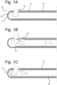
- Fig. 1 shows a cutting tip of an exemplary vitrectomy device.
- the cutting tip 10 comprises a hollow outer sheath 12, having a closed distal end 14.
- An inner tube 16 having an open distal end is disposed within the outer sheath 12.
- the inner tube 16 defines a lumen through which material can be aspirated from the eye and can thus be operatively coupled to a vacuum source (not shown) which is configured to draw material into the cutting tip 10 and through the lumen provided by the inner tube 16.
- the outer sheath 12 and the inner tube 16 are configured for relative movement with respect to each other between an first 'advanced' position in which the inner tube 16 is fully advanced within the outer sheath 12 (as shown in view A of Fig. 1 ) and a second ⁇ retracted' position (shown in view B of Fig. 1 ) in which the inner tube 16 is fully retracted with respect to the outer sheath 12.
- the outer sheath 12 comprises a first aperture 18 and the inner tube 16 comprises a second aperture 20.
- the first and second apertures 18, 20 are aligned and in register with each other (as shown in view A).
- the second aperture 20 is retracted with respect to the first aperture 18, such a distal edge of the second aperture 20 is moves at least to a position at which it meets a proximal edge of the first aperture 18 (as shown in view B).
- a distal end of the inner tube is positioned proximally (towards the user) of the first aperture 18, such that the first aperture 18 is not occluded by the inner tube 16.
- An edge of at least one of the first aperture 18 and the second aperture 20 forms a first cutting edge 22 such that tissue can be severed at the point where the cutting edge 22 meets an opposing surface formed by the edge of the other aperture (shown in view B).
- a first cutting edge 22 is formed at the distal edge of the second aperture 20 in the inner tube 16.
- a cutting edge may similarly be formed at a proximal edge of the first aperture 18, or that both apertures may comprises cutting edges.
- a second cutting edge 24 can also be formed at the open distal end of the inner tube 16, such that tissue drawn though the first aperture 18 with the inner tube 16 in the retracted position can be severed as the inner tube 16 returns to its advanced position.
- a cutting edge can alternatively or additionally be formed at the distal edge of the first aperture 18.
- the handheld portion of a vitrectomy tool comprises the cutting tip 10 described with reference to Fig. 1 and a housing 26.
- the housing 26 is shaped and sized for one-handed use by a healthcare professional, and comprises a generally elongate shape.
- the outer sheath 12 and the inner tube 16 extend into the housing 26.
- the outer sheath 12 is fixed with respect to the housing 26, whilst the inner tube 16 is slidably mounted therein.
- the inner tube 16 is operatively coupled to a reciprocator assembly 28, which is configured to oscillate back and forth to drive reciprocal movement of the inner tube 16 with respect to the sheath 12 in a cutting action, as described with reference to Fig. 1 .
- the reciprocator assembly 28 comprises a first chamber 30 and a second chamber 32 fluidically separated from each other by a flexible membrane or separator 34.
- the separator 34 comprises a linkage or coupling 36, which couples the separator 34 to the inner tube 16.
- the first chamber 30 is in fluid communication with a first conduit or pneumatic line 38 and the second chamber 32 is in fluid communication with a second conduit or pneumatic line 40.
- the pressure within the first and second chambers 30, 32 is alternately increased and decreased.
- the pressure differential between the first chamber 30 and the second chamber 32 biases the flexible membrane in a distal direction, the inner tube 16 moves distally with respect to the fixed outer sheath 12.
- the inner tube 16 moves proximally with respect to the outer sheath 12.
- the pressure differential between the first chamber 30 and the second chamber 12 is controlled via the first and second pneumatic lines 38, 40.
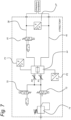
- the pneumatic lines 38, 40 are coupled to an actuation system 42 that alternately varies the pressure within the first and second chambers 30 and 32.
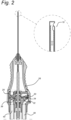
- the system 42 comprises a housing forming a chamber 44, which is fluidically separated by a diaphragm 46 into a first compartment 48 defining a first internal volume and a second compartment 50 defining a second internal volume.
- a first port 49 is provided in fluid communication with the first compartment 48 and is configured for connection to a first conduit 38.
- a second port 51 is provided in fluid communication with the second compartment 50, and is configured for connection to a second conduit 40.
- the diaphragm 46 is movably mounted within the chamber 44.
- the diaphragm can be formed of a flexible material (such as a thermoplastic elastomer or a rubber) and/or it may be fixed within the chamber with some slack to allow reciprocating movement.
- the diaphragm 46 shown in Fig. 3 is configured for alternate movement between a first position and a second position, such that movement from the first position to the second position decreases the first volume (in the first compartment 48) and increases the second volume (in the second compartment 50).
- movement of the diaphragm 46 in the opposite direction, from the second position to the first position increases the volume of the first compartment 48, and decreases the volume of the second compartment 50.
- the system further comprises a diaphragm actuator 52 configured to oscillate back and forth to move the diaphragm 46 between the first position and the second position and a drive system 54 configured to drive the oscillation of the diaphragm actuator 52.
- the drive system 54 can comprise a linear motor.
- the linear motor is linear oscillator motor configured to drive the diaphragm 46 back and forth at a desired frequency in response to an alternating control current or voltage supplied to the motor.
- the driver 54 can comprise a Lorentz-type actuator, also known as a Lorentz driver, e.g. implemented using a Tecnotion UL series linear motor.
- the driver 54 can comprise a reluctance motor. Further details of the driver 54 will be described below with reference to Figure 6 .
- Each of the first and second compartments 48, 50 can be coupled to an above-ambient air supply.
- each of the first and second compartments can be in fluid communication with a 1.5 bar air supply, e.g. via flow-restrictions R 1 and R 2 .
- the stiffness of the ⁇ gas spring' that drives the reciprocator in the handle housing 26 is increased, improving the responsiveness of the pneumatic system.
- above atmospheric pressure within the first and second compartments 48, 50 can allow the diaphragm to be biased into the first or second position if one of the compartments 48, 50 or one of the pneumatic lines 38, 40 is vented.
- the complete pneumatic system is a closed volume, and part of it is only vented when the retract valve 61 (see below) is opened. Therefore the air consumption of the total system is low, and a very small built-in compressor can suffice for the air supply, removing the need for an external air-supply line.
- a control loop can be implemented to provide the desired pressure levels within the first and second compartments 48, 50 (and thus within the chambers 30 and 32 of the handheld tool).
- the control loop can comprise an alternating current or voltage supply configured to drive the linear motor back and forth.
- the control loop can drive the actuator at an oscillating frequency of between 5-200 Hz, e.g. 166 Hz. This allows for a handheld vitrectomy tool that is operable at 10.000 movement per minute or more.
- the skilled person will appreciate that the oscillating frequency of the drive system 54 can continuously be varied depending on the requirements of the procedure, the architecture of the handheld device and the preference of the health care provider.
- control loop can further comprise one or more sensors to determine the oscillation of the diaphragm 46 within the chamber 44.
- a position sensor can be integrated to measure the position of the diaphragm 46 within the chamber 44.
- the position of the diaphragm 46 provides information regarding the relative volumes of the first and second compartments 48, 50, and thus the pressures supplied via pneumatic lines 38, 40.
- one or more pressure sensors can be incorporated into the actuation system.
- a pressure sensor P1 can be provided in fluid communication with the first compartment 48 to measure the pressure within the first compartment 48 and the first pneumatic line 38.
- a pressure sensor P2 can be provided in fluid communication with the second compartment 50 to measure the pressure within the second compartment and the second pneumatic line 40.
- a differential pressure sensor ⁇ P can be provided to measure the differential pressure between the first pneumatic line 38 and the second pneumatic line 40.
- the differential pressure sensor can be implemented to measure the differential pressure between the first and second compartments 48, 50, or it can be implemented to measure the differential pressure between the first and second conduits 38, 40, close to the handheld device.
- the pressure sensors connected to each compartment allow monitoring of the achieved pressure difference between the first and second compartments 48, 50.
- Each pressure sensor alone or in combination, can allow verification for proper functioning and can be used for controller feedback.
- the actuation system further comprises a retract valve 61 configured to move the diaphragm 34 to the first position upon deactivation of the drive system.
- a retract valve arrangement can advantageously allow the neutral position of the diaphragm to correspond to an intermediate position of the inner tube 16 with respect to the outer sheath 12, without compromising the aspiration flow through the cutting opening whilst the cutting blade is at rest (with the motor deactivated). This is because the retract valve vents one compartment/pneumatic line whilst the other is maintained at 1.5bar.
- Such a retract valve 61 could be a regular 3/2 solenoid valve shown in Fig. 3 , or alternatively a set of 2/2 solenoid valves, arranged such that conduit 38 can be vented to ambient pressure, and the supply from volume 48 can be blocked.
- vent valves can also be provided to vent gas from the first and second compartments 48, 50 at a predetermined pressure level or within a predetermined pressure range.
- An exemplary pneumatic system comprising a series of vent valves and a retract valve will be described in more detail with reference to Figure 7 .
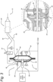
- the driver 54 can comprises a coil 60 configured to be energised by an applied current or voltage, and an array of magnets 62 (e.g. a Hallbach array).
- the array of magnets can be configured as the stator, or it can be configured as mover in the drive system 54 of the present invention.
- a guide element for example a flexible element such as a radial spring 66, is provided to guide the mover in reciprocating linear motion.
- the moving part of the motor (the array or the coil) is coupled to the diaphragm actuator 52 directly or via a linkage 56.
- the diaphragm actuator 52 is positioned within the chamber 44.
- the diaphragm actuator 52 can engage the membrane 46 in different ways.
- the diaphragm actuator 52 can be securely fastened to the diaphragm with adhesive, or it may comprise opposing parts between which the diaphragm is clamped.
- the diaphragm actuator 52 can be partially embedded within the material of the diaphragm 46.
- the stator is positioned outside of the chamber 44, and a coupling 56 extends through a wall of the chamber 44 into the first compartment 48.
- a seal 58 seals the opening in the chamber wall through which the coupling 56 extends.
- an additional opening (not shown) can be provided in second compartment 50, comprising a seal similar to seal 58. The additional opening can be provided to approximate or mirror the leakage experienced through the seal 58, to offset any imbalance in the pressure due to leakage from the first compartment 48.
- the coupling between the membrane actuator 52, the coupling 56, and the mover can be adapted to suit the requirements of the system, and that these components may also be formed as a single part.
- Figure 5 shows a further aspect of the invention in which the configuration of the driver 54 and the first and second compartments 48, 50 differs from the arrangement shown in Figure 4 .
- an ophthalmic cutting tool actuation system in accordance with a second aspect of the invention comprises a housing 44' having a first compartment 48' at least partially defined by a first diaphragm 46a and having a first internal volume.
- a second compartment 50' is at least partially defined by a second diaphragm 46b and has a second internal volume.
- a first port is provided in fluid communication with the first compartment 48' and is configured for connection to a first conduit connected to a handheld ophthalmic cutting tool, in the manner described in connection with Figures 2 and 3 .
- a second port is provided in fluid communication with the second compartment 50', and is configured for connection to a second conduit connected to the ophthalmic cutting tool.
- the first diaphragm 46a is movably mounted with respect to the housing 44', and is configured for alternate movement between a first position and a second position, such that movement of the first diaphragm 46a from its first position to its second position decreases the first volume of the first compartment 48'.
- the second diaphragm 46b is similarly movably mounted with respect to the housing 44', and is configured for alternate movement between a first position and a second position, such that movement of the second diaphragm 46b from its first position to its second position increases the second volume of the second compartment 50'.
- the system further comprises a diaphragm actuator 52' configured to oscillate back and forth to move the first diaphragm 46a and the second diaphragm 46b simultaneously between the first position and the second position.
- a drive system 54' disposed within the housing 44' in the embodiment shown in Figure 5 , is configured to drive the oscillation of the diaphragm actuator 52'.
- the first and second diaphragms 46a, 46b can be separated by a space within the housing 44', and the drive system 54' can be at least partially disposed within the space between the first and second diaphragms 46a, 46b.
- This provides a simple construction for the actuator 52' and allows reciprocating movement of the motor to the transmitted directly to the parts 52a, 52b of the diaphragm actuator 52'.
- the drive system 54' can be configured in a similar manner to the drive system 54 described with reference to Figure 4 and can comprise a linear motor comprising a coil and a Hallbach array.
- the motor can comprise a Lorentz driver or a reluctance motor.
- the diaphragm actuator 52' can comprise multiple parts or can be formed as a single piece, driven by the mover.
- the diaphragm actuator 52' comprises a first diaphragm actuator 52a that clamps the first diaphragm 46a, and a second diaphragm actuator 52b that clamps the second diaphragm 46b.
- a common coupling 56' can fixedly connect the two parts 52a, 52b.
- the common coupling can be integrally formed with or connected to the mover actuator of the motor.
- the drive system 54 comprises first and second flexible guiding element 66a, 66b to guide the linear motion of the actuator.
- a control loop can be provided that comprising a position sensor configured to monitor the position of at least one of the first and second diaphragms within the housing.
- pressure sensors can be provided to measure the pressure within one or both of the first and second compartments 48', 50'.
- the system can comprise a first pressure sensor configured to measure the pressure within the first compartment and a second pressure sensor configured to monitor the pressure within the second compartment.
- First and second vent valves can also be provided in the arrangement shown in Figure 5 , to vent the first and second compartments 48', 50' should a predetermined maximum pressure be reached.
- a differential pressure sensor can be provided to measure the differential pressure between the first and second compartments.
- a retract valve 61 can also be incorporated into the system shown in Figure 5 (similar as in the embodiment described with reference to Fig. 3 above), configured to move the diaphragm 34 (and the inner tube 16) to its respective first position upon deactivation of the drive system.
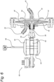
- FIG. 6 shows in more detail a drive system 54 and a chamber 44 in accordance with an embodiment of the present invention.
- the drive system 54 comprises a linear motor having a mover-coil 60 and a Hallbach array 62 forming the stator.
- the magnets of the Hallbach array are mounted on back-irons 64.
- the mover-coil 60 is coupled via linkage 56 to the diaphragm actuator 52, which in the embodiment shown in Figure 6 is partially embedded within the material of the diaphragm 46.
- An optical sensor 68 is configured to measure the position of the stator 62 relative to the coil 60, and thus the position of the diaphragm actuator 52 within the chamber 44.
- Straight-guidance flexures 66 are fixedly coupled to the mover-coil 60 to ensure that the mover-coil moves back and forth in a straight line.
- the mover-coil 60 can further comprise cooling fins to dissipate heat generated during use.
- the chamber 44, diaphragm 46 and diaphragm actuator 52 can be configured to minimise the air-volume within the first and second compartments 48, 50.
- the minimised chamber volume results in the largest compression ratio (ratio of neutral volume to compressed volume).
- the stroke of the motor in the exemplary embodiment shown in Figure 6 is approximately 4mm (2mm in a first direction from a neutral rest position, and 2mm in an opposite direction away from the neutral rest position).
- the total air volume of the chamber (consisting of the air volume of the first and second compartments) is approximately 20ml.
- Such a configuration allows a maximum differential pressure within the first and second compartments of the chamber of approximately 1000mbar, while the preferred working range is between 300 and 700mbar.
- the seal 58 comprises a sealing bellow.
- the sealing bellow allows the motion of the coupling 56 to be transferred through the chamber wall to the diaphragm 46, without sliding components and without leakage.
- Figure 8 shows a side view of an exemplary embodiment of the mover-coil 60 as can be used in the present invention drive system 54. Together with a set of permanent magnets (e.g. as part of the stator 62 as described above), this mover-coil 60 forms the motor that drives the present invention actuation system embodiments.
- the mover-coil 60 comprises a (flat wound) coil 63 which is wound around a core (not visible in Figure 8 ), and then inserted in an aluminum frame 67. It is then filled with a casting resin, forming a casting compound 65, and the core is removed. Connection leads 63a are provided at the bottom of the coil 63 in the embodiment shown.
- the frame 67 comprises attachment points 57 for the coupling 56 to the diaphragm actuator 52, as well as an extension 69 for cooperation with the (optical) sensor 68.
- the casting compound 65 comprises several extensions 65b into the frame 67 for providing a rigid structure, as well as a bridge part 65a which is provided in the center at the height of the attachment points 57.
- the bridge part 65a allows forces to be transferred in-line with the point where the forces act, without adding too much mass.
- the frame 67 is provided with cooling fins 67a, having a cutout up to a maximum of halfway the width of the frame 67 such that the motor frame 67 is stiffer and can support the forces better.
- the structure of the mover-coil 60 having the bridge part 65a in the center of casting compound 65 effectively prevent damage to the mover-coil 60.
- a much lower acoustic noise production at the same motor amplitude is provided.
- This is accomplished by the combination of frame 67 and casting compound 65 having a stiffer structure, such that the parasitic vibrations (other than the linear motion in the direction along coupling 56), have a much lower amplitude.
- the lower noise level is beneficial for the user who works for long periods near the actuation system of the present invention.
- a further advantage is that the drive system 54 amplitude (and therefore the actuation pressure to the instrument) can be increased, without producing excessive noise levels.
- the control system comprises pressure sensors P1 and P2, in fluid communication with the first and second compartments of chamber 44 respectively.
- Pressure sensors P1 and P2 are absolute pressure sensors.
- Differential pressure sensor ⁇ P is arranged between the first and second pneumatic lines 38, 40 and is configured to monitor the differential pressure within the system. By configuring the differential pressure sensor ⁇ P to measure the differential pressure between the first and second pneumatic lines 38, 40, the achieved pressure differential close to the reciprocator 28 is observed.
- a bias pressure inlet 74 comprising a pressure regulator is also provided to supply above-atmospheric pressure supplied to the chamber 44 (e.g. 1.5bar).
- the above atmospheric pressure leads to increased stiffness of the effective gas spring that drives the reciprocator 28 within the hand-held device.
- a bias pressure inlet valve 72 and a bias pressure vent valve 70 are provided to apply the bias pressure before use, and vent it to a safe state after use respectively.
- the supply to the chamber 44 is maintained at 1.5bar.
- An allowable error range in this respect would be 0... +0.2 mbar, i.e. 1.5 to 1.7 bar.
- a retract valve 61 can be provided in fluid communication with one of the first and second pneumatic lines 38, 40.
- the retract valve 61 is provided in communication with the first pneumatic line.
- the retract valve 61 is configured to vent one of the pneumatic lines 38, 40.
- the bias pressure supplied by the system through the other (un-vented) pneumatic line pushes the actuator in the hand-held device to one end (see Figures 1A-C ) to ensure that the first aperture in the outer sheath is not occluded by the inner sheath, thereby allowing maximum flow through the inner tube when a cutting action is not used.
- an SMC VDW 250 3/2 valve is applied, which is a commercially available valve.
- the retract valve 61 is configured to bias the diaphragm 46 in a direction that results in retraction of the inner tube 16 to its maximum extent within the outer sheath 12 when the cutting operation is ceased.
- the retract valve 61 can be configured to bias the inner tube 16 distally towards its maximum distal extent.
- the extreme distal or extreme proximal location of the inner tube 16 relative to the outer sheath 12 means that the first opening 18 in communication with the aspiration lumen is (substantially) not occluded to allow free flow of material (including severed material and fluid) through the lumen of the inner tube 16.
Landscapes
- Health & Medical Sciences (AREA)
- Ophthalmology & Optometry (AREA)
- Life Sciences & Earth Sciences (AREA)
- Animal Behavior & Ethology (AREA)
- Engineering & Computer Science (AREA)
- Biomedical Technology (AREA)
- Heart & Thoracic Surgery (AREA)
- Vascular Medicine (AREA)
- Nuclear Medicine, Radiotherapy & Molecular Imaging (AREA)
- Surgery (AREA)
- General Health & Medical Sciences (AREA)
- Public Health (AREA)
- Veterinary Medicine (AREA)
- External Artificial Organs (AREA)
- Reciprocating Pumps (AREA)
- Surgical Instruments (AREA)
Applications Claiming Priority (2)
| Application Number | Priority Date | Filing Date | Title |
|---|---|---|---|
| NL2022011A NL2022011B1 (en) | 2018-11-16 | 2018-11-16 | Vitrectome actuator |
| PCT/NL2019/050741 WO2020101489A1 (en) | 2018-11-16 | 2019-11-14 | Vitrectome actuator |
Publications (3)
| Publication Number | Publication Date |
|---|---|
| EP3880141A1 EP3880141A1 (en) | 2021-09-22 |
| EP3880141C0 EP3880141C0 (en) | 2023-08-09 |
| EP3880141B1 true EP3880141B1 (en) | 2023-08-09 |
Family
ID=64607273
Family Applications (1)
| Application Number | Title | Priority Date | Filing Date |
|---|---|---|---|
| EP19806064.2A Active EP3880141B1 (en) | 2018-11-16 | 2019-11-14 | Vitrectome actuator and cutting tool |
Country Status (6)
| Country | Link |
|---|---|
| US (1) | US12343286B2 (es) |
| EP (1) | EP3880141B1 (es) |
| JP (1) | JP7434318B2 (es) |
| ES (1) | ES2961926T3 (es) |
| NL (1) | NL2022011B1 (es) |
| WO (1) | WO2020101489A1 (es) |
Families Citing this family (2)
| Publication number | Priority date | Publication date | Assignee | Title |
|---|---|---|---|---|
| IT202000009049A1 (it) * | 2020-04-27 | 2021-10-27 | Marco Codenotti | Dispositivo per chirurugia vitreo-retinica |
| EP4615378A1 (en) * | 2022-11-08 | 2025-09-17 | Alcon Inc. | High frequency vitrector |
Family Cites Families (19)
| Publication number | Priority date | Publication date | Assignee | Title |
|---|---|---|---|---|
| US5106364A (en) | 1989-07-07 | 1992-04-21 | Kabushiki Kaisha Topcon | Surgical cutter |
| US5284472A (en) * | 1992-10-30 | 1994-02-08 | Allergan, Inc. | Vitreous cutter |
| US5980546A (en) * | 1998-04-13 | 1999-11-09 | Nexus Medical System, Inc. Llc | Guillotine cutter used with medical procedures |
| US20070173870A2 (en) * | 2005-10-18 | 2007-07-26 | Jaime Zacharias | Precision Surgical System |
| US20070225781A1 (en) * | 2006-03-21 | 2007-09-27 | Nidus Medical, Llc | Apparatus and methods for altering temperature in a region within the body |
| DE102006014339A1 (de) * | 2006-03-28 | 2007-10-11 | Siemens Ag | Endoskopiekapsel sowie Endoskopie-System und Verfahren zur Therapie mittels einer Endoskopiekapsel |
| JP2010535039A (ja) | 2007-08-01 | 2010-11-18 | アルコン リサーチ, リミテッド | 使い捨て眼科用注射装置 |
| US8080029B2 (en) * | 2007-09-21 | 2011-12-20 | Novartis Ag | System for actuation of a vitreous cutter |
| US20090131832A1 (en) * | 2007-11-20 | 2009-05-21 | Innovamedica S.A.P.I. De C.V. | Electronic Syringe with Safety System for Spinal Injection |
| JP5231902B2 (ja) * | 2008-09-02 | 2013-07-10 | 株式会社ニデック | 硝子体手術装置 |
| US8328835B2 (en) * | 2008-12-08 | 2012-12-11 | Bausch & Lomb Incorporated | System for operating and controlling a pneumatically driven vitrectomy probe |
| CN102652006B (zh) * | 2009-12-10 | 2014-06-11 | 爱尔康研究有限公司 | 用于动态气动阀驱动器的系统和方法 |
| US8821524B2 (en) * | 2010-05-27 | 2014-09-02 | Alcon Research, Ltd. | Feedback control of on/off pneumatic actuators |
| US8888802B2 (en) | 2010-12-21 | 2014-11-18 | Alcon Research, Ltd. | Vitrectomy probe with adjustable cutter port size |
| US8540743B2 (en) * | 2010-12-22 | 2013-09-24 | Alcon Research, Ltd. | Hydraulic vitrectomy probe |
| US8496681B2 (en) | 2011-06-06 | 2013-07-30 | Synergetics, Inc. | Systems and methods for vitrectomy |
| US20130144317A1 (en) | 2011-12-01 | 2013-06-06 | Salomon Valencia | Position feedback control for a vitrectomy probe |
| AU2018224401A1 (en) | 2017-02-27 | 2019-07-18 | Alcon Inc. | Reciprocating surgical tool with inertial damper |
| US10893978B2 (en) * | 2017-12-14 | 2021-01-19 | Alcon Inc. | Vitreous cutter pneumatic driver |
-
2018
- 2018-11-16 NL NL2022011A patent/NL2022011B1/en active
-
2019
- 2019-11-14 ES ES19806064T patent/ES2961926T3/es active Active
- 2019-11-14 EP EP19806064.2A patent/EP3880141B1/en active Active
- 2019-11-14 US US17/285,517 patent/US12343286B2/en active Active
- 2019-11-14 JP JP2021526655A patent/JP7434318B2/ja active Active
- 2019-11-14 WO PCT/NL2019/050741 patent/WO2020101489A1/en not_active Ceased
Also Published As
| Publication number | Publication date |
|---|---|
| JP2022507580A (ja) | 2022-01-18 |
| WO2020101489A1 (en) | 2020-05-22 |
| US12343286B2 (en) | 2025-07-01 |
| EP3880141C0 (en) | 2023-08-09 |
| JP7434318B2 (ja) | 2024-02-20 |
| EP3880141A1 (en) | 2021-09-22 |
| US20210386587A1 (en) | 2021-12-16 |
| NL2022011B1 (en) | 2020-05-26 |
| ES2961926T3 (es) | 2024-03-14 |
Similar Documents
| Publication | Publication Date | Title |
|---|---|---|
| CN106132363B (zh) | 极小的脉动眼科探针 | |
| US10918411B2 (en) | Vitrectomy probe with integral valve | |
| JP5819982B2 (ja) | 液圧式硝子体切除プローブ | |
| US8080029B2 (en) | System for actuation of a vitreous cutter | |
| US9101442B2 (en) | Reduced friction vitrectomy probe | |
| JP5112747B2 (ja) | 眼科外科システム | |
| US20070129732A1 (en) | Spring-Mass Surgical System | |
| EP1857083A1 (en) | Surgical system having integral pneumatic manifolds | |
| US10758411B2 (en) | Reciprocating surgical tool with inertial damper | |
| EP3641709B1 (en) | Electronically actuated reciprocating surgical instrument | |
| EP3880141B1 (en) | Vitrectome actuator and cutting tool | |
| US12059373B2 (en) | Fluid driven vitrectomy probe | |
| KR20250047728A (ko) | 유리체 절제술 커터 |
Legal Events
| Date | Code | Title | Description |
|---|---|---|---|
| STAA | Information on the status of an ep patent application or granted ep patent |
Free format text: STATUS: UNKNOWN |
|
| STAA | Information on the status of an ep patent application or granted ep patent |
Free format text: STATUS: THE INTERNATIONAL PUBLICATION HAS BEEN MADE |
|
| PUAI | Public reference made under article 153(3) epc to a published international application that has entered the european phase |
Free format text: ORIGINAL CODE: 0009012 |
|
| STAA | Information on the status of an ep patent application or granted ep patent |
Free format text: STATUS: REQUEST FOR EXAMINATION WAS MADE |
|
| 17P | Request for examination filed |
Effective date: 20210527 |
|
| AK | Designated contracting states |
Kind code of ref document: A1 Designated state(s): AL AT BE BG CH CY CZ DE DK EE ES FI FR GB GR HR HU IE IS IT LI LT LU LV MC MK MT NL NO PL PT RO RS SE SI SK SM TR |
|
| DAV | Request for validation of the european patent (deleted) | ||
| DAX | Request for extension of the european patent (deleted) | ||
| GRAP | Despatch of communication of intention to grant a patent |
Free format text: ORIGINAL CODE: EPIDOSNIGR1 |
|
| STAA | Information on the status of an ep patent application or granted ep patent |
Free format text: STATUS: GRANT OF PATENT IS INTENDED |
|
| INTG | Intention to grant announced |
Effective date: 20221012 |
|
| GRAJ | Information related to disapproval of communication of intention to grant by the applicant or resumption of examination proceedings by the epo deleted |
Free format text: ORIGINAL CODE: EPIDOSDIGR1 |
|
| STAA | Information on the status of an ep patent application or granted ep patent |
Free format text: STATUS: REQUEST FOR EXAMINATION WAS MADE |
|
| GRAP | Despatch of communication of intention to grant a patent |
Free format text: ORIGINAL CODE: EPIDOSNIGR1 |
|
| STAA | Information on the status of an ep patent application or granted ep patent |
Free format text: STATUS: GRANT OF PATENT IS INTENDED |
|
| INTC | Intention to grant announced (deleted) | ||
| INTG | Intention to grant announced |
Effective date: 20230307 |
|
| GRAS | Grant fee paid |
Free format text: ORIGINAL CODE: EPIDOSNIGR3 |
|
| GRAA | (expected) grant |
Free format text: ORIGINAL CODE: 0009210 |
|
| STAA | Information on the status of an ep patent application or granted ep patent |
Free format text: STATUS: THE PATENT HAS BEEN GRANTED |
|
| AK | Designated contracting states |
Kind code of ref document: B1 Designated state(s): AL AT BE BG CH CY CZ DE DK EE ES FI FR GB GR HR HU IE IS IT LI LT LU LV MC MK MT NL NO PL PT RO RS SE SI SK SM TR |
|
| REG | Reference to a national code |
Ref country code: GB Ref legal event code: FG4D |
|
| REG | Reference to a national code |
Ref country code: CH Ref legal event code: EP |
|
| REG | Reference to a national code |
Ref country code: IE Ref legal event code: FG4D |
|
| REG | Reference to a national code |
Ref country code: DE Ref legal event code: R096 Ref document number: 602019034734 Country of ref document: DE |
|
| U01 | Request for unitary effect filed |
Effective date: 20230904 |
|
| U07 | Unitary effect registered |
Designated state(s): AT BE BG DE DK EE FI FR IT LT LU LV MT NL PT SE SI Effective date: 20230908 |
|
| U20 | Renewal fee for the european patent with unitary effect paid |
Year of fee payment: 5 Effective date: 20231106 |
|
| PG25 | Lapsed in a contracting state [announced via postgrant information from national office to epo] |
Ref country code: GR Free format text: LAPSE BECAUSE OF FAILURE TO SUBMIT A TRANSLATION OF THE DESCRIPTION OR TO PAY THE FEE WITHIN THE PRESCRIBED TIME-LIMIT Effective date: 20231110 |
|
| PG25 | Lapsed in a contracting state [announced via postgrant information from national office to epo] |
Ref country code: IS Free format text: LAPSE BECAUSE OF FAILURE TO SUBMIT A TRANSLATION OF THE DESCRIPTION OR TO PAY THE FEE WITHIN THE PRESCRIBED TIME-LIMIT Effective date: 20231209 |
|
| PG25 | Lapsed in a contracting state [announced via postgrant information from national office to epo] |
Ref country code: RS Free format text: LAPSE BECAUSE OF FAILURE TO SUBMIT A TRANSLATION OF THE DESCRIPTION OR TO PAY THE FEE WITHIN THE PRESCRIBED TIME-LIMIT Effective date: 20230809 Ref country code: NO Free format text: LAPSE BECAUSE OF FAILURE TO SUBMIT A TRANSLATION OF THE DESCRIPTION OR TO PAY THE FEE WITHIN THE PRESCRIBED TIME-LIMIT Effective date: 20231109 Ref country code: IS Free format text: LAPSE BECAUSE OF FAILURE TO SUBMIT A TRANSLATION OF THE DESCRIPTION OR TO PAY THE FEE WITHIN THE PRESCRIBED TIME-LIMIT Effective date: 20231209 Ref country code: HR Free format text: LAPSE BECAUSE OF FAILURE TO SUBMIT A TRANSLATION OF THE DESCRIPTION OR TO PAY THE FEE WITHIN THE PRESCRIBED TIME-LIMIT Effective date: 20230809 Ref country code: GR Free format text: LAPSE BECAUSE OF FAILURE TO SUBMIT A TRANSLATION OF THE DESCRIPTION OR TO PAY THE FEE WITHIN THE PRESCRIBED TIME-LIMIT Effective date: 20231110 |
|
| PG25 | Lapsed in a contracting state [announced via postgrant information from national office to epo] |
Ref country code: PL Free format text: LAPSE BECAUSE OF FAILURE TO SUBMIT A TRANSLATION OF THE DESCRIPTION OR TO PAY THE FEE WITHIN THE PRESCRIBED TIME-LIMIT Effective date: 20230809 |
|
| REG | Reference to a national code |
Ref country code: ES Ref legal event code: FG2A Ref document number: 2961926 Country of ref document: ES Kind code of ref document: T3 Effective date: 20240314 |
|
| PG25 | Lapsed in a contracting state [announced via postgrant information from national office to epo] |
Ref country code: SM Free format text: LAPSE BECAUSE OF FAILURE TO SUBMIT A TRANSLATION OF THE DESCRIPTION OR TO PAY THE FEE WITHIN THE PRESCRIBED TIME-LIMIT Effective date: 20230809 Ref country code: RO Free format text: LAPSE BECAUSE OF FAILURE TO SUBMIT A TRANSLATION OF THE DESCRIPTION OR TO PAY THE FEE WITHIN THE PRESCRIBED TIME-LIMIT Effective date: 20230809 Ref country code: CZ Free format text: LAPSE BECAUSE OF FAILURE TO SUBMIT A TRANSLATION OF THE DESCRIPTION OR TO PAY THE FEE WITHIN THE PRESCRIBED TIME-LIMIT Effective date: 20230809 Ref country code: SK Free format text: LAPSE BECAUSE OF FAILURE TO SUBMIT A TRANSLATION OF THE DESCRIPTION OR TO PAY THE FEE WITHIN THE PRESCRIBED TIME-LIMIT Effective date: 20230809 |
|
| REG | Reference to a national code |
Ref country code: DE Ref legal event code: R097 Ref document number: 602019034734 Country of ref document: DE |
|
| PLBE | No opposition filed within time limit |
Free format text: ORIGINAL CODE: 0009261 |
|
| STAA | Information on the status of an ep patent application or granted ep patent |
Free format text: STATUS: NO OPPOSITION FILED WITHIN TIME LIMIT |
|
| PG25 | Lapsed in a contracting state [announced via postgrant information from national office to epo] |
Ref country code: MC Free format text: LAPSE BECAUSE OF FAILURE TO SUBMIT A TRANSLATION OF THE DESCRIPTION OR TO PAY THE FEE WITHIN THE PRESCRIBED TIME-LIMIT Effective date: 20230809 |
|
| 26N | No opposition filed |
Effective date: 20240513 |
|
| PG25 | Lapsed in a contracting state [announced via postgrant information from national office to epo] |
Ref country code: MC Free format text: LAPSE BECAUSE OF FAILURE TO SUBMIT A TRANSLATION OF THE DESCRIPTION OR TO PAY THE FEE WITHIN THE PRESCRIBED TIME-LIMIT Effective date: 20230809 |
|
| REG | Reference to a national code |
Ref country code: IE Ref legal event code: MM4A |
|
| PG25 | Lapsed in a contracting state [announced via postgrant information from national office to epo] |
Ref country code: IE Free format text: LAPSE BECAUSE OF NON-PAYMENT OF DUE FEES Effective date: 20231114 |
|
| PG25 | Lapsed in a contracting state [announced via postgrant information from national office to epo] |
Ref country code: IE Free format text: LAPSE BECAUSE OF NON-PAYMENT OF DUE FEES Effective date: 20231114 |
|
| U20 | Renewal fee for the european patent with unitary effect paid |
Year of fee payment: 6 Effective date: 20241113 |
|
| PG25 | Lapsed in a contracting state [announced via postgrant information from national office to epo] |
Ref country code: CY Free format text: LAPSE BECAUSE OF FAILURE TO SUBMIT A TRANSLATION OF THE DESCRIPTION OR TO PAY THE FEE WITHIN THE PRESCRIBED TIME-LIMIT; INVALID AB INITIO Effective date: 20191114 |
|
| PG25 | Lapsed in a contracting state [announced via postgrant information from national office to epo] |
Ref country code: HU Free format text: LAPSE BECAUSE OF FAILURE TO SUBMIT A TRANSLATION OF THE DESCRIPTION OR TO PAY THE FEE WITHIN THE PRESCRIBED TIME-LIMIT; INVALID AB INITIO Effective date: 20191114 |
|
| REG | Reference to a national code |
Ref country code: CH Ref legal event code: U11 Free format text: ST27 STATUS EVENT CODE: U-0-0-U10-U11 (AS PROVIDED BY THE NATIONAL OFFICE) Effective date: 20251201 |
|
| PG25 | Lapsed in a contracting state [announced via postgrant information from national office to epo] |
Ref country code: TR Free format text: LAPSE BECAUSE OF FAILURE TO SUBMIT A TRANSLATION OF THE DESCRIPTION OR TO PAY THE FEE WITHIN THE PRESCRIBED TIME-LIMIT Effective date: 20230809 |
|
| U20 | Renewal fee for the european patent with unitary effect paid |
Year of fee payment: 7 Effective date: 20251121 |
|
| PGFP | Annual fee paid to national office [announced via postgrant information from national office to epo] |
Ref country code: GB Payment date: 20251125 Year of fee payment: 7 |
|
| PGFP | Annual fee paid to national office [announced via postgrant information from national office to epo] |
Ref country code: CH Payment date: 20251201 Year of fee payment: 7 |
|
| PGFP | Annual fee paid to national office [announced via postgrant information from national office to epo] |
Ref country code: ES Payment date: 20251209 Year of fee payment: 7 |