EP3879904B1 - Self-contained time division duplex (tdd) subframe structure - Google Patents
Self-contained time division duplex (tdd) subframe structure Download PDFInfo
- Publication number
- EP3879904B1 EP3879904B1 EP21169533.3A EP21169533A EP3879904B1 EP 3879904 B1 EP3879904 B1 EP 3879904B1 EP 21169533 A EP21169533 A EP 21169533A EP 3879904 B1 EP3879904 B1 EP 3879904B1
- Authority
- EP
- European Patent Office
- Prior art keywords
- subframe
- data
- information
- control
- scheduling
- Prior art date
- Legal status (The legal status is an assumption and is not a legal conclusion. Google has not performed a legal analysis and makes no representation as to the accuracy of the status listed.)
- Active
Links
- 230000005540 biological transmission Effects 0.000 claims description 90
- 238000000034 method Methods 0.000 claims description 49
- 238000004891 communication Methods 0.000 claims description 34
- 238000012545 processing Methods 0.000 description 37
- 238000010586 diagram Methods 0.000 description 14
- 230000006870 function Effects 0.000 description 12
- 230000008569 process Effects 0.000 description 10
- 238000001228 spectrum Methods 0.000 description 10
- 230000001413 cellular effect Effects 0.000 description 6
- 238000013461 design Methods 0.000 description 5
- 238000005516 engineering process Methods 0.000 description 4
- 238000012795 verification Methods 0.000 description 4
- 230000001360 synchronised effect Effects 0.000 description 3
- 239000000969 carrier Substances 0.000 description 2
- 230000000295 complement effect Effects 0.000 description 2
- 238000004590 computer program Methods 0.000 description 2
- 125000004122 cyclic group Chemical group 0.000 description 2
- 230000008520 organization Effects 0.000 description 2
- 241000760358 Enodes Species 0.000 description 1
- 238000003491 array Methods 0.000 description 1
- 230000008901 benefit Effects 0.000 description 1
- 239000003795 chemical substances by application Substances 0.000 description 1
- 239000004020 conductor Substances 0.000 description 1
- 230000008878 coupling Effects 0.000 description 1
- 238000010168 coupling process Methods 0.000 description 1
- 238000005859 coupling reaction Methods 0.000 description 1
- 230000002349 favourable effect Effects 0.000 description 1
- 239000000945 filler Substances 0.000 description 1
- 230000036541 health Effects 0.000 description 1
- 230000000977 initiatory effect Effects 0.000 description 1
- 230000007774 longterm Effects 0.000 description 1
- 238000010295 mobile communication Methods 0.000 description 1
- 230000003287 optical effect Effects 0.000 description 1
- 239000005022 packaging material Substances 0.000 description 1
- 230000002093 peripheral effect Effects 0.000 description 1
- 238000004886 process control Methods 0.000 description 1
- 230000001105 regulatory effect Effects 0.000 description 1
- 230000011664 signaling Effects 0.000 description 1
Images


Classifications
-
- H—ELECTRICITY
- H04—ELECTRIC COMMUNICATION TECHNIQUE
- H04W—WIRELESS COMMUNICATION NETWORKS
- H04W72/00—Local resource management
- H04W72/04—Wireless resource allocation
- H04W72/044—Wireless resource allocation based on the type of the allocated resource
- H04W72/0446—Resources in time domain, e.g. slots or frames
-
- H—ELECTRICITY
- H04—ELECTRIC COMMUNICATION TECHNIQUE
- H04L—TRANSMISSION OF DIGITAL INFORMATION, e.g. TELEGRAPHIC COMMUNICATION
- H04L1/00—Arrangements for detecting or preventing errors in the information received
- H04L1/12—Arrangements for detecting or preventing errors in the information received by using return channel
- H04L1/16—Arrangements for detecting or preventing errors in the information received by using return channel in which the return channel carries supervisory signals, e.g. repetition request signals
- H04L1/18—Automatic repetition systems, e.g. Van Duuren systems
- H04L1/1812—Hybrid protocols; Hybrid automatic repeat request [HARQ]
-
- H—ELECTRICITY
- H04—ELECTRIC COMMUNICATION TECHNIQUE
- H04L—TRANSMISSION OF DIGITAL INFORMATION, e.g. TELEGRAPHIC COMMUNICATION
- H04L1/00—Arrangements for detecting or preventing errors in the information received
- H04L1/12—Arrangements for detecting or preventing errors in the information received by using return channel
- H04L1/16—Arrangements for detecting or preventing errors in the information received by using return channel in which the return channel carries supervisory signals, e.g. repetition request signals
- H04L1/18—Automatic repetition systems, e.g. Van Duuren systems
- H04L1/1829—Arrangements specially adapted for the receiver end
- H04L1/1861—Physical mapping arrangements
-
- H—ELECTRICITY
- H04—ELECTRIC COMMUNICATION TECHNIQUE
- H04L—TRANSMISSION OF DIGITAL INFORMATION, e.g. TELEGRAPHIC COMMUNICATION
- H04L1/00—Arrangements for detecting or preventing errors in the information received
- H04L1/12—Arrangements for detecting or preventing errors in the information received by using return channel
- H04L1/16—Arrangements for detecting or preventing errors in the information received by using return channel in which the return channel carries supervisory signals, e.g. repetition request signals
- H04L1/18—Automatic repetition systems, e.g. Van Duuren systems
- H04L1/1867—Arrangements specially adapted for the transmitter end
- H04L1/1887—Scheduling and prioritising arrangements
-
- H—ELECTRICITY
- H04—ELECTRIC COMMUNICATION TECHNIQUE
- H04L—TRANSMISSION OF DIGITAL INFORMATION, e.g. TELEGRAPHIC COMMUNICATION
- H04L5/00—Arrangements affording multiple use of the transmission path
- H04L5/003—Arrangements for allocating sub-channels of the transmission path
- H04L5/0053—Allocation of signaling, i.e. of overhead other than pilot signals
- H04L5/0055—Physical resource allocation for ACK/NACK
-
- H—ELECTRICITY
- H04—ELECTRIC COMMUNICATION TECHNIQUE
- H04L—TRANSMISSION OF DIGITAL INFORMATION, e.g. TELEGRAPHIC COMMUNICATION
- H04L5/00—Arrangements affording multiple use of the transmission path
- H04L5/003—Arrangements for allocating sub-channels of the transmission path
- H04L5/0078—Timing of allocation
- H04L5/0082—Timing of allocation at predetermined intervals
-
- H—ELECTRICITY
- H04—ELECTRIC COMMUNICATION TECHNIQUE
- H04L—TRANSMISSION OF DIGITAL INFORMATION, e.g. TELEGRAPHIC COMMUNICATION
- H04L5/00—Arrangements affording multiple use of the transmission path
- H04L5/0091—Signaling for the administration of the divided path
-
- H—ELECTRICITY
- H04—ELECTRIC COMMUNICATION TECHNIQUE
- H04L—TRANSMISSION OF DIGITAL INFORMATION, e.g. TELEGRAPHIC COMMUNICATION
- H04L5/00—Arrangements affording multiple use of the transmission path
- H04L5/14—Two-way operation using the same type of signal, i.e. duplex
-
- H—ELECTRICITY
- H04—ELECTRIC COMMUNICATION TECHNIQUE
- H04L—TRANSMISSION OF DIGITAL INFORMATION, e.g. TELEGRAPHIC COMMUNICATION
- H04L5/00—Arrangements affording multiple use of the transmission path
- H04L5/14—Two-way operation using the same type of signal, i.e. duplex
- H04L5/1469—Two-way operation using the same type of signal, i.e. duplex using time-sharing
-
- H—ELECTRICITY
- H04—ELECTRIC COMMUNICATION TECHNIQUE
- H04W—WIRELESS COMMUNICATION NETWORKS
- H04W72/00—Local resource management
- H04W72/20—Control channels or signalling for resource management
-
- H—ELECTRICITY
- H04—ELECTRIC COMMUNICATION TECHNIQUE
- H04W—WIRELESS COMMUNICATION NETWORKS
- H04W72/00—Local resource management
- H04W72/20—Control channels or signalling for resource management
- H04W72/23—Control channels or signalling for resource management in the downlink direction of a wireless link, i.e. towards a terminal
-
- H—ELECTRICITY
- H04—ELECTRIC COMMUNICATION TECHNIQUE
- H04L—TRANSMISSION OF DIGITAL INFORMATION, e.g. TELEGRAPHIC COMMUNICATION
- H04L5/00—Arrangements affording multiple use of the transmission path
- H04L5/0001—Arrangements for dividing the transmission path
- H04L5/0026—Division using four or more dimensions
-
- H—ELECTRICITY
- H04—ELECTRIC COMMUNICATION TECHNIQUE
- H04L—TRANSMISSION OF DIGITAL INFORMATION, e.g. TELEGRAPHIC COMMUNICATION
- H04L5/00—Arrangements affording multiple use of the transmission path
- H04L5/003—Arrangements for allocating sub-channels of the transmission path
- H04L5/0044—Arrangements for allocating sub-channels of the transmission path allocation of payload
Definitions
- aspects of the present disclosure relate generally to wireless communication systems, and more particularly, to a self-contained subframe structure for wireless communication utilizing a time division duplex (TDD) carrier.
- TDD time division duplex
- Wireless communication networks are widely deployed to provide various communication services such as telephony, video, data, messaging, broadcasts, and so on.
- Such networks which are usually multiple access networks, support communications for multiple users by sharing the available network resources.
- the spectrum allocated to such wireless communication networks can include licensed and/or unlicensed spectrum.
- Licensed spectrum is generally restricted in its use for wireless communication except for licensed use as regulated by a governmental body or other authority within a given region.
- Unlicensed spectrum is generally free to use, within limits, without the purchase or use of such a license.
- the use of wireless communication systems continues to increase, the demand for reallocation of additional spectrum has also increased in many different use cases, including but not limited to telephones, smart phones, PCs, smart meters, remote sensors, smart alarms, mesh nodes, etc.
- this spectrum is being (or is expected to be) allocated in such a way that paired carriers, utilized in many existing frequency division duplex (FDD) systems, are either not available, or not available in matched bandwidth configurations. Accordingly, time division duplex (TDD) carriers are expected to be utilized in many future deployments for wireless communication systems.
- FDD frequency division duplex
- TDD time division duplex
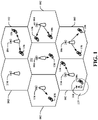
- FIG. 1 is a diagram illustrating a generalized example of a network 100.
- the network 100 is divided into a number of cellular regions 102/110.
- channel resources may generally be scheduled, and each entity may be synchronous. That is, each node utilizing the network may coordinate its usage of the resources such that transmissions are only made during the allocated portion of the frame, and the time of each allocated portion is synchronized among the different nodes.
- One node in each cellular region 102/110 acts as a scheduling entity.
- Each scheduling entity 104/108 may be a base station or access point, or a user equipment (UE) 106 in a device-to-device (D2D) and/or mesh network.
- the scheduling entity 104/108 manages the resources on the carrier and assigns resources to other users of the channel, including subordinate entities, such as one or more UEs 106 in the cellular network 100.
- the scheduling entities 104 are responsible for all radio related functions including radio bearer control, admission control, mobility control, scheduling, security, and connectivity to a centralized controller and/or gateway. There is no centralized controller in this example of a network 100, but a centralized controller may be used in alternative configurations.
- One or more lower power class scheduling entities 108 may have a cellular region 110 that overlaps with one or more other cellular regions (cells) 102.
- the lower power class scheduling entity 108 may be a femto cell (e.g., home scheduling entity), pico cell, micro cell, remote radio head, or in some instances, another UE 106.
- the macro scheduling entities 104 are each assigned to a respective cell 102 and are configured to provide an access point to a core network for all the UEs 106 in the cells 102.
- the modulation and multiple access scheme employed by the network 100 may vary depending on the particular telecommunications standard being deployed.
- OFDM orthogonal frequency division multiplexing
- SC-FDMA single carrier frequency division multiple access
- FDD frequency division duplexing
- 5G Long Term Evolution
- LTE Long Term Evolution
- EV-DO Evolution-Data Optimized
- EV-DO is an air interface standard promulgated by the 3rd Generation Partnership Project 2 (3GPP2) as part of the CDMA2000 family of standards and employs CDMA to provide broadband Internet access to mobile stations.
- 3GPP2 3rd Generation Partnership Project 2
- W-CDMA Wideband-CDMA
- GSM Global System for Mobile Communications
- E-UTRA Evolved UTRA
- Wi-Fi IEEE 802.11
- WiMAX IEEE 802.16
- Flash-OFDM employing OFDMA.
- UTRA, E-UTRA, UMTS, LTE and GSM are described in documents from the 3GPP organization.
- CDMA2000 is described in documents from the 3GPP2 organization.
- the actual wireless communication standard and the multiple access technology employed will depend on the specific application and the overall design constraints imposed on the system.
- the scheduling entities 104 may have multiple antennas supporting MIMO technology.
- MIMO technology enables the scheduling entities 104 to exploit the spatial domain to support spatial multiplexing, beamforming, and transmit diversity.
- Spatial multiplexing may be used to transmit different streams of data simultaneously on the same frequency.
- the data steams may be transmitted to a single UE 106 to increase the data rate or to multiple UEs 106 to increase the overall system capacity. This is achieved by spatially precoding each data stream (i.e., applying a scaling of an amplitude and a phase) and then transmitting each spatially precoded stream through multiple transmit antennas on the downlink (DL).
- DL downlink
- the spatially precoded data streams arrive at the UE(s) 106 with different spatial signatures, which enables each of the UE(s) 106 to recover the one or more data streams destined for that UE 106.
- Beamforming may be used to focus the transmission energy in one or more directions. This may be achieved by spatially precoding the data for transmission through multiple antennas. To achieve good coverage at the edges of the cell, a single stream beamforming transmission may be used in combination with transmit diversity.
- OFDM is a spread-spectrum technique that modulates data over a number of subcarriers within an OFDM symbol.
- the subcarriers are spaced apart at precise frequencies. The spacing provides orthogonality that enables a receiver to recover the data from the subcarriers.
- a guard interval e.g., cyclic prefix
- the UL may use SC-FDMA in the form of a Discrete Fourier Transform (DFT)-spread OFDM signal to compensate for high peak-to-average power ratio (PAPR).
- DFT Discrete Fourier Transform
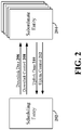
- FIG. 2 a block diagram illustrates an exemplary scheduling entity 202 in wireless communication with a plurality of subordinate entities 204.
- the scheduling entity 202 transmits downlink data channel(s) 206 and downlink control channel(s) 208, while the subordinate entities 204 transmit uplink data channel(s) 210 and uplink control channel(s) 212.
- the channels illustrated in FIG. 1 are not necessarily all of the channels that may be utilized between a scheduling entity 202 and subordinate entities 204, and those of ordinary skill in the art will recognize that other channels may be utilized in addition to those illustrated, such as other data, control, and feedback channels.
- the term downlink may refer to a point-to-multipoint transmission originating at the scheduling entity 202.
- the term uplink may refer to a point-to-point transmission originating at a subordinate entity 204.
- the scheduling entity 202 is a node or device responsible for scheduling traffic in a wireless communication network, including the downlink transmissions and, in some examples, uplink data 210 from one or more subordinate entities 204 to the scheduling entity 202.
- a scheduling entity 102 may be, or may reside within, a base station, a network node, a user equipment (UE), an access terminal, or any suitable node or peer in a wireless communication network.
- UE user equipment
- the subordinate entity 204 is a node or device that receives scheduling control information, including but not limited to scheduling grants, synchronization or timing information, or other control information from another entity in the wireless communication network such as the scheduling entity 202.
- a subordinate entity may be, or may reside within, a base station, a network node, a UE, an access terminal, or any suitable node or peer in a wireless communication network.
- the scheduling entity 202 may transmit downlink data 206 to one or more subordinate entities 204.
- the subordinate entities 204 may transmit uplink data 210 to the scheduling entity 202.
- the uplink data 210 and/or downlink data 206 may be transmitted in transmission time intervals (TTIs).
- TTI refers to the period in which a block of data, corresponding to the smallest collection of symbols to be processed at the Media Access Control (MAC) layer and above, is transferred by the physical layer onto the radio interface.
- MAC Media Access Control
- a TTI is equal to the duration of a subframe.
- subframe refers to an encapsulated set of information sent within a single TTI that is capable of being independently decoded.
- multiple subframes are grouped together to form a single frame.
- the TTI (subframe duration) is set to 1 ms
- the frame duration is set to 10 ms, corresponding to 10 subframes.
- a subframe may have a duration of 250 ⁇ s, 1 ms, or any suitable duration.
- any suitable number of subframes may occupy a frame.
- Frames are generally utilized by upper Open Systems Interconnection (OSI) layers for synchronization and other purposes.
- OSI Open Systems Interconnection
- the scheduling entity 202 may multiplex downlink data for a set of subordinate entities (i.e., two or more subordinate entities) within a single subframe.
- the scheduling entity 202 may multiplex downlink data to the set of subordinate entities using time division multiplexing, frequency division multiplexing (e.g., OFDM), code division multiplexing, and/or any suitable multiplexing scheme known to those of ordinary skill in the art.
- any suitable multiple access scheme may be utilized to combine uplink data from multiple subordinate entities 204 within a single subframe.
- the scheduling entity 202 may further broadcast downlink control channel(s) 208 to one or more subordinate entities 204.
- the downlink control channel(s) 208 may include in some examples a physical downlink control channel (PDCCH), a physical downlink shared channel (PDSCH) and/or any other control channels or pilots, such as the Channel State Information - Reference Signal (CSI-RS) pilot.
- the downlink control channel(s) 208 may include acknowledgement information (e.g., acknowledged (ACK)/not acknowledged (NACK) packets) indicating whether the uplink data 210 in one or more subframes was received correctly at the scheduling entity 202.
- acknowledgement information e.g., acknowledged (ACK)/not acknowledged (NACK) packets
- a data packet may include verification bits, such as a checksum and/or a cyclic redundancy check (CRC).
- CRC cyclic redundancy check
- a device receiving the data packet may receive and decode a data packet and verify the integrity of the received and decoded packet in accordance with the verification bits.
- ACK positive acknowledgment
- NACK negative acknowledgment
- each of the subordinate entities 204 may transmit uplink control channel(s) 212 to the scheduling entity 202.
- the uplink control channel(s) 212 may include in some examples a physical uplink control channel (PUCCH), random access channel (RACH), scheduling request (SR), sounding reference signal (SRS), channel quality indicator (CQI), channel state feedback information, buffer status information, or any other suitable control information or signaling.
- the uplink control channel(s) 212 may include acknowledgement information (e.g., acknowledged (ACK)/not acknowledged (NACK) packets) indicating whether the downlink data 206 in one or more subframes was received correctly at the subordinate entity 204.
- acknowledgement information e.g., acknowledged (ACK)/not acknowledged (NACK) packets
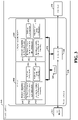
- FIG. 3 is a conceptual diagram illustrating an example of a hardware implementation for a scheduling entity 202 employing a processing system 314.
- a processing system 314 that includes one or more processors 304.
- the scheduling entity 202 may be any suitable radio transceiver apparatus, and in some examples, may be embodied by a base station (BS), a base transceiver station (BTS), a radio base station, a radio transceiver, a transceiver function, a basic service set (BSS), an extended service set (ESS), an access point (AP), a Node B, an eNode B (eNB), mesh node, relay, peer, or some other suitable terminology.
- a base station may be referred to as a scheduling entity, indicating that the base station provides scheduling information to one or more subordinate entities.
- the scheduling entity 202 may be embodied by a wireless user equipment (UE).
- UE wireless user equipment
- a UE include a cellular phone, a smart phone, a session initiation protocol (SIP) phone, a laptop, a notebook, a netbook, a smartbook, a personal digital assistant (PDA), a satellite radio, a global positioning system (GPS) device, a multimedia device, a video device, a digital audio player (e.g., MP3 player), a camera, a game console, an entertainment device, a vehicle component, a wearable computing device (e.g., a smart watch, a health or fitness tracker, etc.), an appliance, a sensor, a vending machine, or any other similar functioning device.
- GPS global positioning system
- the UE may also be referred to by those skilled in the art as a mobile station (MS), a subscriber station, a mobile unit, a subscriber unit, a wireless unit, a remote unit, a mobile device, a wireless device, a wireless communications device, a remote device, a mobile subscriber station, an access terminal (AT), a mobile terminal, a wireless terminal, a remote terminal, a handset, a terminal, a user agent, a mobile client, a client, or some other suitable terminology.
- a UE may be referred to either as a scheduling entity, or a subordinate entity. That is, in various aspects of the present disclosure, a wireless UE may operate as a scheduling entity providing scheduling information to one or more subordinate entities, or may operate as a subordinate entity, operating in accordance with scheduling information provided by a scheduling entity.
- processors 304 include microprocessors, microcontrollers, digital signal processors (DSPs), field programmable gate arrays (FPGAs), programmable logic devices (PLDs), state machines, gated logic, discrete hardware circuits, and other suitable hardware configured to perform the various functionality described throughout this disclosure. That is, the processor 304, as utilized in the scheduling entity 202, may be used to implement any one or more of the processes described below.
- DSPs digital signal processors
- FPGAs field programmable gate arrays
- PLDs programmable logic devices
- state machines gated logic, discrete hardware circuits, and other suitable hardware configured to perform the various functionality described throughout this disclosure. That is, the processor 304, as utilized in the scheduling entity 202, may be used to implement any one or more of the processes described below.
- the processing system 314 may be implemented with a bus architecture, represented generally by the bus 302.
- the bus 302 may include any number of interconnecting buses and bridges depending on the specific application of the processing system 314 and the overall design constraints.
- the bus 302 links together various circuits including one or more processors (represented generally by the processor 304), a memory 305, and computer-readable media (represented generally by the computer-readable medium 306).
- the bus 302 may also link various other circuits such as timing sources, peripherals, voltage regulators, and power management circuits, which are well known in the art, and therefore, will not be described any further.
- a bus interface 308 provides an interface between the bus 302 and a transceiver 310.
- the transceiver 310 provides a means for communicating with various other apparatus over a transmission medium.
- a user interface 312 e.g., keypad, display, touch screen, speaker, microphone, joystick
- a user interface 312 may also be provided.
- the processor 304 is responsible for managing the bus 302 and general processing, including the execution of software stored on the computer-readable medium 306.
- the software when executed by the processor 304, causes the processing system 314 to perform the various functions described below for any particular apparatus.
- the computer-readable medium 306 may also be used for storing data that is manipulated by the processor 304 when executing software.
- the processor 304 may include resource assignment and subframe control circuitry 341, configured to generate, schedule, and modify a resource assignment or grant of time-frequency resources.
- the resource assignment and subframe control circuitry 341 may generate one or more subframes, each including time-frequency resources assigned to carry data and/or control information to and/or from multiple subordinate entities.
- the resource assignment and subframe control circuitry 341 may operate in coordination with resource assignment and subframe control software 351.
- the processor 304 may further include downlink (DL) data and control channel generation and transmission circuitry 342, configured to generate and transmit downlink data and control channels.
- the DL data and control channel generation and transmission circuitry 342 may operate in coordination with the resource assignment and subframe control circuitry 341 to schedule the DL data and/or control information and to place the DL data and/or control information onto a time division duplex (TDD) carrier within one or more subframes generated by the resource assignment and subframe control circuitry 341 in accordance with the resources assigned to the DL data and/or control information.
- TDD time division duplex
- the DL data and control channel generation and transmission circuitry 342 may further operate in coordination with DL data and control channel generation and transmission software 352.
- the processor 304 may further include uplink (UL) data and control channel reception and processing circuitry 343, configured to receive and process uplink control channels and uplink data channels from one or more subordinate entities.
- UL data and control channel reception and processing circuitry 343 may be configured to receive scheduling requests from one or more subordinate entities, the scheduling requests being configured to request a grant of time-frequency resources for uplink user data transmissions.
- the UL data and control channel reception and processing circuitry 343 may be configured to receive and process acknowledgement information (e.g., acknowledged/not acknowledged packets) from one or more subordinate entities.
- the UL data and control channel reception and processing circuitry 343 may operate in coordination with the resource assignment and subframe control circuitry 341 to schedule UL data transmissions, DL data transmissions and/or DL data retransmissions in accordance with the received UL control channel information.
- the UL data and control channel reception and processing circuitry 343 may further operate in coordination with UL data and control channel reception and processing software 353.
- the processor 304 may further include subframe configuration circuitry 344, configured for providing a subframe structure for use by the resource assignment and subframe control circuitry 341 in generating one or more subframes for a TDD carrier.
- the subframe configuration circuitry 344 may be configured to provide a self-contained TDD subframe structure, in which control, data and acknowledgement information are self-contained within a single TDD subframe. That is, the control/scheduling information provides control/scheduling for all of the data packets within the subframe and the acknowledgement information includes acknowledgement/not acknowledgement (ACK/NACK) signals for all of the data packets within the subframe. Therefore, the self-contained subframe structure may contain transmissions in both the uplink and the downlink directions.
- the self-contained TDD subframe structure includes DL control (scheduling) information, DL data information corresponding to the scheduling information and UL acknowledgement information corresponding to the data information.
- the self-contained subframe structure includes DL control (scheduling) information, UL data information corresponding to the scheduling information and DL acknowledgement information corresponding to the data information.
- the subframe structure may be fixed in duration to enable operation in a synchronous network, in which the start of each subframe is aligned across the network.
- the subframe structure duration may be configurable and determined during system deployment and/or updated through system messages.
- the subframe configuration circuitry 344 may operate in coordination with subframe configuration software 354.
- the subframe configuration circuitry 344 may provide a subframe structure for a current subframe by first determining the duration of the current subframe and then determining whether the current subframe should include primarily UL data information or primarily DL data information.
- the subframe configuration circuitry 344 determines that the current subframe should include primarily DL data information
- the subframe configuration circuitry 344 provides a self-contained subframe structure that includes a DL control (scheduling) portion, a DL data portion and an UL acknowledgement portion.
- the subframe configuration circuitry 344 determines that the current subframe should include primarily UL data information
- the subframe configuration circuitry 344 provides a self-contained subframe structure that includes a DL control (scheduling) portion, an UL data portion and a DL acknowledgement portion.
- the subframe configuration circuitry 344 may further provide the subframe structure for the current subframe by determining the switch point times between UL and DL transmissions within the current subframe.
- the subframe structure for the current subframe may include deterministic times within the current subframe to switch from UL transmissions to DL transmissions. For example, when the current subframe includes a DL data portion, the switch point to begin including UL acknowledgement information from the subordinate entities may be predetermined within the subframe.
- the DL data and control channel generation and transmission circuitry 342 may generate the current subframe by preparing control and/or data information in memory 305 and scheduling the control and/or data information via the resource assignment and subframe control circuitry 341 for transmission according to the subframe structure provided by the subframe configuration circuitry 344.
- the DL data and control channel generation and transmission circuitry 342 may further coordinate with the UL data and control reception and processing circuitry 343 to generate the current subframe, as described below.
- the DL data and control channel generation and transmission circuitry 342 may include DL control (scheduling) information in the control portion and DL data information corresponding to the DL control information in the data portion of the subframe.
- the DL data and control channel generation and transmission circuitry 342 may include DL control (scheduling) information by preparing the control (scheduling) information in memory 305 and loading the control (scheduling) information from memory 305 into the DL control portion of the subframe and may further include DL data information by preparing the DL data information in memory 305 and loading DL data information from memory 305 into the DL data portion of the subframe.
- the control (scheduling) information may include control (scheduling) information for new DL data packets and retransmitted DL data packets.
- the DL data and control channel generation and transmission circuitry 342 may further carry hybrid automatic repeat request (HARQ) configuration information within the control (scheduling) information for retransmitted DL data packets by preparing the HARQ configuration information in memory 305 and loading the HARQ configuration information from memory 305 into the DL control portion of the current subframe.
- the UL data and control channel reception and processing circuitry 343 may then include acknowledgement information in the acknowledgement portion of the current subframe by receiving and processing ACK/NACK packets sent from one or more subordinate entities in the current subframe.
- the DL data and control channel generation and transmission circuitry 342 may include DL control (scheduling) information in the control portion of the current subframe by preparing the DL control (scheduling) information in memory 305 and loading the control (scheduling) information from memory 305 into the DL control portion.
- the UL data and control channel reception and processing circuitry 343 may then include UL data information in the data portion of the current subframe by receiving and processing the UL data information sent from one or more subordinate entities.
- the DL data and control channel generation and transmission circuitry 342 may then include acknowledgement information corresponding to the received UL data information by preparing the acknowledgement information (ACK/NACK packets) in memory 305 and loading the ACK/NACK packets from memory 305 into the acknowledgement portion of the current subframe.
- the processor 304 may further include modulation and coding configuration circuitry 347, configured for determining a modulation and coding scheme (MCS) to utilize for downlink transmissions and/or a MCS for a subordinate entity to utilize for uplink transmissions.
- MCS modulation and coding scheme
- the modulation and coding configuration circuitry 347 may operate in coordination with modulation and coding configuration software 357.
- One or more processors 304 in the processing system may execute software.
- Software shall be construed broadly to mean instructions, instruction sets, code, code segments, program code, programs, subprograms, software modules, applications, software applications, software packages, routines, subroutines, objects, executables, threads of execution, procedures, functions, etc., whether referred to as software, firmware, middleware, microcode, hardware description language, or otherwise.
- the software may reside on a computer-readable medium 306.
- the computer-readable medium 306 may be a non-transitory computer-readable medium.
- a non-transitory computer-readable medium includes, by way of example, a magnetic storage device (e.g., hard disk, floppy disk, magnetic strip), an optical disk (e.g., a compact disc (CD) or a digital versatile disc (DVD)), a smart card, a flash memory device (e.g., a card, a stick, or a key drive), a random access memory (RAM), a read only memory (ROM), a programmable ROM (PROM), an erasable PROM (EPROM), an electrically erasable PROM (EEPROM), a register, a removable disk, and any other suitable medium for storing software and/or instructions that may be accessed and read by a computer.
- a magnetic storage device e.g., hard disk, floppy disk, magnetic strip
- an optical disk e.g., a compact disc (CD) or a digital versatile disc (DVD)
- a smart card e.g., a flash memory device (e.g.
- the computer-readable medium may also include, by way of example, a carrier wave, a transmission line, and any other suitable medium for transmitting software and/or instructions that may be accessed and read by a computer.
- the computer-readable medium 306 may reside in the processing system 314, external to the processing system 314, or distributed across multiple entities including the processing system 314.
- the computer-readable medium 306 may be embodied in a computer program product.
- a computer program product may include a computer-readable medium in packaging materials.
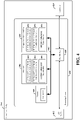
- FIG. 4 is a conceptual diagram illustrating an example of a hardware implementation for an exemplary subordinate entity 204 employing a processing system 414.
- an element, or any portion of an element, or any combination of elements may be implemented with a processing system 414 that includes one or more processors 404.
- the processing system 414 may be substantially the same as the processing system 314 illustrated in FIG. 3 , including a bus interface 408, a bus 402, memory 405, a processor 404, and a computer-readable medium 406. Furthermore, the subordinate entity 204 may include a user interface 412 and a transceiver 410 substantially similar to those described above in FIG. 3 .
- the processor 404 as utilized in a subordinate entity 204, may be used to implement any one or more of the processes described below.
- the processor 404 may include uplink (UL) data and control channel generation and transmission circuitry 442, configured to generate and transmit uplink data on an UL data channel, and to generate and transmit uplink control/feedback/acknowledgement information on an UL control channel.
- the UL data and control channel generation and transmission circuitry 442 may operate in coordination with UL data and control channel generation and transmission software 452.
- the processor 404 may further include downlink (DL) data and control channel reception and processing circuitry 444, configured for receiving and processing downlink data on a data channel, and to receive and process control information on one or more downlink control channels.
- received downlink data and/or control information may be temporarily stored in a data buffer within memory 405.
- the DL data and control channel generation and transmission circuitry 444 may operate in coordination with DL data and control channel generation and transmission software 454.
- the processor 404 may further include subframe configuration determination circuitry 446, configured for determining a subframe structure and subframe duration for one or more subframes. For example, the subframe structure for a current subfame may be determined based on structure information received from the scheduling entity in the DL control portion of a previous subframe.
- the subframe configuration determination circuitry 446 may operate in coordination with the suframe configuration determination software 456.
- the subframe configuration determination circuitry may provide a subframe structure for a current subframe by determining the subframe structure identified by the scheduling entity (e.g., based on subframe structure information received in the DL control portion of a previous subframe). Based on the subframe structure for the current subframe, as determined by the subframe configuration determination circuitry 446, the UL data and control channel generation and transmission circuitry 442 may prepare control and/or data information in memory 405 for transmission according to the subframe structure.
- the DL data and control channel reception and processing circuitry 444 may receive and process DL control information included in the control portion of the current subframe from the scheduling entity and DL data information included in the data portion of the current subfame from the scheduling entity.
- the UL data and control channel generation and transmission circuitry 442 may then include acknowledgement information corresponding to the received UL data information by preparing the acknowledgement information (ACK/NACK packets) in memory 405 and loading the ACK/NACK packets from memory 405 into the acknowledgement portion of the current subframe.
- the DL data and control channel reception and processing circuitry 444 may receive and process DL control information included in the control portion of the subframe.
- the UL data and control channel generation and transmission circuitry 442 may then include UL control and/or data information in the data portion of the current subframe by preparing the UL control and/or data information in memory 405 and loading the UL control and/or data information from memory 405 into the data portion of the current subframe.
- the DL data and control channel reception and processing circuitry 444 may then receive and process acknowledgement information (ACK/NACK packets) corresponding to the transmitted UL data packets in the acknowledgement portion of the current subframe.
- ACK/NACK packets acknowledgement information
- FIG. 5 illustrates an exemplary structure of a self-contained TDD subframe 500.
- the self-contained subframe 500 may have a fixed duration (t), but may also be configurable and determined during network deployment and/or may be updated through system messages.
- the duration of the self-contained subframe 500 may be 500 ⁇ s.
- any suitable subframe duration may be utilized within the scope of the present disclosure.
- the self-contained subframe structure shown in FIG. 5 is a transmitter-scheduled subframe, referred to herein as a downlink TTI subframe or DL-centric subframe 500.
- the DL-centric subframe 500 may be used to carry control and data information to one or more subordinate entities, which may be UEs for example, and to also receive acknowledgement information from the subordinate entity or entities within the same subframe.
- each DL-centric subframe includes both DL transmissions and UL transmissions and is divided with respect to time (t) into DL transmission and UL transmission portions.
- the DL transmission portions include a control portion 502 and a data portion 504, and the UL transmission portions include an acknowledgement (ACK/NACK) portion 508. Therefore, within the subframe structure of FIG. 5 , the scheduling entity first has an opportunity to transmit control/scheduling information in the control portion 502, and then an opportunity to transmit data in the DL data portion 504. Following a guard period (GP) portion 506, the scheduling entity has an opportunity to receive acknowledged (ACK)/not acknowledged (NACK) signals (ACK/NACK packets) from subordinate entities using the carrier.
- This frame structure is downlink-centric, as more resources are allocated for transmissions in the downlink direction (e.g., transmissions from the scheduling entity) than for transmissions in the uplink direction (e.g., transmissions from the subordinate entities).
- control information portion 502 may be used to transmit a physical downlink control channel (PDCCH) indicating time-frequency assignments of data packets intended for one or more subordinate entities
- DL data portion 504 may be used to transmit a data payload including the data packets intended for the one or more subordinate entities within the assigned time-frequency slots.
- PDCCH physical downlink control channel
- each subordinate entity that will be receiving data in the data portion 504 of the subframe 500 may be individually addressed in the control portion 502 of the subframe 500, so that the subordinate entities can receive and process the correct downlink data packets.
- all of the data packets transmitted within the subframe 500 may be scheduled according to the scheduling information in the control information portion 502 of the same subframe 500.
- the scheduling entity may receive an ACK signal (or a NACK signal) during the ACK/NACK portion 508 from each subordinate entity that received data packets during the data portion 504 to indicate whether the data packets were successfully received.
- the scheduling entity may receive an ACK signal (or a NACK signal) during the ACK/NACK portion 508 from each subordinate entity that received data packets during the data portion 504 to indicate whether the data packets were successfully received.
- all of the data packets transmitted within the subframe 500 may be acknowledged/not acknowledged within the same subframe 500.
- control portion 502 may be used to transmit other downlink control channels and/or other downlink pilots, such as the channel state information - reference signal (CSI-RS). These additional downlink channels and/or pilots, along with any other downlink control information, may be transmitted together with the PDCCH within the control portion 502. Broadly, any suitable transmission in the DL direction may be made complementary to the control information described above within the control portion 502.
- the ACK/NACK portion 508 may also be used for transmission of other uplink control channels and information, such as the physical uplink control channel (PUCCH), random access channel (RACH), scheduling request (SR), sounding reference signal (SRS), channel quality indicator (CQI), channel state feedback information and buffer status.
- PUCCH physical uplink control channel
- RACH random access channel
- SR scheduling request
- SRS sounding reference signal
- CQI channel quality indicator
- channel state feedback information and buffer status any suitable transmission in the UL direction may be made complementary to the ACK/NACK and other information described above within the ACK/NACK
- the data portion 504 may be used to multiplex DL data transmissions to a set of subordinate entities (i.e., two or more subordinate entities) within the subframe 500.
- the scheduling entity may multiplex downlink data to the set of subordinate entities using time division multiplexing (TDM), frequency division multiplexing (FDM) (i.e., OFDM), code division multiplexing (CDM), and/or any suitable multiplexing scheme known to those of ordinary skill in the art.
- TDM time division multiplexing
- FDM frequency division multiplexing
- CDM code division multiplexing
- the DL data portion 504 may include data for multiple users and up to a high order of multi-user MIMO.
- the control portion 502 and ACK/NACK portion 508 may also be used to multiplex control information to or from a set of subordinate entities in a TDM, FDM, CDM, and/or other suitable manner.
- the GP portion 506 may be scheduled to accommodate variability in UL and DL timing. For example, latencies due to RF antenna direction switching (e.g., from DL to UL) and RF settling (e.g., settling of phase lock loops, filters and power amplifiers), along with transmission path latencies, may cause the subordinate entity to transmit early on the UL to match DL timing. Such early transmission may interfere with symbols received from the scheduling entity. Accordingly, the GP portion 506 may allow an amount of time after the DL data portion 504 to prevent interference, where the GP portion 506 may provide an appropriate amount of time for the scheduling entity to switch its RF antenna direction, for the over-the-air (OTA) transmission time, and time for ACK processing by the subordinate entity. The GP portion 506 may further provide an appropriate amount of time for the subordinate entity to switch its RF antenna direction (e.g., from DL to UL), to processes the data payload, and for the over-the-air (OTA) transmission time.
- OTA over
- the duration of the GP portion 506 may be configurable based on, for example, the cell size and/or processing time requirements.
- the GP portion 506 may have a duration of one symbol period (e.g., 31.25 ⁇ s).
- the switch point from DL to UL transmissions may be deterministic throughout the network.
- the beginning point of the GP portion 506 may be variable and configurable, the ending point of the GP portion 506 corresponding to the switch point from DL transmissions to UL transmissions may be fixed by the network to manage interference between DL and UL transmissions.
- the switch point may be updated by the network in a semi-static manner and indicated in the PDCCH.
- the GP duration and/or beginning point of the GP portion 506 may also be indicated in the PDCCH.
- the switch point may be maintained at a deterministic location, common to different cells.
- the data portion 504 of the subframe 500 can be filled by either extending the transmission to occupy only a portion of the frequency band or filling in the transmission with pilots or other filler symbols.
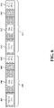
- FIG. 6 illustrates two contiguous DL-centric subframes 601 and 603.
- Each subframe 601 and 603 has the same subframe structure as that shown in FIG. 5 .
- subframe 601 includes a DL control portion 602 followed by a DL data portion 604, a guard period (GP) 606 and an UL ACK/NACK portion 608.
- subframe 603 includes a DL control portion 610, DL data portion 612, GP 614 and UL ACK/NACK portion 616.
- control information may be transmitted by the scheduling entity in the control portion 602 of the first DL-centric subframe 601
- data information corresponding to the control information may be transmitted by the scheduling entity in the data portion 604 of the first DL-centric subframe 601
- acknowledgement information corresponding to the data information may be received by the scheduling entity from subordinate entities in the ACK/NACK portion 608 of the first DL-centric subframe 601.
- all of the data packets in the data portion 604 may be acknowledged or not within the ACK/NACK portion 608, that is, prior to the next scheduling instance.
- the next scheduling instance refers to the scheduling of further data packets within the data portion 612 of the subsequent subframe 603, which are to be scheduled in the control portion 610 of the subframe 603.
- the scheduling entity may generate control information for the control portion 610 of the next (second) DL-centric subframe 603. For example, if the ACK/NACK information includes a NACK signal, at least part of the coded bits of the data information transmitted in the data portion 604 of the first DL-centric subframe 601 may be retransmitted (e.g., in an incremental redundancy HARQ algorithm, described further below) in the data portion 612 of the second DL-centric subframe 603.
- all of the data packets transmitted in the first DL-centric subframe 601 are acknowledged/not acknowledged prior to the next (second) DL-centric subframe 603 to enable the scheduling entity to generate control information for the second DL-centric subframe 603 based on the ACK/NACK information in the first DL-centric subframe 601.
- a hybrid automatic repeat request (HARQ) retransmission scheme is used to retransmit data incorrectly received.
- the control information (PDCCH) in the control portion 610 of the second DL-centric subframe 603 may further carry HARQ-related configuration information, such as HARQ identifiers, redundancy version, etc., to provide support for data retransmissions occurring in the data portion 612 of the second DL-centric subframe 603.
- the control information may be configured to indicate whether or not a data packet included in the data portion is a HARQ retransmission.
- the self-contained subframe structure shown in FIG. 6 supports single HARQ interlace processing at the physical layer to enable high data rates in extreme bandwidth cases with a reasonable HARQ buffer cost. By reducing or minimizing the ACK and retransmission latency at the physical layer, the self-contained subframe structure further reduces or minimizes the overall end-to-end latency.
- FIG. 7 illustrates another exemplary structure of a self-contained TDD subframe 700.
- the self-contained subframe structure shown in FIG. 7 is a receiver-scheduled subframe, referred to herein as an uplink TTI subframe or UL-centric subframe 700.
- the UL-centric subframe 700 may be used to receive downlink control information from the scheduling entity, transmit uplink data to a scheduling entity, and receive a downlink ACK/NACK signal for the transmitted data from the scheduling entity.
- each UL-centric subframe 700 also includes both DL transmissions and UL transmissions and is divided with respect to time (t) into DL transmission and UL transmission portions.
- the DL transmission portions include a control portion 702 and an acknowledgement portion 708, and the UL transmission portions include a data portion 706. Therefore, within the UL-centric subframe structure shown in FIG. 7 , the subordinate entity first has an opportunity to receive control information in the control portion 702. Following a GP portion 704, the subordinate entity has an opportunity to transmit data in the UL data portion 706 and to receive acknowledgement information (e.g., an ACK/NACK signal) in the ACK/NACK portion 708.
- This frame structure is uplink-centric, as more resources are allocated for transmissions in the uplink direction (e.g., transmissions from the subordinate entity) than in the downlink direction (e.g., transmissions from the scheduling entity).
- control information portion 702 may be used to transmit a physical downlink control channel (PDCCH) indicating time-frequency assignments of data packets to be transmitted by one or more subordinate entities and the data portion 706 may be used to by the subordinate entities to transmit their data packets to the scheduling entity within the assigned time-frequency slots.
- PDCCH physical downlink control channel
- Each subordinate entity that transmitted data within the data portion 706 may then receive an ACK signal (or a NACK signal) during the ACK/NACK portion 708 from the scheduling entity to indicate whether the data packets were successfully received at the scheduling entity.
- all of the data packets transmitted within the subframe 700 may be acknowledged/not acknowledged within the same subframe 700.
- control portion 702 and/or ACK/NACK portion 708 may be used to transmit other downlink control channels and information and/or data from other layers.
- data portion 706 may also be used to transmit uplink control channels and information.
- control portion 702 of a subframe 700 may carry a data transmission (e.g., a small payload of data) for a subordinate entity, such as an application layer (or layer other than the physical layer) ACK from a previous subframe. The subordinate entity may then acknowledge the data transmission in the data portion 706 of the same subframe 700.
- a data transmission e.g., a small payload of data
- a subordinate entity such as an application layer (or layer other than the physical layer) ACK from a previous subframe.
- the subordinate entity may then acknowledge the data transmission in the data portion 706 of the same subframe 700.
- the UL data portion 706 may be used to carry data transmissions from a set of subordinate entities (i.e., two or more subordinate entities) within the subframe 500 using one or more TDMA, FDMA, CDMA, or any other suitable multiple access scheme.
- the UL data portion 706 may include packets from multiple users and up to a high order of multi-user MIMO.
- the control portion 702 and ACK/NACK portion 708 may also be used to carry control information to a set of subordinate entities in a TDMA, FDMA, CDMA, or other suitable multiple access manner.
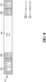
- FIG. 8 illustrates another exemplary structure of a self-contained TDD subframe 800.
- an UL-centric subframe 800 may include two GP portions 804 and 808.
- Each GP portion 804 and 808 separates UL transmissions from DL transmissions to provide an appropriate amount of time for the scheduling and subordinate entities to switch their RF antenna directions. Therefore, within the UL-centric subframe structure shown in FIG. 8 , the subordinate entity first has an opportunity to receive control information in the control portion 802. Following a first GP portion 804, the subordinate entity has an opportunity to transmit data in the UL data portion 806. Following a second GP portion 808, the subordinate entity subsequently has an opportunity to receive an ACK/NACK signal in the ACK/NACK portion 810 from the scheduling entity using the TDD carrier.
- each GP portion 804 and 808 may be configurable based on, for example, the cell size and/or processing time requirements.
- the combined duration of the GP portions 804 and 808 is substantially equivalent to the duration of the single GP portion 704, shown in FIG. 7 .
- the duration of GP portion 804 may be equivalent to or different from the duration of GP portion 808.
- the switch points from DL to UL and from UL to DL transmissions may be deterministic throughout the network.
- each GP portion 804 and 808 may be variable and configurable
- the ending point of each GP portion 804 and 808 corresponding to the switch point between DL/UL transmissions may be fixed by the network to manage interference between DL and UL transmissions.
- FIG. 9 illustrates an example of a consecutive sequence 900 of TDD self-contained subframes 902, 904, 906, 908 and 910, each having a TDD self-contained subframe structure.
- the first three subframes 902, 904 and 906 are DL-centric subframes, each having, for example, the subframe structure shown in FIG. 5 .
- an UL-centric subframe 908, which may have, for example, the subframe structure shown in FIG. 7 or FIG. 8 .
- An additional DL-centric subframe 910 follows the UL-centric subframe.
- the sequence 900 contains more DL-centric subframes than UL-centric subframes to provide sufficient resources to obtain high data rates for downlink data transmission applications.
- UL-centric and DL-centric subframes may alternate or a greater number of UL-centric subframes may be provided in a particular sequence of subframes.
- subframes may accordingly be considered as discrete units.
- the channel can easily be modified to pause or end communication utilizing the TDD carrier, and interpose other communication on the same spectrum resources, without causing substantial issues, e.g., in terms of having data packets waiting for ACK/NACK packets corresponding to data packets transmitted in previous subframes.
- a gap between subframe transmissions may be created to allow multiplexing of different types of traffic on the spectrum, including D2D, mesh, or a non-backward compatible technology.
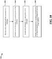
- FIG. 10 is a flow chart 1000 of a method of wireless communication. The method may be performed by a scheduling entity 202 as described above and illustrated in FIG. 2 , by a processor or processing system, or by any suitable means for carrying out the described functions.
- the scheduling entity may provide a self-contained subframe structure for a TDD carrier, including a control portion, a data portion and an acknowledgement portion.
- the self-contained subframe structure may be a DL-centric subframe or an UL-centric subframe, in which the control information, data information corresponding to the control information and acknowledgement information corresponded to the data information are included within a single TDD subframe.
- the scheduling entity generates a subframe having the self-contained subframe structure and includes control information in the control portion of the subframe.
- the control information may include a PDCCH indicating the time-frequency resource assignments for data transmissions from the scheduling entity to a set of subordinate entities.
- the control information may include a PDCCH indicating the time-frequency resource assignments for data transmissions from the set of subordinate entities to the scheduling entity.
- other downlink control information may also be included within the control portion.
- data information corresponding to the control information is included in the data portion of the subframe.
- the data information may include data packets transmitted to the set of subordinate entities multiplexed onto a downlink data channel.
- the data information may include data packets transmitted from the set of subordinate entities combined onto an uplink data channel utilizing a multiple access scheme.
- acknowledgement information corresponding to the data information is included in the acknowledgement portion of the subframe.
- an ACK/NACK message from each subordinate entity that received data in the data portion of the subframe may be included in the acknowledgement portion of the subframe to indicate whether the subordinate entities correctly received the downlink data.
- the acknowledgement information may include respective ACK/NACK messages to each of the subordinate entities that transmitted data in the data portion of the subframe to indicate whether the scheduling entity correctly received the uplink data.
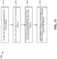
- FIG. 11 is a flow chart 1100 of a method of wireless communication. The method may be performed by a subordinate entity 204 as described above and illustrated in FIG. 2 , by a processor or processing system, or by any suitable means for carrying out the described functions.
- the subordinate entity may provide a self-contained subframe structure for a current subframe, including a control portion, a data portion and an acknowledgement portion.
- the self-contained subframe structure may be a DL-centric subframe or an UL-centric subframe, in which the control information, data information corresponding to the control information and acknowledgement information corresponded to the data information are included within a single TDD subframe.
- the subordinate entity receives control information in the control portion of the subframe.
- the control information may include a PDCCH indicating the time-frequency resource assignments for data transmissions from the scheduling entity to the subordinate entity.
- the control information may include a PDCCH indicating the time-frequency resource assignments for data transmissions from the subordinate entity to the scheduling entity.
- other downlink control information may also be included within the control portion.
- data information corresponding to the control information is included in the data portion of the subframe.
- the data information may include data packets transmitted to the subordinate entity on a downlink data channel.
- the data information may include data packets transmitted from the subordinate entity on an uplink data channel.
- acknowledgement information corresponding to the data information is included in the acknowledgement portion of the subframe.
- an ACK/NACK message from the subordinate entity may be included in the acknowledgement portion of the subframe to indicate whether the subordinate entity correctly received the downlink data.
- the acknowledgement information may include an ACK/NACK message to the subordinate entity o indicate whether the scheduling entity correctly received the uplink data.
- LTE Long Term Evolution
- LTE-A LTE-Advanced
- CDMA2000 Evolution-Data Optimized
- UMB Ultra Mobile Broadband
- IEEE 802.11 Wi-Fi
- IEEE 802.16 WiMAX
- IEEE 802.20 Ultra-Wideband
- Bluetooth Bluetooth
- telecommunication standard, network architecture, and/or communication standard employed will depend on the specific application and the overall design constraints imposed on the system.
- the word "exemplary” is used to mean “serving as an example, instance, or illustration.” Any implementation or aspect described herein as “exemplary” is not necessarily to be construed as preferred or advantageous over other aspects of the disclosure. Likewise, the term “aspects” does not require that all aspects of the disclosure include the discussed feature, advantage or mode of operation.
- the term “coupled” is used herein to refer to the direct or indirect coupling between two objects. For example, if object A physically touches object B, and object B touches object C, then objects A and C may still be considered coupled to one another-even if they do not directly physically touch each other. For instance, a first die may be coupled to a second die in a package even though the first die is never directly physically in contact with the second die.
- circuit and circuitry are used broadly, and intended to include both hardware implementations of electrical devices and conductors that, when connected and configured, enable the performance of the functions described in the present disclosure, without limitation as to the type of electronic circuits, as well as software implementations of information and instructions that, when executed by a processor, enable the performance of the functions described in the present disclosure.
- FIGs. 1-10 One or more of the components, steps, features and/or functions illustrated in FIGs. 1-10 may be rearranged and/or combined into a single component, step, feature or function or embodied in several components, steps, or functions. Additional elements, components, steps, and/or functions may also be added without departing from novel features disclosed herein.
- the apparatus, devices, and/or components illustrated in FIGs. 1-10 may be configured to perform one or more of the methods, features, or steps described herein.
- the novel algorithms described herein may also be efficiently implemented in software and/or embedded in hardware.
Landscapes
- Engineering & Computer Science (AREA)
- Signal Processing (AREA)
- Computer Networks & Wireless Communication (AREA)
- Mobile Radio Communication Systems (AREA)
- Time-Division Multiplex Systems (AREA)
- Bidirectional Digital Transmission (AREA)
Description
- Aspects of the present disclosure relate generally to wireless communication systems, and more particularly, to a self-contained subframe structure for wireless communication utilizing a time division duplex (TDD) carrier.
- Wireless communication networks are widely deployed to provide various communication services such as telephony, video, data, messaging, broadcasts, and so on. Such networks, which are usually multiple access networks, support communications for multiple users by sharing the available network resources.
- The spectrum allocated to such wireless communication networks can include licensed and/or unlicensed spectrum. Licensed spectrum is generally restricted in its use for wireless communication except for licensed use as regulated by a governmental body or other authority within a given region. Unlicensed spectrum is generally free to use, within limits, without the purchase or use of such a license. As the use of wireless communication systems continues to increase, the demand for reallocation of additional spectrum has also increased in many different use cases, including but not limited to telephones, smart phones, PCs, smart meters, remote sensors, smart alarms, mesh nodes, etc.
- In many cases, this spectrum is being (or is expected to be) allocated in such a way that paired carriers, utilized in many existing frequency division duplex (FDD) systems, are either not available, or not available in matched bandwidth configurations. Accordingly, time division duplex (TDD) carriers are expected to be utilized in many future deployments for wireless communication systems.
- The patent document
US 2013/0242904 A1, 19.09.2013 , discloses a method for UE-specific search space and ePDCCH scrambling. - Aspects of the invention are defined in the claims.
- In the following, each of the described methods, apparatuses, examples and aspects which does not fully correspond to the invention as defined in the claims is thus not according to the invention and is, as well as the whole following description, present for illustration purposes only or to highlight specific aspects or features of the claims.
-
-
FIG. 1 is a diagram illustrating an example of a network architecture. -
FIG. 2 is a block diagram conceptually illustrating an example of a scheduling entity communicating with one or more subordinate entities according to some embodiments. -
FIG. 3 is a block diagram illustrating an example of a hardware implementation for a scheduling entity employing a processing system according to some embodiments. -
FIG. 4 is a block diagram illustrating an example of a hardware implementation for a subordinate entity employing a processing system according to some embodiments. -
FIG. 5 is a diagram illustrating an example of a time division duplex (TDD) self-contained subframe structure that may be used in some networks. -
FIG. 6 is a diagram illustrating contiguous TDD subframes, each having a TDD self-contained subframe structure that may be used in some networks. -
FIG. 7 is a diagram illustrating an example of a TDD self-contained subframe structure that may be used in some networks. -
FIG. 8 is a diagram illustrating an example of a TDD self-contained subframe structure that may be used in some networks. -
FIG. 9 is a diagram illustrating an example of a sequence of TDD subframes, each having a TDD self-contained subframe structure that may be used in some networks. -
FIG. 10 is a flow chart of a method of wireless communication. -
FIG. 11 is a flow chart of a method of wireless communication. - The detailed description set forth below in connection with the appended drawings is intended as a description of various configurations and is not intended to represent the only configurations in which the concepts described herein may be practiced. The detailed description includes specific details for the purpose of providing a thorough understanding of various concepts. However, it will be apparent to those skilled in the art that these concepts may be practiced without these specific details. In some instances, well known structures and components are shown in block diagram form in order to avoid obscuring such concepts.
- The various concepts presented throughout this disclosure may be implemented across a broad variety of telecommunication systems, network architectures, and communication standards. In order to illustrate some of the entities or devices described throughout the present disclosure,
FIG. 1 is a diagram illustrating a generalized example of a network 100. In this example, the network 100 is divided into a number ofcellular regions 102/110. In the context of a multiple access network, channel resources may generally be scheduled, and each entity may be synchronous. That is, each node utilizing the network may coordinate its usage of the resources such that transmissions are only made during the allocated portion of the frame, and the time of each allocated portion is synchronized among the different nodes. One node in eachcellular region 102/110 acts as a scheduling entity. - Each
scheduling entity 104/108 may be a base station or access point, or a user equipment (UE) 106 in a device-to-device (D2D) and/or mesh network. The schedulingentity 104/108 manages the resources on the carrier and assigns resources to other users of the channel, including subordinate entities, such as one or more UEs 106 in the cellular network 100. Thescheduling entities 104 are responsible for all radio related functions including radio bearer control, admission control, mobility control, scheduling, security, and connectivity to a centralized controller and/or gateway. There is no centralized controller in this example of a network 100, but a centralized controller may be used in alternative configurations. - One or more lower power
class scheduling entities 108 may have acellular region 110 that overlaps with one or more other cellular regions (cells) 102. The lower powerclass scheduling entity 108 may be a femto cell (e.g., home scheduling entity), pico cell, micro cell, remote radio head, or in some instances, another UE 106. Themacro scheduling entities 104 are each assigned to arespective cell 102 and are configured to provide an access point to a core network for all theUEs 106 in thecells 102. - The modulation and multiple access scheme employed by the network 100 may vary depending on the particular telecommunications standard being deployed. In some radio access networks, such as those defined in LTE standards, orthogonal frequency division multiplexing (OFDM) is used on the downlink (DL) and single carrier frequency division multiple access (SC-FDMA) is used on the uplink (UL) to support both frequency division duplexing (FDD) and TDD. As those skilled in the art will readily appreciate from the detailed description to follow, the various concepts presented herein are well suited for various applications including telecommunication standards employing other modulation and multiple access techniques. By way of example, these concepts may be employed in 5G, LTE, or Evolution-Data Optimized (EV-DO). EV-DO is an air interface standard promulgated by the 3rd Generation Partnership Project 2 (3GPP2) as part of the CDMA2000 family of standards and employs CDMA to provide broadband Internet access to mobile stations. These concepts may also be extended to Universal Terrestrial Radio Access (UTRA) employing Wideband-CDMA (W-CDMA) and other variants of CDMA, such as TD-SCDMA; Global System for Mobile Communications (GSM) employing TDMA; Evolved UTRA (E-UTRA), IEEE 802.11 (Wi-Fi), IEEE 802.16 (WiMAX), IEEE 802.20, and Flash-OFDM employing OFDMA. UTRA, E-UTRA, UMTS, LTE and GSM are described in documents from the 3GPP organization. CDMA2000 is described in documents from the 3GPP2 organization. The actual wireless communication standard and the multiple access technology employed will depend on the specific application and the overall design constraints imposed on the system.
- The
scheduling entities 104 may have multiple antennas supporting MIMO technology. The use of MIMO technology enables thescheduling entities 104 to exploit the spatial domain to support spatial multiplexing, beamforming, and transmit diversity. Spatial multiplexing may be used to transmit different streams of data simultaneously on the same frequency. The data steams may be transmitted to a single UE 106 to increase the data rate or tomultiple UEs 106 to increase the overall system capacity. This is achieved by spatially precoding each data stream (i.e., applying a scaling of an amplitude and a phase) and then transmitting each spatially precoded stream through multiple transmit antennas on the downlink (DL). The spatially precoded data streams arrive at the UE(s) 106 with different spatial signatures, which enables each of the UE(s) 106 to recover the one or more data streams destined for that UE 106. On the uplink (UL), each UE 106 transmits a spatially precoded data stream, which enables thescheduling entity 104 to identify the source of each spatially precoded data stream. - Spatial multiplexing is generally used when channel conditions are good. When channel conditions are less favorable, beamforming may be used to focus the transmission energy in one or more directions. This may be achieved by spatially precoding the data for transmission through multiple antennas. To achieve good coverage at the edges of the cell, a single stream beamforming transmission may be used in combination with transmit diversity.
- Certain aspects of an access network described herein may relate to a system supporting OFDM on the DL. OFDM is a spread-spectrum technique that modulates data over a number of subcarriers within an OFDM symbol. The subcarriers are spaced apart at precise frequencies. The spacing provides orthogonality that enables a receiver to recover the data from the subcarriers. In the time domain, a guard interval (e.g., cyclic prefix) may be added to each OFDM symbol to combat inter-OFDM-symbol interference. The UL may use SC-FDMA in the form of a Discrete Fourier Transform (DFT)-spread OFDM signal to compensate for high peak-to-average power ratio (PAPR).
- Referring now to
FIG. 2 , a block diagram illustrates anexemplary scheduling entity 202 in wireless communication with a plurality ofsubordinate entities 204. Thescheduling entity 202 transmits downlink data channel(s) 206 and downlink control channel(s) 208, while thesubordinate entities 204 transmit uplink data channel(s) 210 and uplink control channel(s) 212. Of course, the channels illustrated inFIG. 1 are not necessarily all of the channels that may be utilized between ascheduling entity 202 andsubordinate entities 204, and those of ordinary skill in the art will recognize that other channels may be utilized in addition to those illustrated, such as other data, control, and feedback channels. - In accordance with aspects of the present disclosure, the term downlink (DL) may refer to a point-to-multipoint transmission originating at the
scheduling entity 202. In addition, the term uplink (UL) may refer to a point-to-point transmission originating at asubordinate entity 204. - Broadly, the
scheduling entity 202 is a node or device responsible for scheduling traffic in a wireless communication network, including the downlink transmissions and, in some examples,uplink data 210 from one or moresubordinate entities 204 to thescheduling entity 202. Ascheduling entity 102 may be, or may reside within, a base station, a network node, a user equipment (UE), an access terminal, or any suitable node or peer in a wireless communication network. - Broadly, the
subordinate entity 204 is a node or device that receives scheduling control information, including but not limited to scheduling grants, synchronization or timing information, or other control information from another entity in the wireless communication network such as thescheduling entity 202. A subordinate entity may be, or may reside within, a base station, a network node, a UE, an access terminal, or any suitable node or peer in a wireless communication network. - As illustrated in
FIG. 2 , thescheduling entity 202 may transmitdownlink data 206 to one or moresubordinate entities 204. In addition, thesubordinate entities 204 may transmituplink data 210 to thescheduling entity 202. In accordance with aspects of the disclosure, theuplink data 210 and/ordownlink data 206 may be transmitted in transmission time intervals (TTIs). As used herein, the term TTI refers to the period in which a block of data, corresponding to the smallest collection of symbols to be processed at the Media Access Control (MAC) layer and above, is transferred by the physical layer onto the radio interface. In accordance with aspects of the disclosure, a TTI is equal to the duration of a subframe. Thus, as further used herein, the term subframe refers to an encapsulated set of information sent within a single TTI that is capable of being independently decoded. In various aspects, multiple subframes are grouped together to form a single frame. For example, in LTE, the TTI (subframe duration) is set to 1 ms, whereas the frame duration is set to 10 ms, corresponding to 10 subframes. However, within the scope of the present disclosure, a subframe may have a duration of 250 µs, 1 ms, or any suitable duration. Similarly, any suitable number of subframes may occupy a frame. Frames are generally utilized by upper Open Systems Interconnection (OSI) layers for synchronization and other purposes. - In an aspect, the
scheduling entity 202 may multiplex downlink data for a set of subordinate entities (i.e., two or more subordinate entities) within a single subframe. For example, thescheduling entity 202 may multiplex downlink data to the set of subordinate entities using time division multiplexing, frequency division multiplexing (e.g., OFDM), code division multiplexing, and/or any suitable multiplexing scheme known to those of ordinary skill in the art. Likewise, any suitable multiple access scheme may be utilized to combine uplink data from multiplesubordinate entities 204 within a single subframe. - The
scheduling entity 202 may further broadcast downlink control channel(s) 208 to one or moresubordinate entities 204. The downlink control channel(s) 208 may include in some examples a physical downlink control channel (PDCCH), a physical downlink shared channel (PDSCH) and/or any other control channels or pilots, such as the Channel State Information - Reference Signal (CSI-RS) pilot. In still a further example, the downlink control channel(s) 208 may include acknowledgement information (e.g., acknowledged (ACK)/not acknowledged (NACK) packets) indicating whether theuplink data 210 in one or more subframes was received correctly at thescheduling entity 202. For example, a data packet may include verification bits, such as a checksum and/or a cyclic redundancy check (CRC). Accordingly, a device receiving the data packet may receive and decode a data packet and verify the integrity of the received and decoded packet in accordance with the verification bits. When the verification succeeds, a positive acknowledgment (ACK) may be transmitted; whereas when the verification fails, a negative acknowledgment (NACK) may be transmitted. - Furthermore, each of the
subordinate entities 204 may transmit uplink control channel(s) 212 to thescheduling entity 202. The uplink control channel(s) 212 may include in some examples a physical uplink control channel (PUCCH), random access channel (RACH), scheduling request (SR), sounding reference signal (SRS), channel quality indicator (CQI), channel state feedback information, buffer status information, or any other suitable control information or signaling. In still a further example, the uplink control channel(s) 212 may include acknowledgement information (e.g., acknowledged (ACK)/not acknowledged (NACK) packets) indicating whether thedownlink data 206 in one or more subframes was received correctly at thesubordinate entity 204. -
FIG. 3 is a conceptual diagram illustrating an example of a hardware implementation for ascheduling entity 202 employing aprocessing system 314. In accordance with various aspects of the disclosure, an element, or any portion of an element, or any combination of elements may be implemented with aprocessing system 314 that includes one ormore processors 304. - In various aspects of the disclosure, the
scheduling entity 202 may be any suitable radio transceiver apparatus, and in some examples, may be embodied by a base station (BS), a base transceiver station (BTS), a radio base station, a radio transceiver, a transceiver function, a basic service set (BSS), an extended service set (ESS), an access point (AP), a Node B, an eNode B (eNB), mesh node, relay, peer, or some other suitable terminology. Within the present document, a base station may be referred to as a scheduling entity, indicating that the base station provides scheduling information to one or more subordinate entities. - In other examples, the
scheduling entity 202 may be embodied by a wireless user equipment (UE). Examples of a UE include a cellular phone, a smart phone, a session initiation protocol (SIP) phone, a laptop, a notebook, a netbook, a smartbook, a personal digital assistant (PDA), a satellite radio, a global positioning system (GPS) device, a multimedia device, a video device, a digital audio player (e.g., MP3 player), a camera, a game console, an entertainment device, a vehicle component, a wearable computing device (e.g., a smart watch, a health or fitness tracker, etc.), an appliance, a sensor, a vending machine, or any other similar functioning device. The UE may also be referred to by those skilled in the art as a mobile station (MS), a subscriber station, a mobile unit, a subscriber unit, a wireless unit, a remote unit, a mobile device, a wireless device, a wireless communications device, a remote device, a mobile subscriber station, an access terminal (AT), a mobile terminal, a wireless terminal, a remote terminal, a handset, a terminal, a user agent, a mobile client, a client, or some other suitable terminology. Within the present document, a UE may be referred to either as a scheduling entity, or a subordinate entity. That is, in various aspects of the present disclosure, a wireless UE may operate as a scheduling entity providing scheduling information to one or more subordinate entities, or may operate as a subordinate entity, operating in accordance with scheduling information provided by a scheduling entity. - Examples of
processors 304 include microprocessors, microcontrollers, digital signal processors (DSPs), field programmable gate arrays (FPGAs), programmable logic devices (PLDs), state machines, gated logic, discrete hardware circuits, and other suitable hardware configured to perform the various functionality described throughout this disclosure. That is, theprocessor 304, as utilized in thescheduling entity 202, may be used to implement any one or more of the processes described below. - In this example, the
processing system 314 may be implemented with a bus architecture, represented generally by thebus 302. Thebus 302 may include any number of interconnecting buses and bridges depending on the specific application of theprocessing system 314 and the overall design constraints. Thebus 302 links together various circuits including one or more processors (represented generally by the processor 304), amemory 305, and computer-readable media (represented generally by the computer-readable medium 306). Thebus 302 may also link various other circuits such as timing sources, peripherals, voltage regulators, and power management circuits, which are well known in the art, and therefore, will not be described any further. Abus interface 308 provides an interface between thebus 302 and atransceiver 310. Thetransceiver 310 provides a means for communicating with various other apparatus over a transmission medium. Depending upon the nature of the apparatus, a user interface 312 (e.g., keypad, display, touch screen, speaker, microphone, joystick) may also be provided. - The
processor 304 is responsible for managing thebus 302 and general processing, including the execution of software stored on the computer-readable medium 306. The software, when executed by theprocessor 304, causes theprocessing system 314 to perform the various functions described below for any particular apparatus. The computer-readable medium 306 may also be used for storing data that is manipulated by theprocessor 304 when executing software. - In some aspects of the disclosure, the
processor 304 may include resource assignment andsubframe control circuitry 341, configured to generate, schedule, and modify a resource assignment or grant of time-frequency resources. For example, the resource assignment andsubframe control circuitry 341 may generate one or more subframes, each including time-frequency resources assigned to carry data and/or control information to and/or from multiple subordinate entities. The resource assignment andsubframe control circuitry 341 may operate in coordination with resource assignment andsubframe control software 351. - The
processor 304 may further include downlink (DL) data and control channel generation andtransmission circuitry 342, configured to generate and transmit downlink data and control channels. The DL data and control channel generation andtransmission circuitry 342 may operate in coordination with the resource assignment andsubframe control circuitry 341 to schedule the DL data and/or control information and to place the DL data and/or control information onto a time division duplex (TDD) carrier within one or more subframes generated by the resource assignment andsubframe control circuitry 341 in accordance with the resources assigned to the DL data and/or control information. The DL data and control channel generation andtransmission circuitry 342 may further operate in coordination with DL data and control channel generation andtransmission software 352. - The
processor 304 may further include uplink (UL) data and control channel reception andprocessing circuitry 343, configured to receive and process uplink control channels and uplink data channels from one or more subordinate entities. In some examples, the UL data and control channel reception andprocessing circuitry 343 may be configured to receive scheduling requests from one or more subordinate entities, the scheduling requests being configured to request a grant of time-frequency resources for uplink user data transmissions. In other examples, the UL data and control channel reception andprocessing circuitry 343 may be configured to receive and process acknowledgement information (e.g., acknowledged/not acknowledged packets) from one or more subordinate entities. The UL data and control channel reception andprocessing circuitry 343 may operate in coordination with the resource assignment andsubframe control circuitry 341 to schedule UL data transmissions, DL data transmissions and/or DL data retransmissions in accordance with the received UL control channel information. The UL data and control channel reception andprocessing circuitry 343 may further operate in coordination with UL data and control channel reception andprocessing software 353. - The
processor 304 may further includesubframe configuration circuitry 344, configured for providing a subframe structure for use by the resource assignment andsubframe control circuitry 341 in generating one or more subframes for a TDD carrier. In accordance with aspects of the disclosure, thesubframe configuration circuitry 344 may be configured to provide a self-contained TDD subframe structure, in which control, data and acknowledgement information are self-contained within a single TDD subframe. That is, the control/scheduling information provides control/scheduling for all of the data packets within the subframe and the acknowledgement information includes acknowledgement/not acknowledgement (ACK/NACK) signals for all of the data packets within the subframe. Therefore, the self-contained subframe structure may contain transmissions in both the uplink and the downlink directions. - In some examples, the self-contained TDD subframe structure includes DL control (scheduling) information, DL data information corresponding to the scheduling information and UL acknowledgement information corresponding to the data information. In other examples, the self-contained subframe structure includes DL control (scheduling) information, UL data information corresponding to the scheduling information and DL acknowledgement information corresponding to the data information. In an aspect, the subframe structure may be fixed in duration to enable operation in a synchronous network, in which the start of each subframe is aligned across the network. However, in various aspects of the disclosure, the subframe structure duration may be configurable and determined during system deployment and/or updated through system messages. The
subframe configuration circuitry 344 may operate in coordination withsubframe configuration software 354. - In an exemplary operation, the
subframe configuration circuitry 344 may provide a subframe structure for a current subframe by first determining the duration of the current subframe and then determining whether the current subframe should include primarily UL data information or primarily DL data information. When thesubframe configuration circuitry 344 determines that the current subframe should include primarily DL data information, thesubframe configuration circuitry 344 provides a self-contained subframe structure that includes a DL control (scheduling) portion, a DL data portion and an UL acknowledgement portion. When thesubframe configuration circuitry 344 determines that the current subframe should include primarily UL data information, thesubframe configuration circuitry 344 provides a self-contained subframe structure that includes a DL control (scheduling) portion, an UL data portion and a DL acknowledgement portion. Thesubframe configuration circuitry 344 may further provide the subframe structure for the current subframe by determining the switch point times between UL and DL transmissions within the current subframe. In an aspect, the subframe structure for the current subframe may include deterministic times within the current subframe to switch from UL transmissions to DL transmissions. For example, when the current subframe includes a DL data portion, the switch point to begin including UL acknowledgement information from the subordinate entities may be predetermined within the subframe. - Based on the subframe structure for the current subframe, the DL data and control channel generation and
transmission circuitry 342 may generate the current subframe by preparing control and/or data information inmemory 305 and scheduling the control and/or data information via the resource assignment andsubframe control circuitry 341 for transmission according to the subframe structure provided by thesubframe configuration circuitry 344. The DL data and control channel generation andtransmission circuitry 342 may further coordinate with the UL data and control reception andprocessing circuitry 343 to generate the current subframe, as described below. - In an aspect, when the subframe structure includes a DL data portion, the DL data and control channel generation and
transmission circuitry 342 may include DL control (scheduling) information in the control portion and DL data information corresponding to the DL control information in the data portion of the subframe. For example, the DL data and control channel generation andtransmission circuitry 342 may include DL control (scheduling) information by preparing the control (scheduling) information inmemory 305 and loading the control (scheduling) information frommemory 305 into the DL control portion of the subframe and may further include DL data information by preparing the DL data information inmemory 305 and loading DL data information frommemory 305 into the DL data portion of the subframe. The control (scheduling) information may include control (scheduling) information for new DL data packets and retransmitted DL data packets. As an example, the DL data and control channel generation andtransmission circuitry 342 may further carry hybrid automatic repeat request (HARQ) configuration information within the control (scheduling) information for retransmitted DL data packets by preparing the HARQ configuration information inmemory 305 and loading the HARQ configuration information frommemory 305 into the DL control portion of the current subframe. The UL data and control channel reception andprocessing circuitry 343 may then include acknowledgement information in the acknowledgement portion of the current subframe by receiving and processing ACK/NACK packets sent from one or more subordinate entities in the current subframe. - In an aspect in which the subframe structure includes an UL data portion, the DL data and control channel generation and
transmission circuitry 342 may include DL control (scheduling) information in the control portion of the current subframe by preparing the DL control (scheduling) information inmemory 305 and loading the control (scheduling) information frommemory 305 into the DL control portion. The UL data and control channel reception andprocessing circuitry 343 may then include UL data information in the data portion of the current subframe by receiving and processing the UL data information sent from one or more subordinate entities. The DL data and control channel generation andtransmission circuitry 342 may then include acknowledgement information corresponding to the received UL data information by preparing the acknowledgement information (ACK/NACK packets) inmemory 305 and loading the ACK/NACK packets frommemory 305 into the acknowledgement portion of the current subframe. - The
processor 304 may further include modulation and coding configuration circuitry 347, configured for determining a modulation and coding scheme (MCS) to utilize for downlink transmissions and/or a MCS for a subordinate entity to utilize for uplink transmissions. The modulation and coding configuration circuitry 347 may operate in coordination with modulation and coding configuration software 357. - One or
more processors 304 in the processing system may execute software. Software shall be construed broadly to mean instructions, instruction sets, code, code segments, program code, programs, subprograms, software modules, applications, software applications, software packages, routines, subroutines, objects, executables, threads of execution, procedures, functions, etc., whether referred to as software, firmware, middleware, microcode, hardware description language, or otherwise. The software may reside on a computer-readable medium 306. The computer-readable medium 306 may be a non-transitory computer-readable medium. A non-transitory computer-readable medium includes, by way of example, a magnetic storage device (e.g., hard disk, floppy disk, magnetic strip), an optical disk (e.g., a compact disc (CD) or a digital versatile disc (DVD)), a smart card, a flash memory device (e.g., a card, a stick, or a key drive), a random access memory (RAM), a read only memory (ROM), a programmable ROM (PROM), an erasable PROM (EPROM), an electrically erasable PROM (EEPROM), a register, a removable disk, and any other suitable medium for storing software and/or instructions that may be accessed and read by a computer. The computer-readable medium may also include, by way of example, a carrier wave, a transmission line, and any other suitable medium for transmitting software and/or instructions that may be accessed and read by a computer. The computer-readable medium 306 may reside in theprocessing system 314, external to theprocessing system 314, or distributed across multiple entities including theprocessing system 314. The computer-readable medium 306 may be embodied in a computer program product. By way of example, a computer program product may include a computer-readable medium in packaging materials. Those skilled in the art will recognize how best to implement the described functionality presented throughout this disclosure depending on the particular application and the overall design constraints imposed on the overall system. -
FIG. 4 is a conceptual diagram illustrating an example of a hardware implementation for an exemplarysubordinate entity 204 employing aprocessing system 414. In accordance with various aspects of the disclosure, an element, or any portion of an element, or any combination of elements may be implemented with aprocessing system 414 that includes one ormore processors 404. - The
processing system 414 may be substantially the same as theprocessing system 314 illustrated inFIG. 3 , including abus interface 408, abus 402,memory 405, aprocessor 404, and a computer-readable medium 406. Furthermore, thesubordinate entity 204 may include auser interface 412 and atransceiver 410 substantially similar to those described above inFIG. 3 . Theprocessor 404, as utilized in asubordinate entity 204, may be used to implement any one or more of the processes described below. - In some aspects of the disclosure, the
processor 404 may include uplink (UL) data and control channel generation andtransmission circuitry 442, configured to generate and transmit uplink data on an UL data channel, and to generate and transmit uplink control/feedback/acknowledgement information on an UL control channel. The UL data and control channel generation andtransmission circuitry 442 may operate in coordination with UL data and control channel generation andtransmission software 452. Theprocessor 404 may further include downlink (DL) data and control channel reception andprocessing circuitry 444, configured for receiving and processing downlink data on a data channel, and to receive and process control information on one or more downlink control channels. In some examples, received downlink data and/or control information may be temporarily stored in a data buffer withinmemory 405. The DL data and control channel generation andtransmission circuitry 444 may operate in coordination with DL data and control channel generation andtransmission software 454. - The
processor 404 may further include subframeconfiguration determination circuitry 446, configured for determining a subframe structure and subframe duration for one or more subframes. For example, the subframe structure for a current subfame may be determined based on structure information received from the scheduling entity in the DL control portion of a previous subframe. The subframeconfiguration determination circuitry 446 may operate in coordination with the suframeconfiguration determination software 456. - In an exemplary operation, the subframe configuration determination circuitry may provide a subframe structure for a current subframe by determining the subframe structure identified by the scheduling entity (e.g., based on subframe structure information received in the DL control portion of a previous subframe). Based on the subframe structure for the current subframe, as determined by the subframe
configuration determination circuitry 446, the UL data and control channel generation andtransmission circuitry 442 may prepare control and/or data information inmemory 405 for transmission according to the subframe structure. In an aspect, when the subframe structure includes a DL data portion, the DL data and control channel reception andprocessing circuitry 444 may receive and process DL control information included in the control portion of the current subframe from the scheduling entity and DL data information included in the data portion of the current subfame from the scheduling entity. The UL data and control channel generation andtransmission circuitry 442 may then include acknowledgement information corresponding to the received UL data information by preparing the acknowledgement information (ACK/NACK packets) inmemory 405 and loading the ACK/NACK packets frommemory 405 into the acknowledgement portion of the current subframe. - In an aspect in which the subframe structure includes an UL data portion, the DL data and control channel reception and
processing circuitry 444 may receive and process DL control information included in the control portion of the subframe. The UL data and control channel generation andtransmission circuitry 442 may then include UL control and/or data information in the data portion of the current subframe by preparing the UL control and/or data information inmemory 405 and loading the UL control and/or data information frommemory 405 into the data portion of the current subframe. The DL data and control channel reception andprocessing circuitry 444 may then receive and process acknowledgement information (ACK/NACK packets) corresponding to the transmitted UL data packets in the acknowledgement portion of the current subframe. -
FIG. 5 illustrates an exemplary structure of a self-containedTDD subframe 500. The self-containedsubframe 500 may have a fixed duration (t), but may also be configurable and determined during network deployment and/or may be updated through system messages. In one example, the duration of the self-containedsubframe 500 may be 500 µs. Of course, any suitable subframe duration may be utilized within the scope of the present disclosure. - The self-contained subframe structure shown in
FIG. 5 is a transmitter-scheduled subframe, referred to herein as a downlink TTI subframe or DL-centric subframe 500. The DL-centric subframe 500 may be used to carry control and data information to one or more subordinate entities, which may be UEs for example, and to also receive acknowledgement information from the subordinate entity or entities within the same subframe. Thus, each DL-centric subframe includes both DL transmissions and UL transmissions and is divided with respect to time (t) into DL transmission and UL transmission portions. - In the example shown in
FIG. 5 , the DL transmission portions include acontrol portion 502 and adata portion 504, and the UL transmission portions include an acknowledgement (ACK/NACK)portion 508. Therefore, within the subframe structure ofFIG. 5 , the scheduling entity first has an opportunity to transmit control/scheduling information in thecontrol portion 502, and then an opportunity to transmit data in theDL data portion 504. Following a guard period (GP)portion 506, the scheduling entity has an opportunity to receive acknowledged (ACK)/not acknowledged (NACK) signals (ACK/NACK packets) from subordinate entities using the carrier. This frame structure is downlink-centric, as more resources are allocated for transmissions in the downlink direction (e.g., transmissions from the scheduling entity) than for transmissions in the uplink direction (e.g., transmissions from the subordinate entities). - In one example, the
control information portion 502 may be used to transmit a physical downlink control channel (PDCCH) indicating time-frequency assignments of data packets intended for one or more subordinate entities, and theDL data portion 504 may be used to transmit a data payload including the data packets intended for the one or more subordinate entities within the assigned time-frequency slots. Thus, each subordinate entity that will be receiving data in thedata portion 504 of thesubframe 500 may be individually addressed in thecontrol portion 502 of thesubframe 500, so that the subordinate entities can receive and process the correct downlink data packets. Thus, all of the data packets transmitted within thesubframe 500 may be scheduled according to the scheduling information in thecontrol information portion 502 of thesame subframe 500. Following theGP portion 506, the scheduling entity may receive an ACK signal (or a NACK signal) during the ACK/NACK portion 508 from each subordinate entity that received data packets during thedata portion 504 to indicate whether the data packets were successfully received. Thus, all of the data packets transmitted within thesubframe 500 may be acknowledged/not acknowledged within thesame subframe 500. - In other examples, the
control portion 502 may be used to transmit other downlink control channels and/or other downlink pilots, such as the channel state information - reference signal (CSI-RS). These additional downlink channels and/or pilots, along with any other downlink control information, may be transmitted together with the PDCCH within thecontrol portion 502. Broadly, any suitable transmission in the DL direction may be made complementary to the control information described above within thecontrol portion 502. In addition, the ACK/NACK portion 508 may also be used for transmission of other uplink control channels and information, such as the physical uplink control channel (PUCCH), random access channel (RACH), scheduling request (SR), sounding reference signal (SRS), channel quality indicator (CQI), channel state feedback information and buffer status. Broadly, any suitable transmission in the UL direction may be made complementary to the ACK/NACK and other information described above within the ACK/NACK portion 508. - In an aspect, the
data portion 504 may be used to multiplex DL data transmissions to a set of subordinate entities (i.e., two or more subordinate entities) within thesubframe 500. For example, the scheduling entity may multiplex downlink data to the set of subordinate entities using time division multiplexing (TDM), frequency division multiplexing (FDM) (i.e., OFDM), code division multiplexing (CDM), and/or any suitable multiplexing scheme known to those of ordinary skill in the art. Thus, theDL data portion 504 may include data for multiple users and up to a high order of multi-user MIMO. In addition, thecontrol portion 502 and ACK/NACK portion 508 may also be used to multiplex control information to or from a set of subordinate entities in a TDM, FDM, CDM, and/or other suitable manner. - The
GP portion 506 may be scheduled to accommodate variability in UL and DL timing. For example, latencies due to RF antenna direction switching (e.g., from DL to UL) and RF settling (e.g., settling of phase lock loops, filters and power amplifiers), along with transmission path latencies, may cause the subordinate entity to transmit early on the UL to match DL timing. Such early transmission may interfere with symbols received from the scheduling entity. Accordingly, theGP portion 506 may allow an amount of time after theDL data portion 504 to prevent interference, where theGP portion 506 may provide an appropriate amount of time for the scheduling entity to switch its RF antenna direction, for the over-the-air (OTA) transmission time, and time for ACK processing by the subordinate entity. TheGP portion 506 may further provide an appropriate amount of time for the subordinate entity to switch its RF antenna direction (e.g., from DL to UL), to processes the data payload, and for the over-the-air (OTA) transmission time. - The duration of the
GP portion 506 may be configurable based on, for example, the cell size and/or processing time requirements. For example, theGP portion 506 may have a duration of one symbol period (e.g., 31.25 µs). However, in accordance with aspects of the disclosure, the switch point from DL to UL transmissions may be deterministic throughout the network. Thus, although the beginning point of theGP portion 506 may be variable and configurable, the ending point of theGP portion 506 corresponding to the switch point from DL transmissions to UL transmissions may be fixed by the network to manage interference between DL and UL transmissions. In an aspect, the switch point may be updated by the network in a semi-static manner and indicated in the PDCCH. In addition, the GP duration and/or beginning point of theGP portion 506 may also be indicated in the PDCCH. - In networks utilizing unlicensed spectrum, the switch point may be maintained at a deterministic location, common to different cells. In scenarios in which the amount of data to be transmitted is less than that allocated to the
data portion 504, to avoid losing access to the TDD carrier, thedata portion 504 of thesubframe 500 can be filled by either extending the transmission to occupy only a portion of the frequency band or filling in the transmission with pilots or other filler symbols. -
FIG. 6 illustrates two contiguous DL-centric subframes subframe FIG. 5 . For example,subframe 601 includes aDL control portion 602 followed by aDL data portion 604, a guard period (GP) 606 and an UL ACK/NACK portion 608. Likewise,subframe 603 includes aDL control portion 610,DL data portion 612,GP 614 and UL ACK/NACK portion 616. - In an example, control information may be transmitted by the scheduling entity in the
control portion 602 of the first DL-centric subframe 601, data information corresponding to the control information may be transmitted by the scheduling entity in thedata portion 604 of the first DL-centric subframe 601 and acknowledgement information corresponding to the data information may be received by the scheduling entity from subordinate entities in the ACK/NACK portion 608 of the first DL-centric subframe 601. According to an aspect of the present disclosure, all of the data packets in thedata portion 604 may be acknowledged or not within the ACK/NACK portion 608, that is, prior to the next scheduling instance. Here, the next scheduling instance refers to the scheduling of further data packets within thedata portion 612 of thesubsequent subframe 603, which are to be scheduled in thecontrol portion 610 of thesubframe 603. - Based on the ACK/NACK information received in the ACK/
NACK portion 608 of the first DL-centric subframe 601, the scheduling entity may generate control information for thecontrol portion 610 of the next (second) DL-centric subframe 603. For example, if the ACK/NACK information includes a NACK signal, at least part of the coded bits of the data information transmitted in thedata portion 604 of the first DL-centric subframe 601 may be retransmitted (e.g., in an incremental redundancy HARQ algorithm, described further below) in thedata portion 612 of the second DL-centric subframe 603. Thus, in accordance with aspects of the disclosure, all of the data packets transmitted in the first DL-centric subframe 601 are acknowledged/not acknowledged prior to the next (second) DL-centric subframe 603 to enable the scheduling entity to generate control information for the second DL-centric subframe 603 based on the ACK/NACK information in the first DL-centric subframe 601. - In an exemplary aspect of the disclosure, a hybrid automatic repeat request (HARQ) retransmission scheme is used to retransmit data incorrectly received. Thus, the control information (PDCCH) in the
control portion 610 of the second DL-centric subframe 603 may further carry HARQ-related configuration information, such as HARQ identifiers, redundancy version, etc., to provide support for data retransmissions occurring in thedata portion 612 of the second DL-centric subframe 603. For example, the control information may be configured to indicate whether or not a data packet included in the data portion is a HARQ retransmission. - The self-contained subframe structure shown in
FIG. 6 supports single HARQ interlace processing at the physical layer to enable high data rates in extreme bandwidth cases with a reasonable HARQ buffer cost. By reducing or minimizing the ACK and retransmission latency at the physical layer, the self-contained subframe structure further reduces or minimizes the overall end-to-end latency. -
FIG. 7 illustrates another exemplary structure of a self-containedTDD subframe 700. The self-contained subframe structure shown inFIG. 7 is a receiver-scheduled subframe, referred to herein as an uplink TTI subframe or UL-centric subframe 700. The UL-centric subframe 700 may be used to receive downlink control information from the scheduling entity, transmit uplink data to a scheduling entity, and receive a downlink ACK/NACK signal for the transmitted data from the scheduling entity. Thus, each UL-centric subframe 700 also includes both DL transmissions and UL transmissions and is divided with respect to time (t) into DL transmission and UL transmission portions. - In the example shown in
FIG. 7 , the DL transmission portions include acontrol portion 702 and anacknowledgement portion 708, and the UL transmission portions include adata portion 706. Therefore, within the UL-centric subframe structure shown inFIG. 7 , the subordinate entity first has an opportunity to receive control information in thecontrol portion 702. Following aGP portion 704, the subordinate entity has an opportunity to transmit data in theUL data portion 706 and to receive acknowledgement information (e.g., an ACK/NACK signal) in the ACK/NACK portion 708. This frame structure is uplink-centric, as more resources are allocated for transmissions in the uplink direction (e.g., transmissions from the subordinate entity) than in the downlink direction (e.g., transmissions from the scheduling entity). - In one example, the
control information portion 702 may be used to transmit a physical downlink control channel (PDCCH) indicating time-frequency assignments of data packets to be transmitted by one or more subordinate entities and thedata portion 706 may be used to by the subordinate entities to transmit their data packets to the scheduling entity within the assigned time-frequency slots. Each subordinate entity that transmitted data within thedata portion 706 may then receive an ACK signal (or a NACK signal) during the ACK/NACK portion 708 from the scheduling entity to indicate whether the data packets were successfully received at the scheduling entity. Thus, all of the data packets transmitted within thesubframe 700 may be acknowledged/not acknowledged within thesame subframe 700. - In other examples, the
control portion 702 and/or ACK/NACK portion 708 may be used to transmit other downlink control channels and information and/or data from other layers. In addition, thedata portion 706 may also be used to transmit uplink control channels and information. For example, thecontrol portion 702 of asubframe 700 may carry a data transmission (e.g., a small payload of data) for a subordinate entity, such as an application layer (or layer other than the physical layer) ACK from a previous subframe. The subordinate entity may then acknowledge the data transmission in thedata portion 706 of thesame subframe 700. - In an aspect, the
UL data portion 706 may be used to carry data transmissions from a set of subordinate entities (i.e., two or more subordinate entities) within thesubframe 500 using one or more TDMA, FDMA, CDMA, or any other suitable multiple access scheme. Thus, theUL data portion 706 may include packets from multiple users and up to a high order of multi-user MIMO. In addition, thecontrol portion 702 and ACK/NACK portion 708 may also be used to carry control information to a set of subordinate entities in a TDMA, FDMA, CDMA, or other suitable multiple access manner. -
FIG. 8 illustrates another exemplary structure of a self-containedTDD subframe 800. In the example shown inFIG. 8 , an UL-centric subframe 800 may include twoGP portions 804 and 808. EachGP portion 804 and 808 separates UL transmissions from DL transmissions to provide an appropriate amount of time for the scheduling and subordinate entities to switch their RF antenna directions. Therefore, within the UL-centric subframe structure shown inFIG. 8 , the subordinate entity first has an opportunity to receive control information in thecontrol portion 802. Following afirst GP portion 804, the subordinate entity has an opportunity to transmit data in theUL data portion 806. Following a second GP portion 808, the subordinate entity subsequently has an opportunity to receive an ACK/NACK signal in the ACK/NACK portion 810 from the scheduling entity using the TDD carrier. - The duration of each
GP portion 804 and 808 may be configurable based on, for example, the cell size and/or processing time requirements. In an aspect, the combined duration of theGP portions 804 and 808 is substantially equivalent to the duration of thesingle GP portion 704, shown inFIG. 7 . In another aspect, the duration ofGP portion 804 may be equivalent to or different from the duration of GP portion 808. In addition, in accordance with aspects of the disclosure, the switch points from DL to UL and from UL to DL transmissions may be deterministic throughout the network. Thus, although the beginning point of eachGP portion 804 and 808 may be variable and configurable, the ending point of eachGP portion 804 and 808 corresponding to the switch point between DL/UL transmissions may be fixed by the network to manage interference between DL and UL transmissions. -
FIG. 9 illustrates an example of aconsecutive sequence 900 of TDD self-containedsubframes subframes FIG. 5 . Following the third DL-centric subframe 906 is an UL-centric subframe 908, which may have, for example, the subframe structure shown inFIG. 7 orFIG. 8 . An additional DL-centric subframe 910 follows the UL-centric subframe. Thesequence 900 contains more DL-centric subframes than UL-centric subframes to provide sufficient resources to obtain high data rates for downlink data transmission applications. In other examples, UL-centric and DL-centric subframes may alternate or a greater number of UL-centric subframes may be provided in a particular sequence of subframes. - By utilizing a TDD self-contained subframe structure, such as those shown in
FIGs. 5-8 , resources for the transmission of feedback, such as an ACK/NACK, can be made available within the same subframe for all data information transmitted within that subframe. In this way, a device utilizing this subframe structure need not wait for, or depend on, packets in a subsequent subframe. That is, subframes may accordingly be considered as discrete units. - Because the subframes can be considered independent or discrete, additional flexibility in the management of the air interface resources can be provided. For example, at any given time, at the end of any given subframe, the channel can easily be modified to pause or end communication utilizing the TDD carrier, and interpose other communication on the same spectrum resources, without causing substantial issues, e.g., in terms of having data packets waiting for ACK/NACK packets corresponding to data packets transmitted in previous subframes. In one example, a gap between subframe transmissions may be created to allow multiplexing of different types of traffic on the spectrum, including D2D, mesh, or a non-backward compatible technology.
- Of course, these examples of self-contained subframe structures are merely provided to illustrate certain concepts of the invention. Those of ordinary skill in the art will comprehend that these are merely exemplary in nature, and other examples may fall within the scope of the disclosure.
-
FIG. 10 is aflow chart 1000 of a method of wireless communication. The method may be performed by ascheduling entity 202 as described above and illustrated inFIG. 2 , by a processor or processing system, or by any suitable means for carrying out the described functions. - At
block 1002, the scheduling entity may provide a self-contained subframe structure for a TDD carrier, including a control portion, a data portion and an acknowledgement portion. For example, with reference toFIGs. 5-8 , the self-contained subframe structure may be a DL-centric subframe or an UL-centric subframe, in which the control information, data information corresponding to the control information and acknowledgement information corresponded to the data information are included within a single TDD subframe. - At
block 1004, the scheduling entity generates a subframe having the self-contained subframe structure and includes control information in the control portion of the subframe. For a DL-centric subframe, the control information may include a PDCCH indicating the time-frequency resource assignments for data transmissions from the scheduling entity to a set of subordinate entities. For an UL-centric subframe, the control information may include a PDCCH indicating the time-frequency resource assignments for data transmissions from the set of subordinate entities to the scheduling entity. In addition, other downlink control information may also be included within the control portion. - At
block 1006, data information corresponding to the control information is included in the data portion of the subframe. For example, in a DL-centric subframe, the data information may include data packets transmitted to the set of subordinate entities multiplexed onto a downlink data channel. In an UL-centric subframe, the data information may include data packets transmitted from the set of subordinate entities combined onto an uplink data channel utilizing a multiple access scheme. - At
block 1008, acknowledgement information corresponding to the data information is included in the acknowledgement portion of the subframe. For example, in a DL-centric subframe, an ACK/NACK message from each subordinate entity that received data in the data portion of the subframe may be included in the acknowledgement portion of the subframe to indicate whether the subordinate entities correctly received the downlink data. In an UL-centric subframe, the acknowledgement information may include respective ACK/NACK messages to each of the subordinate entities that transmitted data in the data portion of the subframe to indicate whether the scheduling entity correctly received the uplink data. -
FIG. 11 is aflow chart 1100 of a method of wireless communication. The method may be performed by asubordinate entity 204 as described above and illustrated inFIG. 2 , by a processor or processing system, or by any suitable means for carrying out the described functions. - At
block 1102, the subordinate entity may provide a self-contained subframe structure for a current subframe, including a control portion, a data portion and an acknowledgement portion. For example, with reference toFIGs. 5-8 , the self-contained subframe structure may be a DL-centric subframe or an UL-centric subframe, in which the control information, data information corresponding to the control information and acknowledgement information corresponded to the data information are included within a single TDD subframe. - At
block 1104, the subordinate entity receives control information in the control portion of the subframe. For a DL-centric subframe, the control information may include a PDCCH indicating the time-frequency resource assignments for data transmissions from the scheduling entity to the subordinate entity. For an UL-centric subframe, the control information may include a PDCCH indicating the time-frequency resource assignments for data transmissions from the subordinate entity to the scheduling entity. In addition, other downlink control information may also be included within the control portion. - At
block 1106, data information corresponding to the control information is included in the data portion of the subframe. For example, in a DL-centric subframe, the data information may include data packets transmitted to the subordinate entity on a downlink data channel. In an UL-centric subframe, the data information may include data packets transmitted from the subordinate entity on an uplink data channel. - At
block 1108, acknowledgement information corresponding to the data information is included in the acknowledgement portion of the subframe. For example, in a DL-centric subframe, an ACK/NACK message from the subordinate entity may be included in the acknowledgement portion of the subframe to indicate whether the subordinate entity correctly received the downlink data. In an UL-centric subframe, the acknowledgement information may include an ACK/NACK message to the subordinate entity o indicate whether the scheduling entity correctly received the uplink data. - As those skilled in the art will readily appreciate, various aspects described throughout this disclosure may be extended to any suitable telecommunication system, network architecture, and communication standard. By way of example, various aspects may be applied to UMTS systems such as W-CDMA, TD-SCDMA, and TD-CDMA. Various aspects may also be applied to systems employing Long Term Evolution (LTE) (in FDD, TDD, or both modes), LTE-Advanced (LTE-A) (in FDD, TDD, or both modes), CDMA2000, Evolution-Data Optimized (EV-DO), Ultra Mobile Broadband (UMB), IEEE 802.11 (Wi-Fi), IEEE 802.16 (WiMAX), IEEE 802.20, Ultra-Wideband (UWB), Bluetooth, and/or other suitable systems, including those described by yet-to-be defined wide area network standards. The actual telecommunication standard, network architecture, and/or communication standard employed will depend on the specific application and the overall design constraints imposed on the system.
- Within the present disclosure, the word "exemplary" is used to mean "serving as an example, instance, or illustration." Any implementation or aspect described herein as "exemplary" is not necessarily to be construed as preferred or advantageous over other aspects of the disclosure. Likewise, the term "aspects" does not require that all aspects of the disclosure include the discussed feature, advantage or mode of operation. The term "coupled" is used herein to refer to the direct or indirect coupling between two objects. For example, if object A physically touches object B, and object B touches object C, then objects A and C may still be considered coupled to one another-even if they do not directly physically touch each other. For instance, a first die may be coupled to a second die in a package even though the first die is never directly physically in contact with the second die. The terms "circuit" and "circuitry" are used broadly, and intended to include both hardware implementations of electrical devices and conductors that, when connected and configured, enable the performance of the functions described in the present disclosure, without limitation as to the type of electronic circuits, as well as software implementations of information and instructions that, when executed by a processor, enable the performance of the functions described in the present disclosure.
- One or more of the components, steps, features and/or functions illustrated in
FIGs. 1-10 may be rearranged and/or combined into a single component, step, feature or function or embodied in several components, steps, or functions. Additional elements, components, steps, and/or functions may also be added without departing from novel features disclosed herein. The apparatus, devices, and/or components illustrated inFIGs. 1-10 may be configured to perform one or more of the methods, features, or steps described herein. The novel algorithms described herein may also be efficiently implemented in software and/or embedded in hardware. - It is to be understood that the specific order or hierarchy of steps in the methods disclosed is an illustration of exemplary processes. Based upon design preferences, it is understood that the specific order or hierarchy of steps in the methods may be rearranged. The accompanying method claims present elements of the various steps in a sample order, and are not meant to be limited to the specific order or hierarchy presented unless specifically recited therein.
Claims (21)
- A method of wireless communication in a network for a scheduling entity (202) to communicate with a subordinate entity utilizing a time division duplex, TDD, carrier, wherein the TDD carrier comprises a plurality of subframes, the method comprising:transmitting scheduling information in a control portion (502) of a subframe of the plurality of subframes;communicating data information corresponding to the scheduling information in a data portion (504) of the subframe;communicating acknowledgement information corresponding to the data information in an acknowledgement portion (508) of the subframe,wherein the control portion (502), the data portion (504), and the acknowledgement portion (508) are contained in the subframe, the subframe defined via a subframe structure with the control portion (502) and the acknowledgement portion (508) being spaced apart and the data portion (504) being communicated between the control portion (502) and the acknowledgement portion (508).
- The method of claim 1 further comprising communicating a guard period between the data portion of the subframe and the acknowledgement portion of the subframe.
- The method of claim 1, wherein the subframe structure has a configurable subframe duration.
- The method of claim 3, wherein the configurable subframe duration is fixed across the network.
- The method of claim 1, wherein including the acknowledgement information further comprises: beginning the acknowledgement information at a predetermined time in the subframe.
- The method of claim 1, wherein the scheduling entity is a base station and the subordinate entity is a user equipment, the base station being configured to transmit and receive a plurality of the subframes with the user equipment via one or more communication links.
- The method of claim 1, wherein the scheduling entity is configured to communicate with the subordinate entity via a communication link carrying the one or more subframes divided into downlink and uplink transmission portions.
- The method of claim 1, wherein the scheduling entity is configured to communicate with the subordinate entity via a sequence of the plurality of subframes configured for uplink or downlink transmission.
- The method of claim 1, wherein the scheduling entity is configured to communicate with the subordinate entity control information defining communication configuration including a plurality of the subframes.
- The method of claim 2, wherein the guard period has a configurable guard period duration.
- The method of claim 2, wherein the guard period facilitates a switch from one of downlink communications or uplink communications.
- The method of claims 2, 10, or 11, wherein a beginning point of the guard period is configurable and an end point of the guard period corresponds to a switch point from one of downlink communications or uplink communications.
- The method of claim 12, wherein the end point is fixed by the network.
- The method of any preceding claim, wherein the control portion includes a physical downlink control channel, PDCCH.
- The method claim 14, wherein the switch point is updated by the network in a semi-static matter and indicated in the PDCCH.
- The method of claim 15, wherein the configurable guard period duration and/or the beginning point of the guard period is indicated in the PDCCH.
- The method of claim 2, further comprising: including an additional guard period between the data portion of the subframe and the acknowledgement portion of the subframe.
- The method of claim 17, wherein each of the guard period and the additional guard period has a respective configurable guard period duration, the method further comprising: beginning the data portion at a first predetermined time in the subframe; and beginning the acknowledgement portion at a second predetermined time in the subframe.
- A scheduling entity apparatus (202) comprising means for performing the method of any one of claims 1 to 18.
- A method of wireless communication in a network for a subordinate entity (204) to communicate with a scheduling entity utilizing a time division duplex, TDD, carrier, wherein the TDD carrier comprises a plurality of subframes, the method comprising:receiving scheduling information in a control portion (502) of a subframe of the plurality of subframes;communicating data information corresponding to the scheduling information in a data portion (504) of the subframe;communicating acknowledgement information corresponding to the data information in an acknowledgment portion (508) of the subframe,wherein the control portion (502), the data portion (504), and the acknowledgment portion (508) are contained in the subframe, the subframe defined via a subframe structure with the control portion (502) and the acknowledgment portion (508) being spaced apart and the data portion (504) being communicated between the control portion (502) and the acknowledgment portion (508).
- A subordinate entity apparatus (204) comprising means for performing the method of claim 20.
Applications Claiming Priority (5)
| Application Number | Priority Date | Filing Date | Title |
|---|---|---|---|
| US201562133386P | 2015-03-15 | 2015-03-15 | |
| US14/940,546 US10342012B2 (en) | 2015-03-15 | 2015-11-13 | Self-contained time division duplex (TDD) subframe structure |
| EP19193188.0A EP3592079B1 (en) | 2015-03-15 | 2016-02-26 | Self-contained time division duplex (tdd) subframe structure |
| EP16709885.4A EP3272166B1 (en) | 2015-03-15 | 2016-02-26 | Self-contained time division duplex (tdd) subframe structure |
| PCT/US2016/019942 WO2016148878A1 (en) | 2015-03-15 | 2016-02-26 | Self-contained time division duplex (tdd) subframe structure |
Related Parent Applications (2)
| Application Number | Title | Priority Date | Filing Date |
|---|---|---|---|
| EP16709885.4A Division EP3272166B1 (en) | 2015-03-15 | 2016-02-26 | Self-contained time division duplex (tdd) subframe structure |
| EP19193188.0A Division EP3592079B1 (en) | 2015-03-15 | 2016-02-26 | Self-contained time division duplex (tdd) subframe structure |
Publications (2)
| Publication Number | Publication Date |
|---|---|
| EP3879904A1 EP3879904A1 (en) | 2021-09-15 |
| EP3879904B1 true EP3879904B1 (en) | 2022-12-21 |
Family
ID=56888406
Family Applications (3)
| Application Number | Title | Priority Date | Filing Date |
|---|---|---|---|
| EP16709885.4A Active EP3272166B1 (en) | 2015-03-15 | 2016-02-26 | Self-contained time division duplex (tdd) subframe structure |
| EP19193188.0A Active EP3592079B1 (en) | 2015-03-15 | 2016-02-26 | Self-contained time division duplex (tdd) subframe structure |
| EP21169533.3A Active EP3879904B1 (en) | 2015-03-15 | 2016-02-26 | Self-contained time division duplex (tdd) subframe structure |
Family Applications Before (2)
| Application Number | Title | Priority Date | Filing Date |
|---|---|---|---|
| EP16709885.4A Active EP3272166B1 (en) | 2015-03-15 | 2016-02-26 | Self-contained time division duplex (tdd) subframe structure |
| EP19193188.0A Active EP3592079B1 (en) | 2015-03-15 | 2016-02-26 | Self-contained time division duplex (tdd) subframe structure |
Country Status (11)
| Country | Link |
|---|---|
| US (4) | US10342012B2 (en) |
| EP (3) | EP3272166B1 (en) |
| JP (3) | JP6676064B2 (en) |
| KR (3) | KR102076896B1 (en) |
| CN (3) | CN112217612B (en) |
| AU (1) | AU2016233795B2 (en) |
| BR (1) | BR112017019766B1 (en) |
| ES (2) | ES2872279T3 (en) |
| HU (1) | HUE047061T2 (en) |
| TW (2) | TWI723549B (en) |
| WO (1) | WO2016148878A1 (en) |
Families Citing this family (35)
| Publication number | Priority date | Publication date | Assignee | Title |
|---|---|---|---|---|
| US9936519B2 (en) | 2015-03-15 | 2018-04-03 | Qualcomm Incorporated | Self-contained time division duplex (TDD) subframe structure for wireless communications |
| US10342012B2 (en) | 2015-03-15 | 2019-07-02 | Qualcomm Incorporated | Self-contained time division duplex (TDD) subframe structure |
| US10075970B2 (en) | 2015-03-15 | 2018-09-11 | Qualcomm Incorporated | Mission critical data support in self-contained time division duplex (TDD) subframe structure |
| US9814058B2 (en) * | 2015-05-15 | 2017-11-07 | Qualcomm Incorporated | Scaled symbols for a self-contained time division duplex (TDD) subframe structure |
| US10333678B2 (en) | 2015-05-29 | 2019-06-25 | Huawei Technologies Co., Ltd. | Systems and methods of adaptive frame structure for time division duplex |
| US10128993B2 (en) | 2015-05-29 | 2018-11-13 | Huawei Technologies Co., Ltd. | Systems and methods of adaptive frame structure for time division duplex |
| US9992790B2 (en) | 2015-07-20 | 2018-06-05 | Qualcomm Incorporated | Time division duplex (TDD) subframe structure supporting single and multiple interlace modes |
| US20170135078A1 (en) * | 2015-11-10 | 2017-05-11 | Electronics And Telecommunications Research Institute | Method and apparatus for configuring subframe in mobile communication system |
| JP6832937B2 (en) * | 2016-01-19 | 2021-02-24 | ノキア ソリューションズ アンド ネットワークス オサケユキチュア | Guard period between subframe parts of the same link direction in the wireless network |
| US10484989B2 (en) * | 2016-01-22 | 2019-11-19 | Electronics And Telecommunications Research Institute | Method and apparatus for receiving or transmitting data |
| US10404332B2 (en) * | 2016-01-28 | 2019-09-03 | Qualcomm Incorporated | Downlink common burst channelization |
| CN108702754B (en) * | 2016-02-29 | 2023-05-16 | 株式会社Ntt都科摩 | User terminal, radio base station, and radio communication method |
| US10122559B2 (en) | 2016-03-21 | 2018-11-06 | Qualcomm Incorporated | Uplink channel quality measurement using a subframe with high-intensity reference signal bursts |
| EP3444978B1 (en) * | 2016-05-11 | 2020-02-19 | Huawei Technologies Co., Ltd. | Time division duplexing with short transmission time intervals |
| WO2017210853A1 (en) * | 2016-06-07 | 2017-12-14 | 广东欧珀移动通信有限公司 | Data transmission method and device |
| US10812228B2 (en) * | 2016-09-28 | 2020-10-20 | Mitsubishi Electric Corporation | Communication system using a self-contained subframe including downlink and uplink signals |
| US10306630B2 (en) * | 2016-09-29 | 2019-05-28 | Sharp Kabushiki Kaisha | Systems and methods for determining frame structure and association timing |
| MY202417A (en) * | 2016-09-29 | 2024-04-28 | Sharp Kk | Systems and methods for determining frame structure and association timing |
| CN109417789B (en) * | 2016-09-30 | 2021-05-18 | 华为技术有限公司 | Subframe indication method and device |
| CN110114995B (en) * | 2016-10-24 | 2022-06-24 | 弗劳恩霍夫应用研究促进协会 | Fast ACK/NACK in a wireless communication network |
| JP6876238B2 (en) | 2016-11-02 | 2021-05-26 | ソニーグループ株式会社 | Terminal equipment, base station equipment and communication methods |
| CN108023709B (en) * | 2016-11-04 | 2022-03-15 | 夏普株式会社 | Configuration method of uplink transmission waveform, base station and user equipment |
| US10084582B2 (en) | 2016-12-22 | 2018-09-25 | Qualcomm Incorporated | Techniques for signaling dynamic control region for PRACH transmission |
| US10798703B2 (en) * | 2016-12-22 | 2020-10-06 | Qualcomm Incorporated | Position of uplink short burst in new radio |
| CN108306719A (en) | 2017-01-12 | 2018-07-20 | 索尼公司 | Electronic equipment in wireless communication system and wireless communications method |
| US11088808B2 (en) | 2017-01-13 | 2021-08-10 | Lg Electronics Inc. | Method and terminal for transmitting HARQ ACK/NACK signal using sidelink |
| US10856288B2 (en) * | 2017-02-10 | 2020-12-01 | Qualcomm Incorporated | Multi-level slot bundling design |
| CN108631993B (en) * | 2017-03-24 | 2021-02-23 | 华为技术有限公司 | Data transmission method and device |
| US11323227B2 (en) | 2017-11-17 | 2022-05-03 | Qualcomm Incorporated | Multiplexing of physical uplink shared channel (PUSCH) and physical uplink control channel (PUCCH) in uplink short burst transmission |
| US11997053B2 (en) * | 2018-11-26 | 2024-05-28 | Qualcomm Incorporated | Half duplex handling in carrier aggregation |
| EP3703288A1 (en) * | 2019-02-28 | 2020-09-02 | R3 - Reliable Realtime Radio Communications GmbH | Method of operating a communication system |
| US11411641B2 (en) | 2019-05-31 | 2022-08-09 | Qualcomm Incorporated | Radio frequency domain beamforming router |
| US11411779B2 (en) | 2020-03-31 | 2022-08-09 | XCOM Labs, Inc. | Reference signal channel estimation |
| CA3195885A1 (en) | 2020-10-19 | 2022-04-28 | XCOM Labs, Inc. | Reference signal for wireless communication systems |
| WO2022093988A1 (en) | 2020-10-30 | 2022-05-05 | XCOM Labs, Inc. | Clustering and/or rate selection in multiple-input multiple-output communication systems |
Family Cites Families (284)
| Publication number | Priority date | Publication date | Assignee | Title |
|---|---|---|---|---|
| FI98426C (en) | 1994-05-03 | 1997-06-10 | Nokia Mobile Phones Ltd | Systems for transmitting packet data in the air interface within a digital TMDA cellular system |
| US20060062250A1 (en) | 1998-06-26 | 2006-03-23 | Payne William A Iii | Method for wireless access system supporting multiple frame types |
| JP3766779B2 (en) | 2000-03-31 | 2006-04-19 | シャープ株式会社 | Self-synchronous data transmission apparatus and data-driven information processing apparatus using the same |
| DE10101703A1 (en) * | 2001-01-15 | 2002-07-18 | Philips Corp Intellectual Pty | Wireless network has transport channel with time interval of at least one radio frame active if transmission time interval start/radio frame coincide, forming transport-format combination(s) |
| CN1264289C (en) | 2001-11-19 | 2006-07-12 | 三星电子株式会社 | Method and device for controlling up link transmission power in code division multiple access mobile communication system |
| JPWO2004019521A1 (en) | 2002-07-31 | 2005-12-15 | シャープ株式会社 | Data communication device, intermittent communication method thereof, program describing the method, and recording medium recording the program |
| US7280467B2 (en) | 2003-01-07 | 2007-10-09 | Qualcomm Incorporated | Pilot transmission schemes for wireless multi-carrier communication systems |
| US7406105B2 (en) | 2004-03-03 | 2008-07-29 | Alfred E. Mann Foundation For Scientific Research | System and method for sharing a common communication channel between multiple systems of implantable medical devices |
| US8023466B2 (en) | 2004-06-22 | 2011-09-20 | Jianglei Ma | Soft handoff in OFDMA system |
| US7515579B2 (en) | 2005-02-09 | 2009-04-07 | Alcatel-Lucent Usa Inc. | Dynamic switching of a transmission time interval in a wireless system |
| US7821913B2 (en) | 2005-03-29 | 2010-10-26 | Qualcomm Incorporated | Method and apparatus for data and pilot structures supporting equalization |
| EP1806867A2 (en) | 2006-01-09 | 2007-07-11 | Samsung Electronics Co.,Ltd. | Method and apparatus for time multiplexing uplink data and uplink signaling information in a SC-FDMA system |
| KR20080114730A (en) * | 2006-03-15 | 2008-12-31 | 파나소닉 주식회사 | Wireless transmitting device and wireless transmitting method |
| CN101060389A (en) | 2006-04-20 | 2007-10-24 | 大唐移动通信设备有限公司 | A TD-CDMA system performance optimization method |
| CN101132262B (en) | 2006-08-21 | 2011-04-20 | 大唐移动通信设备有限公司 | Method for implementing synchronous HARQ in TDD system and data transmission |
| US8787344B2 (en) | 2006-08-30 | 2014-07-22 | Qualcomm Incorporated | Method and apparatus for ACKCH with repetition in orthogonal systems |
| US8396013B2 (en) | 2006-09-11 | 2013-03-12 | Qualcomm Incorporated | Method and apparatus for supporting half-duplex terminals in an asynchronous mode |
| EP2067331A4 (en) | 2006-09-18 | 2012-04-25 | Nokia Corp | Method and apparatus for adjusting guard band size between two carriers by quality of service data positioning in the spectrum band |
| US7804841B2 (en) | 2006-09-25 | 2010-09-28 | Mediatek Inc. | Method and communication apparatus for deciding a transmitting region for an allocated transmitting burst in a frame of an OFDMA system |
| KR100943619B1 (en) | 2006-10-02 | 2010-02-24 | 삼성전자주식회사 | Method and apparatus for transmitting/receiving downlink synchronization channels in cellular communication systems supporting scalable bandwidth |
| CN101179751B (en) | 2006-11-10 | 2010-05-12 | 中兴通讯股份有限公司 | Method for distributing a plurality of power control instruction through virtual scheduling |
| KR20080082889A (en) * | 2007-03-09 | 2008-09-12 | 삼성전자주식회사 | Method for transmitting and receiving common control information in a communication system and system thereof |
| CN101272175B (en) | 2007-03-21 | 2013-02-13 | 电信科学技术研究院 | TDD OFDMA system ascending control signaling transmission method and device |
| CN101675694B (en) | 2007-04-11 | 2012-12-26 | Lm爱立信电话有限公司 | Method and arrangements for scheduling transmission resources with variable guard intervals |
| KR101323089B1 (en) * | 2007-08-07 | 2013-10-29 | 엘지전자 주식회사 | Method for transmitting of control information in Time Division Duplex wireless communication system |
| BRPI0721906A2 (en) | 2007-08-10 | 2014-07-01 | Fujitsu Ltd | TRANSMISSION APPARATUS, RECEPTION APPARATUS AND METHOD OF COMMUNICATION. |
| US8503375B2 (en) | 2007-08-13 | 2013-08-06 | Qualcomm Incorporated | Coding and multiplexing of control information in a wireless communication system |
| US8000272B2 (en) * | 2007-08-14 | 2011-08-16 | Nokia Corporation | Uplink scheduling grant for time division duplex with asymmetric uplink and downlink configuration |
| KR101350670B1 (en) * | 2007-08-14 | 2014-01-10 | 엘지전자 주식회사 | Data transmission method in wirelss communication system based on Time Division Duplex |
| CN101389120B (en) | 2007-09-11 | 2012-12-19 | 电信科学技术研究院 | Method and device for transmitting ACK/NACK signal |
| US20090141690A1 (en) | 2007-10-01 | 2009-06-04 | Qualcomm Incorporated | Method and apparatus for uplink control signaling |
| US8189518B2 (en) | 2007-10-22 | 2012-05-29 | Sharp Laboratories Of America, Inc. | Systems and methods for using a format of an uplink control channel to transmit a channel quality indicator |
| US8472465B2 (en) | 2007-11-02 | 2013-06-25 | China Academy Of Telecommunications Technology | Method and an apparatus for determining the radio frame structure of time division duplex system |
| CN101843009B (en) | 2007-11-07 | 2014-07-30 | 上海贝尔股份有限公司 | Method and device for scheduling resource between different tdd systems |
| US8743855B2 (en) | 2007-12-17 | 2014-06-03 | Lg Electronics Inc. | Method of generating data and transmitting synchronization channel in mobile communication system |
| US8175022B2 (en) * | 2007-12-19 | 2012-05-08 | Intel Corporation | Transmission of system configuration information in mobile WiMAX systems |
| US8391267B2 (en) | 2007-12-20 | 2013-03-05 | Mediatek Inc. | TD-SCDMA uplink processing for synchronization of signals at base station receiver |
| WO2009082303A1 (en) * | 2007-12-20 | 2009-07-02 | Telefonaktiebolaget Lm Ericsson (Publ) | Prescheduled retransmission for initial establishment |
| KR20090078723A (en) | 2008-01-15 | 2009-07-20 | 삼성전자주식회사 | Method for transmitting and receiving signal based on hybrid automatic repeat request scheme in wireless mobile communication system |
| CN101505208A (en) | 2008-02-04 | 2009-08-12 | 三星电子株式会社 | Method for allocating uplink ACK/NACK channel |
| US8848620B2 (en) | 2008-02-04 | 2014-09-30 | Qualcomm Incorporated | Simultaneous transmission of acknowledgement, channel quality indicator and scheduling request |
| WO2009099389A1 (en) * | 2008-02-06 | 2009-08-13 | Telefonaktiebolaget L M Ericsson (Publ) | Methods and devices relating to downlink assignments |
| CA2974213C (en) | 2008-02-08 | 2019-10-15 | Zte (Usa) Inc. | Dynamic adjustment of downlink/uplink allocation ratio in tdd wireless systems |
| US8345605B2 (en) * | 2008-02-21 | 2013-01-01 | Texas Instruments Incorporated | Transmission of bundled feedback in wireless networks |
| KR101570350B1 (en) | 2008-02-22 | 2015-11-19 | 엘지전자 주식회사 | Method for allocating dynamic Transmit Time Interval |
| US7957329B2 (en) | 2008-03-16 | 2011-06-07 | Lg Electronics Inc. | Method of performing hybrid automatic repeat request (HARQ) in wireless communication system |
| US9036564B2 (en) * | 2008-03-28 | 2015-05-19 | Qualcomm Incorporated | Dynamic assignment of ACK resource in a wireless communication system |
| US8724636B2 (en) | 2008-03-31 | 2014-05-13 | Qualcomm Incorporated | Methods of reliably sending control signal |
| US8750104B2 (en) | 2008-04-10 | 2014-06-10 | Lg Electronics Inc. | Method for performing HARQ operation in wireless communication system |
| US8098604B2 (en) | 2008-04-20 | 2012-01-17 | Full Spectrum Inc. | WiMAX based point to multipoint system operating in frequencies below 1 GHz |
| CN101567773B (en) | 2008-04-25 | 2012-03-28 | 电信科学技术研究院 | Method, system and device for sending data in time division duplex system |
| KR101234749B1 (en) | 2008-04-28 | 2013-02-19 | 노키아 지멘스 네트웍스 오와이 | Method and apparatus to link modulating and coding scheme to amount of resources |
| KR101461238B1 (en) | 2008-04-30 | 2014-11-12 | 삼성전자주식회사 | Apparatus and method for controlling hybrid automatic repeat request scheme in wireless mobile communication system |
| US20110167326A1 (en) | 2008-09-12 | 2011-07-07 | Panasonic Corporation | Relay apparatus and wireless communication system |
| US8155023B2 (en) | 2008-09-26 | 2012-04-10 | Texas Instruments Incorporated | MIMO with reserved subframes in primary and secondary base stations |
| US9584216B2 (en) | 2008-10-31 | 2017-02-28 | Nokia Technologies Oy | Dynamic allocation of subframe scheduling for time divison duplex operation in a packet-based wireless communication system |
| CN101754268B (en) | 2008-12-04 | 2012-08-15 | 中国移动通信集团公司 | User uplink data scheduling method and user equipment |
| KR101539775B1 (en) | 2009-01-08 | 2015-07-30 | 엘지전자 주식회사 | Method for relaying data in wireless communication system based on tdd |
| CN101795473B (en) | 2009-02-03 | 2012-10-10 | 电信科学技术研究院 | Methods and devices for determining special subframe configuration mode and time-domain resource use mode |
| KR101527975B1 (en) * | 2009-02-11 | 2015-06-15 | 엘지전자 주식회사 | Method for relaying data in wireless communication system |
| US8341481B2 (en) | 2009-02-19 | 2012-12-25 | Samsung Electronics Co., Ltd. | Method for performing hybrid automatic repeat request operation in a wireless mobile communication system |
| KR20100094924A (en) | 2009-02-19 | 2010-08-27 | 삼성전자주식회사 | Method for performing hybrid automatic repeat request operation in wireless mobile communication system |
| GB0903517D0 (en) | 2009-03-03 | 2009-04-08 | Vodafone Plc | L2 transparent relay |
| US8363597B2 (en) | 2009-04-09 | 2013-01-29 | Qualcomm Incorporated | MAC architectures for wireless communications using multiple physical layers |
| US8948064B2 (en) | 2009-04-20 | 2015-02-03 | Full Spectrum Inc. | Method and apparatus for long range private broadband wireless communication system |
| US9432991B2 (en) * | 2009-04-21 | 2016-08-30 | Qualcomm Incorporated | Enabling support for transparent relays in wireless communication |
| CN101873698B (en) | 2009-04-23 | 2012-12-26 | 中国移动通信集团公司 | Signal transmission method and relevant equipment thereof |
| EP2244515A1 (en) | 2009-04-23 | 2010-10-27 | Panasonic Corporation | Logical channel prioritization procedure for generating multiple uplink transport blocks |
| US8855062B2 (en) | 2009-05-28 | 2014-10-07 | Qualcomm Incorporated | Dynamic selection of subframe formats in a wireless network |
| US9565011B2 (en) | 2009-06-04 | 2017-02-07 | Qualcomm Incorporated | Data transmission with cross-subframe control in a wireless network |
| KR101639081B1 (en) | 2009-06-25 | 2016-07-13 | 엘지전자 주식회사 | Method and apparatus for transmitting signal in wireless communication system |
| US9113491B2 (en) | 2009-07-22 | 2015-08-18 | Qualcomm Incorporated | Uplink control and data transmission in a mixed single and multiple carrier network |
| KR101639407B1 (en) | 2009-07-30 | 2016-07-13 | 엘지전자 주식회사 | Apparatus and method for transmitting channel state information in a mobile communication system |
| WO2011019223A2 (en) | 2009-08-12 | 2011-02-17 | Lg Electronics Inc. | Relay station and method of relay station transmitting backhaul uplink signal |
| EP2474182B1 (en) | 2009-09-02 | 2020-12-02 | Apple Inc. | Mac packet data unit construction for wireless systems |
| US8942192B2 (en) | 2009-09-15 | 2015-01-27 | Qualcomm Incorporated | Methods and apparatus for subframe interlacing in heterogeneous networks |
| KR101784189B1 (en) | 2009-10-28 | 2017-10-12 | 엘지전자 주식회사 | Method and appratus for transmitting uplink control information in multiple-carrier system |
| CN102014514B (en) | 2009-11-10 | 2014-01-15 | 电信科学技术研究院 | Method and equipment for obtaining duplex system information of user equipment |
| US8413001B2 (en) | 2009-12-03 | 2013-04-02 | Intel Corporation | Determining hybrid automatic repeat request (HARQ) timing |
| US9584290B2 (en) | 2009-12-08 | 2017-02-28 | Qualcomm Incorporated | Multiple carrier activation/deactivation in wireless communications |
| KR101729783B1 (en) | 2009-12-18 | 2017-04-25 | 엘지전자 주식회사 | Method and apparatus of communicating with mobile station and basestation through frame in communication system including relay station |
| US8756477B2 (en) | 2009-12-21 | 2014-06-17 | Qualcomm Incorporated | System, method and apparatus for early termination based on transport block fail for acknowledgment bundling in time division duplex |
| KR101750371B1 (en) * | 2009-12-24 | 2017-07-03 | 삼성전자 주식회사 | Method and apparatus defining transmission and reception time of physical channels supporting cross carrier scheduling in TDD cellular communication systems |
| US8780843B2 (en) | 2010-02-05 | 2014-07-15 | Lg Electronics Inc. | Method and apparatus for transmitting a sounding reference signal |
| RU2547149C2 (en) | 2010-02-26 | 2015-04-10 | Телефонактиеболагет Л М Эрикссон (Пабл) | Method of assigning control information |
| EP4123948A1 (en) | 2010-03-19 | 2023-01-25 | Guangdong Oppo Mobile Telecommunications Corp., Ltd. | Mobile communication system, base station device, mobile station device and communication method |
| US9100155B2 (en) | 2010-05-03 | 2015-08-04 | Qualcomm Incorporated | Method and apparatus for control and data multiplexing in wireless communication |
| TWI502945B (en) | 2010-05-10 | 2015-10-01 | Innovative Sonic Corp | Method to determine an indicator value and apparatus to determine an indicator |
| US8614977B2 (en) | 2010-05-11 | 2013-12-24 | Qualcomm Incorporated | Method and apparatus for parallel de-interleaving of LTE interleaved data |
| CN102271016B (en) * | 2010-06-07 | 2015-09-23 | 上海无线通信研究中心 | A kind of collocation method of novel TDD HARQ UL Un subframe |
| EP3226640B1 (en) * | 2010-06-18 | 2018-12-12 | MediaTek Inc. | Method for coordinating transmissions between different communications apparatuses and communications apparatuses utilizing the same |
| US8611295B2 (en) | 2010-06-21 | 2013-12-17 | Qualcomm Incorporated | Adaptive resource partitioning information (ARPI) transition behavior in heterogeneous networks |
| EP2600581A4 (en) | 2010-07-26 | 2017-09-27 | LG Electronics Inc. | Method and device for transmitting sounding reference signal and extended uplink control information in wireless communication system |
| WO2012019321A1 (en) | 2010-08-13 | 2012-02-16 | Telefonaktiebolaget L M Ericsson (Publ) | Automatic guard period adjustment in time division duplexed wireless communication |
| US8923223B2 (en) | 2010-08-16 | 2014-12-30 | Qualcomm Incorporated | Physical uplink control channel resource allocation for multiple component carriers |
| JP5606836B2 (en) | 2010-08-31 | 2014-10-15 | 株式会社Nttドコモ | Wireless communication system and mobile terminal device |
| WO2012044115A2 (en) | 2010-09-30 | 2012-04-05 | 엘지전자 주식회사 | Method and apparatus for transmitting control information |
| ES2622283T3 (en) | 2010-11-02 | 2017-07-06 | Qualcomm Incorporated | Transmission of hybrid automatic repeat request feedback in a multi-component carrier communication system using planning request resources |
| US10873425B2 (en) | 2010-11-12 | 2020-12-22 | Qualcomm Incorporated | Acknowledgement / negative acknowledgement feedback for TDD |
| US8830883B2 (en) | 2010-11-16 | 2014-09-09 | Qualcomm Incorporated | Method and apparatus for improving acknowledgement/negative acknowledgement feedback |
| US8737244B2 (en) | 2010-11-29 | 2014-05-27 | Rosemount Inc. | Wireless sensor network access point and device RF spectrum analysis system and method |
| CN103370896B (en) | 2010-12-06 | 2016-05-11 | 交互数字专利控股公司 | For the method exempting from the operation of licensed spectrum enabled wireless |
| KR101486683B1 (en) | 2010-12-15 | 2015-01-26 | 엘지전자 주식회사 | Method and apparatus for transmitting ack/nack in a tdd-based wireless communication system |
| WO2012093906A2 (en) | 2011-01-07 | 2012-07-12 | (주)팬택 | Method and device for transmitting response information, and resource allocation for response information transmission according to transmission conditions in a wireless communication system |
| US8670330B2 (en) * | 2011-01-26 | 2014-03-11 | Qualcomm Incorporated | Methods and apparatus to perform reference signal measurements in a TDD-LTE system from a TD-SCDMA system |
| KR101455559B1 (en) | 2011-02-08 | 2014-10-28 | 엘지전자 주식회사 | Method and device for scheduling in carrier aggregation system |
| CN103404063B (en) * | 2011-02-10 | 2016-07-06 | Lg电子株式会社 | Launch in a wireless communication system and receive the method and apparatus confirmed |
| JP5511708B2 (en) | 2011-02-18 | 2014-06-04 | 株式会社Nttドコモ | Mobile terminal apparatus, base station apparatus, and communication control method |
| WO2012121509A2 (en) | 2011-03-04 | 2012-09-13 | 엘지전자 주식회사 | Method and device for setting backhaul link subframe in wireless communication system having carrier aggregation technique applied thereto |
| KR101859594B1 (en) | 2011-03-10 | 2018-06-28 | 삼성전자 주식회사 | Method and Apparatus for Supporting Flexible Time Division Duplex in Communication System |
| CN102724672B (en) | 2011-03-29 | 2017-02-08 | 中兴通讯股份有限公司 | Method and apparatus for data transmission |
| CN107196698A (en) | 2011-04-05 | 2017-09-22 | Lg 电子株式会社 | The method and apparatus for being used to dispatch in a wireless communication system |
| US20120275355A1 (en) | 2011-04-27 | 2012-11-01 | Electronics And Telecommunications Research Institute | Method and apparatus for resource allocation and method and apparatus for receiving resource allocation information signal |
| WO2012148076A1 (en) | 2011-04-29 | 2012-11-01 | Lg Electronics Inc. | Method for transmitting and receiving downlink control information in a wireless communication system and apparatus for the same |
| WO2012150810A2 (en) | 2011-05-02 | 2012-11-08 | 엘지전자 주식회사 | Method and apparatus for applying control information in wireless communication system |
| US9544887B2 (en) * | 2011-05-05 | 2017-01-10 | Lg Electronics Inc. | Method for receiving downlink signal, and user device, and method for transmitting downlink signal, and base station |
| CN102811494B (en) | 2011-05-31 | 2015-09-09 | 华为技术有限公司 | A kind of data transmission method and device |
| EP2533582A1 (en) | 2011-06-09 | 2012-12-12 | Alcatel Lucent | A method for transmission of reference signals, a base station and a user terminal therefor |
| KR20130009459A (en) | 2011-07-15 | 2013-01-23 | 주식회사 팬택 | Method and apparatus for restricting downlink subframe in time division duplex mode |
| KR101929780B1 (en) * | 2011-07-22 | 2018-12-17 | 엘지전자 주식회사 | Method for setting subframe in wireless communication system |
| US9515808B2 (en) * | 2011-07-26 | 2016-12-06 | Qualcomm Incorporated | Transmission of control information in a wireless network with carrier aggregation |
| US9363820B2 (en) | 2011-08-11 | 2016-06-07 | Industrial Technology Research Institute | Method of uplink control information transmission |
| US9036491B2 (en) | 2011-08-12 | 2015-05-19 | Sharp Laboratories Of America, Inc. | Devices for converting a downlink subframe |
| KR101915528B1 (en) | 2011-08-12 | 2018-11-06 | 삼성전자 주식회사 | Method and appratus of signal transmission and reception of user equipmentin tdd wireless communication system |
| US8422540B1 (en) | 2012-06-21 | 2013-04-16 | CBF Networks, Inc. | Intelligent backhaul radio with zero division duplexing |
| US9083517B2 (en) | 2011-08-17 | 2015-07-14 | Qualcomm Incorporated | Method and apparatus for aggregating carriers of a backhaul connection |
| US8934424B2 (en) | 2011-09-29 | 2015-01-13 | Sharp Laboratories Of America, Inc. | Devices for reconfiguring a subframe allocation |
| WO2013048514A1 (en) | 2011-09-30 | 2013-04-04 | Intel Corporation | Multicast service using unicast subframe |
| US9197379B2 (en) | 2011-10-03 | 2015-11-24 | Telefonaktiebolaget L M Ericsson (Publ) | Methods and apparatus for modified PHICH |
| EP2765724B1 (en) | 2011-10-09 | 2019-10-02 | LG Electronics Inc. | Method for setting starting position of data channel in wireless communication system and device using method |
| CN102404841B (en) | 2011-10-27 | 2014-12-31 | 华为技术有限公司 | Implementation method and equipment for synchronization between heterogeneous systems |
| US9049730B2 (en) | 2011-11-14 | 2015-06-02 | Qualcomm Incorporated | Uplink data transmission with interference mitigation |
| KR20130054896A (en) | 2011-11-17 | 2013-05-27 | 삼성전자주식회사 | Method and apparatus for controlling transmission/reception of physical channels in time division duplex communication system |
| US8929319B2 (en) | 2011-12-23 | 2015-01-06 | Blackberry Limited | Updating scheduling request resources |
| CN103179672B (en) | 2011-12-23 | 2016-03-02 | 华为技术有限公司 | Communication means, base station and subscriber equipment |
| CN102611525A (en) | 2011-12-26 | 2012-07-25 | 新邮通信设备有限公司 | Subframe interleaving interference measurement method in TDD (Time Division Duplex) communication system |
| CN102437901B (en) | 2011-12-31 | 2014-09-10 | 电信科学技术研究院 | Combined feedback method and device of uplink control information |
| WO2013103270A1 (en) | 2012-01-06 | 2013-07-11 | 엘지전자 주식회사 | Method for transmitting and receiving signal using time division duplex mode in wireless access system, and apparatus therefor |
| EP2807860A4 (en) | 2012-01-23 | 2016-04-13 | Intel Corp | Network assisted user association and offloading techniques for integrated multi-rat heterogeneous networks |
| US9602251B2 (en) | 2012-01-27 | 2017-03-21 | Sharp Kabushiki Kaisha | Devices for reconfiguring uplink and downlink allocations in time domain duplexing wireless systems |
| US9001780B2 (en) | 2012-01-27 | 2015-04-07 | Qualcomm Incorporated | Physical layer issues related to multi-TA group support |
| CN103298115B (en) | 2012-02-27 | 2015-10-14 | 电信科学技术研究院 | A kind of base station and carry out the method for TDD base station ascending-descending subframes configuration |
| US9055578B2 (en) | 2012-03-15 | 2015-06-09 | Futurewei Technologies, Inc. | Systems and methods for UE-specific search space and ePDCCH scrambling |
| US9526091B2 (en) | 2012-03-16 | 2016-12-20 | Intel Corporation | Method and apparatus for coordination of self-optimization functions in a wireless network |
| CN103326806B (en) | 2012-03-19 | 2016-08-03 | 电信科学技术研究院 | The transmission method of a kind of descending control signaling and device |
| WO2013141770A1 (en) | 2012-03-22 | 2013-09-26 | Telefonaktiebolaget L M Ericsson (Publ) | Dynamic configuration of subframes in a radio communications system |
| US20150103702A1 (en) | 2012-04-03 | 2015-04-16 | Nokia Solutions And Networks Oy | Frame format in communications |
| US9585176B2 (en) * | 2012-04-17 | 2017-02-28 | Qualcomm Incorporated | Methods and apparatus for opportunistic scheduling of peer to peer links in wide area network |
| CN104365045B (en) | 2012-04-20 | 2018-01-09 | Lg电子株式会社 | The method and apparatus for receiving down link data in a wireless communication system |
| US20130286902A1 (en) | 2012-04-27 | 2013-10-31 | Qualcomm Incorporated | Flexible special subframe configuration for tdd in lte |
| US9686056B2 (en) | 2012-05-11 | 2017-06-20 | Blackberry Limited | PHICH transmission in time division duplex systems |
| GB2502275B (en) | 2012-05-21 | 2017-04-19 | Sony Corp | Telecommunications systems and methods |
| CN104509020B (en) | 2012-05-23 | 2018-02-02 | 瑞典爱立信有限公司 | Method and apparatus for transmitting demodulation pilot frequency information in multi-aerial radio communication system |
| US20150092637A1 (en) | 2012-05-25 | 2015-04-02 | Lg Electronics Inc. | Signal transceiving method and apparatus for same |
| US9357537B2 (en) | 2012-06-19 | 2016-05-31 | Lg Electronics Inc. | Method and apparatus for transmitting uplink data |
| US9497747B2 (en) * | 2012-06-22 | 2016-11-15 | Qualcomm Incorporated | Data transmission in carrier aggregation with different carrier configurations |
| JP6131458B2 (en) | 2012-06-27 | 2017-05-24 | シャープ株式会社 | Mobile station apparatus, base station apparatus, and radio communication method |
| US9930678B2 (en) * | 2012-07-19 | 2018-03-27 | Qualcomm Incorporated | Multiplexing UEs with different TDD configurations and some techniques to mitigate UE-to-UE and base station-to-base station interference |
| US9094145B2 (en) | 2012-07-25 | 2015-07-28 | Nec Laboratories America, Inc. | Coordinated multipoint transmission and reception (CoMP) |
| GB2505696A (en) | 2012-09-07 | 2014-03-12 | Sony Corp | Receiving a sleep indication signal at a communications device in the narrow band control channel of a virtual carrier |
| US9131498B2 (en) | 2012-09-12 | 2015-09-08 | Futurewei Technologies, Inc. | System and method for adaptive transmission time interval (TTI) structure |
| US9295048B2 (en) | 2012-09-24 | 2016-03-22 | Qualcomm Incorporated | Method and apparatus for supporting hybrid carrier aggregation |
| WO2014047788A1 (en) | 2012-09-25 | 2014-04-03 | Nec(China) Co., Ltd. | Method and apparatus for enhancing coverage |
| CN103716143B (en) | 2012-09-28 | 2018-04-27 | 中兴通讯股份有限公司 | A kind of time division duplex time division duplex dynamic frame structure configuration method, determine method and related device |
| WO2014047927A1 (en) | 2012-09-29 | 2014-04-03 | 华为技术有限公司 | Control information sending method, receiving method, and apparatus |
| EP3474579B1 (en) | 2012-10-05 | 2020-12-09 | InterDigital Patent Holdings, Inc. | Method and apparatus for enhancing coverage of machine type communication (mtc) devices |
| WO2014056158A1 (en) | 2012-10-10 | 2014-04-17 | Qualcomm Incorporated | High speed uplink packet access (hsupa) power control |
| US9930646B2 (en) | 2012-10-10 | 2018-03-27 | Lg Electronics Inc. | Method and user device for receiving uplink control information, and method and base station for transmitting uplink information |
| WO2014069788A1 (en) | 2012-10-29 | 2014-05-08 | 엘지전자 주식회사 | Method and user equipment for transreceiving tdd |
| US9037089B2 (en) | 2012-11-01 | 2015-05-19 | Broadcom Corporation | Multi-radio coexistence |
| KR101750843B1 (en) | 2012-11-02 | 2017-06-26 | 후아웨이 테크놀러지 컴퍼니 리미티드 | Information transmission method, user equipment and base station |
| CN103795510A (en) | 2012-11-02 | 2014-05-14 | 北京三星通信技术研究有限公司 | Method and device for transmitting HARQ instruction information |
| US10003452B2 (en) | 2012-11-09 | 2018-06-19 | Telefonaktiebolaget Lm Ericsson (Publ) | Method and apparatus for operation with carrier aggregation of time division duplex cells |
| PT2921007T (en) | 2012-11-13 | 2020-04-22 | Ericsson Telefon Ab L M | Method and apparatus for triggering of specific operation mode for terminals operating in extended long range |
| CN103825671B (en) | 2012-11-19 | 2017-03-01 | 电信科学技术研究院 | Transmitting uplink data in tdd systems and method of reseptance and equipment |
| CN103840931B (en) | 2012-11-23 | 2018-04-17 | 电信科学技术研究院 | Data transmission method and equipment in Time Division Duplex TDD guard band |
| KR102029324B1 (en) | 2012-12-14 | 2019-10-07 | 삼성전자주식회사 | Apparatus and method for transmitting and receiving acknowledgement signal in wireless communication system |
| US9072021B2 (en) | 2012-12-19 | 2015-06-30 | Blackberry Limited | Method and apparatus for hybrid automatic repeat request operation in a heterogeneous network architecture |
| CN103929800B (en) | 2013-01-11 | 2017-09-29 | 电信科学技术研究院 | A kind of PUCCH Poewr control methods and device |
| JP6174714B2 (en) | 2013-01-16 | 2017-08-02 | エルジー エレクトロニクス インコーポレイティド | Inter-terminal communication execution method and apparatus therefor |
| US9794803B2 (en) | 2013-01-18 | 2017-10-17 | Mediatek Inc. | System and methods of dynamic TDD configurations |
| CN111245561B (en) | 2013-01-18 | 2022-11-22 | 北京三星通信技术研究有限公司 | Method and equipment for processing uplink and downlink transmission of flexible subframe |
| KR102024132B1 (en) | 2013-01-25 | 2019-09-24 | 삼성전자주식회사 | Method and apparatus for transmitting control channel in intra-cell carrier aggregation system |
| CN103973417B (en) | 2013-01-25 | 2017-09-29 | 成都鼎桥通信技术有限公司 | Data transmission method and user equipment |
| CN103973397B (en) | 2013-01-29 | 2019-01-08 | 中兴通讯股份有限公司 | Sending and receiving method, base station and the terminal of ACK/NACK information |
| US9301281B2 (en) | 2013-02-22 | 2016-03-29 | Blackberry Limited | Mechanisms for timing and signaling coordination in multi-point connectivity |
| US9397796B2 (en) | 2013-03-13 | 2016-07-19 | Samsung Electronics Co., Ltd. | Computing and transmitting channel state information in adaptively configured TDD communication systems |
| US10624075B2 (en) | 2013-03-16 | 2020-04-14 | Qualcomm Incorporated | Apparatus and method for scheduling delayed ACKs/NACKs in LTE cellular systems |
| EP2782409A1 (en) | 2013-03-20 | 2014-09-24 | Panasonic Intellectual Property Corporation of America | Deterministic UE behaviour for CSI/SRS Reporting during DRX |
| US20140286255A1 (en) * | 2013-03-25 | 2014-09-25 | Samsung Electronics Co., Ltd. | Uplink demodulation reference signals in advanced wireless communication systems |
| KR20140121319A (en) | 2013-04-03 | 2014-10-15 | 삼성전자주식회사 | Method and apparatus for transmitting channel state information in wireless communication system |
| EP2982068B1 (en) | 2013-04-05 | 2017-06-07 | Telefonaktiebolaget LM Ericsson (publ) | Method, ue and basestation for reporting/receiving harq ack/nack for pdsch in dynamic tdd configurations |
| US10749652B2 (en) * | 2013-04-12 | 2020-08-18 | Qualcomm Incorporated | Methods and apparatus for employing multiple subframe configurations for HARQ operations |
| JP2014216697A (en) | 2013-04-23 | 2014-11-17 | ソニー株式会社 | Communication control device, communication control method, radio communication system, and terminal device |
| JP2016523038A (en) | 2013-05-09 | 2016-08-04 | 富士通株式会社 | UL control information transmission method, user apparatus, and base station |
| KR20140135331A (en) | 2013-05-15 | 2014-11-26 | 삼성전자주식회사 | Method and apparatus of operation for dynamic time division duplex in wireless communication system |
| US9565593B2 (en) | 2013-05-20 | 2017-02-07 | Qualcomm Incorporated | Techniques for selecting subframe type or for interleaving signals for wireless communications over unlicensed spectrum |
| CN104218956B (en) | 2013-06-05 | 2019-04-26 | 中兴通讯股份有限公司 | A kind of the soft bit interpretation method and device of radio receiver |
| EP2816853A1 (en) | 2013-06-21 | 2014-12-24 | Panasonic Intellectual Property Corporation of America | Uplink switching of communication links for mobile stations in dual connectivity |
| EP2822210B1 (en) | 2013-07-01 | 2017-11-29 | HTC Corporation | Method of data transmission timing control and discontinous reception handling under joint TDD-FDD operation and related communication device |
| CN104348589B (en) | 2013-07-23 | 2018-12-11 | 电信科学技术研究院 | A kind of method and apparatus of transmitting feedback information |
| CN104348582B (en) | 2013-08-07 | 2018-10-30 | 上海诺基亚贝尔股份有限公司 | The method and apparatus for being used for transmission control information |
| EP2836044A1 (en) | 2013-08-08 | 2015-02-11 | Panasonic Intellectual Property Corporation of America | Dynamic scheduling for subframe bundling |
| US10382184B2 (en) * | 2013-08-09 | 2019-08-13 | Industrial Technology Research Institute | Method of handling communication operation and related communication device |
| CN104348602B (en) | 2013-08-09 | 2019-06-18 | 北京三星通信技术研究有限公司 | A kind of mixing duplex communication method, base station and terminal |
| EP3605916B1 (en) | 2013-08-09 | 2021-03-03 | Sun Patent Trust | Tdd uplink/downlink re-configuration mechanism |
| EP3582427B1 (en) | 2013-08-23 | 2021-12-22 | Telefonaktiebolaget LM Ericsson (publ) | Node and method for uplink scheduling and hybrid automatic repeat request timing |
| EP2883404A4 (en) | 2013-09-16 | 2016-06-22 | Nec Corp | Methods and apparatus relating to lte fdd-tdd inter-system carrier aggregation in advanced wireless communication systems |
| MX357739B (en) | 2013-09-24 | 2018-07-20 | Huawei Tech Co Ltd | Semi-persistent scheduling method and user equipment. |
| US20150085834A1 (en) | 2013-09-26 | 2015-03-26 | Qualcomm Incorporated | Time division long term evolution (td-lte) frame structure modification |
| US20150089382A1 (en) | 2013-09-26 | 2015-03-26 | Wu-chi Feng | Application context migration framework and protocol |
| RU2634701C2 (en) | 2013-09-27 | 2017-11-03 | Хуавэй Текнолоджиз Ко., Лтд. | Harq feedback with use of carrier aggregation |
| US9924509B2 (en) | 2013-09-27 | 2018-03-20 | Qualcomm Incorporated | Techniques for configuring an adaptive frame structure for wireless communications using unlicensed radio frequency spectrum |
| TWI528845B (en) | 2013-09-30 | 2016-04-01 | 蘋果公司 | Delayed and bundled retransmissions for low bandwidth applications |
| US20150109997A1 (en) | 2013-10-21 | 2015-04-23 | Alexander Sirotkin | Apparatus, system and method of interfacing between a cellular manager and a wlan access device |
| KR102331891B1 (en) | 2013-10-30 | 2021-11-29 | 엘지전자 주식회사 | Harq operation when tdd cell and fdd cell are included in carrier aggregation |
| JPWO2015068602A1 (en) | 2013-11-08 | 2017-03-09 | シャープ株式会社 | Terminal device |
| KR20150060118A (en) | 2013-11-25 | 2015-06-03 | 주식회사 아이티엘 | Apparatus and method for transmitting harq ack/nack |
| CN104734821B (en) | 2013-12-19 | 2019-04-05 | 电信科学技术研究院 | Data transmission method and device |
| US10772092B2 (en) | 2013-12-23 | 2020-09-08 | Qualcomm Incorporated | Mixed numerology OFDM design |
| US9621310B2 (en) | 2013-12-23 | 2017-04-11 | Apple Inc. | TTI bundling for downlink communication |
| US10200137B2 (en) | 2013-12-27 | 2019-02-05 | Huawei Technologies Co., Ltd. | System and method for adaptive TTI coexistence with LTE |
| JP6385676B2 (en) | 2014-01-14 | 2018-09-05 | 株式会社Nttドコモ | User terminal, radio base station, and radio communication method |
| EP2897318B1 (en) | 2014-01-21 | 2017-09-06 | Panasonic Intellectual Property Corporation of America | TDD uplink/downlink configuration enhancements |
| CN112564875A (en) | 2014-01-28 | 2021-03-26 | 索尼公司 | Method, base station and user equipment for wireless communication in wireless communication system |
| EP3509362A1 (en) | 2014-01-29 | 2019-07-10 | Interdigital Patent Holdings, Inc. | Uplink transmissions in wireless communications |
| DE102014101659B4 (en) | 2014-02-11 | 2018-10-04 | Intel IP Corporation | Communication terminal and a method for reporting a channel quality |
| EP3105878B1 (en) | 2014-02-16 | 2019-04-03 | LG Electronics Inc. | Method and apparatus for transmitting uplink data in a wireless communication system |
| JP5745121B1 (en) | 2014-02-19 | 2015-07-08 | 株式会社Nttドコモ | Mobile communication system and mobile station apparatus |
| WO2015130029A1 (en) | 2014-02-28 | 2015-09-03 | 엘지전자 주식회사 | Method and apparatus for generating signal for low latency in wireless communication system |
| WO2015129985A1 (en) | 2014-02-28 | 2015-09-03 | 엘지전자(주) | Method and apparatus for transmitting uplink data having low latency in wireless communication system |
| WO2015137632A1 (en) | 2014-03-11 | 2015-09-17 | Lg Electronics Inc. | Method for allocating temporary identifier to terminal in random access procedure in wireless communication system and apparatus tehrefor |
| US9942881B2 (en) | 2014-03-14 | 2018-04-10 | Telefonaktiebolaget Lm Ericsson (Publ) | Uplink multi-TTI scheduling in TDD system |
| KR102218702B1 (en) | 2014-03-26 | 2021-02-22 | 삼성전자주식회사 | Appratus and method for time division duplex-frequency division duplex carrier aggregation in wireless communication system |
| US10205565B2 (en) | 2014-04-28 | 2019-02-12 | Lg Electronics Inc. | Method for transmitting signal in wireless communication system and device therefor |
| KR20160146687A (en) | 2014-04-29 | 2016-12-21 | 엘지전자 주식회사 | Method for configurung a harq rtt timer in a carrier aggregation system and a device therefor |
| US9985701B2 (en) | 2014-05-07 | 2018-05-29 | National Instruments Corporation | Signaling and frame structure for massive MIMO cellular telecommunication systems |
| US10299285B2 (en) | 2014-05-09 | 2019-05-21 | Telefonaktiebolaget Lm Ericsson (Publ) | Network node and method therein for handling scheduling of one or more wireless devices; a wireless device and a method therein |
| US9480036B2 (en) | 2014-05-09 | 2016-10-25 | Telefonaktiebolaget L M Ericsson (Publ) | Guard period configuration for LTE HD-FDD |
| US10278178B2 (en) | 2014-05-19 | 2019-04-30 | Qualcomm Incorporated | Apparatus and method for inter-band pairing of carriers for time division duplex transmit- and receive-switching |
| US20150349929A1 (en) | 2014-06-02 | 2015-12-03 | Abhijeet Bhorkar | Evolved node-b, user equipment, and methods for hybrid automatic repeat request (harq) communication |
| CN105323049A (en) | 2014-06-13 | 2016-02-10 | 中兴通讯股份有限公司 | Scheduling method, device and system of unauthorized carrier |
| CN106538012B (en) | 2014-07-03 | 2019-10-29 | Lg电子株式会社 | For sending the method and apparatus of uplink data in a wireless communication system |
| JP5856244B2 (en) | 2014-07-08 | 2016-02-09 | 株式会社Nttドコモ | Radio communication system, radio communication method, radio base station apparatus, and mobile terminal apparatus |
| US9775151B2 (en) | 2014-07-21 | 2017-09-26 | Intel IP Corporation | System and method for TDD communications |
| US20170215201A1 (en) | 2014-07-24 | 2017-07-27 | Lg Electronics Inc. | Method and apparatus for transmitting uplink data in wireless communication system |
| CN106664688B (en) | 2014-08-26 | 2020-03-20 | 华为技术有限公司 | Wireless communication method, device and system |
| EP3840264A1 (en) | 2014-09-08 | 2021-06-23 | Interdigital Patent Holdings, Inc. | Controlling the operation of dci based reception |
| US10003986B2 (en) | 2014-09-26 | 2018-06-19 | Futurewei Technologies, Inc. | Device, network, and method for communications with variable-duration reference signals |
| US9935742B2 (en) | 2014-10-20 | 2018-04-03 | Apple Inc. | Adaptive HARQ for half duplex operation for battery and antenna constrained devices |
| US10560245B2 (en) | 2014-10-21 | 2020-02-11 | Lg Electronics Inc. | Data transmission/reception method in wireless communication system that supports low latency, and apparatus therefor |
| US10219292B2 (en) | 2014-10-24 | 2019-02-26 | Qualcomm Incorporated | Flexible multiplexing and feedback for variable transmission time intervals |
| EP3207462A4 (en) | 2014-11-14 | 2017-10-04 | Huawei Technologies Co. Ltd. | Systems and methods for software configurable air interface adaptation |
| US10111190B2 (en) | 2014-12-23 | 2018-10-23 | Idac Holdings, Inc. | Latency reduction in LTE systems |
| US9794960B2 (en) | 2014-12-31 | 2017-10-17 | Samsung Electronics Co., Ltd. | Methods and apparatus for uplink channel access and transmissions for LTE on unlicensed spectrum |
| WO2016115549A1 (en) | 2015-01-16 | 2016-07-21 | Ping Liang | Uplink signal to interference plus noise ratio estimation for massive mimo communication systems |
| US9686064B2 (en) | 2015-01-21 | 2017-06-20 | Intel IP Corporation | Devices and methods for HARQ-ACK feedback scheme on PUSCH in wireless communication systems |
| US9591572B2 (en) | 2015-01-23 | 2017-03-07 | Apple Inc. | Apparatus, system and method for optimizing power conservation |
| US10925061B2 (en) | 2015-01-26 | 2021-02-16 | Asustek Computer Inc. | Method and apparatus for beam detection in a wireless communication system |
| US10277366B2 (en) | 2015-01-30 | 2019-04-30 | Electronics And Telecommunications Research Institute | Method and apparatus for transmitting signal using unlicensed band in cellular system |
| US20160233904A1 (en) | 2015-02-09 | 2016-08-11 | Huawei Technologies Co., Ltd. | System and Method for Full-Duplex Operation in a Wireless Communications System |
| US20160234834A1 (en) * | 2015-02-09 | 2016-08-11 | Huawei Technologies Co., Ltd. | System and Method for Transmitting Data in a Wireless LAN Multi-User Transmission Opportunity |
| CN105991246B (en) | 2015-02-10 | 2019-04-02 | 中国移动通信集团公司 | A kind of data repeating method and device |
| US9629066B2 (en) | 2015-02-24 | 2017-04-18 | Huawei Technologies Co., Ltd. | System and method for transmission time intervals |
| EP3267745B1 (en) | 2015-03-04 | 2020-09-23 | Huawei Technologies Co., Ltd. | Hybrid automatic repeat request-acknowledge transmission method and apparatus |
| JP6658729B2 (en) | 2015-03-06 | 2020-03-04 | 日本電気株式会社 | Radio station, radio terminal device, and methods thereof |
| EP3269066A1 (en) | 2015-03-09 | 2018-01-17 | Telefonaktiebolaget LM Ericsson (PUBL) | Sub-subframe assignment and harq timing |
| US10075970B2 (en) | 2015-03-15 | 2018-09-11 | Qualcomm Incorporated | Mission critical data support in self-contained time division duplex (TDD) subframe structure |
| US9936519B2 (en) | 2015-03-15 | 2018-04-03 | Qualcomm Incorporated | Self-contained time division duplex (TDD) subframe structure for wireless communications |
| US10342012B2 (en) | 2015-03-15 | 2019-07-02 | Qualcomm Incorporated | Self-contained time division duplex (TDD) subframe structure |
| US10123219B2 (en) | 2015-03-16 | 2018-11-06 | Qualcomm Incorporated | Parameterized self-contained subframe structure having an interlaced portion followed by a tail portion |
| WO2016165131A1 (en) | 2015-04-17 | 2016-10-20 | 华为技术有限公司 | Information feeback method, device, and system |
| US10057021B2 (en) * | 2015-04-24 | 2018-08-21 | Ubiquiti Networks, Inc. | Resource allocation in a wireless communication system |
| HUE051858T2 (en) | 2015-04-28 | 2021-03-29 | Ntt Docomo Inc | User device and base station |
| US9974093B2 (en) | 2015-04-29 | 2018-05-15 | Qualcomm Incorporated | Slotted sub-band duplex frame structure design in a wideband time-division duplex system |
| US9814058B2 (en) | 2015-05-15 | 2017-11-07 | Qualcomm Incorporated | Scaled symbols for a self-contained time division duplex (TDD) subframe structure |
| US9955460B2 (en) | 2015-07-01 | 2018-04-24 | Qualcomm Incorporated | Scheduling assignment optimization for device-to-device communications |
| US9992790B2 (en) | 2015-07-20 | 2018-06-05 | Qualcomm Incorporated | Time division duplex (TDD) subframe structure supporting single and multiple interlace modes |
| KR102421484B1 (en) | 2015-10-26 | 2022-07-15 | 삼성전자주식회사 | Method and apparatus for scheduling data in wireless communication system |
| WO2017123276A1 (en) | 2016-01-15 | 2017-07-20 | Intel IP Corporation | 5g fdd low latency transmission subframe structure system and method of use |
| US10484989B2 (en) | 2016-01-22 | 2019-11-19 | Electronics And Telecommunications Research Institute | Method and apparatus for receiving or transmitting data |
| EP3437409A1 (en) | 2016-03-30 | 2019-02-06 | Interdigital Patent Holdings, Inc. | Reducing latency in physical channels in an lte network |
| US20170303144A1 (en) | 2016-04-18 | 2017-10-19 | Samsung Electronics Co., Ltd | Method and apparatus for dynamic tdd |
| US10812228B2 (en) | 2016-09-28 | 2020-10-20 | Mitsubishi Electric Corporation | Communication system using a self-contained subframe including downlink and uplink signals |
-
2015
- 2015-11-13 US US14/940,546 patent/US10342012B2/en active Active
-
2016
- 2016-02-25 TW TW108133973A patent/TWI723549B/en active
- 2016-02-25 TW TW105105682A patent/TWI676382B/en active
- 2016-02-26 WO PCT/US2016/019942 patent/WO2016148878A1/en active Application Filing
- 2016-02-26 CN CN202011095728.9A patent/CN112217612B/en active Active
- 2016-02-26 EP EP16709885.4A patent/EP3272166B1/en active Active
- 2016-02-26 CN CN202011096353.8A patent/CN112217613B/en active Active
- 2016-02-26 KR KR1020177025643A patent/KR102076896B1/en active IP Right Grant
- 2016-02-26 ES ES19193188T patent/ES2872279T3/en active Active
- 2016-02-26 HU HUE16709885A patent/HUE047061T2/en unknown
- 2016-02-26 KR KR1020207003458A patent/KR102131591B1/en active IP Right Grant
- 2016-02-26 EP EP19193188.0A patent/EP3592079B1/en active Active
- 2016-02-26 KR KR1020207003459A patent/KR102331681B1/en active IP Right Grant
- 2016-02-26 JP JP2017547934A patent/JP6676064B2/en active Active
- 2016-02-26 ES ES16709885T patent/ES2760326T3/en active Active
- 2016-02-26 BR BR112017019766-9A patent/BR112017019766B1/en active IP Right Grant
- 2016-02-26 CN CN201680015440.1A patent/CN107409405B/en active Active
- 2016-02-26 AU AU2016233795A patent/AU2016233795B2/en active Active
- 2016-02-26 EP EP21169533.3A patent/EP3879904B1/en active Active
-
2017
- 2017-12-29 US US15/858,914 patent/US10499393B2/en active Active
-
2019
- 2019-06-05 US US16/432,844 patent/US12004129B2/en active Active
-
2020
- 2020-03-11 JP JP2020041955A patent/JP6740495B2/en active Active
- 2020-07-22 JP JP2020125356A patent/JP7042874B2/en active Active
-
2021
- 2021-05-13 US US17/320,030 patent/US11997656B2/en active Active
Also Published As
Similar Documents
| Publication | Publication Date | Title |
|---|---|---|
| US11997656B2 (en) | Self-contained time division duplex (TDD) subframe structure | |
| AU2021212126B2 (en) | Time division duplex (tdd) subframe structure supporting single and multiple interlace modes | |
| US11212067B2 (en) | Configurable bi-directional time division duplex (TDD) subframe structure |
Legal Events
| Date | Code | Title | Description |
|---|---|---|---|
| PUAI | Public reference made under article 153(3) epc to a published international application that has entered the european phase |
Free format text: ORIGINAL CODE: 0009012 |
|
| STAA | Information on the status of an ep patent application or granted ep patent |
Free format text: STATUS: THE APPLICATION HAS BEEN PUBLISHED |
|
| AC | Divisional application: reference to earlier application |
Ref document number: 3272166 Country of ref document: EP Kind code of ref document: P Ref document number: 3592079 Country of ref document: EP Kind code of ref document: P |
|
| AK | Designated contracting states |
Kind code of ref document: A1 Designated state(s): AL AT BE BG CH CY CZ DE DK EE ES FI FR GB GR HR HU IE IS IT LI LT LU LV MC MK MT NL NO PL PT RO RS SE SI SK SM TR |
|
| STAA | Information on the status of an ep patent application or granted ep patent |
Free format text: STATUS: REQUEST FOR EXAMINATION WAS MADE |
|
| 17P | Request for examination filed |
Effective date: 20220208 |
|
| RBV | Designated contracting states (corrected) |
Designated state(s): AL AT BE BG CH CY CZ DE DK EE ES FI FR GB GR HR HU IE IS IT LI LT LU LV MC MK MT NL NO PL PT RO RS SE SI SK SM TR |
|
| RIC1 | Information provided on ipc code assigned before grant |
Ipc: H04L 5/14 20060101ALN20220525BHEP Ipc: H04L 5/00 20060101ALN20220525BHEP Ipc: H04L 1/18 20060101ALN20220525BHEP Ipc: H04W 72/04 20090101AFI20220525BHEP |
|
| GRAP | Despatch of communication of intention to grant a patent |
Free format text: ORIGINAL CODE: EPIDOSNIGR1 |
|
| STAA | Information on the status of an ep patent application or granted ep patent |
Free format text: STATUS: GRANT OF PATENT IS INTENDED |
|
| INTG | Intention to grant announced |
Effective date: 20220705 |
|
| GRAS | Grant fee paid |
Free format text: ORIGINAL CODE: EPIDOSNIGR3 |
|
| GRAA | (expected) grant |
Free format text: ORIGINAL CODE: 0009210 |
|
| STAA | Information on the status of an ep patent application or granted ep patent |
Free format text: STATUS: THE PATENT HAS BEEN GRANTED |
|
| AC | Divisional application: reference to earlier application |
Ref document number: 3272166 Country of ref document: EP Kind code of ref document: P Ref document number: 3592079 Country of ref document: EP Kind code of ref document: P |
|
| AK | Designated contracting states |
Kind code of ref document: B1 Designated state(s): AL AT BE BG CH CY CZ DE DK EE ES FI FR GB GR HR HU IE IS IT LI LT LU LV MC MK MT NL NO PL PT RO RS SE SI SK SM TR |
|
| REG | Reference to a national code |
Ref country code: GB Ref legal event code: FG4D |
|
| REG | Reference to a national code |
Ref country code: CH Ref legal event code: EP |
|
| REG | Reference to a national code |
Ref country code: DE Ref legal event code: R096 Ref document number: 602016077088 Country of ref document: DE |
|
| REG | Reference to a national code |
Ref country code: AT Ref legal event code: REF Ref document number: 1539814 Country of ref document: AT Kind code of ref document: T Effective date: 20230115 |
|
| REG | Reference to a national code |
Ref country code: IE Ref legal event code: FG4D |
|
| REG | Reference to a national code |
Ref country code: NL Ref legal event code: FP |
|
| REG | Reference to a national code |
Ref country code: LT Ref legal event code: MG9D |
|
| PG25 | Lapsed in a contracting state [announced via postgrant information from national office to epo] |
Ref country code: SE Free format text: LAPSE BECAUSE OF FAILURE TO SUBMIT A TRANSLATION OF THE DESCRIPTION OR TO PAY THE FEE WITHIN THE PRESCRIBED TIME-LIMIT Effective date: 20221221 Ref country code: NO Free format text: LAPSE BECAUSE OF FAILURE TO SUBMIT A TRANSLATION OF THE DESCRIPTION OR TO PAY THE FEE WITHIN THE PRESCRIBED TIME-LIMIT Effective date: 20230321 Ref country code: LT Free format text: LAPSE BECAUSE OF FAILURE TO SUBMIT A TRANSLATION OF THE DESCRIPTION OR TO PAY THE FEE WITHIN THE PRESCRIBED TIME-LIMIT Effective date: 20221221 Ref country code: FI Free format text: LAPSE BECAUSE OF FAILURE TO SUBMIT A TRANSLATION OF THE DESCRIPTION OR TO PAY THE FEE WITHIN THE PRESCRIBED TIME-LIMIT Effective date: 20221221 |
|
| REG | Reference to a national code |
Ref country code: AT Ref legal event code: MK05 Ref document number: 1539814 Country of ref document: AT Kind code of ref document: T Effective date: 20221221 |
|
| PG25 | Lapsed in a contracting state [announced via postgrant information from national office to epo] |
Ref country code: RS Free format text: LAPSE BECAUSE OF FAILURE TO SUBMIT A TRANSLATION OF THE DESCRIPTION OR TO PAY THE FEE WITHIN THE PRESCRIBED TIME-LIMIT Effective date: 20221221 Ref country code: LV Free format text: LAPSE BECAUSE OF FAILURE TO SUBMIT A TRANSLATION OF THE DESCRIPTION OR TO PAY THE FEE WITHIN THE PRESCRIBED TIME-LIMIT Effective date: 20221221 Ref country code: HR Free format text: LAPSE BECAUSE OF FAILURE TO SUBMIT A TRANSLATION OF THE DESCRIPTION OR TO PAY THE FEE WITHIN THE PRESCRIBED TIME-LIMIT Effective date: 20221221 Ref country code: GR Free format text: LAPSE BECAUSE OF FAILURE TO SUBMIT A TRANSLATION OF THE DESCRIPTION OR TO PAY THE FEE WITHIN THE PRESCRIBED TIME-LIMIT Effective date: 20230322 |
|
| PG25 | Lapsed in a contracting state [announced via postgrant information from national office to epo] |
Ref country code: SM Free format text: LAPSE BECAUSE OF FAILURE TO SUBMIT A TRANSLATION OF THE DESCRIPTION OR TO PAY THE FEE WITHIN THE PRESCRIBED TIME-LIMIT Effective date: 20221221 Ref country code: RO Free format text: LAPSE BECAUSE OF FAILURE TO SUBMIT A TRANSLATION OF THE DESCRIPTION OR TO PAY THE FEE WITHIN THE PRESCRIBED TIME-LIMIT Effective date: 20221221 Ref country code: PT Free format text: LAPSE BECAUSE OF FAILURE TO SUBMIT A TRANSLATION OF THE DESCRIPTION OR TO PAY THE FEE WITHIN THE PRESCRIBED TIME-LIMIT Effective date: 20230421 Ref country code: ES Free format text: LAPSE BECAUSE OF FAILURE TO SUBMIT A TRANSLATION OF THE DESCRIPTION OR TO PAY THE FEE WITHIN THE PRESCRIBED TIME-LIMIT Effective date: 20221221 Ref country code: EE Free format text: LAPSE BECAUSE OF FAILURE TO SUBMIT A TRANSLATION OF THE DESCRIPTION OR TO PAY THE FEE WITHIN THE PRESCRIBED TIME-LIMIT Effective date: 20221221 Ref country code: CZ Free format text: LAPSE BECAUSE OF FAILURE TO SUBMIT A TRANSLATION OF THE DESCRIPTION OR TO PAY THE FEE WITHIN THE PRESCRIBED TIME-LIMIT Effective date: 20221221 Ref country code: AT Free format text: LAPSE BECAUSE OF FAILURE TO SUBMIT A TRANSLATION OF THE DESCRIPTION OR TO PAY THE FEE WITHIN THE PRESCRIBED TIME-LIMIT Effective date: 20221221 |
|
| PG25 | Lapsed in a contracting state [announced via postgrant information from national office to epo] |
Ref country code: SK Free format text: LAPSE BECAUSE OF FAILURE TO SUBMIT A TRANSLATION OF THE DESCRIPTION OR TO PAY THE FEE WITHIN THE PRESCRIBED TIME-LIMIT Effective date: 20221221 Ref country code: PL Free format text: LAPSE BECAUSE OF FAILURE TO SUBMIT A TRANSLATION OF THE DESCRIPTION OR TO PAY THE FEE WITHIN THE PRESCRIBED TIME-LIMIT Effective date: 20221221 Ref country code: IS Free format text: LAPSE BECAUSE OF FAILURE TO SUBMIT A TRANSLATION OF THE DESCRIPTION OR TO PAY THE FEE WITHIN THE PRESCRIBED TIME-LIMIT Effective date: 20230421 Ref country code: AL Free format text: LAPSE BECAUSE OF FAILURE TO SUBMIT A TRANSLATION OF THE DESCRIPTION OR TO PAY THE FEE WITHIN THE PRESCRIBED TIME-LIMIT Effective date: 20221221 |
|
| REG | Reference to a national code |
Ref country code: DE Ref legal event code: R097 Ref document number: 602016077088 Country of ref document: DE |
|
| PG25 | Lapsed in a contracting state [announced via postgrant information from national office to epo] |
Ref country code: MC Free format text: LAPSE BECAUSE OF FAILURE TO SUBMIT A TRANSLATION OF THE DESCRIPTION OR TO PAY THE FEE WITHIN THE PRESCRIBED TIME-LIMIT Effective date: 20221221 |
|
| REG | Reference to a national code |
Ref country code: CH Ref legal event code: PL |
|
| REG | Reference to a national code |
Ref country code: BE Ref legal event code: MM Effective date: 20230228 |
|
| PLBE | No opposition filed within time limit |
Free format text: ORIGINAL CODE: 0009261 |
|
| STAA | Information on the status of an ep patent application or granted ep patent |
Free format text: STATUS: NO OPPOSITION FILED WITHIN TIME LIMIT |
|
| PG25 | Lapsed in a contracting state [announced via postgrant information from national office to epo] |
Ref country code: LU Free format text: LAPSE BECAUSE OF NON-PAYMENT OF DUE FEES Effective date: 20230226 Ref country code: LI Free format text: LAPSE BECAUSE OF NON-PAYMENT OF DUE FEES Effective date: 20230228 Ref country code: DK Free format text: LAPSE BECAUSE OF FAILURE TO SUBMIT A TRANSLATION OF THE DESCRIPTION OR TO PAY THE FEE WITHIN THE PRESCRIBED TIME-LIMIT Effective date: 20221221 Ref country code: CH Free format text: LAPSE BECAUSE OF NON-PAYMENT OF DUE FEES Effective date: 20230228 |
|
| 26N | No opposition filed |
Effective date: 20230922 |
|
| REG | Reference to a national code |
Ref country code: IE Ref legal event code: MM4A |
|
| PG25 | Lapsed in a contracting state [announced via postgrant information from national office to epo] |
Ref country code: SI Free format text: LAPSE BECAUSE OF FAILURE TO SUBMIT A TRANSLATION OF THE DESCRIPTION OR TO PAY THE FEE WITHIN THE PRESCRIBED TIME-LIMIT Effective date: 20221221 Ref country code: IE Free format text: LAPSE BECAUSE OF NON-PAYMENT OF DUE FEES Effective date: 20230226 |
|
| PG25 | Lapsed in a contracting state [announced via postgrant information from national office to epo] |
Ref country code: BE Free format text: LAPSE BECAUSE OF NON-PAYMENT OF DUE FEES Effective date: 20230228 |
|
| PGFP | Annual fee paid to national office [announced via postgrant information from national office to epo] |
Ref country code: NL Payment date: 20240111 Year of fee payment: 9 |
|
| PGFP | Annual fee paid to national office [announced via postgrant information from national office to epo] |
Ref country code: DE Payment date: 20231228 Year of fee payment: 9 Ref country code: GB Payment date: 20240111 Year of fee payment: 9 |
|
| PG25 | Lapsed in a contracting state [announced via postgrant information from national office to epo] |
Ref country code: IT Free format text: LAPSE BECAUSE OF FAILURE TO SUBMIT A TRANSLATION OF THE DESCRIPTION OR TO PAY THE FEE WITHIN THE PRESCRIBED TIME-LIMIT Effective date: 20221221 |
|
| PGFP | Annual fee paid to national office [announced via postgrant information from national office to epo] |
Ref country code: FR Payment date: 20240108 Year of fee payment: 9 |