EP3879064A1 - Bodenbearbeitungsvorrichtung und verfahren zum erstellen eines im wesentlichen vertikalen lochs im boden - Google Patents
Bodenbearbeitungsvorrichtung und verfahren zum erstellen eines im wesentlichen vertikalen lochs im boden Download PDFInfo
- Publication number
- EP3879064A1 EP3879064A1 EP20162420.2A EP20162420A EP3879064A1 EP 3879064 A1 EP3879064 A1 EP 3879064A1 EP 20162420 A EP20162420 A EP 20162420A EP 3879064 A1 EP3879064 A1 EP 3879064A1
- Authority
- EP
- European Patent Office
- Prior art keywords
- pressure
- soil cultivation
- pressure measuring
- measuring device
- soil
- Prior art date
- Legal status (The legal status is an assumption and is not a legal conclusion. Google has not performed a legal analysis and makes no representation as to the accuracy of the status listed.)
- Granted
Links
Images

Classifications
-
- E—FIXED CONSTRUCTIONS
- E21—EARTH OR ROCK DRILLING; MINING
- E21B—EARTH OR ROCK DRILLING; OBTAINING OIL, GAS, WATER, SOLUBLE OR MELTABLE MATERIALS OR A SLURRY OF MINERALS FROM WELLS
- E21B7/00—Special methods or apparatus for drilling
- E21B7/003—Drilling with mechanical conveying means
-
- E—FIXED CONSTRUCTIONS
- E21—EARTH OR ROCK DRILLING; MINING
- E21B—EARTH OR ROCK DRILLING; OBTAINING OIL, GAS, WATER, SOLUBLE OR MELTABLE MATERIALS OR A SLURRY OF MINERALS FROM WELLS
- E21B47/00—Survey of boreholes or wells
- E21B47/06—Measuring temperature or pressure
-
- E—FIXED CONSTRUCTIONS
- E02—HYDRAULIC ENGINEERING; FOUNDATIONS; SOIL SHIFTING
- E02D—FOUNDATIONS; EXCAVATIONS; EMBANKMENTS; UNDERGROUND OR UNDERWATER STRUCTURES
- E02D5/00—Bulkheads, piles, or other structural elements specially adapted to foundation engineering
- E02D5/22—Piles
- E02D5/34—Concrete or concrete-like piles cast in position ; Apparatus for making same
- E02D5/36—Concrete or concrete-like piles cast in position ; Apparatus for making same making without use of mouldpipes or other moulds
-
- E—FIXED CONSTRUCTIONS
- E21—EARTH OR ROCK DRILLING; MINING
- E21B—EARTH OR ROCK DRILLING; OBTAINING OIL, GAS, WATER, SOLUBLE OR MELTABLE MATERIALS OR A SLURRY OF MINERALS FROM WELLS
- E21B11/00—Other drilling tools
- E21B11/04—Boring grabs
-
- E—FIXED CONSTRUCTIONS
- E21—EARTH OR ROCK DRILLING; MINING
- E21B—EARTH OR ROCK DRILLING; OBTAINING OIL, GAS, WATER, SOLUBLE OR MELTABLE MATERIALS OR A SLURRY OF MINERALS FROM WELLS
- E21B21/00—Methods or apparatus for flushing boreholes, e.g. by use of exhaust air from motor
- E21B21/08—Controlling or monitoring pressure or flow of drilling fluid, e.g. automatic filling of boreholes, automatic control of bottom pressure
-
- E—FIXED CONSTRUCTIONS
- E21—EARTH OR ROCK DRILLING; MINING
- E21B—EARTH OR ROCK DRILLING; OBTAINING OIL, GAS, WATER, SOLUBLE OR MELTABLE MATERIALS OR A SLURRY OF MINERALS FROM WELLS
- E21B27/00—Containers for collecting or depositing substances in boreholes or wells, e.g. bailers, baskets or buckets for collecting mud or sand; Drill bits with means for collecting substances, e.g. valve drill bits
-
- E—FIXED CONSTRUCTIONS
- E21—EARTH OR ROCK DRILLING; MINING
- E21B—EARTH OR ROCK DRILLING; OBTAINING OIL, GAS, WATER, SOLUBLE OR MELTABLE MATERIALS OR A SLURRY OF MINERALS FROM WELLS
- E21B44/00—Automatic control systems specially adapted for drilling operations, i.e. self-operating systems which function to carry out or modify a drilling operation without intervention of a human operator, e.g. computer-controlled drilling systems; Systems specially adapted for monitoring a plurality of drilling variables or conditions
-
- E—FIXED CONSTRUCTIONS
- E02—HYDRAULIC ENGINEERING; FOUNDATIONS; SOIL SHIFTING
- E02D—FOUNDATIONS; EXCAVATIONS; EMBANKMENTS; UNDERGROUND OR UNDERWATER STRUCTURES
- E02D2250/00—Production methods
- E02D2250/0023—Cast, i.e. in situ or in a mold or other formwork
-
- E—FIXED CONSTRUCTIONS
- E02—HYDRAULIC ENGINEERING; FOUNDATIONS; SOIL SHIFTING
- E02D—FOUNDATIONS; EXCAVATIONS; EMBANKMENTS; UNDERGROUND OR UNDERWATER STRUCTURES
- E02D2300/00—Materials
- E02D2300/0004—Synthetics
- E02D2300/0018—Cement used as binder
- E02D2300/0023—Slurry
-
- E—FIXED CONSTRUCTIONS
- E02—HYDRAULIC ENGINEERING; FOUNDATIONS; SOIL SHIFTING
- E02D—FOUNDATIONS; EXCAVATIONS; EMBANKMENTS; UNDERGROUND OR UNDERWATER STRUCTURES
- E02D2600/00—Miscellaneous
- E02D2600/10—Miscellaneous comprising sensor means
Definitions
- the invention relates to a soil cultivation device for creating a substantially vertically running hole in the soil, which is provided with a supporting liquid, with a base body, a connecting device which is arranged at an upper end region of the base body, and a soil removal device and / or a soil displacement device which is arranged at a lower end region of the base body, according to the preamble of claim 1.
- the invention further relates to a method for creating a substantially vertical hole in the ground with such a soil cultivation device according to claim 13.
- the bore can be made as a cased or uncased bore.
- a support fluid is to be provided which supports the bore against collapse.
- drilling When using a drilling bucket, drilling must be carried out discontinuously.
- the drilling bucket fills with removed soil material until it is completely or at least largely filled.
- the drilling bucket is then to be pulled out of the hole filled with liquid, a drilling device pivoting above the surface to an emptying position at which the drilling bucket can be emptied.
- the drilling bucket is then swiveled back and driven back into the borehole in order to carry out another drilling step.
- a drilling bucket is not sufficiently filled in one drilling step, additional drilling steps are necessary. This means additional expenditure of time and money. If, on the other hand, the drilling bucket is overfilled, the soil material in the drilling bucket can become so strong be compacted so that it does not fall out of the drilling bucket automatically when the bottom is opened. Additional manual processes for emptying and cleaning the drilling bucket are then necessary. This also means additional expenditure of time and money.
- the invention is based on the object of specifying a soil cultivation device and a method with which a hole can be created in the soil in a particularly efficient manner.
- the soil cultivation device is characterized in that a first pressure measuring device for measuring a first ambient pressure is arranged on a lower area of the base body and that a second pressure measuring device for measuring a second ambient pressure is arranged on an upper area of the base body, which is vertically spaced from the lower area is arranged.
- a basic idea of the invention can be seen in providing at least two pressure measuring devices on a base body of a soil cultivation device.
- the pressure measuring devices are arranged in such a way that they are located in the borehole on a lower area of the base body and on an upper area of the base body.
- a first ambient pressure can be measured in a lower region of the base body and, at a distance therefrom, a second ambient pressure in an upper region of the base body in the borehole. Due to the fixed spacing of the two pressure measuring devices, a comparison of the two measured ambient pressures must result in an essentially constant pressure difference which depends on the consistency of the supporting liquid.
- Deviations from this pressure difference or between the measurements of the two pressure measuring devices allow statements to be made, for example, about the fact that a negative pressure is developing under the soil cultivation device or a filling of the base body increases or decreases.
- the values or data of the pressure measuring devices can therefore be used for safe and efficient operation of the soil cultivation device.
- the pressure measuring devices can be designed as desired, for example as electronic pressure sensors.
- a preferred embodiment of the invention consists in that the first pressure measuring device and / or the second pressure measuring device have at least one hollow measuring body which is filled with a measuring fluid.
- the measuring body can be a tubular body or a measuring body composed of tubular bodies.
- a liquid or a gas can be provided as the measuring fluid.
- water or an oil is used as the measuring fluid.
- one or more sensor devices can be connected to the measuring fluid in a protected manner.
- a particularly good pressure measurement can be achieved in that the measuring body has at least one flexible measuring surface which is in contact with the environment.
- the measuring surface can be a film, a membrane or a fluid-tight fabric, through which an external ambient pressure can be transferred to the measuring fluid through the support liquid or the soil material.
- the measuring surface can optionally be protected by a protective device, possibly a protective cover with a perforation, for example by a grid.
- the measuring body can be designed as any desired hollow body. It is particularly efficient that the measuring body is tubular.
- the measuring body can be made from tubular standard materials.
- the tubular measuring body can have an annular cross section or a square or other polygonal cross section.
- the measuring body is arranged essentially horizontally.
- the measuring body can preferably extend horizontally partially or entirely around the circumference of the soil cultivation device, so that a reliable pressure measurement can be made can.
- Horizontal in the sense of the invention means an orientation approximately perpendicular to the longitudinal axis of the soil cultivation tool and to the drilling direction.
- the invention can be implemented by two or more separate pressure measuring devices, which can also have electronic sensors.
- a particularly efficient measuring arrangement consists in that the first pressure measuring device and the second pressure measuring device are in fluidic connection via a connecting line and that a sensor device is arranged on the connecting line with which a pressure difference between a first pressure at the first pressure measuring device and a second pressure can be detected at the second pressure measuring device.
- the pressure difference can be recorded as an alternative or preferably in addition to the two individual pressure measurements. Direct measurement of a pressure difference allows a particularly reliable statement to be made as to whether, for example, a negative pressure is building up at the lower end of the soil cultivation device, as can arise, for example, if the soil cultivation device is pulled out of the hole too quickly.
- the soil cultivation device can be designed in any way. According to a further development of the invention, it is preferred that the soil cultivation device is designed as a removal drilling tool, a displacement drilling tool or a trench wall cutter.
- a removal boring tool has material-removing removal elements on its underside, such as cutting teeth, chisels or roller bits.
- the drilling tool can be a drilling bucket, a screw auger or, in particular, another discontinuously operating drilling tool.
- the soil cultivation device can be designed as a displacement drilling tool.
- a displacement boring tool has at least one displacement surface which, when the drive rotates, displaces soil material that is present or removed essentially radially into the borehole wall.
- a combination between the removal drilling tool and the displacement drilling tool can also be provided.
- the soil cultivation device can also be a trench wall cutter, which has at least one or preferably several cutting wheels at the lower end, which are driven to rotate about axes of rotation directed transversely to the direction of advance.
- a hole or cut slot can also be created with a square cross-section.
- the invention further comprises a soil cultivation device, which is provided for creating a hole in the ground with the previously described soil cultivation device, which is arranged vertically adjustable and drivable.
- Such a soil cultivation device preferably has a carrier unit with an upper carriage, which is rotatably mounted on a movable undercarriage.
- the undercarriage can in particular have a crawler track.
- the soil cultivation device can in particular be a drilling device or a trench wall milling device with a carrier unit.
- a substantially vertically directed mast is preferably arranged on the superstructure, along which the soil cultivation device is mounted so as to be vertically adjustable.
- a control unit is provided which is in data connection with the first pressure measuring device, the second pressure measuring device and / or the sensor device.
- the control unit can document pressure profiles and / or control the processing device depending on the determined values and data.
- control unit is designed to control a vertical movement and / or a rotary drive of the soil cultivation device depending on data which are transmitted from the first pressure measuring device, the second pressure measuring device and / or the sensor device. If, for example, an increase in the pressure difference between the two pressure measuring devices is determined, this can be an indication of the build-up of a negative pressure on the soil cultivation device. In this case, a vertical movement, for example when pulling the device out of the hole, can be stopped or reduced until a pressure difference below a predetermined limit value is established again.
- a rotary drive for example in a drilling device or a rotary drive on milling wheels, can be changed as a function of the pressure values, with, for example Pressure values can be a measure of how much and in particular whether too much or too little soil material is removed.
- control unit is designed to determine a degree of filling based on the data on the pressure on the soil cultivation device. If, for example, the filling of the drilling bucket with filler material increases in a drilling bucket, this can be determined from the pressure values determined, in particular from the lower first pressure measuring device. In principle, the pressure at the lower pressure measuring device increases with increasing filling level and thus with an increasing load of removed soil material.
- a certain limit value is reached, this can be seen as an indication that a sufficient filling level for a drilling bucket has been reached.
- a drilling bucket is completely full, with a drilling drive that continues running, it can be determined that there is no change or a different change in the pressure difference between the two pressure measuring devices. This can be seen as an indication that a certain complete degree of filling is given in the case of a soil cultivation device with a receiving space.
- the hole is filled with a supporting liquid when it is created and a first ambient pressure is measured in a lower area of the soil cultivation device by means of the first pressure measuring device and a second ambient pressure is measured in an upper area of the soil cultivation device by means of the second pressure measuring device.
- the method according to the invention can in particular be carried out with the previously described soil cultivation device or with the previously described soil cultivation device. The advantages described above can be achieved in this case.
- An advantageous variant of the method consists in that the first pressure measuring device is fluidically connected to the second pressure measuring device via a connecting line and that a sensor device is arranged on the connecting line with which a pressure difference between a first pressure at the first Pressure measuring device and a second pressure is detected on the second pressure measuring device. With the sensor device, a pressure difference between the two pressure measuring devices can be detected directly in an efficient manner.
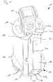
- a soil cultivation device 10 which is designed as a drilling bucket, is used in connection with the Figures 1 and 2 explained.
- a tubular housing which surrounds a base body 12 has been omitted for the sake of clarity.
- a floor 14 is arranged on the underside of the base body 12 and has a soil removal device 30 on its underside. Removed soil material can be received in an inner receiving space on the base body 12 via an opening (not shown) in the base.
- the bottom 14 is mounted pivotably about a horizontally directed pivot axis 15. So the bottom 14 can be swung open to empty the drilling bucket.
- the housing around the base body 12 is closed at the top by a cover plate 18 on which a connecting device 20 for connecting to a drill rod is attached.
- the connecting device 20 is designed as a so-called Kelly box, which can accommodate a square-shaped end of a drill rod.
- a drill rod can thus be received and fastened in the sleeve-shaped connecting device 20 in a rotationally fixed manner.
- the soil cultivation device 10 is provided with a pressure measuring arrangement 40, which has a first pressure measuring device 41 on a lower region of the base body 12 and a second pressure measuring device 42 has an upper region of the base body 12.
- the lower, first pressure measuring device 41 has a first hollow measuring body 45a, which is constructed in the shape of a ring from three tubular elements.
- the outwardly pointing outer measuring element is designed in an arc shape corresponding to an outer circumferential radius of the base body 12.
- a flexible measuring surface 48 can be arranged, which is deformed according to an external pressure from supporting liquid, possibly with removed soil material, and thus transfers an external pressure to an internal measuring fluid.
- the first hollow measuring body 45a is formed parallel to the horizontal base 14 and can be in contact with an outside or an outside environment via a recess in the base 14.
- a corresponding recess is also formed in the cover plate 18, with an inner wall 16 along the base body 12 forming a channel 17 through which support suspension can flow along the base body 12.
- the upper second pressure measuring device 42 has a second annular hollow measuring body 45b which is formed from four tubular elements.
- the second hollow measuring body 45b extends ring-like around the connecting device 20 on the top of the cover plate 18.
- the second hollow measuring body 45b is also designed with a flexible measuring surface for detecting an external ambient pressure, wherein the ambient pressure can be transferred to an internal measuring fluid.
- the first pressure measuring device 41 and the second pressure measuring device 42 are fluidically connected via a connecting line 44 which extends axially along the base body 12.
- a connecting line 44 which extends axially along the base body 12.
- the inner wall 16 is provided, which largely delimits and protects the connecting line 44 and also the first pressure measuring device 41 on the floor 14 from removed soil material in the interior of the base body 12.
- a sensor device 50 is connected to the connecting line 44 on the cover plate 18, with which a pressure difference between the first pressure measuring device 41 and the second pressure measuring device 42 can be determined.
- the sensor device 50 can have a conventional pressure sensor or also a flow meter which detects a movement of the measuring fluid in the pressure measuring arrangement 40 due to different pressures at the first pressure measuring device 41 and the second pressure measuring device 42.
- pressure sensors can also be arranged on the two pressure measuring devices 41, 42, with each of which an absolute pressure can be determined.
- the sensor device 50 and the further sensors are connected to a control unit of a soil cultivation device (not shown), the control unit controlling a vertical movement of the soil cultivation device 10 and / or a rotary drive for rotating the soil cultivation device 10 in accordance with the determined pressure values.
- the pressure measuring devices 41, 42 are arranged on an outside. If it is desired to detect the degree of filling, the first pressure measuring device 41 can be arranged in the inner receiving space of the base body 12.
Landscapes
- Engineering & Computer Science (AREA)
- Life Sciences & Earth Sciences (AREA)
- Mining & Mineral Resources (AREA)
- Geology (AREA)
- Physics & Mathematics (AREA)
- General Life Sciences & Earth Sciences (AREA)
- Environmental & Geological Engineering (AREA)
- Fluid Mechanics (AREA)
- Geochemistry & Mineralogy (AREA)
- Mechanical Engineering (AREA)
- Structural Engineering (AREA)
- Geophysics (AREA)
- Paleontology (AREA)
- General Engineering & Computer Science (AREA)
- Civil Engineering (AREA)
- Investigation Of Foundation Soil And Reinforcement Of Foundation Soil By Compacting Or Drainage (AREA)
- Earth Drilling (AREA)
- Measuring Fluid Pressure (AREA)
- Force Measurement Appropriate To Specific Purposes (AREA)
- Pit Excavations, Shoring, Fill Or Stabilisation Of Slopes (AREA)
- Production Of Multi-Layered Print Wiring Board (AREA)
Abstract
Description
- Die Erfindung betrifft eine Bodenbearbeitungsvorrichtung zum Erstellen eines im Wesentlichen vertikal verlaufenden Lochs im Boden, welches mit einer Stützflüssigkeit versehen ist, mit einem Grundkörper, einer Verbindungseinrichtung, welche an einem oberen Endbereich des Grundkörpers angeordnet ist, und einer Bodenabtragseinrichtung und/oder einer Bodenverdrängungseinrichtung, welche an einem unteren Endbereich des Grundkörpers angeordnet ist, gemäß dem Oberbegriff des Anspruchs 1.
- Weiterhin betrifft die Erfindung ein Verfahren zum Erstellen eines im Wesentlichen vertikalen Lochs im Boden mit einer solchen Bodenbearbeitungsvorrichtung gemäß dem Anspruch 13.
- Beispielsweise zur Erstellung von Gründungspfählen im Boden ist es bekannt, mit einem Bodenbearbeitungswerkzeug, etwa einem Bohreimer, ein Loch im Boden zu erstellen. Abhängig von der Art des umgebenden Bodens kann die Bohrung als eine verrohrte oder unverrohrte Bohrung hergestellt werden. Insbesondere im Falle einer unverrohrten Bohrung ist eine Stützflüssigkeit vorzusehen, welche das Bohrloch gegen ein Kollabieren abstützt.
- Beim Einsatz eines Bohreimers ist ein diskontinuierliches Bohren durchzuführen. Beim Abbohren füllt sich der Bohreimer mit abgetragenem Bodenmaterial, bis er vollständig oder zumindest weitgehend gefüllt ist. Sodann ist der Bohreimer aus dem mit Flüssigkeit gefüllten Loch herauszuziehen, wobei über der Oberfläche ein Bohrgerät zu einer Entleerposition schwenkt, an welcher der Bohreimer entleert werden kann. Anschließend wird der Bohreimer zurückgeschwenkt und wieder in das Bohrloch eingefahren, um einen weiteren Bohrschritt durchzuführen.
- Bei der Erstellung eines Lochs im Boden, welches mit einer Stützflüssigkeit befüllt ist, besteht das Problem, dass beim Rückziehen der Bodenbearbeitungsvorrichtung unterhalb der Bodenbearbeitungsvorrichtung im Loch ein Unterdruck entstehen kann. Wird dieser Unterdruck zu groß, kann Bodenmaterial von den Seitenwänden in das Loch stürzen. Dieses eingestürzte Bodenmaterial bedeutet nicht allein eine zusätzliche Arbeit, um dieses aus dem Loch zurückzuholen. Vielmehr besteht bei einem derartigen Einstürzen die Gefahr eines sogenannten Grundbruches, wobei durch das in das Loch eingestürzte Material der umgebende Boden derart geschwächt und destabilisiert wird, dass es zu größeren Setzungsbewegungen im Umgebungsbereich des Lochs kommt. Hierdurch können bestehende Baukörper beschädigt oder auch Baumaschinen zum Umsturz gebracht werden. Ein Grundbruch stellt eine erhebliche Gefahr für Menschen und Gegenstände dar, so dass umfassende Vorkehrungen gegen einen solchen Grundbruch zu treffen sind.
- Zur Vermeidung einer solchen Gefahr durch Entstehung eines Unterdrucks unter eine Bodenbearbeitungsvorrichtung bei einem Ziehen nach oben ist es bekannt, die Rückzugsgeschwindigkeit des Bodenbearbeitungswerkzeuges gering zu halten, so dass ein ausreichender Druckausgleich zwischen der Oberseite und der Unterseite der Bodenbearbeitungsvorrichtung im Loch erfolgen kann.
- Darüber hinaus besteht bei einem diskontinuierlichen Verfahren zur Erstellung eines Lochs etwa mit einem Bohreimer das Problem, dass eine korrekte Füllung des Bohreimers nur schwer zu kontrollieren ist. Denn beim Abbohren in den Boden weist das abgetragene Bodenmaterial häufig ein anderes Volumen auf, als der anstehende feste Boden.
- Wird ein Bohreimer bei einem Bohrschritt nicht hinreichend befüllt, sind zusätzliche Bohrschritte notwendig. Dies bedeutet einen zusätzlichen Zeit- und Kostenaufwand. Wird hingegen der Bohreimer überfüllt, kann das Bodenmaterial im Bohreimer so stark verdichtet werden, dass es beim Entleeren durch Aufklappen des Bodens nicht selbständig aus dem Bohreimer fällt. Es sind dann zusätzliche manuelle Vorgänge zum Entleeren und Reinigen des Bohreimers notwendig. Auch dies bedeutet einen zusätzlichen Zeit- und Kostenaufwand.
- Der Erfindung liegt die Aufgabe zugrunde, eine Bodenbearbeitungsvorrichtung und ein Verfahren anzugeben, mit welchen in besonders effizienter Weise ein Loch im Boden erstellt werden kann.
- Die Aufgabe wird zum einen durch eine Bodenbearbeitungsvorrichtung mit den Merkmalen des Anspruchs 1 und zum anderen durch ein Verfahren mit den Merkmalen des Anspruchs 13 gelöst. Bevorzugte Ausführungsformen der Erfindung sind in den abhängigen Ansprüchen angegeben.
- Die erfindungsgemäße Bodenbearbeitungsvorrichtung ist dadurch gekennzeichnet, dass an einem unteren Bereich des Grundkörpers eine erste Druckmesseinrichtung zum Messen eines ersten Umgebungsdrucks angeordnet ist und dass an einem oberen Bereich des Grundkörpers, welcher von dem unteren Bereich vertikal beabstandet ist, eine zweite Druckmesseinrichtung zum Messen eines zweiten Umgebungsdrucks angeordnet ist.
- Eine Grundidee der Erfindung kann darin gesehen werden, an einem Grundkörper einer Bodenbearbeitungsvorrichtung mindestens zwei Druckmesseinrichtungen vorzusehen. Die Druckmesseinrichtungen sind dabei so angeordnet, dass sich diese im Bohrloch an einem unteren Bereich des Grundkörpers sowie an einem oberen Bereich des Grundkörpers befinden. Auf diese Weise kann ein erster Umgebungsdruck in einem unteren Bereich des Grundkörpers und beabstandet dazu ein zweiter Umgebungsdruck an einem oberen Bereich des Grundkörpers im Bohrloch gemessen werden. Aufgrund der festen Beabstandung der beiden Druckmesseinrichtungen muss sich bei einem Vergleich der beiden gemessenen Umgebungsdrücke eine im Wesentlichen konstante Druckdifferenz ergeben, welche von der Konsistenz der Stützflüssigkeit abhängt. Abweichungen zu dieser Druckdifferenz oder zwischen den Messungen der beiden Druckmesseinrichtungen ermöglichen Aussagen etwa darüber, dass sich ein Unterdruck unter der Bodenbearbeitungsvorrichtung ausbildet oder eine Befüllung des Grundkörpers zunimmt oder abnimmt. Die Werte oder Daten der Druckmesseinrichtungen können daher für einen sicheren und effizienten Betrieb der Bodenbearbeitungsvorrichtung eingesetzt werden.
- Grundsätzlich können die Druckmesseinrichtungen beliebig ausgebildet sein, etwa als elektronische Drucksensoren. Eine bevorzugte Ausführungsform der Erfindung besteht darin, dass die erste Druckmesseinrichtung und/oder die zweite Druckmesseinrichtung mindestens einen hohlen Messkörper aufweisen, welcher mit einem Messfluid befüllt ist. Der Messkörper kann dabei ein Rohrköper oder ein aus Rohrkörpern zusammengesetzter Messkörper sein. Als Messfluid kann eine Flüssigkeit oder ein Gas vorgesehen sein. Bevorzugt wird Wasser oder ein Öl als Messfluid verwendet. Mit dem Messfluid können so eine oder mehrere Sensoreinrichtungen geschützt in Verbindung stehen.
- Eine besonders gute Druckmessung kann nach einer Weiterentwicklung der Erfindung dadurch erzielt werden, dass der Messkörper mindestens eine flexibel Messfläche aufweist, welche mit der Umgebung in Kontakt steht. Die Messfläche kann eine Folie, eine Membran oder ein fluiddichtes Gewebe sein, durch welches ein äußerer Umgebungsdruck durch die Stützflüssigkeit oder das Bodenmaterial auf das Messfluid übertragen werden kann. Die Messfläche kann gegebenenfalls durch eine Schutzeinrichtung, gegebenenfalls eine Schutzhülle mit einer Perforation, etwa durch ein Gitter, geschützt sein.
- Grundsätzlich kann der Messkörper als ein beliebiger hohler Körper gestaltet sein. Besonders effizient ist es, dass der Messkörper röhrenförmig ausgebildet ist. Der Messkörper kann dabei aus röhrenförmigen Standardmaterialien hergestellt werden. Der röhrenförmige Messkörper kann einen kreisringförmigen Querschnitt oder einen Vierkant- oder sonstigen polygonalen Querschnitt aufweisen.
- Für eine besonders aussagekräftige Druckmessung an einem Höhenbereich des Bodenbearbeitungswerkzeuges ist es nach einer Weiterbildung der Erfindung vorteilhaft, dass der Messkörper im Wesentlichen horizontal angeordnet ist. Vorzugsweise kann sich der Messkörper horizontal teilweise oder insgesamt um den Umfang der Bodenbearbeitungsvorrichtung strecken, so dass eine zuverlässige Druckmessung erfolgen kann. Horizontal im Sinne der Erfindung bedeutet eine Ausrichtung etwa senkrecht zur Längsachse des Bodenbearbeitungswerkzeuges und zur Bohrrichtung.
- Grundsätzlich kann die Erfindung durch zwei oder mehr separate Druckmesseinrichtngen verwirklicht werden, welche auch elektronische Sensoren aufweisen können. Eine besonders effiziente Messanordnung besteht nach einer Ausführungsvariante der Erfindung darin, dass die erste Druckmesseinrichtung und die zweite Druckmesseinrichtung über eine Verbindungsleitung in fluidischer Verbindung stehen und dass an der Verbindungsleitung eine Sensoreinrichtung angeordnet ist, mit welcher ein Druckunterschied zwischen einem ersten Druck an der ersten Druckmesseinrichtung und einem zweiten Druck an der zweiten Druckmesseinrichtung erfassbar ist. Der Druckunterschied kann dabei alternativ oder vorzugsweise ergänzend zu den zwei Einzeldruckmessungen erfasst werden. Ein unmittelbares Messen eines Druckunterschiedes lässt eine besonders zuverlässige Aussage darüber zu, ob sich beispielsweise ein Unterdruck am unteren Ende der Bodenbearbeitungsvorrichtung aufbaut, wie er beispielsweise bei einem zu schnellen Ziehen der Bodenbearbeitungsvorrichtung aus dem Loch entstehen kann.
- Grundsätzlich kann die Bodenbearbeitungsvorrichtung in einer beliebigen Weise ausgebildet sein. Bevorzugt ist es nach einer Weiterbildung der Erfindung, dass die Bodenbearbeitungsvorrichtung als ein Abtragsbohrwerkzeug, ein Verdrängerbohrwerkzeug oder eine Schlitzwandfräse ausgebildet ist. Ein Abtragsbohrwerkzeug weist an seiner Unterseite materialabtragende Abtragselemente auf, etwa Schneidzähne, Meißel oder Rollenmeißel. Das Bohrwerkzeug kann ein Bohreimer, eine Bohrschnecke oder insbesondere ein anderes diskontinuierlich arbeitendes Bohrwerkzeug sein. Weiter kann die Bodenbearbeitungsvorrichtung als ein Verdrängerbohrwerkzeug ausgebildet sein. Ein Verdrängerbohrwerkzeug weist dabei mindestens eine Verdrängerfläche auf, welche bei einem drehenden Antrieb anstehendes oder abgetragenes Bodenmaterial im Wesentlichen radial in die Bohrlochwandung verdrängt. Es kann auch eine Kombination zwischen Abtragsbohrwerkzeug und Verdrängerbohrwerkzeug vorgesehen sein. Darüber hinaus kann die Bodenbearbeitungsvorrichtung auch eine Schlitzwandfräse sein, die mindestens ein oder vorzugsweise mehrere Fräsräder am unteren Ende aufweist, welche drehend um quer zur Vortriebsrichtung gerichtete Drehachsen angetrieben werden.
- Mittels einer Schlitzwandfräse kann ein Loch oder Frässchlitz auch mit einem eckigen Querschnitt erstellt werden. Beim Ziehen einer Schlitzwandfräse besteht grundsätzlich ebenfalls die Gefahr eines Grundbruchs bei einem zu schnellen Ziehen ohne ausreichenden Druckausgleich zwischen der Oberseite und der Unterseite der Schlitzwandfräse.
- Die Erfindung umfasst weiterhin ein Bodenbearbeitungsgerät, welches zum Erstellen eines Lochs im Boden mit der zuvor beschriebenen Bodenbearbeitungsvorrichtung versehen ist, welche vertikal verstellbar und antreibbar angeordnet ist.
- Vorzugsweise weist ein derartiges Bodenbearbeitungsgerät eine Trägereinheit mit einem Oberwagen auf, welcher auf einem verfahrbaren Unterwagen drehbar gelagert ist. Der Unterwagen kann insbesondere ein Raupenfahrwerk aufweisen. Das Bodenbearbeitungsgerät kann insbesondere ein Bohrgerät oder eine Schlitzwandfräsvorrichtung mit Trägereinheit sein. An dem Oberwagen ist vorzugsweise ein im Wesentlichen vertikal gerichteter Mast angeordnet, entlang welchem die Bodenbearbeitungsvorrichtung vertikal verstellbar gelagert ist.
- Nach einer Weiterbildung der Erfindung ist es bevorzugt, dass eine Steuereinheit vorgesehen ist, welche mit der ersten Druckmesseinrichtung, der zweiten Druckmesseinrichtung und/oder der Sensoreinrichtung in Datenverbindung steht. Die Steuereinheit kann dabei Druckverläufe dokumentieren und/oder abhängig von den ermittelten Werten und Daten eine Steuerung des Bearbeitungsgerätes vornehmen.
- Besonders bevorzugt ist es dabei, dass die Steuereinheit ausgebildet ist, eine Vertikalbewegung und/oder einen Drehantrieb der Bodenbearbeitungsvorrichtung abhängig von Daten zu steuern, welche von der ersten Druckmesseinrichtung, der zweiten Druckmesseinrichtung und/oder der Sensoreinrichtung übertragen werden. Wird beispielsweise ein Anstieg der Druckdifferenz zwischen den zwei Druckmesseinrichtungen festgestellt, kann dies ein Hinweis auf den Aufbau eines Unterdrucks an der Bodenbearbeitungsvorrichtung sein. In diesem Fall kann eine Vertikalbewegung, etwa beim Ziehen der Vorrichtung aus dem Loch gestoppt oder soweit reduziert werden, bis sich wieder eine Druckdifferenz unter einem vorgegebenen Grenzwert einstellt. In gleicher Weise kann ein Drehantrieb etwa bei einem Bohrgerät oder ein Drehantrieb an Fräsrädern abhängig von den Druckwerten verändert werden, wobei beispielsweise Druckwerte ein Maß dafür sein können, wie viel und insbesondere ob zu viel oder zu wenig Bodenmaterial abgetragen wird.
- Eine weitere bevorzugte Ausführungsvariante des erfindungsgemäßen Bodenbearbeitungsgerätes kann darin bestehen, dass die Steuereinheit ausgebildet ist, basierend auf den Daten zum Druck an der Bodenbearbeitungsvorrichtung einen Füllgrad zu bestimmen. Steigt beispielsweise bei einem Bohreimer die Befüllung des Bohreimers mit Füllmaterial, kann dies an den ermittelten Druckwerten, insbesondere an der unteren ersten Druckmesseinrichtung, festgestellt werden. Grundsätzlich steigt der Druck an der unteren Druckmesseinrichtung mit zunehmendem Füllgrad und damit mit einer zunehmenden Auflast an abgetragenem Bodenmaterial.
- Wird dabei ein bestimmter Grenzwert erreicht, kann dies als ein Anzeichen dafür angesehen werden, dass ein ausreichender Füllgrad für einen Bohreimer erreicht ist. Alternativ oder ergänzend kann bei einer vollständigen Füllung eines Bohreimers bei einem weiterlaufenden Bohrantrieb festgestellt werden, dass sich keine oder eine andere Veränderung des Druckunterschiedes zwischen den beiden Druckmesseinrichtungen ergibt. Dies kann als ein Anzeichen dafür gesehen werden, dass ein bestimmter vollständiger Füllgrad bei einer Bodenbearbeitungsvorrichtung mit einem Aufnahmeraum gegeben ist.
- Bei dem erfindungsgemäßen Verfahren ist vorgesehen, dass das Loch beim Erstellen mit einer Stützflüssigkeit befüllt wird und mittels der ersten Druckmesseinrichtung ein erster Umgebungsdruck in einem unteren Bereich der Bodenbearbeitungsvorrichtung und mittels der zweiten Druckmesseinrichtung ein zweiter Umgebungsdruck in einem oberen Bereich der Bodenbearbeitungsvorrichtung gemessen werden. Das erfindungsgemäße Verfahren kann insbesondere mit der zuvor beschriebenen Bodenbearbeitungsvorrichtung beziehungsweise mit dem zuvor beschriebenen Bodenbearbeitungsgerät ausgeführt werden. Es können dabei die zuvor beschriebenen Vorteile erzielt werden.
- Eine vorteilhafte Verfahrensvariante besteht darin, dass die erste Druckmesseinrichtung mit der zweiten Druckmesseinrichtung über eine Verbindungsleitung fluidisch verbunden wird und dass an der Verbindungsleitung eine Sensoreinrichtung angeordnet ist, mit welcher ein Druckunterschied zwischen einem ersten Druck an der ersten Druckmesseinrichtung und ein zweiter Druck an der zweiten Druckmesseinrichtung erfasst wird. Mit der Sensoreinrichtung kann dabei in effizienter Weise unmittelbar ein Druckunterschied zwischen den beiden Druckmesseinrichtungen erfasst werden.
- Die Erfindung wird nachfolgend anhand eines bevorzugten Ausführungsbeispiels weiter beschrieben, welches schematisch in den beigefügten Zeichnungen dargestellt ist. In den Zeichnungen zeigen:
- Fig. 1
- eine perspektivische Ansicht eines Teils einer erfindungsgemäßen Bodenbearbeitungsvorrichtung; und
- Fig. 2
- ein Detail der Bodenbearbeitungsvorrichtung von
Fig. 1 betreffend eine Druckmessanordnung. - Eine erfindungsgemäße Bodenbearbeitungsvorrichtung 10, welche als ein Bohreimer ausgebildet ist, wird im Zusammenhang mit den
Figuren 1 und2 erläutert. Bei der Bodenbearbeitungsvorrichtung 10 ist aus Gründen der Übersichtlichkeit ein rohrförmiges Gehäuse weggelassen, welches einen Grundkörper 12 umgibt. An der Unterseite des Grundkörpers 12 ist ein Boden 14 angeordnet, welcher an seiner Unterseite eine Bodenabtragseinrichtung 30 aufweist. Über eine nicht dargestellte Öffnung im Boden kann abgetragenes Bodenmaterial in einen inneren Aufnahmeraum am Grundkörper 12 aufgenommen werden. Der Boden 14 ist um eine horizontal gerichtete Schwenkachse 15 schwenkbar gelagert. So kann der Boden 14 zum Entleeren des Bohreimers nach unten aufgeschwenkt werden. - Das Gehäuse um den Grundkörper 12 wird nach oben durch eine Deckplatte 18 abgeschlossen, auf welcher eine Verbindungseinrichtung 20 zum Verbinden mit einem Bohrgestänge angebracht ist. Die Verbindungseinrichtung 20 ist im dargestellten Ausführungsbeispiel als eine sogenannte Kellybox ausgebildet, welche ein vierkantförmiges Ende eines Bohrgestänges aufnehmen kann. Durch quer gerichtete Riegelbolzen kann so ein Bohrgestänge drehfest in der hülsenförmigen Verbindungseinrichtung 20 aufgenommen und befestigt werden.
- Gemäß der Erfindung ist die Bodenbearbeitungsvorrichtung 10 mit einer Druckmessanordnung 40 versehen, welche eine erste Druckmesseinrichtung 41 an einem unteren Bereich des Grundkörpers 12 und eine zweite Druckmesseinrichtung 42 an einem oberen Bereich des Grundkörpers 12 aufweist. Die untere erste Druckmesseinrichtung 41 weist einen ersten hohlen Messkörper 45a auf, welcher ringförmig aus drei röhrenförmigen Elementen aufgebaut ist. Das nach außen weisende äußere Messelement ist bogenförmig entsprechend einem Außenumfangsradius des Grundkörpers 12 ausgebildet. Insbesondere an einer Innenseite des ersten hohlen Messkörpers 45a kann eine flexible Messfläche 48 angeordnet sein, welche sich entsprechend einem Außendruck durch anstehende Stützflüssigkeit eventuell mit abgetragenem Bodenmaterial verformt und so einen Außendruck auf ein inneres Messfluid überträgt.
- Der erste hohle Messkörper 45a ist dabei parallel zum horizontalen Boden 14 ausgebildet und kann über eine Aussparung im Boden 14 mit einer Außenseite oder einer Außenumgebung in Kontakt stehen. Eine entsprechende Aussparung ist auch in der Deckplatte 18 ausgebildet, wobei durch eine Innenwand 16 entlang des Grundkörpers 12 ein Kanal 17 gebildet ist, durch welchen Stützsuspension entlang des Grundkörpers 12 strömen kann.
- Die obere zweite Druckmesseinrichtung 42 weist einen zweiten ringförmigen hohlen Messkörper 45b auf, welcher aus vier röhrenförmigen Elementen gebildet ist. Dabei erstreckt sich der zweite hohle Messkörper 45b ringartig um die Verbindungseinrichtung 20 an der Oberseite der Deckplatte 18. Der zweite hohle Messkörper 45b ist ebenfalls mit einer flexiblen Messfläche zum Erfassen eines äußeren Umgebungsdrucks ausgebildet, wobei der Umgebungsdruck auf ein inneres Messfluid übertragen werden kann.
- Die erste Druckmesseinrichtung 41 und die zweite Druckmesseinrichtung 42 sind über eine Verbindungsleitung 44 fluidisch verbunden, welche sich axial entlang des Grundkörpers 12 erstreckt. Zum Schutz der Verbindungsleitung 44 ist die Innenwand 16 vorgesehen, welche die Verbindungsleitung 44 und auch die erste Druckmesseinrichtung 41 am Boden 14 von abgetragenem Bodenmaterial im Innenraum des Grundkörpers 12 weitgehend abgrenzt und schützt. An der Deckplatte 18 ist an der Verbindungsleitung 44 eine Sensoreinrichtung 50 angeschlossen, mit welcher ein Druckunterschied zwischen der ersten Druckmesseinrichtung 41 und der zweiten Druckmesseinrichtung 42 feststellbar ist.
- Die Sensoreinrichtung 50 kann einen herkömmlichen Drucksensor oder auch einen Strömungsmesser aufweisen, welcher eine Bewegung des Messfluides in der Druckmessanordnung 40 aufgrund unterschiedlicher Drücke an der ersten Druckmesseinrichtung 41 und der zweiten Druckmesseinrichtung 42 feststellt. Darüber hinaus können an den beiden Druckmesseinrichtungen 41, 42 auch jeweils Drucksensoren angeordnet sein, mit welchen jeweils ein Absolutdruck ermittelt werden kann. Die Sensoreinrichtung 50 und die weiteren Sensoren sind mit einer Steuereinheit eines nicht dargestellten Bodenbearbeitungsgerätes verbunden, wobei die Steuereinheit entsprechend den ermittelten Druckwerten eine Vertikalbewegung der Bodenbearbeitungsvorrichtung 10 und/oder einen Drehantrieb zum Drehen der Bodenbearbeitungsvorrichtung 10 steuert.
- Bei dem dargestellten Ausführungsbeispiel sind die Druckmesseinrichtungen 41, 42 an einer Außenseite angeordnet. Wenn eine Erfassung des Füllgrades gewünscht ist, kann die erste Druckmesseinrichtung 41 im inneren Aufnahmeraum des Grundkörpers 12 angeordnet sein.
Claims (14)
- Bodenbearbeitungsvorrichtung zum Erstellen eines im Wesentlichen vertikal verlaufenden Lochs im Boden, welches mit einer Stützflüssigkeit versehen ist,
mit- einem Grundkörper (12),- einer Verbindungseinrichtung (20), welche an einem oberen Endbereich des Grundkörpers (12) angeordnet ist, und- einer Bodenabtragseinrichtung (30) und/oder einer Bodenverdrängungseinrichtung, welche an einem unteren Endbereich des Grundkörpers (12) angeordnet ist,dadurch gekennzeichnet,
dass an einem unteren Bereich des Grundkörpers (12) eine erste Druckmesseinrichtung (41) zum Messen eines ersten Umgebungsdrucks angeordnet ist und dass an einem oberen Bereich des Grundkörpers (12), welcher von dem unteren Bereich vertikal beabstandet ist, eine zweite Druckmesseinrichtung (42) zum Messen eines zweiten Umgebungsdrucks angeordnet ist. - Bodenbearbeitungsvorrichtung nach Anspruch 1,
dadurch gekennzeichnet,
dass die erste Druckmesseinrichtung (41) und/oder die zweite Druckmesseinrichtung (42) mindestens einen hohlen Messkörper (45a, 45b) aufweisen, welcher mit einem Messfluid befüllt ist. - Bodenbearbeitungsvorrichtung nach Anspruch 2,
dadurch gekennzeichnet,
dass der Messkörper (45a, 45b) mindestens eine flexible Messfläche (48) aufweist, welche mit der Umgebung in Kontakt steht. - Bodenbearbeitungsvorrichtung nach Anspruch 2 oder 3,
dadurch gekennzeichnet,
dass der Messkörper (45a, 45b) röhrenförmig ausgebildet ist. - Bodenbearbeitungsvorrichtung nach einem der Ansprüche 2 bis 4,
dadurch gekennzeichnet,
dass der Messkörper (45a, 45b) im Wesentlichen horizontal angeordnet ist. - Bodenbearbeitungsvorrichtung nach einem der Ansprüche 1 bis 5,
dadurch gekennzeichnet,
dass die erste Druckmesseinrichtung (41) und die zweite Druckmesseinrichtung (42) über eine Verbindungsleitung (44) in fluidischer Verbindung stehen und dass an der Verbindungsleitung (44) eine Sensoreinrichtung (50) angeordnet ist, mit welcher ein Druckunterschied zwischen einem ersten Druck an der ersten Druckmesseinrichtung (41) und einem zweiten Druck an der zweiten Druckmesseinrichtung (42) erfassbar ist. - Bodenbearbeitungsvorrichtung nach einem der Ansprüche 1 bis 6,
dadurch gekennzeichnet,
dass diese als ein Abtragsbohrwerkzeug, ein Verdrängerbohrwerkzeug oder eine Schlitzwandfräse ausgebildet ist. - Bodenbearbeitungsgerät,
dadurch gekennzeichnet,
dass zum Erstellen eines Loches im Boden eine Bodenbearbeitungsvorrichtung (10) nach einem der Ansprüche 1 bis 7 vertikal verstellbar und antreibbar angeordnet ist. - Bodenbearbeitungsgerät nach Anspruch 8,
dadurch gekennzeichnet,
dass eine Trägereinheit mit einem Oberwagen vorgesehen ist, welcher auf einem verfahrbaren Unterwagen drehbar gelagert ist. - Bodenbearbeitungsgerät nach Anspruch 8 oder 9,
dadurch gekennzeichnet,
dass eine Steuereinheit vorgesehen ist, welche mit der ersten Druckmesseinrichtung (41), der zweiten Druckmesseinrichtung (42) und/oder der Sensoreinrichtung (50) in Datenverbindung steht. - Bodenbearbeitungsgerät nach Anspruch 10,
dadurch gekennzeichnet,
dass die Steuereinheit ausgebildet ist, eine Vertikalbewegung und/oder einen Drehantrieb der Bodenbearbeitungsvorrichtung (10) abhängig von Daten zu steuern, welche von der ersten Druckmesseinrichtung (41), der zweiten Druckmesseinrichtung (42) und/oder der Sensoreinrichtung übertragen werden. - Bodenbearbeitungsgerät nach Anspruch 10 oder 11,
dadurch gekennzeichnet,
dass die Steuereinheit ausgebildet ist, basierend auf den Daten zum Druck an der Bodenbearbeitungsvorrichtung (10) einen Füllgrad zu bestimmen. - Verfahren zum Erstellen eines im Wesentlichen vertikalen Loches im Boden mit einer Bodenbearbeitungsvorrichtung (10) nach einem der Ansprüche 1 bis 7 oder einem Bodenbearbeitungsgerät nach einem der Ansprüche 8 bis 12,
wobei das Loch beim Erstellen mit einer Stützflüssigkeit befüllt wird und mittels der ersten Druckmesseinrichtung (41) ein erster Umgebungsdruck in einem unteren Bereich der Bodenbearbeitungsvorrichtung und mittels der zweiten Druckmesseinrichtung (42) ein zweiter Umgebungsdruck in einem oberen Bereich der Bodenbearbeitungsvorrichtung (10) gemessen werden. - Verfahren nach Anspruch 13,
dadurch gekennzeichnet,
dass die erste Druckmesseinrichtung (41) mit der zweiten Druckmesseinrichtung (42) über eine Verbindungsleitung (44) fluidisch verbunden wird und
dass an der Verbindungsleitung (44) eine Sensoreinrichtung (50) angeordnet ist, mit welcher ein Druckunterschied zwischen einem ersten Druck an der ersten Druckmesseinrichtung (41) und einem zweiten Druck an der zweiten Druckmesseinrichtung (42) erfasst wird.
Priority Applications (7)
| Application Number | Priority Date | Filing Date | Title |
|---|---|---|---|
| ES20162420T ES2965334T3 (es) | 2020-03-11 | 2020-03-11 | Dispositivo de trabajo del suelo y procedimiento para realizar un agujero sustancialmente vertical en el suelo |
| EP20162420.2A EP3879064B1 (de) | 2020-03-11 | 2020-03-11 | Bodenbearbeitungsvorrichtung und verfahren zum erstellen eines im wesentlichen vertikalen lochs im boden |
| CA3170952A CA3170952C (en) | 2020-03-11 | 2021-01-27 | Soil working device and method for creating a substantially vertical h ole in the ground |
| CN202180019840.0A CN115176065B (zh) | 2020-03-11 | 2021-01-27 | 用于在土壤中生成基本上竖直的孔的土壤加工装置和方法 |
| US17/905,807 US12110784B2 (en) | 2020-03-11 | 2021-01-27 | Soil working device and method for creating a substantially vertical hole in the ground |
| AU2021234003A AU2021234003B2 (en) | 2020-03-11 | 2021-01-27 | Soil working device and method for creating a substantially vertical hole in the ground |
| PCT/EP2021/051789 WO2021180392A1 (de) | 2020-03-11 | 2021-01-27 | Bodenbearbeitungsvorrichtung und verfahren zum erstellen eines im wesentlichen vertikalen lochs im boden |
Applications Claiming Priority (1)
| Application Number | Priority Date | Filing Date | Title |
|---|---|---|---|
| EP20162420.2A EP3879064B1 (de) | 2020-03-11 | 2020-03-11 | Bodenbearbeitungsvorrichtung und verfahren zum erstellen eines im wesentlichen vertikalen lochs im boden |
Publications (3)
| Publication Number | Publication Date |
|---|---|
| EP3879064A1 true EP3879064A1 (de) | 2021-09-15 |
| EP3879064B1 EP3879064B1 (de) | 2023-08-09 |
| EP3879064C0 EP3879064C0 (de) | 2023-08-09 |
Family
ID=69804668
Family Applications (1)
| Application Number | Title | Priority Date | Filing Date |
|---|---|---|---|
| EP20162420.2A Active EP3879064B1 (de) | 2020-03-11 | 2020-03-11 | Bodenbearbeitungsvorrichtung und verfahren zum erstellen eines im wesentlichen vertikalen lochs im boden |
Country Status (6)
| Country | Link |
|---|---|
| US (1) | US12110784B2 (de) |
| EP (1) | EP3879064B1 (de) |
| CN (1) | CN115176065B (de) |
| AU (1) | AU2021234003B2 (de) |
| ES (1) | ES2965334T3 (de) |
| WO (1) | WO2021180392A1 (de) |
Cited By (2)
| Publication number | Priority date | Publication date | Assignee | Title |
|---|---|---|---|---|
| EP4455445A1 (de) | 2023-04-25 | 2024-10-30 | BAUER Maschinen GmbH | Bohrwerkzeug und verfahren zum erstellen einer bohrung im boden |
| EP4491843A1 (de) | 2023-07-13 | 2025-01-15 | BAUER Maschinen GmbH | Kastenbohrer und verfahren zum erstellen einer bohrung im boden |
Citations (5)
| Publication number | Priority date | Publication date | Assignee | Title |
|---|---|---|---|---|
| DE3440727A1 (de) * | 1984-11-07 | 1986-05-07 | E + M Bohr GmbH, 8670 Hof | Bohrwerkzeug |
| WO1999000575A2 (en) * | 1997-06-27 | 1999-01-07 | Baker Hughes Incorporated | Drilling system with sensors for determining properties of drilling fluid downhole |
| CN2791234Y (zh) * | 2004-11-11 | 2006-06-28 | 鞠浩文 | 电动钻井机 |
| CN201943581U (zh) * | 2010-12-24 | 2011-08-24 | 北京市三一重机有限公司 | 内螺旋筒式钻具 |
| US20130269220A1 (en) * | 2012-04-16 | 2013-10-17 | Pengo Corporation | Drilling Bucket |
Family Cites Families (21)
| Publication number | Priority date | Publication date | Assignee | Title |
|---|---|---|---|---|
| US5570975A (en) * | 1994-06-27 | 1996-11-05 | Reinert, Sr.; Gary L. | Metal foundation push-it and installation apparatus and method |
| US5542786A (en) * | 1995-03-27 | 1996-08-06 | Berkel & Company Contractors, Inc. | Apparatus for monitoring grout pressure during construction of auger pressure grouted piling |
| US6033152A (en) * | 1997-04-11 | 2000-03-07 | Berkel & Company Contractors, Inc. | Pile forming apparatus |
| US9169611B2 (en) * | 2000-06-15 | 2015-10-27 | Geopier Foundation Company, Inc. | Method and apparatus for building support piers from one or more successive lifts formed in a soil matrix |
| WO2003044283A1 (en) * | 2001-11-20 | 2003-05-30 | Gary Reinert | Segmented foundation installation apparatus and method of installation therefor |
| JP2004020531A (ja) * | 2002-06-20 | 2004-01-22 | Terumu:Kk | 土壌調査方法 |
| AT414258B (de) * | 2002-09-19 | 2006-10-15 | Sigma Consult Gmbh | Bohrkopf |
| US7404449B2 (en) * | 2003-05-12 | 2008-07-29 | Bermingham Construction Limited | Pile driving control apparatus and pile driving system |
| US20050100415A1 (en) * | 2003-11-06 | 2005-05-12 | Larovere Tom A. | Profiler for installation of foundation screw anchors |
| RU2252296C1 (ru) * | 2004-08-25 | 2005-05-20 | Каширский Владимир Иванович | Способ испытания грунтов винтовым штампом и устройство для его осуществления |
| US7380462B2 (en) * | 2005-03-25 | 2008-06-03 | G-Tech. Co., Ltd. | Apparatus and method for measuring supporting force of large diameter ferroconcrete piles |
| US7987904B1 (en) * | 2006-01-23 | 2011-08-02 | Rose James A | Sealed well cellar |
| US7775299B2 (en) * | 2007-04-26 | 2010-08-17 | Waqar Khan | Method and apparatus for programmable pressure drilling and programmable gradient drilling, and completion |
| EP2231935B1 (de) * | 2007-12-31 | 2019-09-04 | Soles Tech. Società Cooperativa | Verfahren zum anheben eines fundaments für ein gebäude |
| US8596922B2 (en) * | 2009-01-12 | 2013-12-03 | University Of Florida Research Foundation, Inc. | Systems and methods for inserting and securing foundation members using a combination of jets and fluidized concrete |
| US20120308308A1 (en) * | 2011-06-03 | 2012-12-06 | Stewart Thomas C | Foundation support installer |
| CN105840173B (zh) * | 2016-05-18 | 2023-09-08 | 中石化胜利石油工程有限公司培训中心 | 一种钻井修正器及方法 |
| EP3336301B1 (de) * | 2016-12-19 | 2023-09-13 | BAUER Maschinen GmbH | Drehbohrwerkzeug und verfahren zum erstellen einer bohrung |
| CN109440762B (zh) * | 2018-11-14 | 2020-10-16 | 浙江景昌建设有限公司 | 一种排水泵站用灌注桩的施工方法 |
| US10640945B1 (en) * | 2019-05-03 | 2020-05-05 | Bahman Niroumand | Systems and methods for making compacted aggregate piers in a soil matrix |
| EP4015766B1 (de) * | 2020-12-21 | 2023-07-12 | BAUER Spezialtiefbau GmbH | Tiefbauwerkzeug und tiefbauverfahren |
-
2020
- 2020-03-11 ES ES20162420T patent/ES2965334T3/es active Active
- 2020-03-11 EP EP20162420.2A patent/EP3879064B1/de active Active
-
2021
- 2021-01-27 AU AU2021234003A patent/AU2021234003B2/en active Active
- 2021-01-27 CN CN202180019840.0A patent/CN115176065B/zh active Active
- 2021-01-27 WO PCT/EP2021/051789 patent/WO2021180392A1/de not_active Ceased
- 2021-01-27 US US17/905,807 patent/US12110784B2/en active Active
Patent Citations (5)
| Publication number | Priority date | Publication date | Assignee | Title |
|---|---|---|---|---|
| DE3440727A1 (de) * | 1984-11-07 | 1986-05-07 | E + M Bohr GmbH, 8670 Hof | Bohrwerkzeug |
| WO1999000575A2 (en) * | 1997-06-27 | 1999-01-07 | Baker Hughes Incorporated | Drilling system with sensors for determining properties of drilling fluid downhole |
| CN2791234Y (zh) * | 2004-11-11 | 2006-06-28 | 鞠浩文 | 电动钻井机 |
| CN201943581U (zh) * | 2010-12-24 | 2011-08-24 | 北京市三一重机有限公司 | 内螺旋筒式钻具 |
| US20130269220A1 (en) * | 2012-04-16 | 2013-10-17 | Pengo Corporation | Drilling Bucket |
Cited By (3)
| Publication number | Priority date | Publication date | Assignee | Title |
|---|---|---|---|---|
| EP4455445A1 (de) | 2023-04-25 | 2024-10-30 | BAUER Maschinen GmbH | Bohrwerkzeug und verfahren zum erstellen einer bohrung im boden |
| EP4491843A1 (de) | 2023-07-13 | 2025-01-15 | BAUER Maschinen GmbH | Kastenbohrer und verfahren zum erstellen einer bohrung im boden |
| WO2025012043A1 (de) | 2023-07-13 | 2025-01-16 | Bauer Maschinen Gmbh | Kastenbohrer und verfahren zum erstellen einer bohrung im boden |
Also Published As
| Publication number | Publication date |
|---|---|
| US12110784B2 (en) | 2024-10-08 |
| WO2021180392A1 (de) | 2021-09-16 |
| EP3879064B1 (de) | 2023-08-09 |
| CA3170952A1 (en) | 2021-09-16 |
| AU2021234003A1 (en) | 2022-09-29 |
| CN115176065A (zh) | 2022-10-11 |
| US20240209726A1 (en) | 2024-06-27 |
| AU2021234003B2 (en) | 2024-02-15 |
| CN115176065B (zh) | 2025-10-24 |
| EP3879064C0 (de) | 2023-08-09 |
| ES2965334T3 (es) | 2024-04-12 |
Similar Documents
| Publication | Publication Date | Title |
|---|---|---|
| DE69606647T3 (de) | Verfahren zum erzeugen eines pfahles durch schneckenbohren | |
| EP3081737B2 (de) | Bohrgerät zum erstellen einer verrohrten bohrung und verfahren zum betreiben eines bohrgerätes | |
| EP2543770B1 (de) | Vorrichtung und Verfahren zum Vermessen von Düsenstrahlsäulen im Untergrund | |
| EP2815033B1 (de) | Erdbohrgerät und verfahren zum erdbohren | |
| EP2770156B1 (de) | Bohrwerkzeug und Verfahren zum Erdbohren | |
| EP3124740B1 (de) | Bohrgerät und verfahren zum erstellen einer bohrung von einer schwimmenden plattform | |
| EP3879064B1 (de) | Bodenbearbeitungsvorrichtung und verfahren zum erstellen eines im wesentlichen vertikalen lochs im boden | |
| EP3287588B1 (de) | Arbeitsmaschine und verfahren zum bearbeiten eines bodens | |
| EP1849918B1 (de) | Bohrgerät und Verfahren zum Erstellen einer Bohrsäule im Boden | |
| EP1974122B1 (de) | Vorrichtung und verfahren zum herstellen von bodenkörpern im untergrund | |
| EP4015766B1 (de) | Tiefbauwerkzeug und tiefbauverfahren | |
| EP4455445B1 (de) | Bohrwerkzeug und verfahren zum erstellen einer bohrung im boden | |
| EP3819433B1 (de) | Bodenabtragsvorrichtung und verfahren zum erstellen eines loches im boden | |
| EP4063568B1 (de) | Messanordnung und abtragsvorrichtung mit einer messanordnung | |
| EP3299572B1 (de) | Verfahren und bohranordnung zum verrohrten bohren | |
| DE3826623C2 (de) | ||
| EP3907371B1 (de) | Arbeitsmaschine und verfahren zum bearbeiten eines bodens | |
| CH683861A5 (de) | Tunnelvortriebsmaschine. | |
| DE3823784C2 (de) | ||
| DE202018104624U1 (de) | Bohrgerät | |
| DE2428870A1 (de) | Verfahren und vorrichtung zur herstellung von sandpfaehlen | |
| EP4491843B1 (de) | Kastenbohrer und verfahren zum erstellen einer bohrung im boden | |
| DE3911624A1 (de) | Schlitzwandfraese | |
| EP2245232B1 (de) | Vorrichtung und verfahren zum einbringen von bohrungen ins erdreich, deren querschnitte sich teilweise überschneiden | |
| EP4689347A1 (de) | Überwachungsvorrichtung und verfahren zur überwachung einer möglichen über-/unterentnahme von boden während des bohrens einer bohrung im boden |
Legal Events
| Date | Code | Title | Description |
|---|---|---|---|
| PUAI | Public reference made under article 153(3) epc to a published international application that has entered the european phase |
Free format text: ORIGINAL CODE: 0009012 |
|
| STAA | Information on the status of an ep patent application or granted ep patent |
Free format text: STATUS: THE APPLICATION HAS BEEN PUBLISHED |
|
| AK | Designated contracting states |
Kind code of ref document: A1 Designated state(s): AL AT BE BG CH CY CZ DE DK EE ES FI FR GB GR HR HU IE IS IT LI LT LU LV MC MK MT NL NO PL PT RO RS SE SI SK SM TR |
|
| STAA | Information on the status of an ep patent application or granted ep patent |
Free format text: STATUS: REQUEST FOR EXAMINATION WAS MADE |
|
| 17P | Request for examination filed |
Effective date: 20210923 |
|
| RBV | Designated contracting states (corrected) |
Designated state(s): AL AT BE BG CH CY CZ DE DK EE ES FI FR GB GR HR HU IE IS IT LI LT LU LV MC MK MT NL NO PL PT RO RS SE SI SK SM TR |
|
| STAA | Information on the status of an ep patent application or granted ep patent |
Free format text: STATUS: EXAMINATION IS IN PROGRESS |
|
| 17Q | First examination report despatched |
Effective date: 20220302 |
|
| GRAP | Despatch of communication of intention to grant a patent |
Free format text: ORIGINAL CODE: EPIDOSNIGR1 |
|
| STAA | Information on the status of an ep patent application or granted ep patent |
Free format text: STATUS: GRANT OF PATENT IS INTENDED |
|
| GRAJ | Information related to disapproval of communication of intention to grant by the applicant or resumption of examination proceedings by the epo deleted |
Free format text: ORIGINAL CODE: EPIDOSDIGR1 |
|
| STAA | Information on the status of an ep patent application or granted ep patent |
Free format text: STATUS: EXAMINATION IS IN PROGRESS |
|
| GRAP | Despatch of communication of intention to grant a patent |
Free format text: ORIGINAL CODE: EPIDOSNIGR1 |
|
| STAA | Information on the status of an ep patent application or granted ep patent |
Free format text: STATUS: GRANT OF PATENT IS INTENDED |
|
| INTG | Intention to grant announced |
Effective date: 20230221 |
|
| INTC | Intention to grant announced (deleted) | ||
| INTG | Intention to grant announced |
Effective date: 20230320 |
|
| GRAS | Grant fee paid |
Free format text: ORIGINAL CODE: EPIDOSNIGR3 |
|
| GRAA | (expected) grant |
Free format text: ORIGINAL CODE: 0009210 |
|
| STAA | Information on the status of an ep patent application or granted ep patent |
Free format text: STATUS: THE PATENT HAS BEEN GRANTED |
|
| AK | Designated contracting states |
Kind code of ref document: B1 Designated state(s): AL AT BE BG CH CY CZ DE DK EE ES FI FR GB GR HR HU IE IS IT LI LT LU LV MC MK MT NL NO PL PT RO RS SE SI SK SM TR |
|
| REG | Reference to a national code |
Ref country code: GB Ref legal event code: FG4D Free format text: NOT ENGLISH |
|
| REG | Reference to a national code |
Ref country code: CH Ref legal event code: EP |
|
| REG | Reference to a national code |
Ref country code: IE Ref legal event code: FG4D Free format text: LANGUAGE OF EP DOCUMENT: GERMAN |
|
| REG | Reference to a national code |
Ref country code: DE Ref legal event code: R096 Ref document number: 502020004568 Country of ref document: DE |
|
| U01 | Request for unitary effect filed |
Effective date: 20230821 |
|
| U07 | Unitary effect registered |
Designated state(s): AT BE BG DE DK EE FI FR IT LT LU LV MT NL PT SE SI Effective date: 20230825 |
|
| PG25 | Lapsed in a contracting state [announced via postgrant information from national office to epo] |
Ref country code: GR Free format text: LAPSE BECAUSE OF FAILURE TO SUBMIT A TRANSLATION OF THE DESCRIPTION OR TO PAY THE FEE WITHIN THE PRESCRIBED TIME-LIMIT Effective date: 20231110 |
|
| PG25 | Lapsed in a contracting state [announced via postgrant information from national office to epo] |
Ref country code: IS Free format text: LAPSE BECAUSE OF FAILURE TO SUBMIT A TRANSLATION OF THE DESCRIPTION OR TO PAY THE FEE WITHIN THE PRESCRIBED TIME-LIMIT Effective date: 20231209 |
|
| PG25 | Lapsed in a contracting state [announced via postgrant information from national office to epo] |
Ref country code: RS Free format text: LAPSE BECAUSE OF FAILURE TO SUBMIT A TRANSLATION OF THE DESCRIPTION OR TO PAY THE FEE WITHIN THE PRESCRIBED TIME-LIMIT Effective date: 20230809 Ref country code: NO Free format text: LAPSE BECAUSE OF FAILURE TO SUBMIT A TRANSLATION OF THE DESCRIPTION OR TO PAY THE FEE WITHIN THE PRESCRIBED TIME-LIMIT Effective date: 20231109 Ref country code: IS Free format text: LAPSE BECAUSE OF FAILURE TO SUBMIT A TRANSLATION OF THE DESCRIPTION OR TO PAY THE FEE WITHIN THE PRESCRIBED TIME-LIMIT Effective date: 20231209 Ref country code: HR Free format text: LAPSE BECAUSE OF FAILURE TO SUBMIT A TRANSLATION OF THE DESCRIPTION OR TO PAY THE FEE WITHIN THE PRESCRIBED TIME-LIMIT Effective date: 20230809 Ref country code: GR Free format text: LAPSE BECAUSE OF FAILURE TO SUBMIT A TRANSLATION OF THE DESCRIPTION OR TO PAY THE FEE WITHIN THE PRESCRIBED TIME-LIMIT Effective date: 20231110 |
|
| PG25 | Lapsed in a contracting state [announced via postgrant information from national office to epo] |
Ref country code: PL Free format text: LAPSE BECAUSE OF FAILURE TO SUBMIT A TRANSLATION OF THE DESCRIPTION OR TO PAY THE FEE WITHIN THE PRESCRIBED TIME-LIMIT Effective date: 20230809 |
|
| REG | Reference to a national code |
Ref country code: ES Ref legal event code: FG2A Ref document number: 2965334 Country of ref document: ES Kind code of ref document: T3 Effective date: 20240412 |
|
| U20 | Renewal fee for the european patent with unitary effect paid |
Year of fee payment: 5 Effective date: 20240312 |
|
| PG25 | Lapsed in a contracting state [announced via postgrant information from national office to epo] |
Ref country code: SM Free format text: LAPSE BECAUSE OF FAILURE TO SUBMIT A TRANSLATION OF THE DESCRIPTION OR TO PAY THE FEE WITHIN THE PRESCRIBED TIME-LIMIT Effective date: 20230809 Ref country code: RO Free format text: LAPSE BECAUSE OF FAILURE TO SUBMIT A TRANSLATION OF THE DESCRIPTION OR TO PAY THE FEE WITHIN THE PRESCRIBED TIME-LIMIT Effective date: 20230809 Ref country code: CZ Free format text: LAPSE BECAUSE OF FAILURE TO SUBMIT A TRANSLATION OF THE DESCRIPTION OR TO PAY THE FEE WITHIN THE PRESCRIBED TIME-LIMIT Effective date: 20230809 Ref country code: SK Free format text: LAPSE BECAUSE OF FAILURE TO SUBMIT A TRANSLATION OF THE DESCRIPTION OR TO PAY THE FEE WITHIN THE PRESCRIBED TIME-LIMIT Effective date: 20230809 |
|
| REG | Reference to a national code |
Ref country code: DE Ref legal event code: R097 Ref document number: 502020004568 Country of ref document: DE |
|
| PLBE | No opposition filed within time limit |
Free format text: ORIGINAL CODE: 0009261 |
|
| STAA | Information on the status of an ep patent application or granted ep patent |
Free format text: STATUS: NO OPPOSITION FILED WITHIN TIME LIMIT |
|
| 26N | No opposition filed |
Effective date: 20240513 |
|
| REG | Reference to a national code |
Ref country code: CH Ref legal event code: PL |
|
| PG25 | Lapsed in a contracting state [announced via postgrant information from national office to epo] |
Ref country code: MC Free format text: LAPSE BECAUSE OF FAILURE TO SUBMIT A TRANSLATION OF THE DESCRIPTION OR TO PAY THE FEE WITHIN THE PRESCRIBED TIME-LIMIT Effective date: 20230809 |
|
| PG25 | Lapsed in a contracting state [announced via postgrant information from national office to epo] |
Ref country code: MC Free format text: LAPSE BECAUSE OF FAILURE TO SUBMIT A TRANSLATION OF THE DESCRIPTION OR TO PAY THE FEE WITHIN THE PRESCRIBED TIME-LIMIT Effective date: 20230809 |
|
| PG25 | Lapsed in a contracting state [announced via postgrant information from national office to epo] |
Ref country code: IE Free format text: LAPSE BECAUSE OF NON-PAYMENT OF DUE FEES Effective date: 20240311 |
|
| PG25 | Lapsed in a contracting state [announced via postgrant information from national office to epo] |
Ref country code: IE Free format text: LAPSE BECAUSE OF NON-PAYMENT OF DUE FEES Effective date: 20240311 Ref country code: CH Free format text: LAPSE BECAUSE OF NON-PAYMENT OF DUE FEES Effective date: 20240331 |
|
| PGFP | Annual fee paid to national office [announced via postgrant information from national office to epo] |
Ref country code: GB Payment date: 20250324 Year of fee payment: 6 |
|
| U20 | Renewal fee for the european patent with unitary effect paid |
Year of fee payment: 6 Effective date: 20250327 |
|
| PGFP | Annual fee paid to national office [announced via postgrant information from national office to epo] |
Ref country code: ES Payment date: 20250403 Year of fee payment: 6 |
|
| PG25 | Lapsed in a contracting state [announced via postgrant information from national office to epo] |
Ref country code: CY Free format text: LAPSE BECAUSE OF FAILURE TO SUBMIT A TRANSLATION OF THE DESCRIPTION OR TO PAY THE FEE WITHIN THE PRESCRIBED TIME-LIMIT; INVALID AB INITIO Effective date: 20200311 |
|
| PG25 | Lapsed in a contracting state [announced via postgrant information from national office to epo] |
Ref country code: HU Free format text: LAPSE BECAUSE OF FAILURE TO SUBMIT A TRANSLATION OF THE DESCRIPTION OR TO PAY THE FEE WITHIN THE PRESCRIBED TIME-LIMIT; INVALID AB INITIO Effective date: 20200311 |
|
| PG25 | Lapsed in a contracting state [announced via postgrant information from national office to epo] |
Ref country code: TR Free format text: LAPSE BECAUSE OF FAILURE TO SUBMIT A TRANSLATION OF THE DESCRIPTION OR TO PAY THE FEE WITHIN THE PRESCRIBED TIME-LIMIT Effective date: 20230809 |