EP3878766A1 - Container for spinal drainage kit - Google Patents
Container for spinal drainage kit Download PDFInfo
- Publication number
- EP3878766A1 EP3878766A1 EP19881246.3A EP19881246A EP3878766A1 EP 3878766 A1 EP3878766 A1 EP 3878766A1 EP 19881246 A EP19881246 A EP 19881246A EP 3878766 A1 EP3878766 A1 EP 3878766A1
- Authority
- EP
- European Patent Office
- Prior art keywords
- lid
- chamber
- drainage kit
- spinal
- container
- Prior art date
- Legal status (The legal status is an assumption and is not a legal conclusion. Google has not performed a legal analysis and makes no representation as to the accuracy of the status listed.)
- Granted
Links
Images





Classifications
-
- A—HUMAN NECESSITIES
- A61—MEDICAL OR VETERINARY SCIENCE; HYGIENE
- A61B—DIAGNOSIS; SURGERY; IDENTIFICATION
- A61B50/00—Containers, covers, furniture or holders specially adapted for surgical or diagnostic appliances or instruments, e.g. sterile covers
- A61B50/20—Holders specially adapted for surgical or diagnostic appliances or instruments
-
- A—HUMAN NECESSITIES
- A61—MEDICAL OR VETERINARY SCIENCE; HYGIENE
- A61M—DEVICES FOR INTRODUCING MEDIA INTO, OR ONTO, THE BODY; DEVICES FOR TRANSDUCING BODY MEDIA OR FOR TAKING MEDIA FROM THE BODY; DEVICES FOR PRODUCING OR ENDING SLEEP OR STUPOR
- A61M27/00—Drainage appliance for wounds or the like, i.e. wound drains, implanted drains
-
- A—HUMAN NECESSITIES
- A61—MEDICAL OR VETERINARY SCIENCE; HYGIENE
- A61B—DIAGNOSIS; SURGERY; IDENTIFICATION
- A61B50/00—Containers, covers, furniture or holders specially adapted for surgical or diagnostic appliances or instruments, e.g. sterile covers
- A61B50/30—Containers specially adapted for packaging, protecting, dispensing, collecting or disposing of surgical or diagnostic appliances or instruments
-
- A—HUMAN NECESSITIES
- A61—MEDICAL OR VETERINARY SCIENCE; HYGIENE
- A61M—DEVICES FOR INTRODUCING MEDIA INTO, OR ONTO, THE BODY; DEVICES FOR TRANSDUCING BODY MEDIA OR FOR TAKING MEDIA FROM THE BODY; DEVICES FOR PRODUCING OR ENDING SLEEP OR STUPOR
- A61M1/00—Suction or pumping devices for medical purposes; Devices for carrying-off, for treatment of, or for carrying-over, body-liquids; Drainage systems
- A61M1/84—Drainage tubes; Aspiration tips
-
- A—HUMAN NECESSITIES
- A61—MEDICAL OR VETERINARY SCIENCE; HYGIENE
- A61M—DEVICES FOR INTRODUCING MEDIA INTO, OR ONTO, THE BODY; DEVICES FOR TRANSDUCING BODY MEDIA OR FOR TAKING MEDIA FROM THE BODY; DEVICES FOR PRODUCING OR ENDING SLEEP OR STUPOR
- A61M25/00—Catheters; Hollow probes
- A61M25/002—Packages specially adapted therefor ; catheter kit packages
-
- B—PERFORMING OPERATIONS; TRANSPORTING
- B65—CONVEYING; PACKING; STORING; HANDLING THIN OR FILAMENTARY MATERIAL
- B65D—CONTAINERS FOR STORAGE OR TRANSPORT OF ARTICLES OR MATERIALS, e.g. BAGS, BARRELS, BOTTLES, BOXES, CANS, CARTONS, CRATES, DRUMS, JARS, TANKS, HOPPERS, FORWARDING CONTAINERS; ACCESSORIES, CLOSURES, OR FITTINGS THEREFOR; PACKAGING ELEMENTS; PACKAGES
- B65D1/00—Rigid or semi-rigid containers having bodies formed in one piece, e.g. by casting metallic material, by moulding plastics, by blowing vitreous material, by throwing ceramic material, by moulding pulped fibrous material or by deep-drawing operations performed on sheet material
- B65D1/22—Boxes or like containers with side walls of substantial depth for enclosing contents
- B65D1/26—Thin-walled containers, e.g. formed by deep-drawing operations
-
- B—PERFORMING OPERATIONS; TRANSPORTING
- B65—CONVEYING; PACKING; STORING; HANDLING THIN OR FILAMENTARY MATERIAL
- B65D—CONTAINERS FOR STORAGE OR TRANSPORT OF ARTICLES OR MATERIALS, e.g. BAGS, BARRELS, BOTTLES, BOXES, CANS, CARTONS, CRATES, DRUMS, JARS, TANKS, HOPPERS, FORWARDING CONTAINERS; ACCESSORIES, CLOSURES, OR FITTINGS THEREFOR; PACKAGING ELEMENTS; PACKAGES
- B65D75/00—Packages comprising articles or materials partially or wholly enclosed in strips, sheets, blanks, tubes or webs of flexible sheet material, e.g. in folded wrappers
- B65D75/28—Articles or materials wholly enclosed in composite wrappers, i.e. wrappers formed by associating or interconnecting two or more sheets or blanks
- B65D75/30—Articles or materials enclosed between two opposed sheets or blanks having their margins united, e.g. by pressure-sensitive adhesive, crimping, heat-sealing, or welding
- B65D75/32—Articles or materials enclosed between two opposed sheets or blanks having their margins united, e.g. by pressure-sensitive adhesive, crimping, heat-sealing, or welding one or both sheets or blanks being recessed to accommodate contents
-
- A—HUMAN NECESSITIES
- A61—MEDICAL OR VETERINARY SCIENCE; HYGIENE
- A61B—DIAGNOSIS; SURGERY; IDENTIFICATION
- A61B50/00—Containers, covers, furniture or holders specially adapted for surgical or diagnostic appliances or instruments, e.g. sterile covers
- A61B2050/005—Containers, covers, furniture or holders specially adapted for surgical or diagnostic appliances or instruments, e.g. sterile covers with a lid or cover
- A61B2050/0051—Containers, covers, furniture or holders specially adapted for surgical or diagnostic appliances or instruments, e.g. sterile covers with a lid or cover closable by rotation
- A61B2050/0056—Containers, covers, furniture or holders specially adapted for surgical or diagnostic appliances or instruments, e.g. sterile covers with a lid or cover closable by rotation about a lateral axis in the lid plane
-
- A—HUMAN NECESSITIES
- A61—MEDICAL OR VETERINARY SCIENCE; HYGIENE
- A61B—DIAGNOSIS; SURGERY; IDENTIFICATION
- A61B50/00—Containers, covers, furniture or holders specially adapted for surgical or diagnostic appliances or instruments, e.g. sterile covers
- A61B2050/005—Containers, covers, furniture or holders specially adapted for surgical or diagnostic appliances or instruments, e.g. sterile covers with a lid or cover
- A61B2050/0067—Types of closures or fasteners
- A61B2050/0082—Rib-and-groove connection
-
- A—HUMAN NECESSITIES
- A61—MEDICAL OR VETERINARY SCIENCE; HYGIENE
- A61M—DEVICES FOR INTRODUCING MEDIA INTO, OR ONTO, THE BODY; DEVICES FOR TRANSDUCING BODY MEDIA OR FOR TAKING MEDIA FROM THE BODY; DEVICES FOR PRODUCING OR ENDING SLEEP OR STUPOR
- A61M2202/00—Special media to be introduced, removed or treated
- A61M2202/10—Bone-marrow
-
- A—HUMAN NECESSITIES
- A61—MEDICAL OR VETERINARY SCIENCE; HYGIENE
- A61M—DEVICES FOR INTRODUCING MEDIA INTO, OR ONTO, THE BODY; DEVICES FOR TRANSDUCING BODY MEDIA OR FOR TAKING MEDIA FROM THE BODY; DEVICES FOR PRODUCING OR ENDING SLEEP OR STUPOR
- A61M2209/00—Ancillary equipment
- A61M2209/06—Packaging for specific medical equipment
-
- A—HUMAN NECESSITIES
- A61—MEDICAL OR VETERINARY SCIENCE; HYGIENE
- A61M—DEVICES FOR INTRODUCING MEDIA INTO, OR ONTO, THE BODY; DEVICES FOR TRANSDUCING BODY MEDIA OR FOR TAKING MEDIA FROM THE BODY; DEVICES FOR PRODUCING OR ENDING SLEEP OR STUPOR
- A61M2210/00—Anatomical parts of the body
- A61M2210/10—Trunk
- A61M2210/1003—Spinal column
Definitions
- the present invention relates to a spinal drainage kit container.
- Spinal drainage is a method in which a catheter is placed in a spinal subarachnoid space and spinal fluid and the like are drained out of the body for the purpose of improving pathological conditions such as a subarachnoid hemorrhage.
- Patent Literature 1 describes a method for harvesting bone marrow, comprising steps of forming a hole in cortical bone, inserting a flexible catheter into the hole, and aspirating bone marrow through the catheter.
- a spinal drainage kit used for the spinal drainage as described above is housed in a container.
- the container in which the spinal drainage kit is housed is preferably easy to open.
- a spinal drainage kit container includes:
- the first grip portion and the second grip portion may be separated from each other in the state where the lid is closed.
- the container body may have a bottom portion that defines the recessed portion, and the bottom portion may have a projecting portion that defines a first chamber in which the catheter is disposed, a second chamber in which the puncture needle is disposed, and a third chamber in which the connector is disposed.
- the second chamber and the third chamber may be surrounded by the first chamber in plan view.
- the first chamber, the second chamber, and the third chamber may be connected to each other, and a groove that enables communication between the first chamber and an external space may be provided at the peripheral portion.
- the groove may be provided at the first corner.
- a material for the container body and the lid may be plastic.
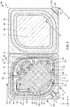
- FIGS. 1 to 3 are plan views schematically illustrating a spinal drainage kit container 100 according to the present embodiment.
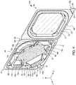
- FIGS. 4 and 5 are perspective views schematically illustrating the spinal drainage kit container 100 according to the present embodiment.
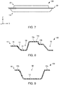
- FIGS. 6 and 7 are side views schematically illustrating the spinal drainage kit container 100 according to the present embodiment.
- an X-axis, a Y-axis, and a Z-axis are illustrated as three axes orthogonal to each other.
- the spinal drainage kit container 100 includes a container body 10, a lid 20, and a hinge 30.
- FIGS. 1 , 2 , 4 and 6 illustrate a state where the lid 20 of the spinal drainage kit container 100 is open. Further, FIGS. 3 , 5 and 7 illustrate a state where the lid 20 is closed. Furthermore, FIG. 1 illustrates a state where a spinal drainage kit 40 is disposed in the container body 10 of the spinal drainage kit container 100.
- a material for the container body 10 is, for example, plastic. Specifically, the material for the container body 10 is, for example, polyethylene terephthalate. The container body 10 is, for example, transparent.
- the spinal drainage kit container 100 is manufactured, for example, by injection molding.
- the container body 10 is provided with a recessed portion 11.
- the spinal drainage kit 40 is disposed in the recessed portion 11.
- the spinal drainage kit 40 includes, for example, a catheter 41, a puncture needle 42, a connector 43, a fixing pad 44, and a fixing seal 45.
- FIG. 8 is a cross-sectional view taken along an VIII-VIII line in FIG. 2 schematically illustrating the container body 10.
- the container body 10 has a bottom portion 12 and a side portion 13 that define the recessed portion 11.
- the side portion 13 is connected to an outer periphery of the bottom portion 12.
- the bottom portion 12 has a plane parallel to an XY plane.
- the bottom portion 12 has, for example, a first projecting portion 14a and a second projecting portion 14b.
- the first projecting portion 14a and the second projecting portion 14b have, for example, high portions 15a and low portions 15b.
- the height of the high portions 15a in a Z-axis direction is higher than that of the low portions 15b. That is, the high portions 15a are located in a +Z-axis direction relative to the low portions 15b.
- the height of the low portions 15b in the Z-axis direction is lower than that of the high portions 15a, and is higher than that of the bottom portion 12.
- the high portions 15a and the low portions 15b have planes parallel to the XY plane.
- the high portions 15a come into contact with a high-portion setting part 22 of the lid 20 in the state where the lid 20 is closed.
- the low portions 15b do not come into contact with the high-portion setting part 22 of the lid 20 in the state where the lid 20 is closed.
- the first projecting portion 14a defines a first chamber 50, a second chamber 52, and a third chamber 54.
- the catheter 41 is disposed in the first chamber 50.
- the puncture needle 42 is disposed in the second chamber 52.
- the connector 43 is disposed in the third chamber 54.
- the fixing pad 44 and the fixing seal 45 are also disposed in the third chamber 54.
- the first projecting portion 14a is located between the first chamber 50 and the second chamber 52, between the second chamber 52 and the third chamber 54, and between the first chamber 50 and the third chamber 54.
- the second projecting portion 14b defines the first chamber 50 and the second chamber 52.
- the second projecting portion 14b is located between the first chamber 50 and the second chamber 52.
- the first projecting portion 14a and the second projecting portion 14b define the first chamber 50 so that the first chamber 50 has an annular shape.
- the second chamber 52 and the third chamber 54 are surrounded by the first chamber 50.
- FIG. 9 is a cross-sectional view taken along a IX-IX line in FIG. 2 schematically illustrating the container body 10.
- the first projecting portion 14a and the second projecting portion 14b are separated from each other.
- the first chamber 50 and the second chamber 52 are connected to each other by first spaces 60 between the first projecting portion 14a and the second projecting portion 14b.
- the first projecting portion 14a is configured such that the second chamber 52 and the third chamber 54 are connected to each other by a second space 62.
- the first chamber 50 and the third chamber 54 are connected to each other through the first spaces 60, the second chamber 52, and the second space 62.
- the first chamber 50, the second chamber 52, and the third chamber 54 are connected to each other by the first spaces 60 and the second space 62 regardless of whether the lid 20 is in the state where the lid 20 is closed or the state where the lid 20 is open.
- the first chamber 50, the second chamber 52, and the third chamber 54 are connected to each other not only by the second space 62, but also by third spaces 64 defined by the low portions 15b.
- the bottom portion 12 may have a step.
- the height of the bottom portion 12 defining the first chamber 50 in the Z-axis direction may be higher than the height of the bottom portion 12 defining the second chamber 52 in the Z-axis direction.
- the container body 10 has a peripheral portion 16 and a first grip portion 17.
- the peripheral portion 16 is provided at a periphery of the recessed portion 11 in plan view.
- the peripheral portion 16 is connected to an end of the side portion 13 in the +Z-axis direction.
- the peripheral portion 16 is provided so as to surround the recessed portion 11 in plan view.
- FIG. 10 is a cross-sectional view taken along a X-X line in FIG. 2 schematically illustrating the container body 10.
- the peripheral portion 16 is provided with a groove 16a.
- the groove 16a enables communication between the first chamber 50 and an external space.
- the first chamber 50 and the external space are connected to each other by the groove 16a regardless of whether the lid 20 is in the state where the lid 20 is closed or the state where the lid 20 is open.
- the groove 16a is provided at a first corner 10a.
- the first grip portion 17 is connected to the peripheral portion 16.
- the first grip portion 17 is gripped when the lid 20 is to be opened.
- the first grip portion 17 is provided at the first corner 10a of the container body 10.
- the first corner 10a is a corner opposite to the hinge 30.
- the first corner 10a is an end of the container body 10 in a -X-axis direction and in a -Y-axis direction.
- the container body 10 has a substantially rectangular shape.
- the groove 16a is provided at the first corner 10a.
- the first grip portion 17 is located in a -Z-axis direction relative to the peripheral portion 16.
- the first grip portion 17 has a first protruding portion 18 that protrudes in a first direction.
- the first protruding portion 18 protrudes in the -Y-axis direction.
- the first protruding portion 18 does not overlap with the lid 20 in plan view in the state where the lid 20 is closed. That is, the first protruding portion 18 protrudes from the lid 20 in plan view in the state where the lid 20 is closed.
- FIG. 11 is a cross-sectional view taken along an XI-XI line in FIG. 2 schematically illustrating the lid 20.
- the lid 20 has a first ceiling portion 21, the high-portion setting part 22, a second ceiling portion 23, a contact portion 24, and a second grip portion 25.
- the first ceiling portion 21 defines the second chamber 52 and the third chamber 54 in the state where the lid 20 is closed.
- the first ceiling portion 21 faces, for example, the bottom portion 12 that defines the second chamber 52 and the third chamber 54.
- the high-portion setting part 22 is provided so as to surround the first ceiling portion 21 in plan view.
- the high portions 15a are disposed at the high-portion setting part 22 in the state where the lid 20 is closed.
- the high-portion setting part 22 comes into contact with the high portions 15a, for example, in the state where the lid 20 is closed.
- the second ceiling portion 23 is provided so as to surround the high-portion setting part 22 in plan view.
- the second ceiling portion 23 defines the first chamber 50 in the state where the lid 20 is closed.
- the second ceiling portion 23 faces, for example, the bottom portion 12 that defines the first chamber 50.
- the contact portion 24 is provided so as to surround the second ceiling portion 23 in plan view. The contact portion 24 comes into contact with the peripheral portion 16 in the state where the lid 20 is closed.
- the second grip portion 25 is connected to the contact portion 24.
- the second grip portion 25 is gripped when the lid 20 is to be opened.
- the second grip portion 25 is provided at a second corner 20a of the lid 20.
- the second corner 20a overlaps with the first corner 10a in plan view in the state where the lid 20 is closed.
- the second grip portion 25 is located in the -Z-axis direction relative to the contact portion 24.
- the groove 16a enables communication between the first chamber 50 and a space between the first grip portion 17 and the second grip portion 25.
- the second grip portion 25 has a second protruding portion 26 that protrudes in a second direction.
- the second direction is a direction orthogonal to the first direction, which is a direction in which the first protruding portion 18 protrudes.
- the second protruding portion 26 protrudes in a +X-axis direction.
- the second protruding portion 26 does not overlap with the container body 10 in plan view in the state where the lid 20 is closed. That is, the second protruding portion 26 protrudes from the container body 10 in plan view in the state where the lid 20 is closed.
- the hinge 30 connects the container body 10 and the lid 20.
- the lid 20 is movable about the hinge 30 as a rotation axis.
- the spinal drainage kit container 100 can be in the state where the lid 20 is open or the state where the lid 20 is closed.
- the hinge 30 extends in a Y-axis direction.
- the spinal drainage kit container 100 houses, for example, the catheter 41, the puncture needle 42, the connector 43, the fixing pad 44, and the fixing seal 45.
- the puncture needle 42 that includes an outer needle and a stylet.
- the stylet is removed from the outer needle of the puncture needle 42, and after confirming an outflow of cerebrospinal fluid, the catheter 41 is introduced into a living body using the outer needle as a guide.
- the puncture needle 42 is a needle for introducing the catheter 41 into the living body.
- the outer needle is removed while the catheter 41 is in place in the living body, and the connector 43 is connected to one end of the catheter 41.
- a drain tube (not illustrated) is connected to the connector 43 to drain the cerebrospinal fluid from the drain tube.
- the fixing pad 44 and the fixing seal 45 are used to fix the catheter 41.
- the puncture needle 42 may be housed in the spinal drainage kit container 100 in a state of being housed in a puncture needle container.
- the fixing pad 44 and the fixing seal 45 may be housed in the spinal drainage kit container 100 in a state of being housed in a sterilization bag that has been sterilized.
- the spinal drainage kit container 100 may be housed in a sterilization bag that has been sterilized.
- the sterilization bag may be filled with sterilization gas.
- a sterilization treatment may be performed on the spinal drainage kit container 100, and the first chamber 50, the second chamber 52, and the third chamber 54 may be filled with sterilization gas.
- the sterilization gas include, for example, ethylene oxide gas, and in this case, the sterilization treatment is an EOG (ethylene oxide gas) sterilization treatment.
- the spinal drainage kit container 100 has, for example, the following features.
- the spinal drainage kit container 100 includes the container body 10 provided with the recessed portion 11 in which the spinal drainage kit 40 that includes the catheter 41, the puncture needle 42 for introducing the catheter 41 into a living body, and the connector 43 that is connected to the catheter 41 are disposed, the lid 20, and the hinge 30 connecting the container body 10 and the lid 20.
- the container body 10 includes the peripheral portion 16 provided at the periphery of the recessed portion 11, and the first grip portion 17 that is connected to the peripheral portion 16 and is gripped when the lid 20 is to be opened.
- the first grip portion 17 is provided at the first corner 10a of the container body 10, which is opposite to the hinge 30.
- the first grip portion 17 has the first protruding portion 18 protruding in the first direction.
- the lid 20 includes the contact portion 24 that comes into contact with the peripheral portion 16 in the state where the lid 20 is closed, and the second grip portion 25 that is connected to the contact portion 24 and is gripped when the lid 20 is to be opened.
- the second grip portion 25 is provided at the second corner 20a that overlaps with the first corner 10a in plan view in the state where the lid 20 is closed.
- the second grip portion 25 has a second protruding portion 26 that protrudes in a second direction and does not overlap with the container body 10 in plan view in the state where the lid 20 is closed, and the second direction is orthogonal to the first direction.
- the lid 20 can be easily opened as compared with a case where the grip portion does not have a protruding portion.
- the lid 20 can be opened.
- the first grip portion 17 and the second grip portion 25 are separated from each other in the state where the lid 20 is closed. Therefore, in the spinal drainage kit container 100, the lid 20 can be easily opened as compared with a case where the first grip portion and the second grip portion are in contact with each other in the state where the lid is closed.
- the container body 10 has the bottom portion 12 that defines the recessed portion 11.
- the bottom portion 12 has the first projecting portion 14a that defines the first chamber 50 in which the catheter 41 is disposed, the second chamber 52 in which the puncture needle 42 is disposed, and the third chamber 54 in which the connector 43 is disposed. Therefore, for example, even when carrying the spinal drainage kit container 100 in which the spinal drainage kit 40 is housed, the catheter 41, the puncture needle 42, and the connector 43 can be disposed in the first chamber 50, the second chamber 52, and the third chamber 54, respectively.
- the spinal drainage kit container 100 the second chamber 52 and the third chamber 54 are surrounded by the first chamber 50 in plan view. Therefore, the spinal drainage kit container 100 can be decreased in size as compared with a case where the second chamber and the third chamber are not surrounded by the first chamber in plan view.
- the first chamber 50, the second chamber 52, and the third chamber 54 are connected to each other, and the groove 16a that enables communication between the first chamber 50 with the external space is provided at the peripheral portion 16. Therefore, in the spinal drainage kit container 100, sterilization gas can be introduced from the groove 16a in the state where the lid 20 is closed, thus the first chamber 50, the second chamber 52, and the third chamber 54 can be filled with the sterilization gas.
- the groove 16a is provided at the first corner 10a.
- the groove 16a serving as an introduction port for the sterilization gas can be easily found.
- the material for the container body 10 and the lid 20 is plastic. Therefore, the spinal drainage kit container 100 can be formed by injection molding.
- the invention includes configurations that are substantially the same as the configurations described in the embodiments.
- Substantially same configurations means configurations that are the same in function, method, and results, or configurations that are the same in objective and effects, for example.
- the invention also includes configurations in which non-essential elements described in the embodiments are replaced by other elements.
- the invention also includes configurations having the same effects as those of the configurations described in the embodiments, or configurations capable of achieving the same objectives as those of the configurations described in the embodiments.
- the invention further includes configurations obtained by adding known art to the configurations described in the embodiments.
Landscapes
- Health & Medical Sciences (AREA)
- Engineering & Computer Science (AREA)
- Life Sciences & Earth Sciences (AREA)
- Heart & Thoracic Surgery (AREA)
- Animal Behavior & Ethology (AREA)
- Biomedical Technology (AREA)
- General Health & Medical Sciences (AREA)
- Public Health (AREA)
- Veterinary Medicine (AREA)
- Surgery (AREA)
- Anesthesiology (AREA)
- Hematology (AREA)
- Mechanical Engineering (AREA)
- Medical Informatics (AREA)
- Nuclear Medicine, Radiotherapy & Molecular Imaging (AREA)
- Molecular Biology (AREA)
- Otolaryngology (AREA)
- Chemical & Material Sciences (AREA)
- Ceramic Engineering (AREA)
- Composite Materials (AREA)
- Vascular Medicine (AREA)
- Biophysics (AREA)
- Pulmonology (AREA)
- Media Introduction/Drainage Providing Device (AREA)
- External Artificial Organs (AREA)
- Medical Preparation Storing Or Oral Administration Devices (AREA)
Abstract
Description
- The present invention relates to a spinal drainage kit container.
- Spinal drainage is a method in which a catheter is placed in a spinal subarachnoid space and spinal fluid and the like are drained out of the body for the purpose of improving pathological conditions such as a subarachnoid hemorrhage.
- For example, Patent Literature 1 describes a method for harvesting bone marrow, comprising steps of forming a hole in cortical bone, inserting a flexible catheter into the hole, and aspirating bone marrow through the catheter.
- PTL 1:
WO 2005/96952 - A spinal drainage kit used for the spinal drainage as described above is housed in a container. The container in which the spinal drainage kit is housed is preferably easy to open.
- A spinal drainage kit container according to the invention includes:
- a container body provided with a recessed portion in which a spinal drainage kit that includes a catheter, a puncture needle for introducing the catheter into a living body, and a connector that is connected to the catheter is disposed;
- a lid; and
- a hinge connecting the container body and the lid,
- the container body including a peripheral portion provided at a periphery of the recessed portion, and a first grip portion that is connected to the peripheral portion and is gripped when the lid is to be opened;
- the first grip portion being provided at a first corner of the container body, which is opposite to the hinge;
- the first grip portion having a first protruding portion protruding in a first direction;
- the lid including a contact portion that comes into contact with the peripheral portion in a state where the lid is closed, and a second grip portion that is connected to the contact portion and is gripped when the lid is to be opened;
- the second grip portion being provided at a second corner of the lid, which overlaps with the first corner in plan view in the state where the lid is closed; and
- the second grip portion having a second protruding portion that protrudes in a second direction and does not overlap with the container body in plan view in the state where the lid is closed, the second direction being orthogonal to the first direction.
- According to one aspect of the spinal drainage kit container, the first grip portion and the second grip portion may be separated from each other in the state where the lid is closed.
- According to one aspect of the spinal drainage kit container, the container body may have a bottom portion that defines the recessed portion, and the bottom portion may have a projecting portion that defines a first chamber in which the catheter is disposed, a second chamber in which the puncture needle is disposed, and a third chamber in which the connector is disposed.
- According to one aspect of the spinal drainage kit container, the second chamber and the third chamber may be surrounded by the first chamber in plan view.
- According to one aspect of the spinal drainage kit container, the first chamber, the second chamber, and the third chamber may be connected to each other, and a groove that enables communication between the first chamber and an external space may be provided at the peripheral portion.
- According to one aspect of the spinal drainage kit container, the groove may be provided at the first corner.
- According to one aspect of the spinal drainage kit container, a material for the container body and the lid may be plastic.
-
-
FIG. 1 is a plan view schematically illustrating a spinal drainage kit container according to the present embodiment. -
FIG. 2 is a plan view schematically illustrating the spinal drainage kit container according to the present embodiment. -
FIG. 3 is a plan view schematically illustrating the spinal drainage kit container according to the present embodiment. -
FIG. 4 is a perspective view schematically illustrating the spinal drainage kit container according to the present embodiment. -
FIG. 5 is a perspective view schematically illustrating the spinal drainage kit container according to the present embodiment. -
FIG. 6 is a side view schematically illustrating the spinal drainage kit container according to the present embodiment. -
FIG. 7 is a side view schematically illustrating the spinal drainage kit container according to the present embodiment. -
FIG. 8 is a cross-sectional view schematically illustrating the spinal drainage kit container according to the present embodiment. -
FIG. 9 is a cross-sectional view schematically illustrating the spinal drainage kit container according to the present embodiment. -
FIG. 10 is a cross-sectional view schematically illustrating the spinal drainage kit container according to the present embodiment. -
FIG. 11 is a cross-sectional view schematically illustrating the spinal drainage kit container according to the present embodiment. - Preferred embodiments of the invention are described in detail below with reference to the drawings. It is noted that the following embodiments do not unduly limit the scope of the invention as stated in the claims. In addition, all of the elements described in the following embodiments are not necessarily essential requirements of the invention.
- A configuration of a spinal drainage kit container according to a present embodiment will be described with reference to the drawings.
FIGS. 1 to 3 are plan views schematically illustrating a spinaldrainage kit container 100 according to the present embodiment.FIGS. 4 and5 are perspective views schematically illustrating the spinaldrainage kit container 100 according to the present embodiment.FIGS. 6 and7 are side views schematically illustrating the spinaldrainage kit container 100 according to the present embodiment. InFIGS. 1 to 7 , an X-axis, a Y-axis, and a Z-axis are illustrated as three axes orthogonal to each other. - As illustrated in
FIGS. 1 to 7 , the spinaldrainage kit container 100 includes acontainer body 10, alid 20, and ahinge 30. -
FIGS. 1 ,2 ,4 and6 illustrate a state where thelid 20 of the spinaldrainage kit container 100 is open. Further,FIGS. 3 ,5 and7 illustrate a state where thelid 20 is closed. Furthermore,FIG. 1 illustrates a state where aspinal drainage kit 40 is disposed in thecontainer body 10 of the spinaldrainage kit container 100. - A material for the
container body 10 is, for example, plastic. Specifically, the material for thecontainer body 10 is, for example, polyethylene terephthalate. Thecontainer body 10 is, for example, transparent. The spinaldrainage kit container 100 is manufactured, for example, by injection molding. - As illustrated in
FIG. 1 , thecontainer body 10 is provided with a recessedportion 11. Thespinal drainage kit 40 is disposed in the recessedportion 11. Thespinal drainage kit 40 includes, for example, acatheter 41, apuncture needle 42, aconnector 43, afixing pad 44, and afixing seal 45. Here,FIG. 8 is a cross-sectional view taken along an VIII-VIII line inFIG. 2 schematically illustrating thecontainer body 10. - As illustrated in
FIGS. 2 and8 , thecontainer body 10 has abottom portion 12 and aside portion 13 that define therecessed portion 11. Theside portion 13 is connected to an outer periphery of thebottom portion 12. In an example illustrated inFIG. 2 , thebottom portion 12 has a plane parallel to an XY plane. - The
bottom portion 12 has, for example, a first projectingportion 14a and a second projectingportion 14b. The first projectingportion 14a and the second projectingportion 14b have, for example,high portions 15a andlow portions 15b. The height of thehigh portions 15a in a Z-axis direction is higher than that of thelow portions 15b. That is, thehigh portions 15a are located in a +Z-axis direction relative to thelow portions 15b. The height of thelow portions 15b in the Z-axis direction is lower than that of thehigh portions 15a, and is higher than that of thebottom portion 12. In the illustrated example, thehigh portions 15a and thelow portions 15b have planes parallel to the XY plane. Thehigh portions 15a come into contact with a high-portion setting part 22 of thelid 20 in the state where thelid 20 is closed. Thelow portions 15b do not come into contact with the high-portion setting part 22 of thelid 20 in the state where thelid 20 is closed. - The first projecting
portion 14a defines afirst chamber 50, asecond chamber 52, and athird chamber 54. Thecatheter 41 is disposed in thefirst chamber 50. Thepuncture needle 42 is disposed in thesecond chamber 52. Theconnector 43 is disposed in thethird chamber 54. In the illustrated example, the fixingpad 44 and the fixingseal 45 are also disposed in thethird chamber 54. The first projectingportion 14a is located between thefirst chamber 50 and thesecond chamber 52, between thesecond chamber 52 and thethird chamber 54, and between thefirst chamber 50 and thethird chamber 54. The second projectingportion 14b defines thefirst chamber 50 and thesecond chamber 52. The second projectingportion 14b is located between thefirst chamber 50 and thesecond chamber 52. - The first projecting
portion 14a and the second projectingportion 14b define thefirst chamber 50 so that thefirst chamber 50 has an annular shape. In a plan view (viewed from the Z-axis direction), thesecond chamber 52 and thethird chamber 54 are surrounded by thefirst chamber 50. Here,FIG. 9 is a cross-sectional view taken along a IX-IX line inFIG. 2 schematically illustrating thecontainer body 10. - As illustrated in
FIGS. 2 and9 , the first projectingportion 14a and the second projectingportion 14b are separated from each other. Thefirst chamber 50 and thesecond chamber 52 are connected to each other byfirst spaces 60 between the first projectingportion 14a and the second projectingportion 14b. As illustrated inFIG. 2 , the first projectingportion 14a is configured such that thesecond chamber 52 and thethird chamber 54 are connected to each other by asecond space 62. Thefirst chamber 50 and thethird chamber 54 are connected to each other through thefirst spaces 60, thesecond chamber 52, and thesecond space 62. As described above, thefirst chamber 50, thesecond chamber 52, and thethird chamber 54 are connected to each other by thefirst spaces 60 and thesecond space 62 regardless of whether thelid 20 is in the state where thelid 20 is closed or the state where thelid 20 is open. - In the illustrated example, in the state where the
lid 20 is closed, thefirst chamber 50, thesecond chamber 52, and thethird chamber 54 are connected to each other not only by thesecond space 62, but also bythird spaces 64 defined by thelow portions 15b. - Further, although not illustrated, the
bottom portion 12 may have a step. For example, the height of thebottom portion 12 defining thefirst chamber 50 in the Z-axis direction may be higher than the height of thebottom portion 12 defining thesecond chamber 52 in the Z-axis direction. - The
container body 10 has aperipheral portion 16 and afirst grip portion 17. Theperipheral portion 16 is provided at a periphery of the recessedportion 11 in plan view. In the illustrated example, theperipheral portion 16 is connected to an end of theside portion 13 in the +Z-axis direction. Theperipheral portion 16 is provided so as to surround the recessedportion 11 in plan view. Here,FIG. 10 is a cross-sectional view taken along a X-X line inFIG. 2 schematically illustrating thecontainer body 10. - As illustrated in
FIGS. 2 and10 , theperipheral portion 16 is provided with agroove 16a. Thegroove 16a enables communication between thefirst chamber 50 and an external space. Thefirst chamber 50 and the external space are connected to each other by thegroove 16a regardless of whether thelid 20 is in the state where thelid 20 is closed or the state where thelid 20 is open. In the example illustrated inFIG. 2 , thegroove 16a is provided at afirst corner 10a. - The
first grip portion 17 is connected to theperipheral portion 16. Thefirst grip portion 17 is gripped when thelid 20 is to be opened. Thefirst grip portion 17 is provided at thefirst corner 10a of thecontainer body 10. Thefirst corner 10a is a corner opposite to thehinge 30. In the illustrated example, thefirst corner 10a is an end of thecontainer body 10 in a -X-axis direction and in a -Y-axis direction. Thecontainer body 10 has a substantially rectangular shape. Thegroove 16a is provided at thefirst corner 10a. Thefirst grip portion 17 is located in a -Z-axis direction relative to theperipheral portion 16. - The
first grip portion 17 has a first protrudingportion 18 that protrudes in a first direction. In the example illustrated inFIG. 2 , the first protrudingportion 18 protrudes in the -Y-axis direction. The first protrudingportion 18 does not overlap with thelid 20 in plan view in the state where thelid 20 is closed. That is, the first protrudingportion 18 protrudes from thelid 20 in plan view in the state where thelid 20 is closed. - The
lid 20 is connected to thecontainer body 10 via thehinge 30. A material for thelid 20 is the same as that for thecontainer body 10. Here,FIG. 11 is a cross-sectional view taken along an XI-XI line inFIG. 2 schematically illustrating thelid 20. - As illustrated in
FIGS. 2 and11 , thelid 20 has afirst ceiling portion 21, the high-portion setting part 22, asecond ceiling portion 23, acontact portion 24, and asecond grip portion 25. - The
first ceiling portion 21 defines thesecond chamber 52 and thethird chamber 54 in the state where thelid 20 is closed. Thefirst ceiling portion 21 faces, for example, thebottom portion 12 that defines thesecond chamber 52 and thethird chamber 54. - The high-
portion setting part 22 is provided so as to surround thefirst ceiling portion 21 in plan view. Thehigh portions 15a are disposed at the high-portion setting part 22 in the state where thelid 20 is closed. The high-portion setting part 22 comes into contact with thehigh portions 15a, for example, in the state where thelid 20 is closed. - The
second ceiling portion 23 is provided so as to surround the high-portion setting part 22 in plan view. Thesecond ceiling portion 23 defines thefirst chamber 50 in the state where thelid 20 is closed. Thesecond ceiling portion 23 faces, for example, thebottom portion 12 that defines thefirst chamber 50. - The
contact portion 24 is provided so as to surround thesecond ceiling portion 23 in plan view. Thecontact portion 24 comes into contact with theperipheral portion 16 in the state where thelid 20 is closed. - The
second grip portion 25 is connected to thecontact portion 24. Thesecond grip portion 25 is gripped when thelid 20 is to be opened. Thesecond grip portion 25 is provided at asecond corner 20a of thelid 20. Thesecond corner 20a overlaps with thefirst corner 10a in plan view in the state where thelid 20 is closed. In the example illustrated inFIG. 2 , thesecond grip portion 25 is located in the -Z-axis direction relative to thecontact portion 24. In the state where thelid 20 is closed, thefirst grip portion 17 and thesecond grip portion 25 are separated from each other. Thegroove 16a enables communication between thefirst chamber 50 and a space between thefirst grip portion 17 and thesecond grip portion 25. - The
second grip portion 25 has a second protrudingportion 26 that protrudes in a second direction. The second direction is a direction orthogonal to the first direction, which is a direction in which the first protrudingportion 18 protrudes. In the example illustrated inFIG. 2 , the second protrudingportion 26 protrudes in a +X-axis direction. The second protrudingportion 26 does not overlap with thecontainer body 10 in plan view in the state where thelid 20 is closed. That is, the second protrudingportion 26 protrudes from thecontainer body 10 in plan view in the state where thelid 20 is closed. - The
hinge 30 connects thecontainer body 10 and thelid 20. Thelid 20 is movable about thehinge 30 as a rotation axis. As a result, the spinaldrainage kit container 100 can be in the state where thelid 20 is open or the state where thelid 20 is closed. In the illustrated example, thehinge 30 extends in a Y-axis direction. - As illustrated in
FIG. 1 , the spinaldrainage kit container 100 houses, for example, thecatheter 41, thepuncture needle 42, theconnector 43, the fixingpad 44, and the fixingseal 45. - When performing spinal drainage, first, lumbar puncture is performed using the
puncture needle 42 that includes an outer needle and a stylet. Next, the stylet is removed from the outer needle of thepuncture needle 42, and after confirming an outflow of cerebrospinal fluid, thecatheter 41 is introduced into a living body using the outer needle as a guide. Thepuncture needle 42 is a needle for introducing thecatheter 41 into the living body. Next, the outer needle is removed while thecatheter 41 is in place in the living body, and theconnector 43 is connected to one end of thecatheter 41. Then, a drain tube (not illustrated) is connected to theconnector 43 to drain the cerebrospinal fluid from the drain tube. The fixingpad 44 and the fixingseal 45 are used to fix thecatheter 41. - Although not illustrated, the
puncture needle 42 may be housed in the spinaldrainage kit container 100 in a state of being housed in a puncture needle container. Further, although not illustrated, the fixingpad 44 and the fixingseal 45 may be housed in the spinaldrainage kit container 100 in a state of being housed in a sterilization bag that has been sterilized. - Although not illustrated, the spinal
drainage kit container 100 may be housed in a sterilization bag that has been sterilized. The sterilization bag may be filled with sterilization gas. A sterilization treatment may be performed on the spinaldrainage kit container 100, and thefirst chamber 50, thesecond chamber 52, and thethird chamber 54 may be filled with sterilization gas. Examples of the sterilization gas include, for example, ethylene oxide gas, and in this case, the sterilization treatment is an EOG (ethylene oxide gas) sterilization treatment. - The spinal
drainage kit container 100 has, for example, the following features. - The spinal
drainage kit container 100 includes thecontainer body 10 provided with the recessedportion 11 in which thespinal drainage kit 40 that includes thecatheter 41, thepuncture needle 42 for introducing thecatheter 41 into a living body, and theconnector 43 that is connected to thecatheter 41 are disposed, thelid 20, and thehinge 30 connecting thecontainer body 10 and thelid 20. - Further, in the spinal
drainage kit container 100, thecontainer body 10 includes theperipheral portion 16 provided at the periphery of the recessedportion 11, and thefirst grip portion 17 that is connected to theperipheral portion 16 and is gripped when thelid 20 is to be opened. Thefirst grip portion 17 is provided at thefirst corner 10a of thecontainer body 10, which is opposite to thehinge 30. Thefirst grip portion 17 has the first protrudingportion 18 protruding in the first direction. - Furthermore, in the spinal
drainage kit container 100, thelid 20 includes thecontact portion 24 that comes into contact with theperipheral portion 16 in the state where thelid 20 is closed, and thesecond grip portion 25 that is connected to thecontact portion 24 and is gripped when thelid 20 is to be opened. Thesecond grip portion 25 is provided at thesecond corner 20a that overlaps with thefirst corner 10a in plan view in the state where thelid 20 is closed. Thesecond grip portion 25 has a second protrudingportion 26 that protrudes in a second direction and does not overlap with thecontainer body 10 in plan view in the state where thelid 20 is closed, and the second direction is orthogonal to the first direction. - Therefore, in the spinal
drainage kit container 100, thelid 20 can be easily opened as compared with a case where the grip portion does not have a protruding portion. In the spinaldrainage kit container 100, for example, by gripping the first protrudingportion 18 of thefirst grip portion 17 with the thumb and index finger of the right hand, and by gripping the second protrudingportion 26 of thesecond grip portion 25 with the thumb and index finger of the left hand, thelid 20 can be opened. - In the spinal
drainage kit container 100, thefirst grip portion 17 and thesecond grip portion 25 are separated from each other in the state where thelid 20 is closed. Therefore, in the spinaldrainage kit container 100, thelid 20 can be easily opened as compared with a case where the first grip portion and the second grip portion are in contact with each other in the state where the lid is closed. - In the spinal
drainage kit container 100, thecontainer body 10 has thebottom portion 12 that defines the recessedportion 11. Thebottom portion 12 has the first projectingportion 14a that defines thefirst chamber 50 in which thecatheter 41 is disposed, thesecond chamber 52 in which thepuncture needle 42 is disposed, and thethird chamber 54 in which theconnector 43 is disposed. Therefore, for example, even when carrying the spinaldrainage kit container 100 in which thespinal drainage kit 40 is housed, thecatheter 41, thepuncture needle 42, and theconnector 43 can be disposed in thefirst chamber 50, thesecond chamber 52, and thethird chamber 54, respectively. - In the spinal
drainage kit container 100, thesecond chamber 52 and thethird chamber 54 are surrounded by thefirst chamber 50 in plan view. Therefore, the spinaldrainage kit container 100 can be decreased in size as compared with a case where the second chamber and the third chamber are not surrounded by the first chamber in plan view. - In the spinal
drainage kit container 100, thefirst chamber 50, thesecond chamber 52, and thethird chamber 54 are connected to each other, and thegroove 16a that enables communication between thefirst chamber 50 with the external space is provided at theperipheral portion 16. Therefore, in the spinaldrainage kit container 100, sterilization gas can be introduced from thegroove 16a in the state where thelid 20 is closed, thus thefirst chamber 50, thesecond chamber 52, and thethird chamber 54 can be filled with the sterilization gas. - In the spinal
drainage kit container 100, thegroove 16a is provided at thefirst corner 10a. In the spinaldrainage kit container 100, since the first protrudingportion 18 is provided at thefirst corner 10a, thegroove 16a serving as an introduction port for the sterilization gas can be easily found. - In the spinal
drainage kit container 100, the material for thecontainer body 10 and thelid 20 is plastic. Therefore, the spinaldrainage kit container 100 can be formed by injection molding. - The invention is not limited to the above-described embodiments, and various modifications can be made. For example, the invention includes configurations that are substantially the same as the configurations described in the embodiments. Substantially same configurations means configurations that are the same in function, method, and results, or configurations that are the same in objective and effects, for example. The invention also includes configurations in which non-essential elements described in the embodiments are replaced by other elements. The invention also includes configurations having the same effects as those of the configurations described in the embodiments, or configurations capable of achieving the same objectives as those of the configurations described in the embodiments. The invention further includes configurations obtained by adding known art to the configurations described in the embodiments.
-
- 10
- Container body
- 10a
- First corner
- 11
- Recessed portion
- 12
- Bottom portion
- 13
- Side portion
- 14a
- First projecting portion
- 14b
- Second projecting portion
- 15a
- High portion
- 15b
- Low portion
- 16
- Peripheral portion
- 16a
- Groove
- 17
- First grip portion
- 18
- First protruding portion
- 20
- Lid
- 20a
- Second corner
- 21
- First ceiling portion
- 22
- High-portion setting part
- 23
- Second ceiling portion
- 24
- Contact portion
- 25
- Second grip portion
- 26
- Second protruding portion
- 30
- Hinge
- 40
- Spinal drainage kit
- 41
- Catheter
- 42
- Puncture needle
- 43
- Connector
- 44
- Fixing pad
- 45
- Fixing seal
- 50
- First chamber
- 52
- Second chamber
- 54
- Third chamber
- 60
- First space
- 62
- Second space
- 64
- Third space
- 100
- Spinal drainage kit container
Claims (7)
- A spinal drainage kit container comprising:a container body provided with a recessed portion in which a spinal drainage kit that includes a catheter, a puncture needle for introducing the catheter into a living body, and a connector that is connected to the catheter is disposed;a lid; anda hinge connecting the container body and the lid,the container body including a peripheral portion provided at a periphery of the recessed portion, and a first grip portion that is connected to the peripheral portion and is gripped when the lid is to be opened;the first grip portion being provided at a first corner of the container body, which is opposite to the hinge;the first grip portion having a first protruding portion protruding in a first direction;the lid including a contact portion that comes into contact with the peripheral portion in a state where the lid is closed, and a second grip portion that is connected to the contact portion and is gripped when the lid is to be opened;the second grip portion being provided at a second corner of the lid, which overlaps with the first corner in plan view in the state where the lid is closed; andthe second grip portion having a second protruding portion that protrudes in a second direction and does not overlap with the container body in plan view in the state where the lid is closed, the second direction being orthogonal to the first direction.
- The spinal drainage kit container according to claim 1, wherein
the first grip portion and the second grip portion are separated from each other in the state where the lid is closed. - The spinal drainage kit container according to claim 1 or 2, whereinthe container body has a bottom portion that defines the recessed portion, andthe bottom portion has a projecting portion that defines a first chamber in which the catheter is disposed, a second chamber in which the puncture needle is disposed, and a third chamber in which the connector is disposed.
- The spinal drainage kit container according to claim 3, wherein
the second chamber and the third chamber are surrounded by the first chamber in plan view. - The spinal drainage kit container according to claim 4, whereinthe first chamber, the second chamber, and the third chamber are connected to each other, anda groove that enables communication between the first chamber and an external space is provided at the peripheral portion.
- The spinal drainage kit container according to claim 5, wherein the groove is provided at the first corner.
- The spinal drainage kit container according to any one of claims 1 to 6, wherein a material for the container body and the lid is plastic.
Applications Claiming Priority (2)
| Application Number | Priority Date | Filing Date | Title |
|---|---|---|---|
| JP2018004349U JP3219813U (en) | 2018-11-09 | 2018-11-09 | Spinal Retention Kit Container |
| PCT/JP2019/040387 WO2020095628A1 (en) | 2018-11-09 | 2019-10-15 | Container for spinal drainage kit |
Publications (3)
| Publication Number | Publication Date |
|---|---|
| EP3878766A1 true EP3878766A1 (en) | 2021-09-15 |
| EP3878766A4 EP3878766A4 (en) | 2021-12-29 |
| EP3878766B1 EP3878766B1 (en) | 2024-02-14 |
Family
ID=65036989
Family Applications (1)
| Application Number | Title | Priority Date | Filing Date |
|---|---|---|---|
| EP19881246.3A Active EP3878766B1 (en) | 2018-11-09 | 2019-10-15 | Container for spinal drainage kit |
Country Status (4)
| Country | Link |
|---|---|
| US (1) | US12239805B2 (en) |
| EP (1) | EP3878766B1 (en) |
| JP (1) | JP3219813U (en) |
| WO (1) | WO2020095628A1 (en) |
Family Cites Families (20)
| Publication number | Priority date | Publication date | Assignee | Title |
|---|---|---|---|---|
| CA2112396A1 (en) * | 1991-07-01 | 1993-01-21 | Anthony James Murray Garwood | Improved packaging with peelable lid |
| WO1994008642A1 (en) | 1992-10-08 | 1994-04-28 | Abbott Laboratories | Laparoscopic jejunostomy instrumentation kit |
| JP2003128106A (en) * | 2001-10-22 | 2003-05-08 | Nikko Kaihatsu Kk | Egg container |
| US20030150770A1 (en) * | 2002-02-13 | 2003-08-14 | Berkley Industries Llc | Chip clamshell packaging |
| US20050109772A1 (en) * | 2003-11-21 | 2005-05-26 | Thorpe Charles C. | Microwaveable cooking apparatus, product and method of preparing microwaved food item |
| US20090187116A1 (en) | 2004-04-05 | 2009-07-23 | Yasuharu Noishiki | Method for harvesting bone marrow and its medical apparatus |
| JP4370230B2 (en) * | 2004-09-08 | 2009-11-25 | 株式会社カネカメディックス | Medical tubing and shunt system |
| US7624859B1 (en) * | 2008-06-25 | 2009-12-01 | Eveready Battery Co., Inc. | Self-standing active foot for blister packaging |
| US20110031154A1 (en) * | 2009-08-07 | 2011-02-10 | Peter Overgaag | Container for produce storage, packing & transport |
| JP5753707B2 (en) * | 2011-03-09 | 2015-07-22 | ダイセルパックシステムズ株式会社 | Packaging container |
| CN202538022U (en) | 2011-11-30 | 2012-11-21 | 卢天喜 | Disposable neural canal drainage kit |
| US9545459B2 (en) | 2012-03-31 | 2017-01-17 | Depuy Ireland Unlimited Company | Container for surgical instruments and system including same |
| US8662306B2 (en) * | 2012-04-04 | 2014-03-04 | Cook Medical Technologies Llc | Universal catheter tray assembly |
| US9586746B2 (en) * | 2012-06-11 | 2017-03-07 | Sfc Global Supply Chain, Inc. | Microwave package for single-step cooking of multi-component foodstuffs |
| WO2014049800A1 (en) * | 2012-09-27 | 2014-04-03 | テルモ・クリニカルサプライ株式会社 | Sterilized medical kit package |
| US20140110296A1 (en) * | 2012-10-19 | 2014-04-24 | Medtronic Ardian Luxembourg S.A.R.L. | Packaging for Catheter Treatment Devices and Associated Devices, Systems, and Methods |
| JP6591943B2 (en) * | 2016-08-30 | 2019-10-16 | 株式会社ユニシス | Catheter connector |
| US10279962B2 (en) * | 2017-03-21 | 2019-05-07 | Display Pack, Inc. | Tamper-evident thermoformed packaging |
| US20200055642A1 (en) * | 2018-08-17 | 2020-02-20 | Easypak Llc | Container with tamper-evident closure |
| US20210130060A1 (en) * | 2019-11-04 | 2021-05-06 | Display Pack, Inc. | Thermoformed bakery package |
-
2018
- 2018-11-09 JP JP2018004349U patent/JP3219813U/en active Active
-
2019
- 2019-10-15 WO PCT/JP2019/040387 patent/WO2020095628A1/en not_active Ceased
- 2019-10-15 US US17/291,108 patent/US12239805B2/en active Active
- 2019-10-15 EP EP19881246.3A patent/EP3878766B1/en active Active
Also Published As
| Publication number | Publication date |
|---|---|
| US20220001155A1 (en) | 2022-01-06 |
| WO2020095628A1 (en) | 2020-05-14 |
| EP3878766A4 (en) | 2021-12-29 |
| JP3219813U (en) | 2019-01-24 |
| EP3878766B1 (en) | 2024-02-14 |
| US12239805B2 (en) | 2025-03-04 |
Similar Documents
| Publication | Publication Date | Title |
|---|---|---|
| EP3127503B1 (en) | Sterile case for electronic devices used in medical procedures | |
| US11083867B2 (en) | Storage case | |
| US20070295620A1 (en) | Medical Package, a Medical Container, a Medical Package System and Methods for Removal of a Medical Component from a Container | |
| AU2014342252B2 (en) | Wire management feature integrated into PETG tray for EM trackable disposable products | |
| EP2646158A1 (en) | Specimen collection container assembly | |
| US20080226507A1 (en) | Disinfection system | |
| EP3878766B1 (en) | Container for spinal drainage kit | |
| BR112019023374A2 (en) | inner container protection device | |
| JP2023504180A (en) | Body fluid observation equipment | |
| US20250017502A1 (en) | Closure for a Biological Fluid Collection Device | |
| CN106725875A (en) | The aseptic insulation blocking sleeve of operating theater instruments | |
| EP3669931B1 (en) | Storage container, packaging member, and medical instrument set | |
| WO2014049800A1 (en) | Sterilized medical kit package | |
| JP7040454B2 (en) | container | |
| KR102470260B1 (en) | Body fluid monitoring device | |
| De Falco et al. | Design and fabrication of an elastomeric unit for soft modular robots in minimally invasive surgery | |
| CA2544987A1 (en) | Specimen filter container having data storage | |
| WO2018132081A1 (en) | Endoscopic suture device with circular needle | |
| EP3984901A1 (en) | Medical container | |
| EP4541309A1 (en) | Cleaning instrument for surgical instrument | |
| CN223944677U (en) | Instrument sterilization box of autoclave | |
| CN211122886U (en) | Containing device of blood gas testing component and blood gas testing device | |
| CN205252046U (en) | Acupuncture needle box | |
| JP2005126133A (en) | Medical packaging materials | |
| WO2025054955A1 (en) | Monitoring apparatus and electron beam irradiation sterilization apparatus |
Legal Events
| Date | Code | Title | Description |
|---|---|---|---|
| STAA | Information on the status of an ep patent application or granted ep patent |
Free format text: STATUS: THE INTERNATIONAL PUBLICATION HAS BEEN MADE |
|
| PUAI | Public reference made under article 153(3) epc to a published international application that has entered the european phase |
Free format text: ORIGINAL CODE: 0009012 |
|
| STAA | Information on the status of an ep patent application or granted ep patent |
Free format text: STATUS: REQUEST FOR EXAMINATION WAS MADE |
|
| 17P | Request for examination filed |
Effective date: 20210430 |
|
| AK | Designated contracting states |
Kind code of ref document: A1 Designated state(s): AL AT BE BG CH CY CZ DE DK EE ES FI FR GB GR HR HU IE IS IT LI LT LU LV MC MK MT NL NO PL PT RO RS SE SI SK SM TR |
|
| A4 | Supplementary search report drawn up and despatched |
Effective date: 20211129 |
|
| RIC1 | Information provided on ipc code assigned before grant |
Ipc: A61M 1/00 20060101ALN20211123BHEP Ipc: A61M 25/00 20060101ALN20211123BHEP Ipc: A61B 50/20 20160101ALI20211123BHEP Ipc: A61B 50/30 20160101AFI20211123BHEP |
|
| DAV | Request for validation of the european patent (deleted) | ||
| DAX | Request for extension of the european patent (deleted) | ||
| REG | Reference to a national code |
Ref country code: DE Ref legal event code: R079 Free format text: PREVIOUS MAIN CLASS: B65D0075320000 Ipc: A61B0050300000 Ref document number: 602019046702 Country of ref document: DE |
|
| GRAP | Despatch of communication of intention to grant a patent |
Free format text: ORIGINAL CODE: EPIDOSNIGR1 |
|
| STAA | Information on the status of an ep patent application or granted ep patent |
Free format text: STATUS: GRANT OF PATENT IS INTENDED |
|
| RIC1 | Information provided on ipc code assigned before grant |
Ipc: A61M 1/00 20060101ALN20230814BHEP Ipc: A61M 25/00 20060101ALN20230814BHEP Ipc: A61B 50/20 20160101ALI20230814BHEP Ipc: A61B 50/30 20160101AFI20230814BHEP |
|
| INTG | Intention to grant announced |
Effective date: 20230911 |
|
| GRAS | Grant fee paid |
Free format text: ORIGINAL CODE: EPIDOSNIGR3 |
|
| GRAA | (expected) grant |
Free format text: ORIGINAL CODE: 0009210 |
|
| STAA | Information on the status of an ep patent application or granted ep patent |
Free format text: STATUS: THE PATENT HAS BEEN GRANTED |
|
| AK | Designated contracting states |
Kind code of ref document: B1 Designated state(s): AL AT BE BG CH CY CZ DE DK EE ES FI FR GB GR HR HU IE IS IT LI LT LU LV MC MK MT NL NO PL PT RO RS SE SI SK SM TR |
|
| REG | Reference to a national code |
Ref country code: GB Ref legal event code: FG4D |
|
| REG | Reference to a national code |
Ref country code: CH Ref legal event code: EP |
|
| REG | Reference to a national code |
Ref country code: DE Ref legal event code: R096 Ref document number: 602019046702 Country of ref document: DE |
|
| REG | Reference to a national code |
Ref country code: IE Ref legal event code: FG4D |
|
| REG | Reference to a national code |
Ref country code: LT Ref legal event code: MG9D |
|
| REG | Reference to a national code |
Ref country code: NL Ref legal event code: MP Effective date: 20240214 |
|
| PG25 | Lapsed in a contracting state [announced via postgrant information from national office to epo] |
Ref country code: IS Free format text: LAPSE BECAUSE OF FAILURE TO SUBMIT A TRANSLATION OF THE DESCRIPTION OR TO PAY THE FEE WITHIN THE PRESCRIBED TIME-LIMIT Effective date: 20240614 |
|
| PG25 | Lapsed in a contracting state [announced via postgrant information from national office to epo] |
Ref country code: LT Free format text: LAPSE BECAUSE OF FAILURE TO SUBMIT A TRANSLATION OF THE DESCRIPTION OR TO PAY THE FEE WITHIN THE PRESCRIBED TIME-LIMIT Effective date: 20240214 |
|
| PG25 | Lapsed in a contracting state [announced via postgrant information from national office to epo] |
Ref country code: GR Free format text: LAPSE BECAUSE OF FAILURE TO SUBMIT A TRANSLATION OF THE DESCRIPTION OR TO PAY THE FEE WITHIN THE PRESCRIBED TIME-LIMIT Effective date: 20240515 |
|
| REG | Reference to a national code |
Ref country code: AT Ref legal event code: MK05 Ref document number: 1656395 Country of ref document: AT Kind code of ref document: T Effective date: 20240214 |
|
| PG25 | Lapsed in a contracting state [announced via postgrant information from national office to epo] |
Ref country code: HR Free format text: LAPSE BECAUSE OF FAILURE TO SUBMIT A TRANSLATION OF THE DESCRIPTION OR TO PAY THE FEE WITHIN THE PRESCRIBED TIME-LIMIT Effective date: 20240214 Ref country code: NL Free format text: LAPSE BECAUSE OF FAILURE TO SUBMIT A TRANSLATION OF THE DESCRIPTION OR TO PAY THE FEE WITHIN THE PRESCRIBED TIME-LIMIT Effective date: 20240214 Ref country code: RS Free format text: LAPSE BECAUSE OF FAILURE TO SUBMIT A TRANSLATION OF THE DESCRIPTION OR TO PAY THE FEE WITHIN THE PRESCRIBED TIME-LIMIT Effective date: 20240514 |
|
| PG25 | Lapsed in a contracting state [announced via postgrant information from national office to epo] |
Ref country code: ES Free format text: LAPSE BECAUSE OF FAILURE TO SUBMIT A TRANSLATION OF THE DESCRIPTION OR TO PAY THE FEE WITHIN THE PRESCRIBED TIME-LIMIT Effective date: 20240214 |
|
| PG25 | Lapsed in a contracting state [announced via postgrant information from national office to epo] |
Ref country code: AT Free format text: LAPSE BECAUSE OF FAILURE TO SUBMIT A TRANSLATION OF THE DESCRIPTION OR TO PAY THE FEE WITHIN THE PRESCRIBED TIME-LIMIT Effective date: 20240214 |
|
| PG25 | Lapsed in a contracting state [announced via postgrant information from national office to epo] |
Ref country code: RS Free format text: LAPSE BECAUSE OF FAILURE TO SUBMIT A TRANSLATION OF THE DESCRIPTION OR TO PAY THE FEE WITHIN THE PRESCRIBED TIME-LIMIT Effective date: 20240514 Ref country code: NO Free format text: LAPSE BECAUSE OF FAILURE TO SUBMIT A TRANSLATION OF THE DESCRIPTION OR TO PAY THE FEE WITHIN THE PRESCRIBED TIME-LIMIT Effective date: 20240514 Ref country code: NL Free format text: LAPSE BECAUSE OF FAILURE TO SUBMIT A TRANSLATION OF THE DESCRIPTION OR TO PAY THE FEE WITHIN THE PRESCRIBED TIME-LIMIT Effective date: 20240214 Ref country code: LT Free format text: LAPSE BECAUSE OF FAILURE TO SUBMIT A TRANSLATION OF THE DESCRIPTION OR TO PAY THE FEE WITHIN THE PRESCRIBED TIME-LIMIT Effective date: 20240214 Ref country code: IS Free format text: LAPSE BECAUSE OF FAILURE TO SUBMIT A TRANSLATION OF THE DESCRIPTION OR TO PAY THE FEE WITHIN THE PRESCRIBED TIME-LIMIT Effective date: 20240614 Ref country code: HR Free format text: LAPSE BECAUSE OF FAILURE TO SUBMIT A TRANSLATION OF THE DESCRIPTION OR TO PAY THE FEE WITHIN THE PRESCRIBED TIME-LIMIT Effective date: 20240214 Ref country code: GR Free format text: LAPSE BECAUSE OF FAILURE TO SUBMIT A TRANSLATION OF THE DESCRIPTION OR TO PAY THE FEE WITHIN THE PRESCRIBED TIME-LIMIT Effective date: 20240515 Ref country code: FI Free format text: LAPSE BECAUSE OF FAILURE TO SUBMIT A TRANSLATION OF THE DESCRIPTION OR TO PAY THE FEE WITHIN THE PRESCRIBED TIME-LIMIT Effective date: 20240214 Ref country code: ES Free format text: LAPSE BECAUSE OF FAILURE TO SUBMIT A TRANSLATION OF THE DESCRIPTION OR TO PAY THE FEE WITHIN THE PRESCRIBED TIME-LIMIT Effective date: 20240214 Ref country code: BG Free format text: LAPSE BECAUSE OF FAILURE TO SUBMIT A TRANSLATION OF THE DESCRIPTION OR TO PAY THE FEE WITHIN THE PRESCRIBED TIME-LIMIT Effective date: 20240214 Ref country code: AT Free format text: LAPSE BECAUSE OF FAILURE TO SUBMIT A TRANSLATION OF THE DESCRIPTION OR TO PAY THE FEE WITHIN THE PRESCRIBED TIME-LIMIT Effective date: 20240214 |
|
| PG25 | Lapsed in a contracting state [announced via postgrant information from national office to epo] |
Ref country code: PL Free format text: LAPSE BECAUSE OF FAILURE TO SUBMIT A TRANSLATION OF THE DESCRIPTION OR TO PAY THE FEE WITHIN THE PRESCRIBED TIME-LIMIT Effective date: 20240214 Ref country code: PT Free format text: LAPSE BECAUSE OF FAILURE TO SUBMIT A TRANSLATION OF THE DESCRIPTION OR TO PAY THE FEE WITHIN THE PRESCRIBED TIME-LIMIT Effective date: 20240614 |
|
| PG25 | Lapsed in a contracting state [announced via postgrant information from national office to epo] |
Ref country code: SE Free format text: LAPSE BECAUSE OF FAILURE TO SUBMIT A TRANSLATION OF THE DESCRIPTION OR TO PAY THE FEE WITHIN THE PRESCRIBED TIME-LIMIT Effective date: 20240214 Ref country code: PT Free format text: LAPSE BECAUSE OF FAILURE TO SUBMIT A TRANSLATION OF THE DESCRIPTION OR TO PAY THE FEE WITHIN THE PRESCRIBED TIME-LIMIT Effective date: 20240614 Ref country code: PL Free format text: LAPSE BECAUSE OF FAILURE TO SUBMIT A TRANSLATION OF THE DESCRIPTION OR TO PAY THE FEE WITHIN THE PRESCRIBED TIME-LIMIT Effective date: 20240214 Ref country code: LV Free format text: LAPSE BECAUSE OF FAILURE TO SUBMIT A TRANSLATION OF THE DESCRIPTION OR TO PAY THE FEE WITHIN THE PRESCRIBED TIME-LIMIT Effective date: 20240214 |
|
| PG25 | Lapsed in a contracting state [announced via postgrant information from national office to epo] |
Ref country code: DK Free format text: LAPSE BECAUSE OF FAILURE TO SUBMIT A TRANSLATION OF THE DESCRIPTION OR TO PAY THE FEE WITHIN THE PRESCRIBED TIME-LIMIT Effective date: 20240214 |
|
| PG25 | Lapsed in a contracting state [announced via postgrant information from national office to epo] |
Ref country code: SM Free format text: LAPSE BECAUSE OF FAILURE TO SUBMIT A TRANSLATION OF THE DESCRIPTION OR TO PAY THE FEE WITHIN THE PRESCRIBED TIME-LIMIT Effective date: 20240214 |
|
| PG25 | Lapsed in a contracting state [announced via postgrant information from national office to epo] |
Ref country code: CZ Free format text: LAPSE BECAUSE OF FAILURE TO SUBMIT A TRANSLATION OF THE DESCRIPTION OR TO PAY THE FEE WITHIN THE PRESCRIBED TIME-LIMIT Effective date: 20240214 Ref country code: EE Free format text: LAPSE BECAUSE OF FAILURE TO SUBMIT A TRANSLATION OF THE DESCRIPTION OR TO PAY THE FEE WITHIN THE PRESCRIBED TIME-LIMIT Effective date: 20240214 |
|
| PG25 | Lapsed in a contracting state [announced via postgrant information from national office to epo] |
Ref country code: SK Free format text: LAPSE BECAUSE OF FAILURE TO SUBMIT A TRANSLATION OF THE DESCRIPTION OR TO PAY THE FEE WITHIN THE PRESCRIBED TIME-LIMIT Effective date: 20240214 |
|
| PG25 | Lapsed in a contracting state [announced via postgrant information from national office to epo] |
Ref country code: SM Free format text: LAPSE BECAUSE OF FAILURE TO SUBMIT A TRANSLATION OF THE DESCRIPTION OR TO PAY THE FEE WITHIN THE PRESCRIBED TIME-LIMIT Effective date: 20240214 Ref country code: SK Free format text: LAPSE BECAUSE OF FAILURE TO SUBMIT A TRANSLATION OF THE DESCRIPTION OR TO PAY THE FEE WITHIN THE PRESCRIBED TIME-LIMIT Effective date: 20240214 Ref country code: RO Free format text: LAPSE BECAUSE OF FAILURE TO SUBMIT A TRANSLATION OF THE DESCRIPTION OR TO PAY THE FEE WITHIN THE PRESCRIBED TIME-LIMIT Effective date: 20240214 Ref country code: EE Free format text: LAPSE BECAUSE OF FAILURE TO SUBMIT A TRANSLATION OF THE DESCRIPTION OR TO PAY THE FEE WITHIN THE PRESCRIBED TIME-LIMIT Effective date: 20240214 Ref country code: DK Free format text: LAPSE BECAUSE OF FAILURE TO SUBMIT A TRANSLATION OF THE DESCRIPTION OR TO PAY THE FEE WITHIN THE PRESCRIBED TIME-LIMIT Effective date: 20240214 Ref country code: CZ Free format text: LAPSE BECAUSE OF FAILURE TO SUBMIT A TRANSLATION OF THE DESCRIPTION OR TO PAY THE FEE WITHIN THE PRESCRIBED TIME-LIMIT Effective date: 20240214 |
|
| REG | Reference to a national code |
Ref country code: DE Ref legal event code: R097 Ref document number: 602019046702 Country of ref document: DE |
|
| PG25 | Lapsed in a contracting state [announced via postgrant information from national office to epo] |
Ref country code: IT Free format text: LAPSE BECAUSE OF FAILURE TO SUBMIT A TRANSLATION OF THE DESCRIPTION OR TO PAY THE FEE WITHIN THE PRESCRIBED TIME-LIMIT Effective date: 20240214 |
|
| PLBE | No opposition filed within time limit |
Free format text: ORIGINAL CODE: 0009261 |
|
| STAA | Information on the status of an ep patent application or granted ep patent |
Free format text: STATUS: NO OPPOSITION FILED WITHIN TIME LIMIT |
|
| PG25 | Lapsed in a contracting state [announced via postgrant information from national office to epo] |
Ref country code: IT Free format text: LAPSE BECAUSE OF FAILURE TO SUBMIT A TRANSLATION OF THE DESCRIPTION OR TO PAY THE FEE WITHIN THE PRESCRIBED TIME-LIMIT Effective date: 20240214 |
|
| 26N | No opposition filed |
Effective date: 20241115 |
|
| PG25 | Lapsed in a contracting state [announced via postgrant information from national office to epo] |
Ref country code: SI Free format text: LAPSE BECAUSE OF FAILURE TO SUBMIT A TRANSLATION OF THE DESCRIPTION OR TO PAY THE FEE WITHIN THE PRESCRIBED TIME-LIMIT Effective date: 20240214 |
|
| REG | Reference to a national code |
Ref country code: CH Ref legal event code: PL |
|
| PG25 | Lapsed in a contracting state [announced via postgrant information from national office to epo] |
Ref country code: MC Free format text: LAPSE BECAUSE OF FAILURE TO SUBMIT A TRANSLATION OF THE DESCRIPTION OR TO PAY THE FEE WITHIN THE PRESCRIBED TIME-LIMIT Effective date: 20240214 |
|
| PG25 | Lapsed in a contracting state [announced via postgrant information from national office to epo] |
Ref country code: LU Free format text: LAPSE BECAUSE OF NON-PAYMENT OF DUE FEES Effective date: 20241015 Ref country code: BE Free format text: LAPSE BECAUSE OF NON-PAYMENT OF DUE FEES Effective date: 20241031 |
|
| PG25 | Lapsed in a contracting state [announced via postgrant information from national office to epo] |
Ref country code: CH Free format text: LAPSE BECAUSE OF NON-PAYMENT OF DUE FEES Effective date: 20241031 |
|
| REG | Reference to a national code |
Ref country code: BE Ref legal event code: MM Effective date: 20241031 |
|
| PG25 | Lapsed in a contracting state [announced via postgrant information from national office to epo] |
Ref country code: IE Free format text: LAPSE BECAUSE OF NON-PAYMENT OF DUE FEES Effective date: 20241015 |
|
| PGFP | Annual fee paid to national office [announced via postgrant information from national office to epo] |
Ref country code: DE Payment date: 20251027 Year of fee payment: 7 |
|
| PGFP | Annual fee paid to national office [announced via postgrant information from national office to epo] |
Ref country code: GB Payment date: 20251024 Year of fee payment: 7 |
|
| PGFP | Annual fee paid to national office [announced via postgrant information from national office to epo] |
Ref country code: FR Payment date: 20251028 Year of fee payment: 7 |
|
| PG25 | Lapsed in a contracting state [announced via postgrant information from national office to epo] |
Ref country code: CY Free format text: LAPSE BECAUSE OF FAILURE TO SUBMIT A TRANSLATION OF THE DESCRIPTION OR TO PAY THE FEE WITHIN THE PRESCRIBED TIME-LIMIT; INVALID AB INITIO Effective date: 20191015 |
|
| PG25 | Lapsed in a contracting state [announced via postgrant information from national office to epo] |
Ref country code: HU Free format text: LAPSE BECAUSE OF FAILURE TO SUBMIT A TRANSLATION OF THE DESCRIPTION OR TO PAY THE FEE WITHIN THE PRESCRIBED TIME-LIMIT; INVALID AB INITIO Effective date: 20191015 |