EP3878727B1 - Lastenfahrradbehälter - Google Patents
Lastenfahrradbehälter Download PDFInfo
- Publication number
- EP3878727B1 EP3878727B1 EP21161935.8A EP21161935A EP3878727B1 EP 3878727 B1 EP3878727 B1 EP 3878727B1 EP 21161935 A EP21161935 A EP 21161935A EP 3878727 B1 EP3878727 B1 EP 3878727B1
- Authority
- EP
- European Patent Office
- Prior art keywords
- protection element
- container according
- cargo bike
- edge
- bike container
- Prior art date
- Legal status (The legal status is an assumption and is not a legal conclusion. Google has not performed a legal analysis and makes no representation as to the accuracy of the status listed.)
- Active
Links
Images




Classifications
-
- B—PERFORMING OPERATIONS; TRANSPORTING
- B62—LAND VEHICLES FOR TRAVELLING OTHERWISE THAN ON RAILS
- B62J—CYCLE SADDLES OR SEATS; AUXILIARY DEVICES OR ACCESSORIES SPECIALLY ADAPTED TO CYCLES AND NOT OTHERWISE PROVIDED FOR, e.g. ARTICLE CARRIERS OR CYCLE PROTECTORS
- B62J9/00—Containers specially adapted for cycles, e.g. panniers or saddle bags
- B62J9/20—Containers specially adapted for cycles, e.g. panniers or saddle bags attached to the cycle as accessories
-
- B—PERFORMING OPERATIONS; TRANSPORTING
- B62—LAND VEHICLES FOR TRAVELLING OTHERWISE THAN ON RAILS
- B62K—CYCLES; CYCLE FRAMES; CYCLE STEERING DEVICES; RIDER-OPERATED TERMINAL CONTROLS SPECIALLY ADAPTED FOR CYCLES; CYCLE AXLE SUSPENSIONS; CYCLE SIDECARS, FORECARS, OR THE LIKE
- B62K19/00—Cycle frames
- B62K19/46—Luggage carriers forming part of frame
-
- B—PERFORMING OPERATIONS; TRANSPORTING
- B62—LAND VEHICLES FOR TRAVELLING OTHERWISE THAN ON RAILS
- B62K—CYCLES; CYCLE FRAMES; CYCLE STEERING DEVICES; RIDER-OPERATED TERMINAL CONTROLS SPECIALLY ADAPTED FOR CYCLES; CYCLE AXLE SUSPENSIONS; CYCLE SIDECARS, FORECARS, OR THE LIKE
- B62K7/00—Freight- or passenger-carrying cycles
- B62K7/02—Frames
- B62K7/04—Frames having a carrying platform
Definitions
- the invention relates to a cargo bicycle container.
- Cargo bikes that are suitable for transporting people, especially children or loads, have a cargo bike container.
- Cargo bike containers are made from different materials. Particularly in the case of cargo bicycle containers that are made of plastic material, edges in particular are exposed to considerable wear or damage. The upper edges of the cargo bike container in particular are subject to heavy wear. The stress occurs, for example, when children get on and off and when loading particularly heavy loads, as these are often placed on the upper edge of the cargo bike container before they are fully loaded. Children often step on the top edge of the cargo bike container when getting in and out.
- a cargo bike container with the features of the preamble of claim 1 is in the " Butchers & Bicycles Mk1-E". Also the generic URL: https://web.archive.org/web/20151213000300/http:// www.urbanarrow.com/en/cargo-bike discloses the features of the preamble of claim 1.
- the object of the invention is to create a cargo bicycle container in which getting into a cargo bicycle container is simplified.
- the tasks are solved by a cargo bike container according to claim 1.
- a cargo bicycle container has a base element, two opposite side walls, a rear wall and a
- the cargo bike container can be composed of several individual parts.
- individual elements are formed in one piece, with, for example, a side wall being formed in one piece with at least part of the front wall or part of the rear wall and/or the base element.
- the cargo bicycle container is essentially constructed from two parts that are divided vertically, so that in a particularly preferred embodiment each component has a side wall and a part of the front wall, the rear wall and the floor element.
- the cargo bike container is thus divided in a vertical plane.
- the cargo bike container according to the invention with improved entry is particularly suitable for children.
- a step opening is provided in at least one of the side walls and/or the rear wall and/or the front wall. It is therefore possible, especially for children, to first place one foot in the step opening and then move the other leg over the side wall, the rear wall or the front wall in order to get into the cargo bike container.
- the step opening can also be used to get out.
- the step opening is preferably 15 to 35 cm above the ground.
- the step opening is arranged laterally in the side wall and/or the rear wall and/or the front wall.
- the tread surface of the tread opening is formed by the corresponding wall. It is not necessary for a stiffening element or a frame element to be provided directly below the step opening.
- an edge protection element is preferably provided on an upper edge to reduce the risk of damage.
- the upper edge is an upper edge of at least one of the side walls and/or the rear wall and/or the front wall. Thanks to the edge protection element, the upper edge is at least partially protected.
- a protective element is arranged in the area where, for example, children step on the top edge or in the area where loads are loaded into the cargo bike container.
- an edge protection element is provided on the upper edges of the two opposite side walls. It is also possible to provide a circumferential edge protection element so that the entire upper edges are protected.
- Such an edge protection element may be designed in one or more parts.
- the edge protection element is positively connected to the upper edge.
- a positive connection ensures a secure and reliable connection of the edge protection element to the upper edge of the cargo bicycle container.
- a non-positive connection can be made to the upper edge, in particular by gluing.
- the edge protection element at least partially surrounds the upper edge.
- the edge protection element surrounds the upper edge on an inside and/or an outside of the at least one side wall and/or the rear wall and/or the front wall. It is preferred that the edge protection element surrounds the upper edge on the inside and outside.
- Such an edge protection element is at least partially U-shaped in cross section, and additional approaches can be provided as described below.
- a bead is preferably provided on the upper edge, particularly in the area of the upper edge.
- a corresponding bead is on the inside and/or the Outside provided in the area of at least one of the side walls and / or the rear wall and / or the front wall.
- the at least one bead is surrounded by at least one extension of the edge protection element. By gripping around in this way, the connection of the edge protection element to the upper edge is further improved. In the vertical direction, ie upwards, the at least one extension of the edge protection element thus engages behind the bead.
- An undercut is preferably formed by the bead. When assembling or dismantling the edge protection element, it is therefore necessary to bend the edge protection element slightly or to deform it elastically. In particular, the edge protection element snaps into place during dismantling due to the undercut or locks into place in this position.
- the upper edge in the area in which an edge protection element is arranged is not damaged by fastening elements such as screws, pins and the like. This would possibly affect the stability of the cargo bike container, which is made in particular from a plastic material.
- a groove can be provided in particular on an outside and/or an inside of one of the side walls and/or the rear wall and/or the front wall in the area of the upper edge.
- an edge protection element protrudes into the groove. This in turn creates an undercut, so that in particular a good, positive connection of the edge protection element to the upper edge is achieved.
- the at least one extension of the edge protection element which surrounds the bead and/or projects into the groove, points inwards in the assembled state towards the corresponding side wall and/or rear wall and/or front wall.
- the edge protection element preferably encompasses the upper edge by more than 180°. This also results in a corresponding undercut and a Reliable connection of the edge protection element to the upper edge is realized.
- the edge protection element can have several, in particular flat and/or curved areas. In cross section, the edge protection element can therefore be polygonal and/or at least partially convexly curved.
- non-positive connection in particular by gluing
- both a non-positive and a positive connection take place.
- the non-positive connection produced in particular by gluing can be improved by at least partially treating the upper edge in the area of the edge protection element.
- a corresponding surface treatment can be carried out by roughening the surface.
- the surface in this area is at least partially treated by halogenation, in particular fluorination.
- fluorination changes the surface of the cargo bicycle container, which is made of plastic, in particular in this area, in such a way that a very strong adhesive connection can be achieved.
- the cargo bicycle container is made of a plastic material, at least in the area in which the edge protection elements are arranged.
- treating the surface in this way is advantageous if at least this area of the cargo bike container has a particle foam, in particular EPP (expandable polypropylene), or is made from this material.
- the step opening is surrounded exclusively by material from the cargo bicycle container.
- the step opening arranged independently of the frame element.
- the relevant part of the bicycle frame can be arranged below the floor element of the cargo bicycle container, so that the step opening is arranged laterally next to and not above the frame elements.
- the vertical forces that occur when entering the step opening thus act essentially, in particular exclusively, on the cargo bicycle container. Of course, these forces are deflected laterally towards the frame. Due to the high inherent stability of the material used, it is not necessary to directly absorb the forces by a stiffening element, in particular a frame element, provided below the step opening.
- a surface protection element is provided at least on one upper side of the step opening, i.e. in particular the step surface.
- the surface protection element is provided not only on the top side of the step opening, but also on an underside opposite the top side and/or a front edge.
- the front edge is the outward-facing edge below the tread surface.
- the surface protection element is thus essentially U-shaped in cross section.
- the surface protection element is fastened in a non-positive manner, in particular by gluing.
- the corresponding surface is at least partially treated, with halogenation, in particular fluorination, of the surface being preferred.
- a positive connection can also be made by additionally providing a bead or a groove into which an extension of the surface protection element engages or snaps into place.
- the edge protection element or the surface protection element is made of wear-resistant material or has wear-resistant material on.
- the edge protection element and/or the surface protection element has a metal, in particular is made of metal. It is particularly preferred to produce the edge protection element and/or the surface protection element from sheet metal.
- the cargo bicycle container is preferably designed in such a way that at least the side walls and/or the rear wall and/or the front wall and/or the base element is at least partially, in particular completely, made of plastic. Furthermore, it is preferred that the plastic is a particle foam. The use of EPP (expandable polypropylene) is particularly preferred. It is preferred that the cargo bicycle container has the above material and in particular is made from it.
- a preferred embodiment of the cargo bike according to the invention as in Figure 1 shown has a cargo bike frame 10.
- the cargo bike frame 10 has a seat tube 14, a top tube 15 and a down tube 16 covered by a cover, as well as a handlebar tube 18.
- a pivotable tube is arranged in the handlebar tube 18 and is connected to a handlebar 20.
- a drive device 22 is arranged between the down tube 16 and the seat tube 14 in the illustrated embodiment. This has a conventional bottom bracket that is connected to an electric motor so that pedaling can be supported by an electric motor.
- a rear wheel 24 is driven via a drive using a toothed belt 25 or the like.
- the cargo bike frame 10 has a rear structure 26 which carries the rear wheel 24.
- a single-track cargo bicycle is shown.
- a handle element 46 is connected to the handlebar tube 18.
- the handle element is arranged on a rear side of the handlebar tube 18 and points in the direction of the rear frame 26 or in the direction of the seat tube 14.
- the handle element 46 is thus arranged in the center plane of the frame, in which the two wheels and the seat tube are also located in the cargo bicycle shown 14, the down tube 16 and the handlebar tube 18 are arranged.
- the user can grab the upper part 48 of the handle element in particular.
- a cargo bicycle container 50 has a base element 52, two side elements 54, a rear wall 56 and a front wall 58.
- the cargo bicycle container is formed from essentially two plastic parts.
- the two plastic parts are designed in mirror image to form a vertical center plane, which corresponds to the center plane of the bicycle when assembled.
- Each of the two plastic part halves thus has a side wall 54, half a rear wall 56, half a front wall 58 and half a base element 52.
- a projection 76 is also provided in the front upper end region of the front wall 58. This covers the top of the steerer tube.
- the extension 76 projects in the direction of travel over the upper area of the fork element and serves, among other things, as impact protection.
- the two plastic halves become the in Fig. 2 shown cargo bike container assembled.
- a connecting bracket consisting of two bracket elements 78 is provided in an upper area.
- the two bracket elements are connected in the area of the parting plane with corresponding connecting elements.
- the parting plane is the one in Fig. 3 shown front of half of the rear wall 56 or half of the front wall 58 and half of the base element 52.
- the two bracket elements 78 are firmly connected or clamped together so that they form a clamp in the upper area of the cargo bike container.
- the two side walls 54, the rear wall 56 and the front wall 58 each have an upper edge 62.
- An edge protection element 64 can only be provided on the upper edge 62 in partial areas or all around. It is particularly preferred that the edge protection element 64 is on the upper edges 62 of the side walls 54 is provided in particular in the central area. This prevents children, in particular, from damaging the upper edge 62 of the side walls 54 when getting on or off the cargo bike container 50.
- at least one of the two side walls 54 preferably has a step opening 66. To protect the surface of the step opening 66, a surface protection element 68 is provided.
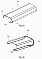
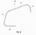
- the edge protection element 64 ( Figs. 4a to 4c ) is formed in one piece in the exemplary embodiment shown, which is in particular a component made of sheet metal.
- a top side 72 of the edge protection element 64 can have a texture to improve slip resistance. This makes it possible for children, for example, to climb onto the top 72 and not slip off. It is also possible to use a container or the like when loading the cargo bike container 50. on the top 72 first before it is completely lifted into the cargo bike container 50.
- the edge protection element also has two mutually opposite side parts 74, which rest against an inside or an outside of the corresponding wall 54, 56, 58 when the edge protection element 64 is plugged onto the upper edge 62 from above, ie mounted. Furthermore, the edge protection element 64 has an approach 80. In the assembled state, the extension 80 points in the direction of the corresponding wall 54, 56, 58, onto the upper edge 62 of which the edge protection element 64 has been attached. The approach 80 engages behind a bead or protrudes into a groove. In the exemplary embodiment shown, the groove is formed by the circumferential recess 70 in which the bracket elements 78 are arranged. Accordingly, a bead is arranged above this groove or depression 70. The extension 80 of the edge protection element thus engages into this groove from the outside and is arranged above the bracket elements 78 in the assembled state.
- edge protection element 64 Due to the design of the edge protection element 64, in particular by the provision of the extension 80 on the edge protection element 64, in the insertion direction (in the Figs. 2 and 3 from above) an undercut is formed.
- the approach 80 can also be omitted. This is possible in particular if the edge protection element 64 is fixed by gluing or at least additionally by gluing. If the extension 80 is not provided, the edge protection element can either end straight, so that the side part 74 ends straight or flat. Also can on in Fig. 4c At the bottom end of the side part 74, an arcuate, inward-pointing extension can be provided, which causes a clamping grip from behind. In this respect, gluing may not necessarily be necessary.
- the surface protection element 68 ( Figs. 5a to 5c ) can have a texture on a top side 82.
- the top 82 is the surface on which the foot is placed.
- the surface protection element 68 has a lower part 86 opposite the upper part 84, which in the assembled state is arranged on the underside opposite the upper part 88.
- the surface protection element 68 which is in particular designed in one piece, has a front part 92 which covers a front edge 94.
- the surface protection element 68 is plugged from the outside onto the lower region of the tread opening 66 that forms the tread surface.
- the surface protection element 68 does not have a shoulder that engages in a groove and forms an undercut in the assembly direction, the surface protection element 68 is fixed by gluing.
- the surfaces against which the inside of the surface protection element 68 rests are treated accordingly in order to ensure a secure adhesive connection. This can be done by roughening or the like. take place. It is preferred that these surfaces are fluorinated.
- this can also be additionally glued, in which case it is again preferred that the corresponding surfaces are treated to improve the adhesive connection.
Landscapes
- Engineering & Computer Science (AREA)
- Mechanical Engineering (AREA)
- Packaging Of Machine Parts And Wound Products (AREA)
- Details Of Rigid Or Semi-Rigid Containers (AREA)
Description
- Die Erfindung betrifft einen Lastenfahrradbehälter.
- Lastenfahrräder, die zum Transport von Personen, insbesondere Kindern oder Lasten, geeignet sind, weisen einen Lastenfahrradbehälter auf. Lastenfahrradbehälter sind aus unterschiedlichem Material hergestellt. Insbesondere bei Lastenfahrradbehältern, die aus Kunststoffmaterial hergestellt sind, sind insbesondere Kanten erheblichem Verschleiß oder Beschädigungen ausgesetzt. Insbesondere die Oberkanten des Lastenfahrradbehälters sind stark beansprucht. Die Beanspruchung erfolgt beispielsweise beim Ein- und Aussteigen von Kindern sowie auch beim Einladen insbesondere schwerer Lasten, da diese häufig auf der Oberkante des Lastenfahrradbehälters abgestellt werden, bevor ein vollständiges Einladen erfolgt. Kinder treten beim Einsteigen und Aussteigen häufig auf die Oberkante des Lastenfahrradbehälters.
- Ein Lastenfahrradbehälter mit den Merkmalen des Oberbegriffs des Anspruchs 1 ist in dem "Butchers & Bicycles Mk1-E" beschrieben. Auch die gattungsgemäße URL:https://web.archive.org/web/20151213000300/http:// www.urbanarrow.com/en/cargo-bike offenbart die Merkmale des Oberbegriffes des Anspruchs 1.
- Aufgabe der Erfindung ist es, einen Lastenfahrradbehälter zu schaffen, bei dem das Einsteigen in einen Lastenfahrradbehälter vereinfacht ist.
- Die Lösung der Aufgaben erfolgt durch einen Lastenfahrradbehälter gemäß Anspruch 1.
- Ein erfindungsgemäßer Lastenfahrradbehälter weist ein Bodenelement, zwei einander gegenüberliegende Seitenwände, eine Rückwand sowie eine
- Vorderwand auf. Hierbei kann der Lastenfahrradbehälter aus mehreren Einzelteilen zusammengesetzt sein. Insbesondere sind einzelne Elemente einstückig ausgebildet, wobei beispielsweise eine Seitenwand einstückig zumindest mit einem Teil der Vorwand oder einem Teil der Rückwand und/oder des Bodenelements ausgebildet ist. Besonders bevorzugt ist es, dass der Lastenfahrradbehälter im Wesentlichen aus zwei Teilen aufgebaut ist, die vertikal geteilt sind, so dass in besonders bevorzugter Ausführungsform jedes Bauteil eine Seitenwand und einen Teil der Vorderwand, der Rückwand und des Bodenelements aufweist. Vorzugsweise ist der Lastenfahrradbehälter somit in einer vertikalen Ebene geteilt.
- Der erfindungsgemäße Lastenfahrradbehälter mit verbessertem Einstieg, ist insbesondere für Kinder geeignet. Erfindungsgemäß ist in mindestens einer der Seitenwände und/oder der Rückwand und/oder der Vorderwand eine Trittöffnung vorgesehen. Es ist somit insbesondere für Kinder möglich, zunächst einen Fuß in die Trittöffnung zu setzen und sodann das andere Bein über die Seitenwand, die Rückwand oder die Vorderwand zu bewegen, um in den Lastenfahrradbehälter einzusteigen. Zum Aussteigen kann die Trittöffnung ebenfalls genutzt werden. Bei einem auf dem Lastenfahrrad montierten Lastenfahrradbehälter befindet sich die Trittöffnung vorzugsweise 15 bis 35 cm über dem Boden.
- Die Trittöffnung ist erfindungsgemäß seitlich in der Seitenwand und/oder der Rückwand und/oder der Vorderwand angeordnet. Die Trittfläche der Trittöffnung ist hierbei durch die entsprechende Wand ausgebildet. Hierbei ist es nicht erforderlich, dass unmittelbar unter der Trittöffnung ein Versteifungselement bzw. ein Rahmenelement vorgesehen ist.
- Unabhängig vom Aufbau des Lastenfahrradbehälters ist vorzugsweise zum Verringern der Gefahr des Beschädigens an einer Oberkante ein Kantenschutzelement vorgesehen. Bei der Oberkante handelt es sich um eine Oberkante zumindest einer der Seitenwände und/oder der Rückwand und/oder der Vorderwand. Durch das Kantenschutzelement ist die Oberkante zumindest teilweise geschützt. Vorzugsweise ist ein Schutzelement in demjenigen Bereich, in dem beispielsweise Kinder auf die Oberkante treten oder in demjenigen Bereich, in dem Lasten in den Lastenfahrradbehälter geladen werden, angeordnet. Insofern ist es besonders bevorzugt, dass an den Oberkanten der beiden einander gegenüberliegenden Seitenwände jeweils ein Kantenschutzelement vorgesehen ist. Es ist auch möglich, ein umlaufendes Kantenschutzelement vorzusehen, so dass die gesamten Oberkanten geschützt sind. Ein derartiges Kantenschutzelement ist ggf. ein- oder mehrteilig ausgebildet.
- Vorzugsweise ist das Kantenschutzelement formschlüssig mit der Oberkante verbunden. Durch eine derartige formschlüssige Verbindung erfolgt eine sichere und zuverlässige Verbindung des Kantenschutzelements mit der Oberkante des Lastenfahrradbehälters. Zusätzlich oder anstelle einer formschlüssigen Verbindung kann eine kraftschlüssige Verbindung mit der Oberkante, insbesondere durch Verkleben, erfolgen.
- In besonders bevorzugter Weiterbildung der Erfindung umgreift das Kantenschutzelement die Oberkante zumindest teilweise. Insbesondere umgreift das Kantenschutzelement die Oberkante an einer Innenseite und/oder einer Außenseite der zumindest einen Seitenwand und/oder der Rückwand und/oder der Vorderwand. Bevorzugt ist es, dass das Kantenschutzelement die Oberkante an der Innenseite und der Außenseite umgreift. Ein derartiges Kantenschutzelement ist im Querschnitt zumindest teilweise U-förmig ausgebildet, wobei zusätzliche Ansätze wie nachstehend beschrieben vorgesehen sein können. Durch eine derartige Ausgestaltung des Kantenschutzelements sind die Oberkanten nicht nur auf einer Oberseite, sondern auch an einer Innenseite und Außenseite im Bereich der Oberkante geschützt. Hierdurch ist einerseits der Schutz verbessert und andererseits die Befestigung des Kantenschutzelements an der Oberkante verbessert.
- Vorzugsweise ist an der Oberkante, insbesondere im Bereich der Oberkante, ein Wulst vorgesehen. Ein entsprechender Wulst ist an der Innenseite und/oder der Außenseite im Bereich zumindest einer der Seitenwände und/oder der Rückwand und/oder der Vorderwand vorgesehen. In dieser bevorzugten Ausführungsform ist der mindestens eine Wulst durch mindestens einen Ansatz des Kantenschutzelementes umgriffen. Durch ein derartiges Umgreifen ist die Verbindung des Kantenschutzelements mit der Oberkante weiter verbessert. In vertikaler Richtung, d.h. nach oben, hintergreift der mindestens eine Ansatz des Kantenschutzelements somit den Wulst. Vorzugsweise ist durch den Wulst somit ein Hinterschnitt ausgebildet. Beim Montieren oder auch beim Demontieren des Kantenschutzelements ist es somit erforderlich, das Kantenschutzelement ggf. etwas aufzubiegen oder elastisch zu verformen. Insbesondere schnappt das Kantenschutzelement bei der Demontage auf Grund des Hinterschnitts ein bzw. rastet in dieser Position ein.
- Besonders bevorzugt ist es, dass die Oberkante in dem Bereich, in dem ein Kantenschutzelement angeordnet wird, nicht durch Befestigungselemente, wie Schrauben, Stifte u.dgl., beschädigt wird. Hierdurch würde ggf. die Stabilität des insbesondere aus einem Kunststoffmaterial hergestellten Lastenfahrradbehälters beeinträchtigt.
- Alternativ oder zusätzlich zu einem Wulst kann insbesondere an einer Außenseite und/oder einer Innenseite einer der Seitenwände und/oder der Rückwand und/oder der Vorderwand im Bereich der Oberkante eine Nut vorgesehen sein. In die Nut ragt in montiertem Zustand ein Ansatz des Kantenschutzelements. Hierdurch ist wiederum ein Hinterschnitt verwirklicht, so dass insbesondere eine gute formschlüssige Verbindung des Kantenschutzelements mit der Oberkante realisiert ist.
- Der mindestens eine Ansatz des Kantenschutzelements, der den Wulst umgreift und/oder in die Nut ragt, weist in montiertem Zustand nach innen in Richtung der entsprechenden Seitenwand und/oder Rückwand und/oder Vorderwand.
- Vorzugsweise umgreift das Kantenschutzelement die Oberkante um mehr als 180°. Auch hierdurch ist wiederum ein entsprechender Hinterschnitt und ein zuverlässiges Verbinden des Kantenschutzelements mit der Oberkante realisiert. Hierbei kann das Kantenschutzelement mehrere insbesondere ebene und/oder gekrümmte Bereiche aufweisen. Im Querschnitt kann das Kantenschutzelement somit mehreckig und/oder zumindest teilweise konvex gekrümmt ausgebildet sein.
- Des Weiteren ist es möglich, zusätzlich oder anstelle der formschlüssigen Verbindung eines Kantenschutzelements mit der Oberkante eine kraftschlüssige Verbindung, insbesondere durch Verkleben, herzustellen. Bevorzugt ist es, dass sowohl eine kraftschlüssige als auch eine formschlüssige Verbindung erfolgt. Die insbesondere durch Verkleben hergestellte kraftschlüssige Verbindung kann dadurch verbessert werden, dass die Oberkante im Bereich des Kantenschutzelements zumindest teilweise behandelt ist. Eine entsprechende Oberflächenbehandlung kann durch Aufrauen der Oberfläche erfolgen. Besonders bevorzugt ist es, dass die Oberfläche in diesem Bereich zumindest teilweise durch Halogenieren, insbesondere Fluorieren, behandelt ist. Insbesondere durch Fluorieren erfolgt ein Verändern der Oberfläche des insbesondere in diesem Bereich aus Kunststoff hergestellten Lastenfahrradbehälters derart, dass eine sehr feste Klebeverbindung realisiert werden kann. Dies ist insbesondere der Fall, wenn der Lastenfahrradbehälter zumindest in dem Bereich, in dem die Kantenschutzelemente angeordnet sind, aus einem Kunststoffmaterial hergestellt ist. Insbesondere ist ein derartiges Behandeln der Oberfläche vorteilhaft, wenn zumindest dieser Bereich des Lastenfahrradbehälters einen Partikelschaum, insbesondere EPP (expandierbares Polypropylen) aufweist bzw. aus diesem Material hergestellt ist.
- Insbesondere auf Grund des beschriebenen bevorzugten verwendeten Materials für den Lastenfahrradbehälter ist diese Ausgestaltung möglich. Als Material wird insbesondere die Verwendung eines Partikelschaums und besonders bevorzugt die Verwendung von EPP bevorzugt. Es ist insofern erfindungsgemäß möglich und besonders bevorzugt, dass die Trittöffnung ausschließlich von Material des Lastenfahrradbehälters umgeben ist. Insbesondere ist die Trittöffnung unabhängig von dem Rahmenelement angeordnet. Beispielsweise kann der relevante Teil des Fahrradrahmens unterhalb dem Bodenelement des Lastenfahrradbehälters angeordnet sein, so dass die Trittöffnung seitlich neben und nicht oberhalb von Rahmenelementen angeordnet ist. Die beim Betreten der Trittöffnung auftretenden senkrechten Kräfte wirken somit im Wesentlichen, insbesondere ausschließlich, auf den Lastenfahrradbehälter. Selbstverständlich werden diese Kräfte seitlich in Richtung des Rahmens umgelenkt. Auf Grund der hohen Eigenstabilität des verwendeten Materials ist ein unmittelbares Abfangen der Kräfte durch ein unterhalb der Trittöffnung vorgesehenes Versteifungselement, insbesondere ein Rahmenelement, nicht erforderlich.
- In besonders bevorzugter Ausführungsform ist zumindest an einer Oberseite der Trittöffnung, d.h. insbesondere der Trittfläche, ein Oberflächenschutzelement vorgesehen.
- Vorzugsweise ist das Oberflächenschutzelement nicht nur an der Oberseite der Trittöffnung, sondern zusätzlich auch an einer der Oberseite gegenüberliegenden Unterseite und/oder einer Vorderkante vorgesehen. Die Vorderkante ist hierbei die nach außen weisende Kante unterhalb der Trittfläche. In besonders bevorzugter Ausführungsform ist das Oberflächenschutzelement somit im Querschnitt im Wesentlichen U-förmig ausgebildet.
- Das Befestigen des Oberflächenschutzelements erfolgt in bevorzugter Ausführungsform kraftschlüssig, insbesondere durch Verkleben. Hierbei ist es entsprechend der Befestigung des Kantenschutzelements bevorzugt, dass die entsprechende Oberfläche zumindest teilweise behandelt ist, wobei wiederum ein Halogenieren, insbesondere Fluorieren der Oberfläche bevorzugt ist. Ggf. kann auch eine formschlüssige Verbindung erfolgen, indem zusätzlich eine Wulst oder eine Nut vorgesehen ist, in die ein Ansatz des Oberflächenschutzelements eingreift bzw. einrastet.
- Vorzugsweise ist das Kantenschutzelement oder das Oberflächenschutzelement aus verschleißfestem Material hergestellt bzw. weist verschleißfestes Material auf. Insbesondere ist es bevorzugt, dass das Kantenschutzelement und/oder das Oberflächenschutzelement ein Metall aufweist, insbesondere aus Metall hergestellt ist. Besonders bevorzugt ist es, das Kantenschutzelement und/oder das Oberflächenschutzelement aus Blech herzustellen.
- Der Lastenfahrradbehälter ist vorzugsweis derart ausgebildet, dass zumindest die Seitenwände und/oder die Rückwand und/oder die Vorderwand und/oder das Bodenelement zumindest teilweise, insbesondere vollständig, aus Kunststoff hergestellt ist. Ferner ist es bevorzugt, dass es sich bei dem Kunststoff um einen Partikelschaum handelt. Besonders bevorzugt ist die Verwendung von EPP (expandierbares Polypropylen). Hierbei ist es bevorzugt, dass der Lastenfahrradbehälter das vorstehende Material aufweist und insbesondere aus diesem hergestellt ist.
- Nachfolgend wird die Erfindung anhand einer bevorzugten Ausführungsform unter Bezugnahme auf die anliegenden Zeichnungen näher erläutert.
- Es zeigen:
-
Fig. 1 eine schematische Seitenansicht eines Lastenfahrrads mit dem erfindungsgemäß ausgebildeten Lastenaufnahmebehälter, -
Fig. 2 eine perspektivische Seitenansicht eines erfindungsgemäßen Lastenaufnahmebehälters, -
Fig. 3 einen schematischen perspektivischen Querschnitt des inFig. 2 dargestellten Lastenaufnahmebehälters, -
Fig. 4a eine schematische perspektivische Draufsicht eines Kantenschutzelements, -
Fig. 4b eine schematische perspektivische Unteransicht des Kantenschutzelements, -
Fig. 4c eine schematische Schnittansicht des Kantenschutzelements, -
Fig. 5a eine schematische Draufsicht des Oberflächenschutzselements, -
Fig. 5b eine schematische perspektivische Innenansicht des Oberflächenschutzelements und -
Fig. 5c eine schematische Schnittansicht des Oberflächenschutzelements. - Eine bevorzugte Ausführungsform des erfindungsgemäßen Lastenfahrrads wie in
Figur 1 dargestellt weist einen Lastenfahrrad-Rahmen 10 auf. Der Lastenfahrrad-Rahmen 10 weist im dargestellten Ausführungsbeispiel ein Sattelrohr 14, ein Oberrohr 15 und ein von einer Abdeckung verdecktes Unterrohr 16 sowie ein Lenkerrohr 18 auf. In dem Lenkerrohr 18 ist ein schwenkbares Rohr angeordnet, das mit einem Lenker 20 verbunden ist. Ferner ist zwischen dem Unterrohr 16 und dem Sattelrohr 14 im dargestellten Ausführungsbeispiel eine Antriebseinrichtung 22 angeordnet. Diese weist ein herkömmliches Tretlager auf, das mit einem Elektromotor verbunden ist, so dass das Treten von einem Elektromotor unterstützt werden kann. Der Antrieb eines Hinterrades 24 erfolgt über einen Antrieb mittels Zahnriemen 25 oder dergleichen. Ferner weist der Lastenfahrrad-Rahmen 10 einen Hinterbau 26 auf, der das Hinterrad 24 trägt. In dem dargestellten Ausführungsbeispiel ist ein einspuriges Lastenfahrrad dargestellt. - Mit dem Lenkerrohr 18 ist ein Griffelement 46 verbunden. Im dargestellten Ausführungsbeispiel ist das Griffelement an einer Rückseite des Lenkerrohrs 18 angeordnet und weist in Richtung des Hinterbaus 26 bzw. in Richtung des Sattelrohrs 14. Das Griffelement 46 ist somit in der Rahmenmittelebene angeordnet, in der beim dargestellten Lastenfahrrad auch die beiden Räder sowie das Sattelrohr 14, das Unterrohr 16 und das Lenkerrohr 18 angeordnet sind.
- Um das Lastenrad anzuheben oder beispielsweise auf einen Hauptständer 60 zu heben, kann der Nutzer insbesondere am oberen Teil 48 des Griffelements angreifen.
- Ein Lastenfahrradbehälter 50 weist ein Bodenelement 52, zwei Seitenelemente 54, eine Rückwand 56 sowie eine Vorderwand 58 auf. In dem dargestellten besonders bevorzugten Ausführungsbeispiel ist der Lastenfahrradbehälter aus im Wesentlichen zwei Kunststoffteilen ausgebildet. Die beiden Kunststoffteile sind zu einer vertikalen Mittelebene, die in montiertem Zustand der Fahrradmittelebene entspricht, spiegelbildlich ausgebildet. Jede der beiden Kunststoffteil-Hälften weist somit eine Seitenwand 54, eine halbe Rückwand 56, eine halbe Vorderwand 58 und eine halbes Bodenelement 52 auf.
- Im vorderen oberen Endbereich der Vorderwand 58 ist ferner ein Ansatz 76 vorgesehen. Dieser verdeckt eine Oberseite des Gabelschafts. Der Ansatz 76 ragt in Fahrtrichtung über den oberen Bereich des Gabelelements und dient u.A. als Aufprallschutz.
- Die beiden Hälften aus Kunststoff werden zu dem in
Fig. 2 dargestellten Lastenfahrradbehälter zusammengesetzt. Zur Fixierung bzw. Verbindung der beiden Hälften ist in einem oberen Bereich ein aus zwei Bügelelementen 78 bestehender Verbindungsbügel vorgesehen. Die beiden Bügelelemente werden im Bereich der Trennebene mit entsprechenden Verbindungselementen verbunden. Die Trennebene ist die inFig. 3 dargestellte Vorderseite der Hälfte der Rückwand 56 bzw. der Hälfte der Vorderwand 58 sowie der Hälfte des Bodenelements 52. Die beiden Bügelelemente 78 werden fest miteinander verbunden bzw. verspannt, so dass diese eine Klammer im oberen Bereich des Lastenfahrradbehälters ausbilden. - Die beiden Seitenwände 54, die Rückwand 56 sowie die Vorderwand 58 weisen jeweils eine Oberkante 62 auf. An der Oberkante 62 kann nur in Teilbereichen oder umlaufend ein Kantenschutzelement 64 vorgesehen sein. Besonders bevorzugt ist es hierbei, dass das Kantenschutzelement 64 an den Oberkanten 62 der Seitenwände 54 insbesondere im Mittelbereich vorgesehen ist. Hierdurch ist es vermieden, dass insbesondere Kinder beim Ein- oder Aussteigen aus dem Lastenfahrradbehälter 50 die Oberkante 62 der Seitenwände 54 beschädigen. Zum Ein- und Aussteigen weist zumindest eine der beiden Seitenwände 54 vorzugsweise eine Trittöffnung 66 auf. Zum Schutz der Oberfläche der Trittöffnung 66 ist ein Oberflächenschutzelement 68 vorgesehen.
- Das Kantenschutzelement 64 (
Fign. 4a bis 4c ) ist im dargestellten Ausführungsbeispiel einteilig ausgebildet, wobei es sich insbesondere um ein aus Blech hergestelltes Bauteil handelt. Eine Oberseite 72 des Kantenschutzelements 64 kann hierbei eine Textur zur Verbesserung der Rutschsicherheit aufweisen. Hierdurch ist es möglich, dass Kinder beispielsweise auf die Oberseite 72 steigen können und hierbei nicht abrutschen. Auch beim Beladen des Lastenfahrradbehälters 50 ist es möglich, einen Behälter o.dgl. auf der Oberseite 72 zunächst abzustellen, bevor dieser vollständig in den Lastenfahrradbehälter 50 gehoben wird. - Das Kantenschutzelement weist ferner zwei einander gegenüberliegende Seitenteile 74 auf, die bei von oben auf die Oberkante 62 aufgesteckten, d.h. montierten Kantenschutzelement 64, an einer Innenseite bzw. einer Außenseite der entsprechenden Wand 54,56,58 anliegen. Des Weiteren weist das Kantenschutzelement 64 einen Ansatz 80 auf. In montiertem Zustand weist der Ansatz 80 in Richtung der entsprechenden Wand 54,56,58, auf dessen Oberkante 62 das Kantenschutzelement 64 aufgesteckt wurde. Der Ansatz 80 hintergreift eine Wulst oder ragt in eine Nut. Im dargestellten Ausführungsbeispiel ist die Nut durch die umlaufende Vertiefung 70 ausgebildet, in der die Bügelelemente 78 angeordnet sind. Entsprechend ist oberhalb dieser Nut oder Vertiefung 70 eine Wulst angeordnet. Der Ansatz 80 des Kantenschutzelements greift somit von außen in diese Nut und ist in montiertem Zustand oberhalb der Bügelelemente 78 angeordnet.
- Durch die Ausgestaltung des Kantenschutzelements 64, insbesondere durch das Vorsehen des Ansatzes 80 an dem Kantenschutzelement 64, ist in Einsetzrichtung (in den
Fign. 2 und3 von oben) ein Hinterschnitt ausgebildet. - Je nach Ausführungsform des Kantenschutzelements kann der Ansatz 80 auch entfallen. Dies ist insbesondere dann möglich, wenn das Kantenschutzelement 64 durch Verkleben oder zumindest zusätzlich durch Verkleben fixiert wird. Wenn der Ansatz 80 nicht vorgesehen ist, kann das Kantenschutzelement entweder gerade enden, so dass das Seitenteil 74 gerade bzw. flach endet. Auch kann am in
Fig. 4c unteren Ende des Seitenteils 74 noch ein bogenförmiger, nach innen weisender Ansatz vorgesehen sein, der ein klemmendes Hintergreifen bewirkt. Insofern ist sodann ggf. nicht unbedingt ein Verkleben erforderlich. - Das Oberflächenschutzelement 68 (
Fign. 5a bis 5c ) kann an einer Oberseite 82 eine Textur aufweisen. Bei der Oberseite 82 handelt es sich um die Fläche, auf die der Fuß aufgesetzt wird. Ferner weist das Oberflächenschutzelement 68 ein dem Oberteil 84 gegenüberliegendes Unterteil 86 auf, das in montiertem Zustand an der der Oberseite 88 gegenüberliegenden Unterseite angeordnet ist. Ferner weist das insbesondere einstückig ausgebildete Oberflächenschutzelement 68 ein Vorderteil 92 auf, das eine Vorderkante 94 bedeckt. Zur Montage wird das Oberflächenschutzelement 68 von außen auf den die Trittfläche ausbildenden unteren Bereich der Trittöffnung 66 aufgesteckt. - Da im dargestellten Ausführungsbeispiel das Oberflächenschutzelement 68 keinen Ansatz aufweist, der in eine Nut eingreift und in Montagerichtung einen Hinterschnitt ausbildet, wird das Oberflächenschutzelement 68 durch Verkleben fixiert. Hierzu ist es besonders bevorzugt, dass die Flächen, an denen die Innenseite des Oberflächenschutzelements 68 anliegt, entsprechend behandelt werden, um eine sichere Klebeverbindung zu gewährleisten. Dies kann durch Aufrauen o.dgl. erfolgen. Bevorzugt ist es, dass ein Fluorieren dieser Oberflächen erfolgt.
- Zur Verbesserung der Fixierung des Kantenschutzelements 64 kann dies ebenfalls zusätzlich verklebt werden, wobei es auch hierbei wieder bevorzugt ist, dass die entsprechenden Oberflächen zur Verbesserung der Klebeverbindung behandelt sind.
Claims (22)
- Lastenfahrradbehälter miteinem Bodenelement (52), zwei einander gegenüberliegenden Seitenwänden (54), einer Rückwand (56),einer Vorderwand (58), undeiner mindestens an einer der Seitenwände (54) und/oder der Rückwand (56) und/oder der Vorderwand (58) vorgesehenen Trittöffnung (66)dadurch gekennzeichnet, dassdie Trittöffnung (66) vollständig von der Seitenwand (54) und/oder der Rückwand (56) und/oder der Vorderwand (58) umgeben ist, wobei die Trittöffnung (66) insbesondere vollständig von dem Material der Seitenwand (54) und/oder der Rückwand (56) und/oder der Vorderwand (58) umgeben ist.
- Lastenfahrradbehälter nach Anspruch 1, gekennzeichnet durch ein zumindest an einer Oberseite (88) der Trittöffnung (66) vorgesehenes Oberflächenschutzelement (68).
- Lastenfahrradbehälter nach Anspruch 1 oder 2, dadurch gekennzeichnet, dass das Oberflächenschutzelement (68) zusätzlich an einer der Oberseite (88) gegenüberliegenden Unterseite und/oder Vorderkante (94) vorgesehen ist.
- Lastenfahrradbehälter nach Anspruch 1 bis 3, dadurch gekennzeichnet, dass das Oberflächenschutzelement (68) einen im Wesentlichen U-förmigen Querschnitt aufweist.
- Lastenfahrradbehälter nach einem der Ansprüche 1 bis 4, dadurch gekennzeichnet, dass das Oberflächenschutzelement kraftschlüssig, insbesondere durch Verkleben, verbunden ist.
- Lastenfahrradbehälter nach Anspruch 5, dadurch gekennzeichnet, dass die Oberseiten der Trittöffnung (66), an denen des Oberflächenschutzelements angeordnet ist, zumindest teilweise zur kraftschlüssigen Verbindung behandelt sind.
- Lastenfahrradbehälter nach Anspruch 6, dadurch gekennzeichnet, dass die Behandlung durch Halogenieren, insbesondere Fluorieren, erfolgt.
- Lastenfahrradbehälter nach einem der Ansprüche 1 bis 7, gekennzeichnet durch ein an einer Oberkante (62) zumindest einer der Seitenwände (54) und/oder der Rückwand (56) und/oder der Vorderwand (58) vorgesehenes Kantenschutzelement (64).
- Lastenfahrradbehälter nach Anspruch 8, dadurch gekennzeichnet, dass das Kantenschutzelement (64) formschlüssig mit der Oberkante (62) verbunden ist.
- Lastenfahrradbehälter nach Anspruch 8 oder 9, dadurch gekennzeichnet, dass das Kantenschutzelement (64) die Oberkante (62) eine Innenseite und/oder eine Außenseite zumindest einer der Seitenwände (54) und/oder der Rückwand (56) und/oder der Vorderwand (58) umgreift.
- Lastenfahrradbehälter nach einem der Ansprüche 8 bis 10, dadurch gekennzeichnet, dass im Bereich der Oberkante (62), insbesondere einer Außenseite und/oder einer Innenseite der zumindest einen Seitenwand (54) und/oder Rückwand (56) und/oder Vorderwand (58), im Bereich der Oberkante (62) eine Wulst vorgesehen ist, die ein Ansatz (86) des Kantenschutzelements umgreift.
- Lastenfahrradbehälter nach Anspruch 11, dadurch gekennzeichnet, dass die Wulst einen Hinterschnitt ausbildet.
- Lastenfahrradbehälter nach einem der Ansprüche 8 bis 12, dadurch gekennzeichnet, dass an der Oberkante (62) insbesondere an einer Außenseite und/oder einer Innenseite der zumindest einen Seitenwand (54) und/oder der Rückwand (56) und/oder der Vorderwand (58) im Bereich der Oberkante (62) eine Nut (70) vorgesehen ist, in die ein Ansatz (86) des Kantenschutzelements (68) ragt.
- Lastenfahrradbehälter nach einem der Ansprüche 11 bis 13, dadurch gekennzeichnet, dass der Ansatz (86) des Kantenschutzelements (68) in moniertem Zustand nach innen in Richtung der zumindest einen Seitenwand (54) und/oder der Rückwand (56) und/oder der Vorderwand (58) ragt.
- Lastenfahrradbehälter nach einem der Ansprüche 8 bis 14, dadurch gekennzeichnet, dass das Kantenschutzelement (68) die Oberkante (62) um mehr als 180° umgreift.
- Lastenfahrradbehälter nach einem der Ansprüche 8 bis 15, dadurch gekennzeichnet, dass das Kantenschutzelement (68) umlaufend an allen Oberkanten (62) der Seitenwände (54), der Rückwand (56) und der Vorderwand (58) vorgesehen ist.
- Lastenfahrradbehälter nach einem der Ansprüche 8 bis 16, dadurch gekennzeichnet, dass das Kantenschutzelement (68) kraftschlüssig mit der Oberkante (62) verbunden, insbesondere verklebt ist.
- Lastenfahrradbehälter nach Anspruch 17, dadurch gekennzeichnet, dass die Oberkante (62) im Bereich des Kantenschutzelements (68) zumindest teilweise zur kraftschlüssigen Verbindung behandelt ist.
- Lastenfahrradbehälter nach Anspruch 18, dadurch gekennzeichnet, dass die Behandlung durch Halogenieren, insbesondere Fluorieren, erfolgt.
- Lastenfahrradbehälter nach einem der Ansprüche 1 bis 19, dadurch gekennzeichnet, dass das Kantenschutzelement (64) und/oder das Oberflächenschutzelement (68) ein verschleißfestes Material aufweist, insbesondere aus verschleißfestem Material hergestellt ist, wobei das Kantenschutzelement (64) und/oder das Oberflächenschutzelement (68) insbesondere als Metallblech ausgebildet ist.
- Lastenfahrradbehälter nach einem der Ansprüche 1 bis 20, dadurch gekennzeichnet, dass die beide Seitenwände (54) und/oder die Rückwand (56) und/oder die Vorderwand (58) und/oder das Bodenelement (52) zumindest teilweise, insbesondere vollständig, aus Kunststoff hergestellt ist.
- Lastenfahrradbehälter nach Anspruch 21, dadurch gekennzeichnet, dass der Kunststoff ein Partikelschaum, insbesondere EPP (expandierbares Polypropylen) aufweist, insbesondere aus diesem Material hergestellt ist.
Applications Claiming Priority (1)
| Application Number | Priority Date | Filing Date | Title |
|---|---|---|---|
| DE202020101380.7U DE202020101380U1 (de) | 2020-03-12 | 2020-03-12 | Lastenfahrradbehälter |
Publications (2)
| Publication Number | Publication Date |
|---|---|
| EP3878727A1 EP3878727A1 (de) | 2021-09-15 |
| EP3878727B1 true EP3878727B1 (de) | 2023-09-27 |
Family
ID=74873491
Family Applications (1)
| Application Number | Title | Priority Date | Filing Date |
|---|---|---|---|
| EP21161935.8A Active EP3878727B1 (de) | 2020-03-12 | 2021-03-11 | Lastenfahrradbehälter |
Country Status (2)
| Country | Link |
|---|---|
| EP (1) | EP3878727B1 (de) |
| DE (1) | DE202020101380U1 (de) |
Families Citing this family (1)
| Publication number | Priority date | Publication date | Assignee | Title |
|---|---|---|---|---|
| US12084264B2 (en) | 2022-10-28 | 2024-09-10 | Specialized Bicycle Components, Inc. | Packaging system for a bicycle |
Family Cites Families (3)
| Publication number | Priority date | Publication date | Assignee | Title |
|---|---|---|---|---|
| NL2006612C2 (en) | 2011-04-15 | 2012-10-16 | Noorenz B V | Vehicle frame and vehicle comprising such frame. |
| SE538830C2 (en) * | 2014-10-13 | 2016-12-20 | Livelo Ab | A transport container with a chair |
| US9840301B2 (en) * | 2015-07-21 | 2017-12-12 | Taga Bikes Ltd | Cargo cycle with passenger seats |
-
2020
- 2020-03-12 DE DE202020101380.7U patent/DE202020101380U1/de active Active
-
2021
- 2021-03-11 EP EP21161935.8A patent/EP3878727B1/de active Active
Also Published As
| Publication number | Publication date |
|---|---|
| EP3878727A1 (de) | 2021-09-15 |
| DE202020101380U1 (de) | 2021-06-15 |
Similar Documents
| Publication | Publication Date | Title |
|---|---|---|
| DE3718966C2 (de) | ||
| DE3416222C2 (de) | Treppensteigende Rollstuhl-Transporteinrichtung | |
| EP0542000B1 (de) | Plattformwagen mit Schiebegriff | |
| DE2926596A1 (de) | Transportkarre | |
| DE20206816U1 (de) | Roller | |
| EP4026761A1 (de) | Lastenfahrradbehälter | |
| EP3878727A1 (de) | Lastenfahrradbehälter | |
| EP3904236A1 (de) | Fahrrad-transportverpackung | |
| EP3996982A1 (de) | Lastenfahrradrahmen | |
| EP3849890B1 (de) | Lastenfahrradbehälter | |
| DE19711042A1 (de) | Kombinierter Personen- und Transportroller | |
| DE20116389U1 (de) | Versandgestell für Motorräder | |
| EP0926055A2 (de) | Klappbares-Transportfahrzeug | |
| DE4330019A1 (de) | Hebe- und Transportvorrichtung für ein schmales Transportgut auf einem Fahrzeugdach | |
| EP3909837B1 (de) | Lastenfahrradbehälter | |
| EP2810849B1 (de) | Transportwagen | |
| EP0056490A2 (de) | Handkarre | |
| DE102021204801A1 (de) | Fahrradanhängeranordnung | |
| DE3613136C2 (de) | Laufrolle für Transportwagen | |
| DE20012130U1 (de) | Tragkonstruktion für Behälter | |
| DE202004014273U1 (de) | Multifunktions-Fahrradanhänger | |
| DE102016208997B4 (de) | Transportvorrichtung für ein Kind mit einer Handschutzvorrichtung | |
| EP4188783B1 (de) | Haube für einen lastenfahrradbehälter | |
| EP3960600B1 (de) | Transportvorrichtung | |
| DE8120301U1 (de) | "hubroller" |
Legal Events
| Date | Code | Title | Description |
|---|---|---|---|
| PUAI | Public reference made under article 153(3) epc to a published international application that has entered the european phase |
Free format text: ORIGINAL CODE: 0009012 |
|
| STAA | Information on the status of an ep patent application or granted ep patent |
Free format text: STATUS: THE APPLICATION HAS BEEN PUBLISHED |
|
| AK | Designated contracting states |
Kind code of ref document: A1 Designated state(s): AL AT BE BG CH CY CZ DE DK EE ES FI FR GB GR HR HU IE IS IT LI LT LU LV MC MK MT NL NO PL PT RO RS SE SI SK SM TR |
|
| STAA | Information on the status of an ep patent application or granted ep patent |
Free format text: STATUS: REQUEST FOR EXAMINATION WAS MADE |
|
| 17P | Request for examination filed |
Effective date: 20220304 |
|
| RBV | Designated contracting states (corrected) |
Designated state(s): AL AT BE BG CH CY CZ DE DK EE ES FI FR GB GR HR HU IE IS IT LI LT LU LV MC MK MT NL NO PL PT RO RS SE SI SK SM TR |
|
| GRAP | Despatch of communication of intention to grant a patent |
Free format text: ORIGINAL CODE: EPIDOSNIGR1 |
|
| STAA | Information on the status of an ep patent application or granted ep patent |
Free format text: STATUS: GRANT OF PATENT IS INTENDED |
|
| RIC1 | Information provided on ipc code assigned before grant |
Ipc: B62J 9/20 20200101ALI20230222BHEP Ipc: B62K 7/04 20060101ALI20230222BHEP Ipc: B62K 19/46 20060101AFI20230222BHEP |
|
| INTG | Intention to grant announced |
Effective date: 20230322 |
|
| P01 | Opt-out of the competence of the unified patent court (upc) registered |
Effective date: 20230510 |
|
| P02 | Opt-out of the competence of the unified patent court (upc) changed |
Effective date: 20230526 |
|
| GRAS | Grant fee paid |
Free format text: ORIGINAL CODE: EPIDOSNIGR3 |
|
| GRAA | (expected) grant |
Free format text: ORIGINAL CODE: 0009210 |
|
| STAA | Information on the status of an ep patent application or granted ep patent |
Free format text: STATUS: THE PATENT HAS BEEN GRANTED |
|
| AK | Designated contracting states |
Kind code of ref document: B1 Designated state(s): AL AT BE BG CH CY CZ DE DK EE ES FI FR GB GR HR HU IE IS IT LI LT LU LV MC MK MT NL NO PL PT RO RS SE SI SK SM TR |
|
| REG | Reference to a national code |
Ref country code: GB Ref legal event code: FG4D Free format text: NOT ENGLISH |
|
| REG | Reference to a national code |
Ref country code: CH Ref legal event code: EP |
|
| REG | Reference to a national code |
Ref country code: DE Ref legal event code: R096 Ref document number: 502021001538 Country of ref document: DE |
|
| REG | Reference to a national code |
Ref country code: IE Ref legal event code: FG4D Free format text: LANGUAGE OF EP DOCUMENT: GERMAN |
|
| REG | Reference to a national code |
Ref country code: LT Ref legal event code: MG9D |
|
| PG25 | Lapsed in a contracting state [announced via postgrant information from national office to epo] |
Ref country code: GR Free format text: LAPSE BECAUSE OF FAILURE TO SUBMIT A TRANSLATION OF THE DESCRIPTION OR TO PAY THE FEE WITHIN THE PRESCRIBED TIME-LIMIT Effective date: 20231228 |
|
| PG25 | Lapsed in a contracting state [announced via postgrant information from national office to epo] |
Ref country code: SE Free format text: LAPSE BECAUSE OF FAILURE TO SUBMIT A TRANSLATION OF THE DESCRIPTION OR TO PAY THE FEE WITHIN THE PRESCRIBED TIME-LIMIT Effective date: 20230927 Ref country code: RS Free format text: LAPSE BECAUSE OF FAILURE TO SUBMIT A TRANSLATION OF THE DESCRIPTION OR TO PAY THE FEE WITHIN THE PRESCRIBED TIME-LIMIT Effective date: 20230927 Ref country code: NO Free format text: LAPSE BECAUSE OF FAILURE TO SUBMIT A TRANSLATION OF THE DESCRIPTION OR TO PAY THE FEE WITHIN THE PRESCRIBED TIME-LIMIT Effective date: 20231227 Ref country code: LV Free format text: LAPSE BECAUSE OF FAILURE TO SUBMIT A TRANSLATION OF THE DESCRIPTION OR TO PAY THE FEE WITHIN THE PRESCRIBED TIME-LIMIT Effective date: 20230927 Ref country code: LT Free format text: LAPSE BECAUSE OF FAILURE TO SUBMIT A TRANSLATION OF THE DESCRIPTION OR TO PAY THE FEE WITHIN THE PRESCRIBED TIME-LIMIT Effective date: 20230927 Ref country code: HR Free format text: LAPSE BECAUSE OF FAILURE TO SUBMIT A TRANSLATION OF THE DESCRIPTION OR TO PAY THE FEE WITHIN THE PRESCRIBED TIME-LIMIT Effective date: 20230927 Ref country code: GR Free format text: LAPSE BECAUSE OF FAILURE TO SUBMIT A TRANSLATION OF THE DESCRIPTION OR TO PAY THE FEE WITHIN THE PRESCRIBED TIME-LIMIT Effective date: 20231228 Ref country code: FI Free format text: LAPSE BECAUSE OF FAILURE TO SUBMIT A TRANSLATION OF THE DESCRIPTION OR TO PAY THE FEE WITHIN THE PRESCRIBED TIME-LIMIT Effective date: 20230927 |
|
| REG | Reference to a national code |
Ref country code: NL Ref legal event code: MP Effective date: 20230927 |
|
| PG25 | Lapsed in a contracting state [announced via postgrant information from national office to epo] |
Ref country code: NL Free format text: LAPSE BECAUSE OF FAILURE TO SUBMIT A TRANSLATION OF THE DESCRIPTION OR TO PAY THE FEE WITHIN THE PRESCRIBED TIME-LIMIT Effective date: 20230927 |
|
| PG25 | Lapsed in a contracting state [announced via postgrant information from national office to epo] |
Ref country code: IS Free format text: LAPSE BECAUSE OF FAILURE TO SUBMIT A TRANSLATION OF THE DESCRIPTION OR TO PAY THE FEE WITHIN THE PRESCRIBED TIME-LIMIT Effective date: 20240127 |
|
| PG25 | Lapsed in a contracting state [announced via postgrant information from national office to epo] |
Ref country code: ES Free format text: LAPSE BECAUSE OF FAILURE TO SUBMIT A TRANSLATION OF THE DESCRIPTION OR TO PAY THE FEE WITHIN THE PRESCRIBED TIME-LIMIT Effective date: 20230927 |
|
| PG25 | Lapsed in a contracting state [announced via postgrant information from national office to epo] |
Ref country code: SM Free format text: LAPSE BECAUSE OF FAILURE TO SUBMIT A TRANSLATION OF THE DESCRIPTION OR TO PAY THE FEE WITHIN THE PRESCRIBED TIME-LIMIT Effective date: 20230927 Ref country code: RO Free format text: LAPSE BECAUSE OF FAILURE TO SUBMIT A TRANSLATION OF THE DESCRIPTION OR TO PAY THE FEE WITHIN THE PRESCRIBED TIME-LIMIT Effective date: 20230927 Ref country code: IS Free format text: LAPSE BECAUSE OF FAILURE TO SUBMIT A TRANSLATION OF THE DESCRIPTION OR TO PAY THE FEE WITHIN THE PRESCRIBED TIME-LIMIT Effective date: 20240127 Ref country code: ES Free format text: LAPSE BECAUSE OF FAILURE TO SUBMIT A TRANSLATION OF THE DESCRIPTION OR TO PAY THE FEE WITHIN THE PRESCRIBED TIME-LIMIT Effective date: 20230927 Ref country code: EE Free format text: LAPSE BECAUSE OF FAILURE TO SUBMIT A TRANSLATION OF THE DESCRIPTION OR TO PAY THE FEE WITHIN THE PRESCRIBED TIME-LIMIT Effective date: 20230927 Ref country code: CZ Free format text: LAPSE BECAUSE OF FAILURE TO SUBMIT A TRANSLATION OF THE DESCRIPTION OR TO PAY THE FEE WITHIN THE PRESCRIBED TIME-LIMIT Effective date: 20230927 Ref country code: SK Free format text: LAPSE BECAUSE OF FAILURE TO SUBMIT A TRANSLATION OF THE DESCRIPTION OR TO PAY THE FEE WITHIN THE PRESCRIBED TIME-LIMIT Effective date: 20230927 Ref country code: PT Free format text: LAPSE BECAUSE OF FAILURE TO SUBMIT A TRANSLATION OF THE DESCRIPTION OR TO PAY THE FEE WITHIN THE PRESCRIBED TIME-LIMIT Effective date: 20240129 |
|
| PG25 | Lapsed in a contracting state [announced via postgrant information from national office to epo] |
Ref country code: PL Free format text: LAPSE BECAUSE OF FAILURE TO SUBMIT A TRANSLATION OF THE DESCRIPTION OR TO PAY THE FEE WITHIN THE PRESCRIBED TIME-LIMIT Effective date: 20230927 Ref country code: IT Free format text: LAPSE BECAUSE OF FAILURE TO SUBMIT A TRANSLATION OF THE DESCRIPTION OR TO PAY THE FEE WITHIN THE PRESCRIBED TIME-LIMIT Effective date: 20230927 |
|
| REG | Reference to a national code |
Ref country code: DE Ref legal event code: R097 Ref document number: 502021001538 Country of ref document: DE |
|
| PG25 | Lapsed in a contracting state [announced via postgrant information from national office to epo] |
Ref country code: DK Free format text: LAPSE BECAUSE OF FAILURE TO SUBMIT A TRANSLATION OF THE DESCRIPTION OR TO PAY THE FEE WITHIN THE PRESCRIBED TIME-LIMIT Effective date: 20230927 |
|
| PG25 | Lapsed in a contracting state [announced via postgrant information from national office to epo] |
Ref country code: DK Free format text: LAPSE BECAUSE OF FAILURE TO SUBMIT A TRANSLATION OF THE DESCRIPTION OR TO PAY THE FEE WITHIN THE PRESCRIBED TIME-LIMIT Effective date: 20230927 |
|
| PLBE | No opposition filed within time limit |
Free format text: ORIGINAL CODE: 0009261 |
|
| STAA | Information on the status of an ep patent application or granted ep patent |
Free format text: STATUS: NO OPPOSITION FILED WITHIN TIME LIMIT |
|
| 26N | No opposition filed |
Effective date: 20240628 |
|
| PG25 | Lapsed in a contracting state [announced via postgrant information from national office to epo] |
Ref country code: SI Free format text: LAPSE BECAUSE OF FAILURE TO SUBMIT A TRANSLATION OF THE DESCRIPTION OR TO PAY THE FEE WITHIN THE PRESCRIBED TIME-LIMIT Effective date: 20230927 |
|
| PG25 | Lapsed in a contracting state [announced via postgrant information from national office to epo] |
Ref country code: SI Free format text: LAPSE BECAUSE OF FAILURE TO SUBMIT A TRANSLATION OF THE DESCRIPTION OR TO PAY THE FEE WITHIN THE PRESCRIBED TIME-LIMIT Effective date: 20230927 |
|
| REG | Reference to a national code |
Ref country code: CH Ref legal event code: PL |
|
| PG25 | Lapsed in a contracting state [announced via postgrant information from national office to epo] |
Ref country code: BG Free format text: LAPSE BECAUSE OF FAILURE TO SUBMIT A TRANSLATION OF THE DESCRIPTION OR TO PAY THE FEE WITHIN THE PRESCRIBED TIME-LIMIT Effective date: 20230927 |
|
| PG25 | Lapsed in a contracting state [announced via postgrant information from national office to epo] |
Ref country code: LU Free format text: LAPSE BECAUSE OF NON-PAYMENT OF DUE FEES Effective date: 20240311 |
|
| PG25 | Lapsed in a contracting state [announced via postgrant information from national office to epo] |
Ref country code: MC Free format text: LAPSE BECAUSE OF FAILURE TO SUBMIT A TRANSLATION OF THE DESCRIPTION OR TO PAY THE FEE WITHIN THE PRESCRIBED TIME-LIMIT Effective date: 20230927 |
|
| PG25 | Lapsed in a contracting state [announced via postgrant information from national office to epo] |
Ref country code: MC Free format text: LAPSE BECAUSE OF FAILURE TO SUBMIT A TRANSLATION OF THE DESCRIPTION OR TO PAY THE FEE WITHIN THE PRESCRIBED TIME-LIMIT Effective date: 20230927 Ref country code: LU Free format text: LAPSE BECAUSE OF NON-PAYMENT OF DUE FEES Effective date: 20240311 Ref country code: BG Free format text: LAPSE BECAUSE OF FAILURE TO SUBMIT A TRANSLATION OF THE DESCRIPTION OR TO PAY THE FEE WITHIN THE PRESCRIBED TIME-LIMIT Effective date: 20230927 |
|
| REG | Reference to a national code |
Ref country code: BE Ref legal event code: MM Effective date: 20240331 |
|
| PG25 | Lapsed in a contracting state [announced via postgrant information from national office to epo] |
Ref country code: BE Free format text: LAPSE BECAUSE OF NON-PAYMENT OF DUE FEES Effective date: 20240331 |
|
| PG25 | Lapsed in a contracting state [announced via postgrant information from national office to epo] |
Ref country code: IE Free format text: LAPSE BECAUSE OF NON-PAYMENT OF DUE FEES Effective date: 20240311 |
|
| PG25 | Lapsed in a contracting state [announced via postgrant information from national office to epo] |
Ref country code: IE Free format text: LAPSE BECAUSE OF NON-PAYMENT OF DUE FEES Effective date: 20240311 Ref country code: BE Free format text: LAPSE BECAUSE OF NON-PAYMENT OF DUE FEES Effective date: 20240331 Ref country code: CH Free format text: LAPSE BECAUSE OF NON-PAYMENT OF DUE FEES Effective date: 20240331 |
|
| PGFP | Annual fee paid to national office [announced via postgrant information from national office to epo] |
Ref country code: AT Payment date: 20250417 Year of fee payment: 5 |
|
| PG25 | Lapsed in a contracting state [announced via postgrant information from national office to epo] |
Ref country code: CY Free format text: LAPSE BECAUSE OF FAILURE TO SUBMIT A TRANSLATION OF THE DESCRIPTION OR TO PAY THE FEE WITHIN THE PRESCRIBED TIME-LIMIT; INVALID AB INITIO Effective date: 20210311 |
|
| PG25 | Lapsed in a contracting state [announced via postgrant information from national office to epo] |
Ref country code: HU Free format text: LAPSE BECAUSE OF FAILURE TO SUBMIT A TRANSLATION OF THE DESCRIPTION OR TO PAY THE FEE WITHIN THE PRESCRIBED TIME-LIMIT; INVALID AB INITIO Effective date: 20210311 |
|
| PG25 | Lapsed in a contracting state [announced via postgrant information from national office to epo] |
Ref country code: TR Free format text: LAPSE BECAUSE OF FAILURE TO SUBMIT A TRANSLATION OF THE DESCRIPTION OR TO PAY THE FEE WITHIN THE PRESCRIBED TIME-LIMIT Effective date: 20230927 |
|
| PGFP | Annual fee paid to national office [announced via postgrant information from national office to epo] |
Ref country code: GB Payment date: 20260324 Year of fee payment: 6 |
|
| PGFP | Annual fee paid to national office [announced via postgrant information from national office to epo] |
Ref country code: DE Payment date: 20260213 Year of fee payment: 6 |
|
| PGFP | Annual fee paid to national office [announced via postgrant information from national office to epo] |
Ref country code: FR Payment date: 20260324 Year of fee payment: 6 |