EP3878641B1 - Verbundplatte mit kabelkanal - Google Patents
Verbundplatte mit kabelkanal Download PDFInfo
- Publication number
- EP3878641B1 EP3878641B1 EP21155036.3A EP21155036A EP3878641B1 EP 3878641 B1 EP3878641 B1 EP 3878641B1 EP 21155036 A EP21155036 A EP 21155036A EP 3878641 B1 EP3878641 B1 EP 3878641B1
- Authority
- EP
- European Patent Office
- Prior art keywords
- composite panel
- cable duct
- cover layer
- section
- longitudinal section
- Prior art date
- Legal status (The legal status is an assumption and is not a legal conclusion. Google has not performed a legal analysis and makes no representation as to the accuracy of the status listed.)
- Active
Links
Images



Classifications
-
- B—PERFORMING OPERATIONS; TRANSPORTING
- B32—LAYERED PRODUCTS
- B32B—LAYERED PRODUCTS, i.e. PRODUCTS BUILT-UP OF STRATA OF FLAT OR NON-FLAT, e.g. CELLULAR OR HONEYCOMB, FORM
- B32B3/00—Layered products comprising a layer with external or internal discontinuities or unevennesses, or a layer of non-planar shape; Layered products comprising a layer having particular features of form
- B32B3/10—Layered products comprising a layer with external or internal discontinuities or unevennesses, or a layer of non-planar shape; Layered products comprising a layer having particular features of form characterised by a discontinuous layer, i.e. formed of separate pieces of material
- B32B3/18—Layered products comprising a layer with external or internal discontinuities or unevennesses, or a layer of non-planar shape; Layered products comprising a layer having particular features of form characterised by a discontinuous layer, i.e. formed of separate pieces of material characterised by an internal layer formed of separate pieces of material which are juxtaposed side-by-side
- B32B3/20—Layered products comprising a layer with external or internal discontinuities or unevennesses, or a layer of non-planar shape; Layered products comprising a layer having particular features of form characterised by a discontinuous layer, i.e. formed of separate pieces of material characterised by an internal layer formed of separate pieces of material which are juxtaposed side-by-side of hollow pieces, e.g. tubes; of pieces with channels or cavities
-
- B—PERFORMING OPERATIONS; TRANSPORTING
- B29—WORKING OF PLASTICS; WORKING OF SUBSTANCES IN A PLASTIC STATE IN GENERAL
- B29C—SHAPING OR JOINING OF PLASTICS; SHAPING OF MATERIAL IN A PLASTIC STATE, NOT OTHERWISE PROVIDED FOR; AFTER-TREATMENT OF THE SHAPED PRODUCTS, e.g. REPAIRING
- B29C70/00—Shaping composites, i.e. plastics material comprising reinforcements, fillers or preformed parts, e.g. inserts
- B29C70/68—Shaping composites, i.e. plastics material comprising reinforcements, fillers or preformed parts, e.g. inserts by incorporating or moulding on preformed parts, e.g. inserts or layers, e.g. foam blocks
- B29C70/72—Encapsulating inserts having non-encapsulated projections, e.g. extremities or terminal portions of electrical components
-
- B—PERFORMING OPERATIONS; TRANSPORTING
- B29—WORKING OF PLASTICS; WORKING OF SUBSTANCES IN A PLASTIC STATE IN GENERAL
- B29D—PRODUCING PARTICULAR ARTICLES FROM PLASTICS OR FROM SUBSTANCES IN A PLASTIC STATE
- B29D99/00—Subject matter not provided for in other groups of this subclass
- B29D99/001—Producing wall or panel-like structures, e.g. for hulls, fuselages, or buildings
- B29D99/0021—Producing wall or panel-like structures, e.g. for hulls, fuselages, or buildings provided with plain or filled structures, e.g. cores, placed between two or more plates or sheets, e.g. in a matrix
-
- B—PERFORMING OPERATIONS; TRANSPORTING
- B29—WORKING OF PLASTICS; WORKING OF SUBSTANCES IN A PLASTIC STATE IN GENERAL
- B29D—PRODUCING PARTICULAR ARTICLES FROM PLASTICS OR FROM SUBSTANCES IN A PLASTIC STATE
- B29D99/00—Subject matter not provided for in other groups of this subclass
- B29D99/0089—Producing honeycomb structures
-
- B—PERFORMING OPERATIONS; TRANSPORTING
- B32—LAYERED PRODUCTS
- B32B—LAYERED PRODUCTS, i.e. PRODUCTS BUILT-UP OF STRATA OF FLAT OR NON-FLAT, e.g. CELLULAR OR HONEYCOMB, FORM
- B32B27/00—Layered products comprising a layer of synthetic resin
- B32B27/04—Layered products comprising a layer of synthetic resin as impregnant, bonding, or embedding substance
-
- B—PERFORMING OPERATIONS; TRANSPORTING
- B32—LAYERED PRODUCTS
- B32B—LAYERED PRODUCTS, i.e. PRODUCTS BUILT-UP OF STRATA OF FLAT OR NON-FLAT, e.g. CELLULAR OR HONEYCOMB, FORM
- B32B27/00—Layered products comprising a layer of synthetic resin
- B32B27/06—Layered products comprising a layer of synthetic resin as the main or only constituent of a layer, which is next to another layer of the same or of a different material
- B32B27/08—Layered products comprising a layer of synthetic resin as the main or only constituent of a layer, which is next to another layer of the same or of a different material of synthetic resin
-
- B—PERFORMING OPERATIONS; TRANSPORTING
- B32—LAYERED PRODUCTS
- B32B—LAYERED PRODUCTS, i.e. PRODUCTS BUILT-UP OF STRATA OF FLAT OR NON-FLAT, e.g. CELLULAR OR HONEYCOMB, FORM
- B32B3/00—Layered products comprising a layer with external or internal discontinuities or unevennesses, or a layer of non-planar shape; Layered products comprising a layer having particular features of form
- B32B3/26—Layered products comprising a layer with external or internal discontinuities or unevennesses, or a layer of non-planar shape; Layered products comprising a layer having particular features of form characterised by a particular shape of the outline of the cross-section of a continuous layer; characterised by a layer with cavities or internal voids ; characterised by an apertured layer
- B32B3/263—Layered products comprising a layer with external or internal discontinuities or unevennesses, or a layer of non-planar shape; Layered products comprising a layer having particular features of form characterised by a particular shape of the outline of the cross-section of a continuous layer; characterised by a layer with cavities or internal voids ; characterised by an apertured layer characterised by a layer having non-uniform thickness
-
- B—PERFORMING OPERATIONS; TRANSPORTING
- B32—LAYERED PRODUCTS
- B32B—LAYERED PRODUCTS, i.e. PRODUCTS BUILT-UP OF STRATA OF FLAT OR NON-FLAT, e.g. CELLULAR OR HONEYCOMB, FORM
- B32B7/00—Layered products characterised by the relation between layers; Layered products characterised by the relative orientation of features between layers, or by the relative values of a measurable parameter between layers, i.e. products comprising layers having different physical, chemical or physicochemical properties; Layered products characterised by the interconnection of layers
- B32B7/04—Interconnection of layers
- B32B7/12—Interconnection of layers using interposed adhesives or interposed materials with bonding properties
-
- H—ELECTRICITY
- H02—GENERATION; CONVERSION OR DISTRIBUTION OF ELECTRIC POWER
- H02G—INSTALLATION OF ELECTRIC CABLES OR LINES, OR OF COMBINED OPTICAL AND ELECTRIC CABLES OR LINES
- H02G3/00—Installations of electric cables or lines or protective tubing therefor in or on buildings, equivalent structures or vehicles
- H02G3/02—Details
- H02G3/04—Protective tubing or conduits, e.g. cable ladders or cable troughs
- H02G3/0462—Tubings, i.e. having a closed section
- H02G3/0487—Tubings, i.e. having a closed section with a non-circular cross-section
-
- H—ELECTRICITY
- H02—GENERATION; CONVERSION OR DISTRIBUTION OF ELECTRIC POWER
- H02G—INSTALLATION OF ELECTRIC CABLES OR LINES, OR OF COMBINED OPTICAL AND ELECTRIC CABLES OR LINES
- H02G3/00—Installations of electric cables or lines or protective tubing therefor in or on buildings, equivalent structures or vehicles
- H02G3/02—Details
- H02G3/06—Joints for connecting lengths of protective tubing or channels, to each other or to casings, e.g. to distribution boxes; Ensuring electrical continuity in the joint
- H02G3/0608—Joints for connecting non cylindrical conduits, e.g. channels
-
- H—ELECTRICITY
- H02—GENERATION; CONVERSION OR DISTRIBUTION OF ELECTRIC POWER
- H02G—INSTALLATION OF ELECTRIC CABLES OR LINES, OR OF COMBINED OPTICAL AND ELECTRIC CABLES OR LINES
- H02G3/00—Installations of electric cables or lines or protective tubing therefor in or on buildings, equivalent structures or vehicles
- H02G3/36—Installations of cables or lines in walls, floors or ceilings
- H02G3/38—Installations of cables or lines in walls, floors or ceilings the cables or lines being installed in preestablished conduits or ducts
- H02G3/40—Installations of cables or lines in walls, floors or ceilings the cables or lines being installed in preestablished conduits or ducts using separate protective tubing in the conduits or ducts
-
- B—PERFORMING OPERATIONS; TRANSPORTING
- B32—LAYERED PRODUCTS
- B32B—LAYERED PRODUCTS, i.e. PRODUCTS BUILT-UP OF STRATA OF FLAT OR NON-FLAT, e.g. CELLULAR OR HONEYCOMB, FORM
- B32B2260/00—Layered product comprising an impregnated, embedded, or bonded layer wherein the layer comprises an impregnation, embedding, or binder material
- B32B2260/04—Impregnation, embedding, or binder material
- B32B2260/046—Synthetic resin
-
- B—PERFORMING OPERATIONS; TRANSPORTING
- B32—LAYERED PRODUCTS
- B32B—LAYERED PRODUCTS, i.e. PRODUCTS BUILT-UP OF STRATA OF FLAT OR NON-FLAT, e.g. CELLULAR OR HONEYCOMB, FORM
- B32B2262/00—Composition or structural features of fibres which form a fibrous or filamentary layer or are present as additives
- B32B2262/10—Inorganic fibres
- B32B2262/101—Glass fibres
-
- B—PERFORMING OPERATIONS; TRANSPORTING
- B32—LAYERED PRODUCTS
- B32B—LAYERED PRODUCTS, i.e. PRODUCTS BUILT-UP OF STRATA OF FLAT OR NON-FLAT, e.g. CELLULAR OR HONEYCOMB, FORM
- B32B2307/00—Properties of the layers or laminate
- B32B2307/50—Properties of the layers or laminate having particular mechanical properties
-
- B—PERFORMING OPERATIONS; TRANSPORTING
- B32—LAYERED PRODUCTS
- B32B—LAYERED PRODUCTS, i.e. PRODUCTS BUILT-UP OF STRATA OF FLAT OR NON-FLAT, e.g. CELLULAR OR HONEYCOMB, FORM
- B32B2457/00—Electrical equipment
Definitions
- the present description generally relates to composite panels with cable ducts or generally to composite panels with cavities for receiving and guiding cables or a medium.
- Composite panels generally consist of a core or a core layer and two cover layers.
- the core layer is arranged between the two cover layers and glued to them.
- the core layer is preferably designed as a honeycomb structure.
- the honeycomb structure can be reinforced, for example impregnated with a resin.
- the cover layers are glued to the core layer.
- a composite panel with a very good strength-to-weight ratio is provided, i.e. the composite panel has high mechanical strength with a very low weight.
- Such composite panels are therefore particularly suitable for use in lightweight construction, for example in vehicle construction, especially aircraft construction.
- composite panels are used in aircraft construction as floor or wall panels. It may be required to provide a guide shaft or channel in a composite panel to guide electrical wires or cables or wires in general through the composite panel. In order for a channel to be provided in a To ensure that the composite panel does not result in excessive structural weakening, special measures must be taken around the channel.
- CN 110 649 533 A describes a cable duct device having a fixing block whose ends are connected to a connecting plate, a connecting plate whose upper end and lower end are provided with a connecting groove, and a closing plate whose both ends are connected to the connecting block.
- the device has a fixing block whose upper end and lower end are connected to a plurality of cable buckles connected to a C-shaped strip buckle, the cable buckle being larger than an opening width of the C-shaped strip buckle.
- the two ends of the fixing block are connected to a connecting plate.
- An upper end and the lower end of the connecting plate are formed with a connecting groove.
- Two ends of a closing plate are connected to a connecting block.
- a sliding core is put on a cable duct.
- An inner side wall of a rotary body is fastened with a rubber layer which is fixed with a rubber flower pattern.
- a composite panel comprising a core layer, a first cover layer and a second cover layer as well as a cable duct.
- the core layer is arranged between the first cover layer and the second cover layer and is connected to the first cover layer and the second Cover layer.
- a cavity extends in the core layer, wherein the cable duct is arranged in the cavity and wherein the cable duct has a first side surface and a second side surface opposite the first side surface, wherein the first side surface is connected to the first cover layer and wherein the second side surface is connected to the second cover layer.
- the cavity extends from a first edge (leading edge) of the composite panel to a second edge (exit edge) of the composite panel.
- the cable duct provides guidance from the leading edge to the exit edge.
- the entire first side surface rests against the first cover layer.
- the entire second side surface rests against the second cover layer.
- the composite panel is a lightweight panel with a very light core that is arranged between two cover layers.
- the core consists of a very light material and is designed to absorb compressive forces in the direction of the normal of the composite panel as well as forces resulting from deflection as a result of such compressive forces (shear forces).
- the core can be a honeycomb structure or a plastic foam, for example.
- the cover layers absorb tensile and compressive forces in the plane of the composite panel. This means that a composite panel can withstand very high loads with a very low dead weight.
- a cavity is arranged in the core layer and follows a predetermined course.
- the cavity can have a linear or curved course and extends from one edge (entrance edge) of the composite panel to another edge (exit edge) of the composite panel.
- the cavity is a recess in the core layer and extends along the plane of the panel.
- a cable duct is arranged in the cavity.
- the cable duct serves to provide a guide within the composite panel from the leading edge to the trailing edge.
- the guide can be used to guide cables (e.g. electrical, pneumatic, hydraulic lines) or a medium (for example a gas or a fluid) from the leading edge to the trailing edge through the composite plate.
- the cable duct is a square tube that is integrated into the composite panel. Cables or a medium can then be transported in the square tube.
- the first side surface is directly bonded to the first cover layer and the second side surface is directly bonded to the second cover layer.
- This structure ensures that the composite panel maintains the highest possible structural strength.
- first side surface and the second side surface are planar.
- first and second side surfaces each lie flat against a cover layer.
- the entire first side surface and the entire second side surface lie against the respective cover layer.
- the cable duct has a rectangular cross-section, wherein a third side surface connects the first side surface and the second side surface, wherein a fourth side surface is opposite the third side surface and connects the first side surface and the second side surface, and wherein the third side surface and the fourth side surface are bonded to the core layer.
- the cable duct can have a square cross-section.
- the side surfaces adjacent to the core layer do not necessarily have to be planar. Rather, these side surfaces can also be curved.
- the cable duct has a first longitudinal section and a second longitudinal section.
- the cable duct can be composed of a plurality of sections. This allows a modular concept for the cable duct to be implemented.
- the first longitudinal section can run linearly, as can the second longitudinal section.
- the cable duct can be composed of a plurality of linear longitudinal sections, with individual coupling elements being arranged between the linear longitudinal sections, each of which connects two longitudinal sections to one another.
- the coupling elements can also be angled or curved so that the cable duct as a whole can follow a desired course within the composite panel.
- the composite panel further comprises a knee connector, wherein the knee connector is connected to the first longitudinal section and the second longitudinal section.
- the knee connector is a variant of the coupling element mentioned above and arranged between two longitudinal sections.
- the knee connector is bent or curved so that the two longitudinal sections connected to the knee connector form a kink.
- the knee connector has a first connecting portion, a second connecting portion and a middle portion arranged between the first connecting portion and the second connecting portion, wherein the first connecting portion is connected to the first longitudinal portion and the second connecting portion is connected to the second longitudinal portion, wherein the first connecting portion has a plurality of circumferential rings which extend in the circumferential direction around an entire circumference of the connecting portion.
- the connecting sections have a smaller outer circumference than the middle section, so that the connecting sections can be inserted into the longitudinal sections of the cable duct that are to be connected to one another.
- the rings have the function of sealing the connecting sections tightly with an inner surface of the longitudinal sections, so that, for example, a liquid adhesive that is used to bond the cable duct to the core layer and/or the cover layers does not penetrate into the cable duct and make it impassable for cables or represents an obstacle.
- two or more spaced-apart rings can be arranged on each connecting section. The rings are in the longitudinal direction of the connecting section spaced apart.
- the composite panel further comprises a third longitudinal section, wherein the third longitudinal section extends transversely to the first longitudinal section or the second longitudinal section and is connected thereto.
- the third longitudinal section can also have a rectangular cross-section and the first or the second longitudinal section are coupled to the third longitudinal section on a side surface of the third longitudinal section.
- a side surface of the third longitudinal section can have an opening which, for example, corresponds to the cross-section of the first or second longitudinal section.
- a folding slot is arranged in the composite panel, along which the composite panel is folded by a certain folding angle, wherein the cable duct runs transversely to the folding slot and wherein a folding line connector is arranged at an intersection point of the folding slot with the cable duct, which separates the cable duct from the folding slot.
- the composite panel is not just a planar element, but contains one or more folds.
- a fold runs along a fold line.
- a fold slot is made along the fold line, for example by removing part of a cover layer and the core layer, e.g. by milling. The composite panel can then be folded around the second cover layer. The width of the fold slot influences the fold angle.
- the fold slot can separate two composite panel sections from each other and allows a first composite panel section on one side of the fold slot to be folded with respect to a second composite panel section on the other side of the fold slot. or swiveled.
- a cable duct may be necessary to guide a cable duct through a folding slot, i.e. from the first composite panel section into the second composite panel section. This is made possible by inserting a folding line connector into the folding slot and a longitudinal section of the cable duct running in each of the two composite panel sections up to the folding line connector and connecting to it.
- a recess with a support surface is arranged in a surface of the first cover layer and a collar of the fold line connector rests in the recess on the support surface and is flush with the surface of the first cover layer.
- a composite panel with a modular cable duct is described.
- the cable duct extends through the composite panel and has, for example, linear longitudinal sections, knee connectors and fold line connectors. This allows a desired course of the cable duct to be represented in the composite panel.
- the cable duct can be adapted to any geometry of the composite panel.
- Fig.1 shows a cable duct 100.
- the cable duct 100 is designed as a square tube with a rectangular cross-section.
- the cable duct 100 is formed by four side walls 102, 104, 106, 108.
- the cable duct runs linearly.
- several linear sections can be connected using curved coupling elements to enable a desired course of the entire cable duct within a composite panel.
- the cable duct 100 can be made of a plastic.
- the cable duct is preferably made of a fiber-reinforced plastic.
- the cable duct 100 can be made of resin-impregnated glass fibers.
- the outer surfaces of the cable duct can have a predetermined roughness. This can be advantageous for bonding the cable duct to the cover layers and the core layer.
- Fig. 2 shows a sectional view of a composite panel 10 with a core layer 40, which is arranged between two planar cover layers 20, 30 and connected to them, for example glued.
- the cable duct is also connected to the core layer, for example glued.
- the first side surface 102 is glued to the lower cover layer 30.
- the second side surface 104 is glued to the upper cover layer 20.
- the third side surface 106 is glued to the core layer.
- the fourth side surface 108 is glued to the core layer.
- the height of the cable duct 100 corresponds to the distance between the cover layers 20, 30 and thus the height of the Core layer 40.
- An adhesive layer (not shown) is also arranged between the side surfaces 106, 108 and the core layer in order to bond the cable duct 100 to the core layer.
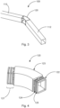
- Fig.3 shows a cable duct 100 with two linear longitudinal sections 110, 112, which are connected to each other by means of a knee connector 120.
- a cable duct with a desired shape or a desired course within a composite panel can be produced from several linear longitudinal sections. Even if in Fig.3 two longitudinal sections 110, 112 and a knee connector 120 are shown, the cable duct can be made from a plurality of linear longitudinal sections and knee connectors arranged between them.
- Fig.4 shows a detailed view of the knee connector 120.
- the knee connector 120 has a first connecting section 121, a second connecting section 122 and a middle section 123 arranged therebetween.
- the knee connector is made of plastic, for example by means of a 3D printing process, and is preferably a one-piece element.
- the knee connector is essentially rigid and retains its shape as long as it is not stressed beyond the strength limits of the material.
- the knee connector follows a uniform radius of curvature, but can also have an elliptical or oval shape in which the curvature value changes between the two ends of the knee connector.
- the knee connectors can be manufactured with a desired radius of curvature or curvature profile.
- the curved connector has a constant cross-section in its interior, ie there are no abrupt changes (in the sense of projections extending from the wall towards the interior) in the walls surrounding the interior.
- the connecting sections have a smaller wall thickness compared to the middle section. Under the condition a constant cross-section of the interior, the outer circumference of the connecting sections is smaller than the outer circumference of the middle section.
- rings 124, 125 are arranged on the connecting sections. These are material projections which extend as a closed ring around the entire outer circumference of the connecting section in the circumferential direction.
- the rings 124, 125 are spaced apart from one another in the longitudinal direction of the cable duct.
- Fig.5 shows a variant of a connection between the connecting section 121 of a knee connector and a longitudinal section 110. For reasons of clarity, Fig.5 not all details of the knee connector are shown. However, it should be understood that the connecting section 121 and the middle section 123 are components of the knee connector 120 of Fig.4 or a knee connector according to any embodiment.
- the wall thickness of the connecting section 121 is reduced in comparison to the wall thickness of the middle section 123, so that the outer circumference of the connecting section 121 is smaller than the outer circumference of the middle section 123.
- the connecting section is inserted into this widened area of the longitudinal section. This way, sudden changes in the internal cross-section of the installed cable duct can be avoided.
- Fig.6 shows a composite panel 10 which is prepared for the insertion of a cable duct or a longitudinal section.
- the composite panel 10 is a composite panel as already described with reference to Fig. 2 so that a repeated description of the elements described there is omitted.
- the cover layer 20 is removed locally, e.g. by milling.
- the cavity is lined with filling material 44 on the side, i.e. towards the core layer 40.
- This filling material 44 can be adhesive material which bonds the cable duct to the core layer.
- This preparation of the composite panel can make it possible to fold or bend the composite panel along the cavity 42, as shown in Fig.7 shown.
- Fig.7 shows the composite panel 10 with a longitudinal section 114 introduced into the cavity 42.
- the longitudinal section 114 has a substantially trapezoidal cross-section.
- the side surface 102 which faces the lower cover layer 30 and is glued to it, is longer than the opposite side surface 104.
- the side surfaces 102, 104 are curved according to a predetermined radius of curvature.
- the side surface 104 is covered by a surface layer 115.
- Fig.8 shows a composite panel 10 which is folded or bent in two places.
- a cable duct 100 runs vertically through the composite panel 10.
- a consumer 90 in this case a monitor
- the cable duct extends in a vertical direction and passes the two fold lines 60.
- Other elements can be attached to the composite panel, but these are not necessarily relevant for the cable duct.
- Fig.9 shows the design of the composite panel 10 at a fold line 60 and in the area of a cable duct.
- a cavity with partially slanted side surfaces is introduced into the composite panel, e.g. milled.
- This cavity can also be referred to as a folding slot 62 and enables the composite panel to be folded or bent at this point.
- the slanted sections of the sides of the cavity lie flat against one another. The sides can then be glued at this point.
- the width of the cavity and the angle of inclination of the slanted sides determine the folding angle of the composite panel.
- a cable duct 100 runs in the composite panel transversely to the fold line. A cable can be routed through this cable duct 100 even after the composite panel has been folded.
- a liquid adhesive is introduced into the folding slot 62.
- This adhesive must not penetrate into the cable duct 100, otherwise it will harden there and can prevent or at least make it difficult to insert cables.
- a folding line connector 130 is placed at the location of the cable duct 100, as shown in Fig.10 shown.
- Fig.10 shows a perspective view of a composite panel 10 with folding slot 62 and cable duct 100.
- the beveled connecting surfaces 64 of the folding slot are also shown.
- a folding line connector 130 is introduced at the intersection point between the folding slot 62 and the cable duct 100.
- the folding line connector 130 is preferably a one-piece element which is angled and corresponds to the intended folding angle of the composite panel 10 after the folding process.
- the folding line connector 130 has a channel-like connection which connects the cable duct 100 transversely to the folding slot 62.
- the folding line connector 130 also seals the cable duct 100 against the ingress of adhesive when adhesive is filled into the folding slot 62.
- a surface 22 of the first cover layer of the composite panel 10 has a recess or depression 24 at the intersection point between the folding slot 62 and the cable duct 100.
- a support surface 46 At the bottom of this depression 24 is a support surface 46.
- the depression 24 serves to ensure that the fold line connector 130 does not protrude above the surface 22.
- the fold line connector 130 can be glued to the support surface 46 and held in position.
- Fig. 11 shows a composite panel 10 with a folding slot 62 into which the folding line connector 130 is inserted. Now adhesive can be poured into the folding slot 62 and the composite panel can be brought into the desired folded state.
- Fig. 12 shows the composite panel of the Fig. 11 after folding.
- the connecting surfaces 64 touch each other and form a fold line 60 and the folding slot 62 forms a space filled with adhesive only in the area of its lower side.
- the folding angle of the composite panel 10 corresponds to the angle of the fold line connector, which is integrated into the surface of the composite panel.
- Fig. 13 shows a detailed view of the fold line connector 130.
- the fold line connector 130 has side surfaces 134 which seal the cable duct against the folding slot.
- the fold line connector 130 has a circumferential collar 132 which is mounted on the support surface 46 (see Fig.10 ) rests on.
- a triangular elevation also: wedge 1366 is attached to the side surface 134 (on both side surfaces).
- the wedge 136 seals the folding slot 62 after the folding process of the composite panel 10.
- the folding slot 62 also forms a triangle after folding the composite panel, which essentially corresponds in shape and size to the wedge 136.
- the side surfaces 134 also serve as an adhesive surface.
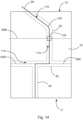
- Fig. 14 shows an example of the modularity of the cable duct 100 in connection with a composite panel 10.
- Fig. 14 not the cable duct, but the cavities 42 in the composite panel are shown. The cavities are shown with dashed lines.
- a linear cavity extends vertically upwards.
- a single linear longitudinal section of a cable duct is inserted into this cavity, as in Fig.1 shown.
- One of the longitudinal sections 110, 112 made of Fig.3 The first vertical cavity meets a horizontal cavity.
- a longitudinal section 114 can be inserted into the horizontal cavity as shown in Fig.7 shown.
- a second vertically running cavity adjoins the horizontally running cavity.
- a longitudinal section 112 can be provided as shown in Fig.3 shown. This is followed by a curved section and another linearly extending cavity.
- a knee connector 120 is typically arranged, to which a further longitudinal section 110 is connected.
- a line 50 can be guided from the lower edge 11 to the upper edge 12.
- the line 50 it is also possible for the line 50 to be led out of the composite panel at an outlet point between the lower edge 11 and the upper edge 12.
- the horizontally extending cavity can be arranged along a first fold line 60A.
- the first fold line 60A marks a fold line of the composite panel 10, as already shown by way of example in Fig.8
- the horizontally extending cavity and the section of the cable duct arranged therein can be designed as shown with reference to Fig.7 described.
- a second fold line 60B is arranged at a distance from the first fold line 60A.
- the second fold line crosses the second vertically extending cavity at a location where a fold line connector 130 is arranged.
- a fold line connector 130 For details of the fold line connector 130, please refer to the Fig. 10 to Fig. 13 and the corresponding description.
Landscapes
- Engineering & Computer Science (AREA)
- Architecture (AREA)
- Civil Engineering (AREA)
- Structural Engineering (AREA)
- Mechanical Engineering (AREA)
- Chemical & Material Sciences (AREA)
- Composite Materials (AREA)
- Details Of Indoor Wiring (AREA)
Description
- Die vorliegende Beschreibung betrifft im Allgemeinen Verbundplatten mit Kabelkanälen bzw. allgemein Verbundplatten mit Hohlräumen zum Aufnehmen und Führen von Leitungen oder eines Mediums.
- Verbundplatten bestehen im Allgemeinen aus einem Kern oder einer Kernschicht und zwei Deckschichten. Die Kernschicht ist zwischen den beiden Deckschichten angeordnet und mit diesen verklebt. Die Kernschicht ist bevorzugt als Wabenstruktur ausgestaltet. Die Wabenstruktur kann verstärkt sein, beispielweise mit einem Harz getränkt. Die Deckschichten sind mit der Kernschicht verklebt. Auf diese Weise wird eine Verbundplatte mit einem sehr guten Festigkeits-GewichtsVerhältnis bereitgestellt, d.h. die Verbundplatte weist eine hohe mechanische Festigkeit bei einem sehr niedrigen Gewicht auf. Somit eignen sich solche Verbundplatten insbesondere für die Verwendung im Leichtbau, beispielsweise im Fahrzeugbau, insbesondere dem Luftfahrzeugbau.
- Der allgemeine Aufbau einer solchen Verbundplatte mit Kernschicht und zwei Deckschichten auf gegenüberliegenden Seiten der Kernschicht ist beispielsweise in
DE 20 2018 107 378 U1 gezeigt. - Beispielsweise werden Verbundplatten im Luftfahrzeugbau als Boden- oder Wandpanel verwendet. Es kann gefordert sein, einen Führungsschacht oder Kanal in einer Verbundplatte bereitzustellen, um elektrische Leitungen oder allgemein Kabel oder Leitungen durch die Verbundplatte zu führen. Damit ein Kanal in einer Verbundplatte nicht zu einer übermäßigen strukturellen Schwächung führt, müssen besondere Maßnahmen um den Kanal herum getroffen werden.
-
CN 110 649 533 A beschreibt eine Kabelkanalvorrichtung, mit einem Befestigungsblock, dessen Enden mit einer Anschlussplatte verbunden sind, eine Anschlussplatte, deren oberes Ende und unteres Ende mit einer Anschlussnut versehen ist, und eine Abschlussplatte, deren beide Enden mit dem Anschlussblock verbunden sind. Die Vorrichtung hat einen Befestigungsblock, dessen oberes Ende und unteres Ende mit mehreren Kabelschnallen verbunden ist, die mit einer C-förmigen Streifenschnalle verbunden ist, wobei die Kabelschnalle größer ist als eine Öffnungsbreite der C-förmigen Streifenschnalle. Die beiden Enden des Befestigungsblocks sind mit einer Verbindungsplatte verbunden. Ein oberes Ende und das untere Ende der Verbindungsplatte sind mit einer Verbindungsnut ausgebildet. Zwei Enden einer Schließplatte sind mit einem Verbindungsblock verbunden. Ein Gleitkern wird auf einen Kabelkanal aufgesetzt. Eine innere Seitenwand eines Drehkörpers ist mit einer Gummischicht befestigt, die mit einem Gummiblumenmuster fixiert ist. - Es kann als Aufgabe betrachtet werden, den Aufwand für das Integrieren von Leitungskanälen in eine Verbundplatte zu reduzieren.
- Diese Aufgabe wird gelöst durch den Gegenstand des unabhängigen Anspruchs. Weitere Ausführungsformen ergeben sich aus den abhängigen Ansprüchen sowie aus der folgenden Beschreibung.
- Gemäß einem ersten Aspekt ist eine Verbundplatte aufweisend eine Kernschicht, eine erste Deckschicht und eine zweite Deckschicht sowie einen Kabelkanal angegeben. Die Kernschicht ist zwischen der ersten Deckschicht und der zweiten Deckschicht angeordnet und mit der ersten Deckschicht und der zweiten Deckschicht verbunden. Ein Hohlraum erstreckt sich in der Kernschicht, wobei der Kabelkanal in dem Hohlraum angeordnet ist und wobei der Kabelkanal eine erste Seitenfläche und eine der ersten Seitenfläche gegenüberliegende zweite Seitenfläche aufweist, wobei die erste Seitenfläche mit der ersten Deckschicht verbunden ist und wobei die zweite Seitenfläche mit der zweiten Deckschicht verbunden ist. Der Hohlraum erstreckt sich von einer ersten Kante (Eintrittskante) der Verbundplatte zu einer zweiten Kante (Austrittskante) der Verbundplatte. Der Kabelkanal stellt eine Führung von der Eintrittskante zu der Austrittskante bereit. Die gesamte erste Seitenfläche liegt an der ersten Deckschicht an. Die gesamte zweite Seitenfläche liegt an der zweiten Deckschicht an.
- Bei der Verbundplatte handelt es sich erfindungsgemäß um eine Leichtbauplatte mit einem sehr leichten Kern, der zwischen zwei Decklagen angeordnet ist. Der Kern besteht aus einem sehr leichten Material und ist ausgelegt, Druckkräfte in Richtung der Normalen der Verbundplatte sowie aus einer Durchbiegung in Folge solcher Druckkräfte resultierende Kräfte (Schubkräfte) aufzunehmen. Der Kern kann beispielsweise eine Wabenstruktur oder ein Kunststoffschaum sein. Die Decklagen nehmen Zug- und Druckkräfte in der Ebene der Verbundplatte auf. Somit kann eine Verbundplatte bei einem sehr niedrigen Eigengewicht sehr hohen Belastungen standhalten.
- In der Kernschicht ist ein Hohlraum angeordnet, der einem vorgegebenen Verlauf folgt. Der Hohlraum kann einen linearen oder gekrümmten Verlauf haben und erstreckt sich von einer Kante (Eintrittskante) der Verbundplatte zu einer anderen Kante (Austrittskante) der Verbundplatte. Der Hohlraum ist eine Ausnehmung in der Kernschicht und erstreckt sich entlang der Plattenebene.
- In dem Hohlraum ist ein Kabelkanal angeordnet. Der Kabelkanal dient dazu, eine Führung innerhalb der Verbundplatte von der Eintrittskante zu der Austrittskante bereitzustellen. Die Führung kann genutzt werden, um Leitungen (beispielsweise elektrische pneumatische, hydraulische Leitungen) oder ein Medium (beispielsweise ein Gas oder ein Fluid) von der Eintrittskante zu der Austrittskante durch die Verbundplatte zu führen.
- Zwei gegenüberliegende Seitenflächen des Kabelkanals sind mit den einander gegenüberliegenden Deckschichten der Verbundplatte verbunden, beispielsweise verklebt. Das heißt, dass sich der Kabelkanal zwischen den Deckschichten über die gesamte Höhe der Kernschicht erstreckt. Der Kabelkanal ist also nur seitlich von der Kernschicht umgeben bzw. grenzt hieran nur seitlich an.
- Erfindungsgemäß ist der Kabelkanal ein Vierkantrohr, das in die Verbundplatte integriert ist. In dem Vierkantrohr können dann Leitungen oder ein Medium transportiert werden.
- Gemäß einer Ausführungsform ist die erste Seitenfläche unmittelbar mit der ersten Deckschicht verklebt und die zweite Seitenfläche ist unmittelbar mit der zweiten Deckschicht verklebt.
- Durch diesen Aufbau behält die Verbundplatte eine höchstmögliche strukturelle Festigkeit.
- Gemäß einer weiteren Ausführungsform ist die erste Seitenfläche und die zweite Seitenfläche planar.
- Somit liegen die erste und die zweite Seitenfläche flächig an jeweils einer Deckschicht an. Erfindungsgemäß liegt die gesamte erste Seitenfläche und die gesamte zweite Seitenfläche an der jeweiligen Deckschicht an.
- Gemäß einer weiteren Ausführungsform hat der Kabelkanal einen rechteckigen Querschnitt, wobei eine dritte Seitenfläche die erste Seitenfläche und die zweite Seitenfläche verbindet, wobei eine vierte Seitenfläche der dritten Seitenfläche gegenüberliegt und die erste Seitenfläche und die zweite Seitenfläche verbindet, und wobei die dritte Seitenfläche und die vierte Seitenfläche mit der Kernschicht verklebt sind.
- Der Kabelkanal kann in einer Ausführungsform einen quadratischen Querschnitt haben. Die an der Kernschicht anliegenden Seitenflächen (die dritte und die vierte Seitenfläche) müssen nicht zwingend planar sein. Vielmehr können diese Seitenflächen auch gekrümmt sein.
- Gemäß einer weiteren Ausführungsform weist der Kabelkanal einen ersten Längsabschnitt und einen zweiten Längsabschnitt auf.
- Der Kabelkanal kann aus einer Mehrzahl von Abschnitten zusammengesetzt sein. Somit kann ein modulares Konzept für den Kabelkanal umgesetzt werden. Der erste Längsabschnitt kann linear verlaufen, ebenso der zweite Längsabschnitt. Insbesondere kann der Kabelkanal aus einer Mehrzahl von linearen Längsabschnitten zusammengesetzt werden, wobei zwischen den linearen Längsabschnitten einzelne Kopplungselemente angeordnet sind, welche jeweils zwei Längsabschnitte miteinander verbinden. Die Kopplungselemente können auch gewinkelt oder gebogen sein, so dass der Kabelkanal insgesamt einen gewünschten Verlauf innerhalb der Verbundplatte abbilden kann.
- Gemäß einer weiteren Ausführungsform weist die Verbundplatte weiterhin einen Knieverbinder auf, wobei der Knieverbinder mit dem ersten Längsabschnitt und dem zweiten Längsabschnitt verbunden ist.
- Bei dem Knieverbinder handelt es sich um eine Variante des oben angesprochenen und zwischen zwei Längsabschnitten angeordneten Kopplungselements. Der Knieverbinder ist gebogen oder gekrümmt, so dass die beiden mit den Knieverbinder verbundenen Längsabschnitte einen Knick formen.
- Gemäß einer weiteren Ausführungsform weist der Knieverbinder einen ersten Verbindungsabschnitt, einen zweiten Verbindungsabschnitt und einen zwischen dem ersten Verbindungsabschnitt und dem zweiten Verbindungsabschnitt angeordneten Mittelabschnitt auf, wobei der erste Verbindungsabschnitt mit dem ersten Längsabschnitt verbunden ist und der zweite Verbindungsabschnitt mit dem zweiten Längsabschnitt verbunden ist, wobei der erste Verbindungsabschnitt eine Mehrzahl von umlaufenden Ringen aufweist, welche sich in Umfangsrichtung um einen gesamten Umfang des Verbindungsabschnitts erstrecken.
- Die Verbindungsabschnitte haben einen kleineren Außenumfang als der Mittelabschnitt, so dass die Verbindungsabschnitte in die miteinander zu verbindende Längsabschnitte des Kabelkanals eingesteckt werden können. Die Ringe haben die Funktion, die Verbindungsabschnitte mit einer Innenfläche der Längsabschnitte dicht zu verschließen, so dass beispielsweise ein flüssiger Kleber, welcher verwendet wird, um den Kabelkanal mit der Kernschicht und/oder den Deckschichten zu verkleben, nicht in den Kabelkanal eindringt und diesen für Leitungen unpassierbar macht oder ein Hindernis darstellt. Es können beispielsweise zwei oder mehr voneinander beabstandete Ringe an jedem Verbindungsabschnitt angeordnet sein. Die Ringe sind in Längsrichtung des Verbindungsabschnitts voneinander beabstandet.
- Gemäß einer weiteren Ausführungsform weist die Verbundplatte weiterhin einen dritten Längsabschnitt auf, wobei der dritte Längsabschnitt quer zu dem ersten Längsabschnitt oder dem zweiten Längsabschnitt verläuft und damit verbunden ist.
- Der dritte Längsabschnitt kann ebenfalls einen rechteckigen Querschnitt haben und der erste oder der zweite Längsabschnitt sind an den dritten Längsabschnitt an einer Seitenfläche des dritten Längsabschnitts angekoppelt. Hierzu kann eine Seitenfläche des dritten Längsabschnitts eine Öffnung aufweisen, welche beispielsweise dem Querschnitt des ersten oder zweiten Längsabschnitts entspricht.
- Gemäß einer weiteren Ausführungsform ist in der Verbundplatte ein Faltschlitz angeordnet, entlang dessen die Verbundplatte um einen bestimmten Faltwinkel gefaltet ist, wobei der Kabelkanal quer zu dem Faltschlitz verläuft und wobei an einem Kreuzungspunkt des Faltschlitzes mit dem Kabelkanal ein Faltlinienverbinder angeordnet ist, der den Kabelkanal von dem Faltschlitz separiert.
- In bestimmten Anwendungsfällen kann es gewünscht sein, dass die Verbundplatte nicht nur ein planares Element ist, sondern eine oder mehrere Faltungen enthält. Eine Faltung verläuft entlang einer Faltlinie. Typischerweise wird entlang der Faltlinie ein Faltschlitz angebracht, beispielsweise indem ein Teil einer Deckschicht und der Kernschicht entfernt wird, z.B. durch Fräsen. Die Verbundplatte kann dann um die zweite Deckschicht gefaltet werden. Die Breite des Faltschlitzes hat Einfluss auf den Faltwinkel. Der Faltschlitz kann zwei Verbundplattenabschnitte voneinander trennen und ermöglicht es, dass ein erster Verbundplattenabschnitt auf einer Seite des Faltschlitzes mit Bezug zu einem zweiten Verbundplattenabschnitt auf der anderen Seite des Faltschlitzes geknickt oder geschwenkt wird.
- Es kann erforderlich sein, einen Kabelkanal durch einen Faltschlitz zu führen, also von dem ersten Verbundplattenabschnitt in den zweiten Verbundplattenabschnitt. Dies wird ermöglicht, indem ein Faltlinienverbinder in den Faltschlitz eingebracht wird und in den beiden Verbundplattenabschnitten jeweils ein Längsabschnitt des Kabelkanals bis zu dem Faltlinienverbinder verläuft und sich hieran anschließt.
- Gemäß einer weiteren Ausführungsform ist in einer Oberfläche der ersten Deckschicht eine Vertiefung mit einer Auflagefläche angeordnet und ein Kragen des Faltlinienverbinders liegt in der Vertiefung auf der Auflagefläche auf und schließt mit der Oberfläche der ersten Deckschicht bündig ab.
- Zusammengefasst und als abschließendes Beispiel wird eine Verbundplatte mit einem modularen Kabelkanal beschrieben. Der Kabelkanal erstreckt sich durch die Verbundplatte und weist beispielsweise lineare Längsabschnitte, Knieverbinder und Faltlinienverbinder auf. Hierdurch kann ein gewünschter Verlauf des Kabelkanals in der Verbundplatte dargestellt werden. Weiterhin ist der Kabelkanal auf beliebige Geometrien der Verbundplatte anpassbar.
- Nachfolgend wird anhand der beigefügten Zeichnungen näher auf Ausführungsbeispiele eingegangen. Die Darstellungen sind schematisch und nicht maßstabsgetreu. Gleiche Bezugszeichen beziehen sich auf gleiche oder ähnliche Elemente. Es zeigen:
- Fig. 1
- eine schematische Darstellung eines Kabelkanals.
- Fig. 2
- eine schematische Darstellung einer Verbundplatte.
- Fig. 3
- eine schematische Darstellung eines Kabelkanals.
- Fig. 4
- eine schematische Darstellung eines Knieverbinders.
- Fig. 5
- eine schematische Darstellung einer Verbindung zwischen einem Längsabschnitt und einem Knieverbinder.
- Fig. 6
- eine schematische Darstellung einer Verbundplatte mit einem Hohlraum in einem ungefalteten Zustand der Verbundplatte.
- Fig. 7
- eine schematische Darstellung einer Verbundplatte mit einem Kabelkanal.
- Fig. 8
- eine schematische Darstellung einer Verbundplatte.
- Fig. 9
- eine schematische Darstellung einer Verbundplatte mit Faltschlitz in einem ungefalteten Zustand der Verbundplatte.
- Fig. 10
- eine schematische Darstellung einer Verbundplatte mit Faltschlitz und Faltlinienverbinder in einem ungefalteten Zustand der Verbundplatte.
- Fig. 11
- eine schematische Darstellung einer Verbundplatte mit Faltschlitz und Faltlinienverbinder in einem ungefalteten Zustand der Verbundplatte.
- Fig. 12
- eine schematische Darstellung einer Verbundplatte mit Faltschlitz und Faltlinienverbinder.
- Fig. 13
- eine schematische Darstellung eines Faltlinienverbinder.
- Fig. 14
- eine schematische Darstellung einer Verbundplatte mit einem beispielhaften Verlauf von Hohlräumen für einen Kabelkanal und einer darin verlaufenden Leitung.
-
Fig. 1 zeigt einen Kabelkanal 100. Der Kabelkanal 100 ist als Vierkantrohr mit rechteckigem Querschnitt ausgestaltet. Der Kabelkanal 100 wird gebildet von vier Seitenwänden 102, 104, 106, 108. In diesem Beispiel verläuft der Kabelkanal linear. Wie im Folgenden beschrieben, können mehrere lineare Abschnitte mit Hilfe von gekrümmten Koppelelementen verbunden werden, um einen gewünschten Verlauf des gesamten Kabelkanals innerhalb einer Verbundplatte zu ermöglichen. - Der Kabelkanal 100 kann aus einem Kunststoff hergestellt sein. Bevorzugt ist der Kabelkanal aus einem faserverstärkten Kunststoff hergestellt. Alternativ kann der Kabelkanal 100 aus harzgetränkten Glasfasern hergestellt sein. Die Außenflächen des Kabelkanals können eine vorgegebene Rauheit aufweisen. Dies kann für das Verkleben des Kabelkanals mit den Deckschichten und der Kernschicht vorteilhaft sein.
-
Fig. 2 zeigt eine Schnittdarstellung einer Verbundplatte 10 mit einer Kernschicht 40, welche zwischen zwei planaren Deckschichten 20, 30 angeordnet und mit diesen verbunden, beispielsweise verklebt, ist. Der Kabelkanal ist auch mit der Kernschicht verbunden, beispielsweise verklebt. Die erste Seitenfläche 102 ist mit der unteren Deckschickt 30 verklebt. Die zweite Seitenfläche 104 ist mit der oberen Deckschicht 20 verklebt. Die dritte Seitenfläche 106 ist mit der Kernschicht verklebt. Die vierte Seitenfläche 108 ist mit der Kernschicht verklebt. - Wie der
Fig. 2 entnommen werden kann, entspricht die Höhe des Kabelkanals 100 dem Abstand zwischen den Deckschichten 20, 30 und somit der Höhe der Kernschicht 40. Zwischen den Seitenflächen 106, 108 und der Kernschicht ist ebenfalls eine Klebeschicht (nicht dargestellt) angeordnet, um den Kabelkanal 100 mit der Kernschicht zu verkleben. -
Fig. 3 zeigt einen Kabelkanal 100 mit zwei linearen Längsabschnitten 110, 112, welche mittels eines Knieverbinders 120 miteinander verbunden sind. Somit kann aus mehreren linearen Längsabschnitten ein Kabelkanal mit einer gewünschten Form oder einem gewünschten Verlauf innerhalb einer Verbundplatte hergestellt werden. Auch wenn inFig. 3 zwei Längsabschnitte 110, 112 und ein Knieverbinder 120 gezeigt sind, kann der Kabelkanal aus einer Vielzahl von linearen Längsabschnitten und jeweils dazwischen angeordneten Knieverbindern hergestellt sein. -
Fig. 4 zeigt eine Detailansicht des Knieverbinders 120. Der Knieverbinder 120 weist einen ersten Verbindungsabschnitt 121, einen zweiten Verbindungsabschnitt 122 und einen dazwischen angeordneten Mittelabschnitt 123 auf. Der Knieverbinder ist aus Kunststoff hergestellt, beispielsweise mittels eines 3D-Druckverfahrens, und ist bevorzugt ein einstückiges Element. Der Knieverbinder ist im Wesentlichen starr und behält seine Form bei, solange er nicht über die Festigkeitsgrenzen des Materials hinaus beansprucht wird. Der Knieverbinder folgt einem gleichmäßigen Krümmungsradius, kann allerdings auch eine elliptische oder ovale Form haben, bei der sich der Krümmungswert zwischen den beiden Enden des Knieverbinders verändert. Die Knieverbinder können mit einem gewünschten Krümmungsradius oder Krümmungsverlauf hergestellt werden. - In einer Variante hat der Krümmungsverbinder in seinem Inneren hat einen gleichbleibenden Querschnitt, d.h. es gibt keine abrupten Änderungen (im Sinne von Vorsprüngen, die sich aus der Wand in Richtung Innenraum erstrecken) der den Innenraum umgebenden Wände. Die Verbindungsabschnitte haben im Vergleich zu dem Mittelabschnitt eine geringere Wandstärke. Unter der Maßgabe eines gleichbleibenden Querschnitts des Innenraums ist damit der Außenumfang der Verbindungsabschnitte kleiner als der Außenumfang des Mittelabschnitts. Diese Ausgestaltung vereinfacht es, den Knieverbinder mit den Längsabschnitten 110, 112 zu verbinden. Eine Variante hierfür wird in
Fig. 5 gezeigt. - An den Verbindungsabschnitten sind mehrere Ringe 124, 125 angeordnet. Hierbei handelt es sich um Materialvorsprünge, welche sich als geschlossener Ring um den gesamten Außenumfang des Verbindungsabschnitts in Umfangsrichtung erstrecken. Die Ringe 124, 125 sind in Längsrichtung des Kabelkanals voneinander beabstandet. Wenn ein Verbindungsabschnitt 121, 122 in einem Längsabschnitt 110, 112 des Kabelkanals eingesteckt ist, bilden sich zwischen den Ringen und der Innenwand eines Längsabschnitts kleine Hohlräume. Diese Hohlräume können dazu dienen, einen Flüssigkleber oder ein Harz, mit welchem ein Kabelkanal in der Verbundplatte umgossen wird, aufzunehmen. Soweit Kleber oder Harz an der Verbindungsstelle zwischen Knieverbinder und Längsabschnitt eindringt, härtet dieser in den Hohlräumen zwischen den Ringen 124, 125 aus und dichtet somit den Innenraum des Kabelkanals gegen weiteres Eindringen von Kleber oder Harz ab.
-
Fig. 5 zeigt eine Variante einer Verbindung zwischen dem Verbindungsabschnitt 121 eines Knieverbinders und einem Längsabschnitt 110. Aus Gründen der Übersichtlichkeit sind inFig. 5 nicht alle Details des Knieverbinders gezeigt. Jedoch sollte verstanden werden, dass es sich bei dem Verbindungsabschnitt 121 und dem Mittelabschnitt 123 um Bestandteile des Knieverbinders 120 ausFig. 4 oder eines Knieverbinders gemäß irgendeiner Ausführungsform handeln kann. - Die Wandstärke des Verbindungsabschnitts 121 ist im Vergleich zu der Wandstärke des Mittelabschnitts 123 reduziert, so dass der Außenumfang des Verbindungsabschnitts 121 kleiner ist als der Außenumfang des Mittelabschnitts 123. Umgekehrt ist in dem Endbereich des Längsabschnitts 110, in welchen der Verbindungsabschnitt eingesteckt wird, eine Aufweitung des Innenquerschnitts des Längsabschnitts zu erkennen. Der Verbindungsabschnitt wird in diesen aufgeweiteten Bereich des Längsabschnitts eingesteckt. Somit können sprungartige Veränderungen des Innenquerschnitts des montierten Kabelkanals vermieden werden.
- Es ist selbstverständlich auch möglich, einen Endabschnitt des Verbindungsabschnitts zum Ende hin konisch zulaufen zu lassen und in einen Längsabschnitt des Kabelkanals mit gleichbleibendem Innenquerschnitt einzustecken. Somit verändert sich zwar der Innenquerschnitt des Kabelkanals, allerdings nicht sprunghaft.
-
Fig. 6 zeigt eine Verbundplatte 10, die für das Einlegen eines Kabelkanals oder eines Längsabschnitts vorbereitet ist. Bei der Verbundplatte 10 handelt es sich um eine Verbundplatte wie schon mit Bezug zuFig. 2 beschrieben, so dass auf eine erneute Beschreibung der dort beschriebenen Elemente verzichtet wird. - Die Deckschicht 20 ist örtlich begrenzt entfernt, z.B. durch Fräsen. Gleiches gilt für die Kernschicht 40, so dass ein von außen zugänglicher Hohlraum 42 gebildet wird. Der Hohlraum wird seitlich, also zu der Kernschicht 40 hin, mit Füllmaterial 44 ausgelegt. Bei diesem Füllmaterial 44 kann es sich um Klebematerial handeln, welches den Kabelkanal mit der Kernschicht verklebt. Durch diese Vorbereitung der Verbundplatte kann es ermöglicht werden, eine Faltung oder Knickung der Verbundplatte entlang des Hohlraums 42 vorzunehmen, wie in
Fig. 7 gezeigt. -
Fig. 7 zeigt die Verbundplatte 10 mit einem in den Hohlraum 42 eingeführten Längsabschnitt 114. Der Längsabschnitt 114 hat einen im Wesentlichen trapezförmigen Querschnitt. Die Seitenfläche 102, welche der unteren Deckschicht 30 zugewandt und mit dieser verklebt ist, ist länger als die gegenüberliegende Seitenfläche 104. Die Seitenflächen 102, 104 sind gemäß einem vorgegebenen Krümmungsradius gekrümmt. In dem Beispiel derFig. 7 ist die Seitenfläche 104 von einer Oberflächenlage 115 bedeckt. Dies ist aber eine optionale Ausgestaltung und die Oberflächenlage 115 kann beispielsweise nur verwendet werden, wenn es die auf die erste Deckschicht 20 aufgebrachten Lasten erfordern. -
Fig. 8 zeigt eine Verbundplatte 10, welche an zwei Stellen gefaltet bzw. geknickt ist. Ein Kabelkanal 100 verläuft in diesem Beispiel senkrecht durch die Verbundplatte 10. So kann beispielsweise ein Verbraucher 90 (in diesem Fall ein Monitor) in einem oberen Bereich der Verbundplatte 10 mit elektrischer Energie über ein durch den Kabelkanal 100 verlaufendes Kabel versorgt werden. Der Kabelkanal erstreckt sich in vertikaler Richtung und passiert die beiden Faltlinien 60. An der Verbundplatte können weitere Elemente angebracht sein, die aber für den Kabelkanal nicht zwingend relevant sind. -
Fig. 9 zeigt die Ausgestaltung des Verbundplatte 10 an einer Faltlinie 60 und im Bereich eines Kabelkanals. Ein Hohlraum mit teilweise schräg verlaufenden Seitenflächen wird in die Verbundplatte eingebracht, z.B. eingefräst. Dieser Hohlraum kann auch als Faltschlitz 62 bezeichnet werden und ermöglicht es, die Verbundplatte an dieser Stelle zu falten bzw. zu knicken. Wenn die Verbundplatte gefaltet wird, liegen die schräg verlaufenden Abschnitt der Seiten des Hohlraums flächig aneinander. An dieser Stelle können die Seiten dann verklebt werden. Die Breite des Hohlraums und der Neigungswinkel der schräg verlaufenden Seiten geben den Faltwinkel der Verbundplatte vor. In der Verbundplatte verläuft quer zu der Faltlinie ein Kabelkanal 100. Durch diesen Kabelkanal 100 kann auch nach dem Falten der Verbundplatte eine Leitung geführt werden. - Vor dem Falten der Verbundplatte 10 wird in den Faltschlitz 62 ein flüssiger Kleber eingebracht. Dieser Kleber darf nicht in den Kabelkanal 100 eindringen, ansonsten härtet er dort aus und kann das Einführen von Kabeln verhindern oder mindestens erschweren. Um das Eindringen von Kleber aus dem Faltschlitz 62 in den Kabelkanal 100 zu verhindern, wird an der Stelle des Kabelkanals 100 ein Faltlinienverbinder 130 platziert, wie in
Fig. 10 gezeigt. -
Fig. 10 zeigt eine perspektivische Ansicht auf eine Verbundplatte 10 mit Faltschlitz 62 und Kabelkanal 100. Die angeschrägten Verbindungsflächen 64 des Faltschlitzes sind ebenfalls gezeigt. An der Kreuzungsstelle zwischen dem Faltschlitz 62 und dem Kabelkanal 100 wird ein Faltlinienverbinder 130 eingebracht. Der Faltlinienverbinder 130 ist bevorzugt ein einstückiges Element, welches gewinkelt ist und dem beabsichtigten Faltwinkel der Verbundplatte 10 nach dem Faltvorgang entspricht. Der Faltlinienverbinder 130 hat eine kanalartige Verbindung, welche den Kabelkanal 100 quer zu dem Faltschlitz 62 verbindet. Ebenso dichtet der Faltlinienverbinder 130 den Kabelkanal 100 gegen das Eindringen von Klebstoff ab, wenn Klebstoff in den Faltschlitz 62 gefüllt wird. - Eine Oberfläche 22 der ersten Deckschicht der Verbundplatte 10 hat eine Ausnehmung oder Vertiefung 24 an dem Kreuzungspunkt zwischen Faltschlitz 62 und Kabelkanal 100. Am Boden dieser Vertiefung 24 befindet sich eine Auflagefläche 46. Die Vertiefung 24 dient dazu, dass der Faltlinienverbinder 130 nicht über die Oberfläche 22 herausragt. Der Faltlinienverbinder 130 kann mit der Auflagefläche 46 verklebt und in Position gehalten werden.
-
Fig. 11 zeigt eine Verbundplatte 10 mit Faltschlitz 62, in welchen der Faltlinienverbinder 130 eingesetzt ist. Nun kann Klebstoff in den Faltschlitz 62 eingefüllt und die Verbundplatte in den gewünschten gefalteten Zustand gebracht werden. -
Fig. 12 zeigt die Verbundplatte derFig. 11 nach dem Falten. Die Verbindungsflächen 64 berühren einander und formen eine Faltlinie 60 und der Faltschlitz 62 bildet lediglich im Bereich seiner unteren Seite einen mit Klebstoff gefüllten Raum. Der Faltungswinkel der Verbundplatte 10 entspricht dem Winkel des Faltlinienverbinders, welcher sich in die Oberfläche der Verbundplatte integriert. -
Fig. 13 zeigt eine Detaildarstellung des Faltlinienverbinders 130. Der Faltlinienverbinder 130 weist Seitenflächen 134 auf, welche den Kabelkanal gegenüber dem Faltschlitz abdichten. Der Faltlinienverbinder 130 weist einen umlaufenden Kragen 132 auf, welcher auf der Auflagefläche 46 (sieheFig. 10 ) aufliegt. Weiterhin ist an der Seitenfläche 134 (an beiden Seitenflächen) eine dreieckförmige Erhebung (auch: Keil 136) angebracht. Der Keil 136 dichtet den Faltschlitz 62 nach dem Faltvorgang der Verbundplatte 10 ab. Wie inFig. 12 zu sehen ist, formt der Faltschlitz 62 nach dem Falten der Verbundplatte ebenfalls ein Dreieck, welches in Form und Größe im Wesentlichen dem Keil 136 entspricht. Die Seitenflächen 134 dienen auch als Klebefläche. -
Fig. 14 zeigt beispielhaft die Modularität des Kabelkanals 100 in Verbindung mit einer Verbundplatte 10. Der Übersichtlichkeit halber ist inFig. 14 nicht der Kabelkanal, sondern die Hohlräume 42 in der Verbundplatte gezeigt. Die Hohlräume sind mit gestrichelten Linien gezeigt. - In
Fig. 14 von unten nach oben erstreckt sich zunächst ein linearer Hohlraum senkrecht nach oben. In diesen Hohlraum wird typischerweise ein einzelner linearer Längsabschnitt eines Kabelkanals, wie inFig. 1 gezeigt, eingebracht. In diesen linearen Hohlraum kann auch einer der Längsabschnitte 110, 112 ausFig. 3 eingebracht werden. Der erste senkrechte Hohlraum trifft auf einen horizontal verlaufenden Hohlraum. In den horizontal verlaufenden Hohlraum kann ein Längsabschnitt 114 wie inFig. 7 gezeigt eingebracht werden. Mit etwas seitlichem Versatz zu dem ersten vertikal verlaufenden Hohlraum schließt sich ein zweiter vertikal verlaufender Hohlraum an den horizontal verlaufenden Hohlraum an. In dem zweiten vertikal verlaufenden Hohlraum kann ein Längsabschnitt 112 wie inFig. 3 gezeigt angeordnet werden. Sodann schließt sich ein gekrümmter Abschnitt und ein weiterer linear verlaufender Hohlraum an. In dem gekrümmten Abschnitt ist typischerweise ein Knieverbinder 120 angeordnet, an den sich ein weiterer Längsabschnitt 110 anschließt. Auf diese Weise kann eine Leitung 50 von der unteren Kante 11 zu der oberen Kante 12 geführt werden. Selbstverständlich ist es möglich, dass die Leitung 50 auch an einem Auslasspunkt zwischen der unteren Kante 11 und der oberen Kante 12 aus der Verbundplatte herausgeführt wird. - Der horizontal verlaufende Hohlraum kann entlang einer ersten Faltlinie 60A angeordnet sein. Die erste Faltlinie 60A kennzeichnet eine Faltlinie der Verbundplatte 10, wie dies beispielhaft bereits in
Fig. 8 gezeigt wird. Der horizontal verlaufende Hohlraum und der darin angeordnete Abschnitt des Kabelkanals kann dabei so ausgestaltet sein, wie mit Bezug zuFig. 7 beschrieben. - Eine zweite Faltlinie 60B ist beabstandet von der ersten Faltlinie 60A angeordnet. Die zweite Faltlinie kreuzt den zweiten vertikal verlaufenden Hohlraum an einer Stelle, an welcher ein Faltlinienverbinder 130 angeordnet ist. Für Details zu dem Faltlinienverbinder 130 wird auf die
Fig. 10 bis Fig. 13 sowie die zugehörige Beschreibung verwiesen. - Ergänzend ist darauf hinzuweisen, dass "umfassend" oder "aufweisend" keine anderen Elemente oder Schritte ausschließt und "eine" oder "ein" keine Vielzahl ausschließt. Ferner sei darauf hingewiesen, dass Merkmale oder Schritte, die mit Verweis auf eines der obigen Ausführungsbeispiele beschrieben worden sind, auch in Kombination mit anderen Merkmalen oder Schritten anderer oben beschriebener Ausführungsbeispiele verwendet werden können. Bezugszeichen in den Ansprüchen sind nicht als Einschränkung anzusehen.
-
- 10
- Verbundplatte
- 11
- untere Kante
- 12
- obere Kante
- 20
- erste Deckschicht
- 22
- Oberfläche
- 24
- Vertiefung
- 30
- zweite Deckschicht
- 40
- Kernschicht
- 42
- Hohlraum
- 44
- Füllmaterial
- 46
- Auflagefläche
- 50
- Leitung
- 60
- Faltlinie
- 62
- Faltschlitz
- 64
- Verbindungsfläche
- 90
- Verbraucher
- 100
- Kabelkanal
- 102
- erste Seitenfläche
- 104
- zweite Seitenfläche
- 106
- dritte Seitenfläche
- 108
- vierte Seitenfläche
- 110
- erster Längsabschnitt
- 112
- zweiter Längsabschnitt
- 114
- dritter Längsabschnitt
- 115
- Oberflächenlage
- 120
- Knieverbinder
- 121
- erster Verbindungsabschnitt
- 122
- zweiter Verbindungsabschnitt
- 123
- Mittelabschnitt
- 124
- Ring
- 125
- Ring
- 130
- Faltlinienverbinder
- 132
- Kragen
- 134
- Seitenfläche
- 136
- Keil
Claims (10)
- Verbundplatte (10), aufweisend:eine Kernschicht (40);eine erste Deckschicht (20) und eine zweite Deckschicht (30);einen Kabelkanal (100);wobei die Kernschicht zwischen der ersten Deckschicht und der zweiten Deckschicht angeordnet und mit der ersten Deckschicht und der zweiten Deckschicht verbunden ist;wobei die Verbundplatte (10) eine Leichtbauplatte ist und die Kernschicht (40) ausgelegt ist, Druckkräfte in Richtung der Normalen der Verbundplatte sowie aus einer Durchbiegung in Folge solcher Druckkräfte resultierende Kräfte aufzunehmen, und die erste und zweite Deckschicht (20, 30) ausgestaltet sind, Zug- und Druckkräfte in der Ebene der Verbundplatte aufzunehmen;wobei sich ein Hohlraum (42) in der Kernschicht (40) erstreckt;wobei der Kabelkanal (100) in dem Hohlraum (42) angeordnet ist;wobei der Kabelkanal (100) eine erste Seitenfläche (102) und eine der ersten Seitenfläche gegenüberliegende zweite Seitenfläche (104) aufweist;wobei die erste Seitenfläche (102) mit der ersten Deckschicht (20) verbunden ist;wobei die zweite Seitenfläche (104) mit der zweiten Deckschicht (30) verbunden ist;dadurch gekennzeichnet, dassder Kabelkanal (100) als Vierkantrohr ausgestaltet und in der Verbundplatte integriert ist;sich der Hohlraum (42) von einer ersten als Eintrittskante bezeichneten Kante (11) der Verbundplatte (10) zu einer zweiten als Austrittskante bezeichneten Kante (12) der Verbundplatte (10) erstreckt;der Kabelkanal (100) eine Führung von der Eintrittskante zu der Austrittskante bereitstellt;die gesamte erste Seitenfläche (102) an der ersten Deckschicht (20) anliegt;die gesamte zweite Seitenfläche (104) an der zweiten Deckschicht (30) anliegt.
- Verbundplatte (10) nach Anspruch 1,wobei die erste Seitenfläche (102) unmittelbar mit der ersten Deckschicht (20) verklebt ist;wobei die zweite Seitenfläche (30) unmittelbar mit der zweiten Deckschicht (30) verklebt ist.
- Verbundplatte (10) nach Anspruch 1 oder 2,
wobei die erste Seitenfläche (102) und die zweite Seitenfläche (104) planar sind. - Verbundplatte (10) nach einem der vorhergehenden Ansprüche,wobei der Kabelkanal (100) einen rechteckigen Querschnitt hat;wobei eine dritte Seitenfläche (106) die erste Seitenfläche (102) und die zweite Seitenfläche (104) verbindet;wobei eine vierte Seitenfläche (108) der dritten Seitenfläche (106) gegenüberliegt und die erste Seitenfläche (102) und die zweite Seitenfläche (104) verbindet;wobei die dritte Seitenfläche (106) und die vierte Seitenfläche (108) mit der Kernschicht (40) verklebt sind.
- Verbundplatte (10) nach einem der vorhergehenden Ansprüche,
wobei der Kabelkanal (100) einen ersten Längsabschnitt (110) und einen zweiten Längsabschnitt (112) aufweist; - Verbundplatte (10) nach Anspruch 5,weiterhin aufweisend einen Knieverbinder (120);wobei der Knieverbinder mit dem ersten Längsabschnitt (110) und dem zweiten Längsabschnitt (112) verbunden ist.
- Verbundplatte (10) nach Anspruch 6,wobei der Knieverbinder (120) einen ersten Verbindungsabschnitt (121), einen zweiten Verbindungsabschnitt (122) und einen zwischen dem ersten Verbindungsabschnitt (121) und dem zweiten Verbindungsabschnitt (122) angeordneten Mittelabschnitt (123) aufweist;wobei der erste Verbindungsabschnitt (121) mit dem ersten Längsabschnitt (110) verbunden ist und der zweite Verbindungsabschnitt (122) mit dem zweiten Längsabschnitt (112) verbunden ist;wobei der erste Verbindungsabschnitt (121) eine Mehrzahl von umlaufenden Ringen (124, 125) aufweist, welche sich in Umfangsrichtung um einen gesamten Umfang des Verbindungsabschnitts erstrecken.
- Verbundplatte (10) nach einem der Ansprüche 5 bis 7,weiterhin aufweisend einen dritten Längsabschnitt (114);wobei der dritte Längsabschnitt (114) quer zu dem ersten Längsabschnitt (110) oder dem zweiten Längsabschnitt (112) verläuft und damit verbunden ist.
- Verbundplatte (10) nach einem der vorhergehenden Ansprüche,wobei in der Verbundplatte ein Faltschlitz (62) angeordnet ist, entlang dessen die Verbundplatte um einen bestimmten Faltwinkel gefaltet ist;wobei der Kabelkanal (100) quer zu dem Faltschlitz (62) verläuft;wobei an einem Kreuzungspunkt des Faltschlitzes mit dem Kabelkanal ein Faltlinienverbinder (130) angeordnet ist, der den Kabelkanal (100) von dem Faltschlitz (62) separiert.
- Verbundplatte (10) nach Anspruch 9,wobei in einer Oberfläche (22) der ersten Deckschicht (20) eine Vertiefung (24) mit einer Auflagefläche (46) angeordnet ist;wobei ein Kragen (132) des Faltlinienverbinders (130) in der Vertiefung auf der Auflagefläche (46) aufliegt und mit der Oberfläche (22) der ersten Deckschicht (20) bündig abschließt.
Applications Claiming Priority (1)
| Application Number | Priority Date | Filing Date | Title |
|---|---|---|---|
| DE102020106854.9A DE102020106854A1 (de) | 2020-03-12 | 2020-03-12 | Verbundplatte mit kabelkanal |
Publications (2)
| Publication Number | Publication Date |
|---|---|
| EP3878641A1 EP3878641A1 (de) | 2021-09-15 |
| EP3878641B1 true EP3878641B1 (de) | 2024-08-21 |
Family
ID=74550559
Family Applications (1)
| Application Number | Title | Priority Date | Filing Date |
|---|---|---|---|
| EP21155036.3A Active EP3878641B1 (de) | 2020-03-12 | 2021-02-03 | Verbundplatte mit kabelkanal |
Country Status (2)
| Country | Link |
|---|---|
| EP (1) | EP3878641B1 (de) |
| DE (1) | DE102020106854A1 (de) |
Families Citing this family (1)
| Publication number | Priority date | Publication date | Assignee | Title |
|---|---|---|---|---|
| DE102023107649A1 (de) * | 2023-03-27 | 2024-10-02 | Elbe Flugzeugwerke Gmbh | Falttechnologie für Sandwichplatten und eine entsprechende Sandwichplatte |
Family Cites Families (15)
| Publication number | Priority date | Publication date | Assignee | Title |
|---|---|---|---|---|
| US3993387A (en) | 1974-11-25 | 1976-11-23 | Amerace Corporation | Electrical connector and method of making same |
| US4812193A (en) | 1986-12-22 | 1989-03-14 | Gauron Richard F | Inset panel fastener and method of using |
| DE9105019U1 (de) | 1991-04-24 | 1991-06-20 | Herbich, Wolfgang, Dipl.-Ing., O-8072 Dresden | Verbundplatte |
| DE9209999U1 (de) | 1992-07-24 | 1993-08-26 | Tever GmbH & Co KG, 83022 Rosenheim | Heiz- oder Kühlpaneel |
| US6329493B1 (en) | 1998-10-06 | 2001-12-11 | Bp Corporation North America Inc. | Plumbing articles from poly(aryl ether sulfones) |
| DE10107934A1 (de) | 2001-02-20 | 2002-08-22 | Klaus Droste | Mehrschichtiges Tafelbauelement zur Verwendung im Bau und dessen Herstellungsverfahren |
| AU2003240396A1 (en) | 2002-04-19 | 2003-11-03 | Rosskopf Und Partner Ag | Composite plate |
| DE102005016654B4 (de) | 2005-04-12 | 2008-11-20 | Airbus Deutschland Gmbh | Sandwichelement zur schallabsorbierenden Innenverkleidung von Verkehrsmitteln, insbesondere zur schallabsorbierenden Innenverkleidung von Luftfahrzeugen |
| US8393601B2 (en) | 2008-10-04 | 2013-03-12 | Applied Concepts Aircraft Solutions, Inc. | Vibration isolation fastener insert |
| EP2196308B1 (de) | 2008-12-11 | 2017-10-04 | ALSTOM Transport Technologies | Sandwichplatte mit verbesserter Schallabsorption |
| DE102010013370B8 (de) | 2010-03-30 | 2013-12-12 | Eads Deutschland Gmbh | Wandbauteil für ein Luftfahrzeug |
| PT2781762T (pt) | 2013-03-20 | 2019-01-30 | Ruag Schweiz Ag | Estrutura de suporte leve, método para produção de uma estrutura de suporte leve, painel sanduíche composto e método para produção de um painel sanduíche composto |
| US10266098B1 (en) | 2017-12-21 | 2019-04-23 | Celltech Metals, Inc. | Cargo transportation system including a sandwich panel and a channel |
| CN110649533A (zh) * | 2018-06-26 | 2020-01-03 | 滕银祥 | 一种电缆通道装置 |
| DE202018107378U1 (de) | 2018-12-21 | 2019-01-11 | Elbe Flugzeugwerke Gmbh | Sandwichplatte mit akustischen Dämpfungseigenschaften |
-
2020
- 2020-03-12 DE DE102020106854.9A patent/DE102020106854A1/de active Pending
-
2021
- 2021-02-03 EP EP21155036.3A patent/EP3878641B1/de active Active
Also Published As
| Publication number | Publication date |
|---|---|
| EP3878641A1 (de) | 2021-09-15 |
| DE102020106854A1 (de) | 2021-09-16 |
Similar Documents
| Publication | Publication Date | Title |
|---|---|---|
| DE69911507T2 (de) | Flügelstruktur aus Faserverbundstoff | |
| EP0591705B1 (de) | Schalenbauteil aus Faserverbundwerkstoff | |
| DE102018122813B4 (de) | Fußbodensystem für ein Fahrzeug | |
| DE1750240A1 (de) | Wanddurchfuehrung fuer Rohre,elektrische Kabel od.dgl. | |
| EP1989455B1 (de) | Führungsschiene mit abdeckband für ein linearlager | |
| EP1288077A1 (de) | Innenschale für ein Dachmodul in Sandwich-Bauweise sowie Verfahren zu ihrer Herstellung | |
| EP1108646A2 (de) | Strukturbauteil | |
| EP2374949A1 (de) | Formswchlüssige Verbindungseinrichtung für zwei Bauelemente, insbesondere Solarmodule | |
| EP3354450A1 (de) | Pultrudiertes profil für ein strukturbauteil einer windenergieanlage | |
| DE19753111A1 (de) | Lagerbuchse mit Mittelbund sowie deren Verwendung und Herstellungsverfahren | |
| DE102013205275B3 (de) | Flugzeugrumpfstruktur | |
| EP3678915B1 (de) | Eckverbindung für tragelemente einer seilbahnkabine | |
| EP0082321A2 (de) | Biegefeder aus faserverstärktem Kunststoff und Presswerkzeug für deren Fertigung | |
| EP2786922B1 (de) | Kunststoffkarosserie eines Kraftfahrzeugs aus Kunststoffelementen und entsprechende Verbindungen der Elemente | |
| DE3008287A1 (de) | Bolzen fuer schubstangen | |
| DE102016001293A1 (de) | Zugangstunnelsystem zur überdachten Führung von Personen | |
| EP3521642B1 (de) | Anordnen eines verbundelements an einem bauteil | |
| EP3878641A1 (de) | Verbundplatte mit kabelkanal | |
| EP0250612A1 (de) | Gerüstboden für ein Schnellbaugerüst | |
| DE3106069A1 (de) | Zentriervorrichtung | |
| DE202018102368U1 (de) | Installationsdose | |
| DE102019101783B4 (de) | Flugzeugrumpfstruktur | |
| EP1798186B1 (de) | Aufzugskabine und Verfahren zum Montieren von Wandelementen einer Kabinenwand | |
| DE102016216527B4 (de) | Spantvorrichtung und Anordnung | |
| EP3996891B1 (de) | Wendevorrichtung mit einer zentriervorrichtung |
Legal Events
| Date | Code | Title | Description |
|---|---|---|---|
| PUAI | Public reference made under article 153(3) epc to a published international application that has entered the european phase |
Free format text: ORIGINAL CODE: 0009012 |
|
| STAA | Information on the status of an ep patent application or granted ep patent |
Free format text: STATUS: THE APPLICATION HAS BEEN PUBLISHED |
|
| AK | Designated contracting states |
Kind code of ref document: A1 Designated state(s): AL AT BE BG CH CY CZ DE DK EE ES FI FR GB GR HR HU IE IS IT LI LT LU LV MC MK MT NL NO PL PT RO RS SE SI SK SM TR |
|
| STAA | Information on the status of an ep patent application or granted ep patent |
Free format text: STATUS: REQUEST FOR EXAMINATION WAS MADE |
|
| 17P | Request for examination filed |
Effective date: 20220310 |
|
| RBV | Designated contracting states (corrected) |
Designated state(s): AL AT BE BG CH CY CZ DE DK EE ES FI FR GB GR HR HU IE IS IT LI LT LU LV MC MK MT NL NO PL PT RO RS SE SI SK SM TR |
|
| STAA | Information on the status of an ep patent application or granted ep patent |
Free format text: STATUS: EXAMINATION IS IN PROGRESS |
|
| 17Q | First examination report despatched |
Effective date: 20220504 |
|
| GRAP | Despatch of communication of intention to grant a patent |
Free format text: ORIGINAL CODE: EPIDOSNIGR1 |
|
| STAA | Information on the status of an ep patent application or granted ep patent |
Free format text: STATUS: GRANT OF PATENT IS INTENDED |
|
| GRAJ | Information related to disapproval of communication of intention to grant by the applicant or resumption of examination proceedings by the epo deleted |
Free format text: ORIGINAL CODE: EPIDOSDIGR1 |
|
| STAA | Information on the status of an ep patent application or granted ep patent |
Free format text: STATUS: EXAMINATION IS IN PROGRESS |
|
| GRAP | Despatch of communication of intention to grant a patent |
Free format text: ORIGINAL CODE: EPIDOSNIGR1 |
|
| STAA | Information on the status of an ep patent application or granted ep patent |
Free format text: STATUS: GRANT OF PATENT IS INTENDED |
|
| INTG | Intention to grant announced |
Effective date: 20240523 |
|
| INTC | Intention to grant announced (deleted) | ||
| GRAS | Grant fee paid |
Free format text: ORIGINAL CODE: EPIDOSNIGR3 |
|
| INTG | Intention to grant announced |
Effective date: 20240617 |
|
| GRAA | (expected) grant |
Free format text: ORIGINAL CODE: 0009210 |
|
| STAA | Information on the status of an ep patent application or granted ep patent |
Free format text: STATUS: THE PATENT HAS BEEN GRANTED |
|
| AK | Designated contracting states |
Kind code of ref document: B1 Designated state(s): AL AT BE BG CH CY CZ DE DK EE ES FI FR GB GR HR HU IE IS IT LI LT LU LV MC MK MT NL NO PL PT RO RS SE SI SK SM TR |
|
| REG | Reference to a national code |
Ref country code: GB Ref legal event code: FG4D Free format text: NOT ENGLISH |
|
| REG | Reference to a national code |
Ref country code: CH Ref legal event code: EP |
|
| REG | Reference to a national code |
Ref country code: DE Ref legal event code: R096 Ref document number: 502021004817 Country of ref document: DE |
|
| REG | Reference to a national code |
Ref country code: IE Ref legal event code: FG4D Free format text: LANGUAGE OF EP DOCUMENT: GERMAN |
|
| P01 | Opt-out of the competence of the unified patent court (upc) registered |
Free format text: CASE NUMBER: APP_50262/2024 Effective date: 20240904 |
|
| REG | Reference to a national code |
Ref country code: LT Ref legal event code: MG9D |
|
| REG | Reference to a national code |
Ref country code: NL Ref legal event code: MP Effective date: 20240821 |
|
| PG25 | Lapsed in a contracting state [announced via postgrant information from national office to epo] |
Ref country code: NO Free format text: LAPSE BECAUSE OF FAILURE TO SUBMIT A TRANSLATION OF THE DESCRIPTION OR TO PAY THE FEE WITHIN THE PRESCRIBED TIME-LIMIT Effective date: 20241121 |
|
| PG25 | Lapsed in a contracting state [announced via postgrant information from national office to epo] |
Ref country code: NL Free format text: LAPSE BECAUSE OF FAILURE TO SUBMIT A TRANSLATION OF THE DESCRIPTION OR TO PAY THE FEE WITHIN THE PRESCRIBED TIME-LIMIT Effective date: 20240821 Ref country code: GR Free format text: LAPSE BECAUSE OF FAILURE TO SUBMIT A TRANSLATION OF THE DESCRIPTION OR TO PAY THE FEE WITHIN THE PRESCRIBED TIME-LIMIT Effective date: 20241122 Ref country code: PL Free format text: LAPSE BECAUSE OF FAILURE TO SUBMIT A TRANSLATION OF THE DESCRIPTION OR TO PAY THE FEE WITHIN THE PRESCRIBED TIME-LIMIT Effective date: 20240821 Ref country code: FI Free format text: LAPSE BECAUSE OF FAILURE TO SUBMIT A TRANSLATION OF THE DESCRIPTION OR TO PAY THE FEE WITHIN THE PRESCRIBED TIME-LIMIT Effective date: 20240821 Ref country code: PT Free format text: LAPSE BECAUSE OF FAILURE TO SUBMIT A TRANSLATION OF THE DESCRIPTION OR TO PAY THE FEE WITHIN THE PRESCRIBED TIME-LIMIT Effective date: 20241223 |
|
| PG25 | Lapsed in a contracting state [announced via postgrant information from national office to epo] |
Ref country code: BG Free format text: LAPSE BECAUSE OF FAILURE TO SUBMIT A TRANSLATION OF THE DESCRIPTION OR TO PAY THE FEE WITHIN THE PRESCRIBED TIME-LIMIT Effective date: 20240821 |
|
| PG25 | Lapsed in a contracting state [announced via postgrant information from national office to epo] |
Ref country code: LV Free format text: LAPSE BECAUSE OF FAILURE TO SUBMIT A TRANSLATION OF THE DESCRIPTION OR TO PAY THE FEE WITHIN THE PRESCRIBED TIME-LIMIT Effective date: 20240821 |
|
| PG25 | Lapsed in a contracting state [announced via postgrant information from national office to epo] |
Ref country code: IS Free format text: LAPSE BECAUSE OF FAILURE TO SUBMIT A TRANSLATION OF THE DESCRIPTION OR TO PAY THE FEE WITHIN THE PRESCRIBED TIME-LIMIT Effective date: 20241221 |
|
| PG25 | Lapsed in a contracting state [announced via postgrant information from national office to epo] |
Ref country code: HR Free format text: LAPSE BECAUSE OF FAILURE TO SUBMIT A TRANSLATION OF THE DESCRIPTION OR TO PAY THE FEE WITHIN THE PRESCRIBED TIME-LIMIT Effective date: 20240821 |
|
| PG25 | Lapsed in a contracting state [announced via postgrant information from national office to epo] |
Ref country code: RS Free format text: LAPSE BECAUSE OF FAILURE TO SUBMIT A TRANSLATION OF THE DESCRIPTION OR TO PAY THE FEE WITHIN THE PRESCRIBED TIME-LIMIT Effective date: 20241121 Ref country code: ES Free format text: LAPSE BECAUSE OF FAILURE TO SUBMIT A TRANSLATION OF THE DESCRIPTION OR TO PAY THE FEE WITHIN THE PRESCRIBED TIME-LIMIT Effective date: 20240821 |
|
| PG25 | Lapsed in a contracting state [announced via postgrant information from national office to epo] |
Ref country code: RS Free format text: LAPSE BECAUSE OF FAILURE TO SUBMIT A TRANSLATION OF THE DESCRIPTION OR TO PAY THE FEE WITHIN THE PRESCRIBED TIME-LIMIT Effective date: 20241121 Ref country code: PT Free format text: LAPSE BECAUSE OF FAILURE TO SUBMIT A TRANSLATION OF THE DESCRIPTION OR TO PAY THE FEE WITHIN THE PRESCRIBED TIME-LIMIT Effective date: 20241223 Ref country code: PL Free format text: LAPSE BECAUSE OF FAILURE TO SUBMIT A TRANSLATION OF THE DESCRIPTION OR TO PAY THE FEE WITHIN THE PRESCRIBED TIME-LIMIT Effective date: 20240821 Ref country code: NO Free format text: LAPSE BECAUSE OF FAILURE TO SUBMIT A TRANSLATION OF THE DESCRIPTION OR TO PAY THE FEE WITHIN THE PRESCRIBED TIME-LIMIT Effective date: 20241121 Ref country code: NL Free format text: LAPSE BECAUSE OF FAILURE TO SUBMIT A TRANSLATION OF THE DESCRIPTION OR TO PAY THE FEE WITHIN THE PRESCRIBED TIME-LIMIT Effective date: 20240821 Ref country code: LV Free format text: LAPSE BECAUSE OF FAILURE TO SUBMIT A TRANSLATION OF THE DESCRIPTION OR TO PAY THE FEE WITHIN THE PRESCRIBED TIME-LIMIT Effective date: 20240821 Ref country code: IS Free format text: LAPSE BECAUSE OF FAILURE TO SUBMIT A TRANSLATION OF THE DESCRIPTION OR TO PAY THE FEE WITHIN THE PRESCRIBED TIME-LIMIT Effective date: 20241221 Ref country code: HR Free format text: LAPSE BECAUSE OF FAILURE TO SUBMIT A TRANSLATION OF THE DESCRIPTION OR TO PAY THE FEE WITHIN THE PRESCRIBED TIME-LIMIT Effective date: 20240821 Ref country code: GR Free format text: LAPSE BECAUSE OF FAILURE TO SUBMIT A TRANSLATION OF THE DESCRIPTION OR TO PAY THE FEE WITHIN THE PRESCRIBED TIME-LIMIT Effective date: 20241122 Ref country code: FI Free format text: LAPSE BECAUSE OF FAILURE TO SUBMIT A TRANSLATION OF THE DESCRIPTION OR TO PAY THE FEE WITHIN THE PRESCRIBED TIME-LIMIT Effective date: 20240821 Ref country code: ES Free format text: LAPSE BECAUSE OF FAILURE TO SUBMIT A TRANSLATION OF THE DESCRIPTION OR TO PAY THE FEE WITHIN THE PRESCRIBED TIME-LIMIT Effective date: 20240821 Ref country code: BG Free format text: LAPSE BECAUSE OF FAILURE TO SUBMIT A TRANSLATION OF THE DESCRIPTION OR TO PAY THE FEE WITHIN THE PRESCRIBED TIME-LIMIT Effective date: 20240821 |
|
| PG25 | Lapsed in a contracting state [announced via postgrant information from national office to epo] |
Ref country code: RO Free format text: LAPSE BECAUSE OF FAILURE TO SUBMIT A TRANSLATION OF THE DESCRIPTION OR TO PAY THE FEE WITHIN THE PRESCRIBED TIME-LIMIT Effective date: 20240821 Ref country code: SM Free format text: LAPSE BECAUSE OF FAILURE TO SUBMIT A TRANSLATION OF THE DESCRIPTION OR TO PAY THE FEE WITHIN THE PRESCRIBED TIME-LIMIT Effective date: 20240821 Ref country code: DK Free format text: LAPSE BECAUSE OF FAILURE TO SUBMIT A TRANSLATION OF THE DESCRIPTION OR TO PAY THE FEE WITHIN THE PRESCRIBED TIME-LIMIT Effective date: 20240821 |
|
| PG25 | Lapsed in a contracting state [announced via postgrant information from national office to epo] |
Ref country code: EE Free format text: LAPSE BECAUSE OF FAILURE TO SUBMIT A TRANSLATION OF THE DESCRIPTION OR TO PAY THE FEE WITHIN THE PRESCRIBED TIME-LIMIT Effective date: 20240821 |
|
| PG25 | Lapsed in a contracting state [announced via postgrant information from national office to epo] |
Ref country code: CZ Free format text: LAPSE BECAUSE OF FAILURE TO SUBMIT A TRANSLATION OF THE DESCRIPTION OR TO PAY THE FEE WITHIN THE PRESCRIBED TIME-LIMIT Effective date: 20240821 |
|
| PG25 | Lapsed in a contracting state [announced via postgrant information from national office to epo] |
Ref country code: SK Free format text: LAPSE BECAUSE OF FAILURE TO SUBMIT A TRANSLATION OF THE DESCRIPTION OR TO PAY THE FEE WITHIN THE PRESCRIBED TIME-LIMIT Effective date: 20240821 Ref country code: IT Free format text: LAPSE BECAUSE OF FAILURE TO SUBMIT A TRANSLATION OF THE DESCRIPTION OR TO PAY THE FEE WITHIN THE PRESCRIBED TIME-LIMIT Effective date: 20240821 |
|
| REG | Reference to a national code |
Ref country code: DE Ref legal event code: R097 Ref document number: 502021004817 Country of ref document: DE |
|
| PLBE | No opposition filed within time limit |
Free format text: ORIGINAL CODE: 0009261 |
|
| STAA | Information on the status of an ep patent application or granted ep patent |
Free format text: STATUS: NO OPPOSITION FILED WITHIN TIME LIMIT |
|
| 26N | No opposition filed |
Effective date: 20250522 |
|
| PG25 | Lapsed in a contracting state [announced via postgrant information from national office to epo] |
Ref country code: SE Free format text: LAPSE BECAUSE OF FAILURE TO SUBMIT A TRANSLATION OF THE DESCRIPTION OR TO PAY THE FEE WITHIN THE PRESCRIBED TIME-LIMIT Effective date: 20240821 |
|
| PG25 | Lapsed in a contracting state [announced via postgrant information from national office to epo] |
Ref country code: MC Free format text: LAPSE BECAUSE OF FAILURE TO SUBMIT A TRANSLATION OF THE DESCRIPTION OR TO PAY THE FEE WITHIN THE PRESCRIBED TIME-LIMIT Effective date: 20240821 |
|
| PG25 | Lapsed in a contracting state [announced via postgrant information from national office to epo] |
Ref country code: LU Free format text: LAPSE BECAUSE OF NON-PAYMENT OF DUE FEES Effective date: 20250203 |
|
| GBPC | Gb: european patent ceased through non-payment of renewal fee |
Effective date: 20250203 |
|
| REG | Reference to a national code |
Ref country code: BE Ref legal event code: MM Effective date: 20250228 |
|
| PG25 | Lapsed in a contracting state [announced via postgrant information from national office to epo] |
Ref country code: GB Free format text: LAPSE BECAUSE OF NON-PAYMENT OF DUE FEES Effective date: 20250203 |
|
| PG25 | Lapsed in a contracting state [announced via postgrant information from national office to epo] |
Ref country code: BE Free format text: LAPSE BECAUSE OF NON-PAYMENT OF DUE FEES Effective date: 20250228 |
|
| PG25 | Lapsed in a contracting state [announced via postgrant information from national office to epo] |
Ref country code: IE Free format text: LAPSE BECAUSE OF NON-PAYMENT OF DUE FEES Effective date: 20250203 |
|
| REG | Reference to a national code |
Ref country code: CH Ref legal event code: U11 Free format text: ST27 STATUS EVENT CODE: U-0-0-U10-U11 (AS PROVIDED BY THE NATIONAL OFFICE) Effective date: 20260301 |
|
| PGFP | Annual fee paid to national office [announced via postgrant information from national office to epo] |
Ref country code: DE Payment date: 20260227 Year of fee payment: 6 |
|
| PGFP | Annual fee paid to national office [announced via postgrant information from national office to epo] |
Ref country code: AT Payment date: 20260227 Year of fee payment: 6 |
|
| PGFP | Annual fee paid to national office [announced via postgrant information from national office to epo] |
Ref country code: FR Payment date: 20260225 Year of fee payment: 6 |
|
| PGFP | Annual fee paid to national office [announced via postgrant information from national office to epo] |
Ref country code: CH Payment date: 20260301 Year of fee payment: 6 |