EP3878478A1 - Gas treatment device - Google Patents
Gas treatment device Download PDFInfo
- Publication number
- EP3878478A1 EP3878478A1 EP19881263.8A EP19881263A EP3878478A1 EP 3878478 A1 EP3878478 A1 EP 3878478A1 EP 19881263 A EP19881263 A EP 19881263A EP 3878478 A1 EP3878478 A1 EP 3878478A1
- Authority
- EP
- European Patent Office
- Prior art keywords
- tube body
- gas
- fluid
- treatment device
- housing
- Prior art date
- Legal status (The legal status is an assumption and is not a legal conclusion. Google has not performed a legal analysis and makes no representation as to the accuracy of the status listed.)
- Withdrawn
Links
- 239000012530 fluid Substances 0.000 claims abstract description 65
- 238000004140 cleaning Methods 0.000 claims abstract description 49
- 230000007246 mechanism Effects 0.000 claims abstract description 45
- 239000007921 spray Substances 0.000 claims abstract description 18
- XLYOFNOQVPJJNP-UHFFFAOYSA-N water Substances O XLYOFNOQVPJJNP-UHFFFAOYSA-N 0.000 claims description 58
- 239000012855 volatile organic compound Substances 0.000 claims description 34
- 238000002347 injection Methods 0.000 claims description 14
- 239000007924 injection Substances 0.000 claims description 14
- 239000008400 supply water Substances 0.000 claims description 4
- 229910010272 inorganic material Inorganic materials 0.000 claims description 3
- 239000011147 inorganic material Substances 0.000 claims description 3
- 239000007788 liquid Substances 0.000 claims description 3
- 230000007423 decrease Effects 0.000 abstract description 10
- 239000007789 gas Substances 0.000 description 114
- 239000000356 contaminant Substances 0.000 description 19
- 239000000126 substance Substances 0.000 description 14
- 230000000052 comparative effect Effects 0.000 description 12
- CBENFWSGALASAD-UHFFFAOYSA-N Ozone Chemical compound [O-][O+]=O CBENFWSGALASAD-UHFFFAOYSA-N 0.000 description 6
- 238000002474 experimental method Methods 0.000 description 5
- QSHDDOUJBYECFT-UHFFFAOYSA-N mercury Chemical compound [Hg] QSHDDOUJBYECFT-UHFFFAOYSA-N 0.000 description 5
- 229910052753 mercury Inorganic materials 0.000 description 5
- 238000000034 method Methods 0.000 description 5
- QVGXLLKOCUKJST-UHFFFAOYSA-N atomic oxygen Chemical compound [O] QVGXLLKOCUKJST-UHFFFAOYSA-N 0.000 description 4
- 125000002887 hydroxy group Chemical group [H]O* 0.000 description 4
- 238000005507 spraying Methods 0.000 description 4
- -1 steatite Inorganic materials 0.000 description 4
- 229910052724 xenon Inorganic materials 0.000 description 4
- FHNFHKCVQCLJFQ-UHFFFAOYSA-N xenon atom Chemical compound [Xe] FHNFHKCVQCLJFQ-UHFFFAOYSA-N 0.000 description 4
- YXFVVABEGXRONW-UHFFFAOYSA-N Toluene Chemical compound CC1=CC=CC=C1 YXFVVABEGXRONW-UHFFFAOYSA-N 0.000 description 3
- 238000006243 chemical reaction Methods 0.000 description 3
- 238000000354 decomposition reaction Methods 0.000 description 3
- 230000001678 irradiating effect Effects 0.000 description 3
- SGWZVZZVXOJRAQ-UHFFFAOYSA-N 2,6-Dimethyl-1,4-benzenediol Chemical compound CC1=CC(O)=CC(C)=C1O SGWZVZZVXOJRAQ-UHFFFAOYSA-N 0.000 description 2
- NXXYKOUNUYWIHA-UHFFFAOYSA-N 2,6-Dimethylphenol Chemical compound CC1=CC=CC(C)=C1O NXXYKOUNUYWIHA-UHFFFAOYSA-N 0.000 description 2
- RCNCKKACINZDOI-UHFFFAOYSA-N 4,5-dimethylbenzene-1,3-diol Chemical compound CC1=CC(O)=CC(O)=C1C RCNCKKACINZDOI-UHFFFAOYSA-N 0.000 description 2
- CSCPPACGZOOCGX-UHFFFAOYSA-N Acetone Chemical compound CC(C)=O CSCPPACGZOOCGX-UHFFFAOYSA-N 0.000 description 2
- CTQNGGLPUBDAKN-UHFFFAOYSA-N O-Xylene Chemical compound CC1=CC=CC=C1C CTQNGGLPUBDAKN-UHFFFAOYSA-N 0.000 description 2
- 239000000443 aerosol Substances 0.000 description 2
- PNEYBMLMFCGWSK-UHFFFAOYSA-N aluminium oxide Inorganic materials [O-2].[O-2].[O-2].[Al+3].[Al+3] PNEYBMLMFCGWSK-UHFFFAOYSA-N 0.000 description 2
- 125000004429 atom Chemical group 0.000 description 2
- 229910010293 ceramic material Inorganic materials 0.000 description 2
- 230000000694 effects Effects 0.000 description 2
- 229910052839 forsterite Inorganic materials 0.000 description 2
- 230000005283 ground state Effects 0.000 description 2
- 239000012535 impurity Substances 0.000 description 2
- HCWCAKKEBCNQJP-UHFFFAOYSA-N magnesium orthosilicate Chemical compound [Mg+2].[Mg+2].[O-][Si]([O-])([O-])[O-] HCWCAKKEBCNQJP-UHFFFAOYSA-N 0.000 description 2
- WSFSSNUMVMOOMR-NJFSPNSNSA-N methanone Chemical compound O=[14CH2] WSFSSNUMVMOOMR-NJFSPNSNSA-N 0.000 description 2
- 239000003595 mist Substances 0.000 description 2
- 239000001301 oxygen Substances 0.000 description 2
- 229910052760 oxygen Inorganic materials 0.000 description 2
- 125000004430 oxygen atom Chemical group O* 0.000 description 2
- 239000002245 particle Substances 0.000 description 2
- 239000004094 surface-active agent Substances 0.000 description 2
- 239000008096 xylene Substances 0.000 description 2
- QPVRKFOKCKORDP-UHFFFAOYSA-N 1,3-dimethylcyclohexa-2,4-dien-1-ol Chemical compound CC1=CC(C)(O)CC=C1 QPVRKFOKCKORDP-UHFFFAOYSA-N 0.000 description 1
- 241000894006 Bacteria Species 0.000 description 1
- UFHFLCQGNIYNRP-UHFFFAOYSA-N Hydrogen Chemical compound [H][H] UFHFLCQGNIYNRP-UHFFFAOYSA-N 0.000 description 1
- VYPSYNLAJGMNEJ-UHFFFAOYSA-N Silicium dioxide Chemical compound O=[Si]=O VYPSYNLAJGMNEJ-UHFFFAOYSA-N 0.000 description 1
- 238000009825 accumulation Methods 0.000 description 1
- 238000004378 air conditioning Methods 0.000 description 1
- 230000003466 anti-cipated effect Effects 0.000 description 1
- 238000007664 blowing Methods 0.000 description 1
- 230000008859 change Effects 0.000 description 1
- 238000011109 contamination Methods 0.000 description 1
- 230000008021 deposition Effects 0.000 description 1
- 238000007599 discharging Methods 0.000 description 1
- 230000005611 electricity Effects 0.000 description 1
- 230000005281 excited state Effects 0.000 description 1
- 238000007667 floating Methods 0.000 description 1
- 239000005350 fused silica glass Substances 0.000 description 1
- 230000005484 gravity Effects 0.000 description 1
- 239000001257 hydrogen Substances 0.000 description 1
- 229910052739 hydrogen Inorganic materials 0.000 description 1
- 230000031700 light absorption Effects 0.000 description 1
- 239000004973 liquid crystal related substance Substances 0.000 description 1
- 238000004519 manufacturing process Methods 0.000 description 1
- 239000000203 mixture Substances 0.000 description 1
- 229910052754 neon Inorganic materials 0.000 description 1
- GKAOGPIIYCISHV-UHFFFAOYSA-N neon atom Chemical compound [Ne] GKAOGPIIYCISHV-UHFFFAOYSA-N 0.000 description 1
- 150000002894 organic compounds Chemical class 0.000 description 1
- 230000008569 process Effects 0.000 description 1
- 230000009257 reactivity Effects 0.000 description 1
- 239000004065 semiconductor Substances 0.000 description 1
- 230000001954 sterilising effect Effects 0.000 description 1
- 238000004659 sterilization and disinfection Methods 0.000 description 1
- 230000007704 transition Effects 0.000 description 1
- 238000012795 verification Methods 0.000 description 1
Images

Classifications
-
- A—HUMAN NECESSITIES
- A61—MEDICAL OR VETERINARY SCIENCE; HYGIENE
- A61L—METHODS OR APPARATUS FOR STERILISING MATERIALS OR OBJECTS IN GENERAL; DISINFECTION, STERILISATION OR DEODORISATION OF AIR; CHEMICAL ASPECTS OF BANDAGES, DRESSINGS, ABSORBENT PADS OR SURGICAL ARTICLES; MATERIALS FOR BANDAGES, DRESSINGS, ABSORBENT PADS OR SURGICAL ARTICLES
- A61L9/00—Disinfection, sterilisation or deodorisation of air
- A61L9/16—Disinfection, sterilisation or deodorisation of air using physical phenomena
- A61L9/18—Radiation
- A61L9/20—Ultraviolet radiation
-
- B—PERFORMING OPERATIONS; TRANSPORTING
- B01—PHYSICAL OR CHEMICAL PROCESSES OR APPARATUS IN GENERAL
- B01D—SEPARATION
- B01D53/00—Separation of gases or vapours; Recovering vapours of volatile solvents from gases; Chemical or biological purification of waste gases, e.g. engine exhaust gases, smoke, fumes, flue gases, aerosols
- B01D53/34—Chemical or biological purification of waste gases
- B01D53/38—Removing components of undefined structure
- B01D53/44—Organic components
-
- B—PERFORMING OPERATIONS; TRANSPORTING
- B01—PHYSICAL OR CHEMICAL PROCESSES OR APPARATUS IN GENERAL
- B01D—SEPARATION
- B01D53/00—Separation of gases or vapours; Recovering vapours of volatile solvents from gases; Chemical or biological purification of waste gases, e.g. engine exhaust gases, smoke, fumes, flue gases, aerosols
- B01D53/34—Chemical or biological purification of waste gases
- B01D53/74—General processes for purification of waste gases; Apparatus or devices specially adapted therefor
- B01D53/76—Gas phase processes, e.g. by using aerosols
-
- B—PERFORMING OPERATIONS; TRANSPORTING
- B08—CLEANING
- B08B—CLEANING IN GENERAL; PREVENTION OF FOULING IN GENERAL
- B08B3/00—Cleaning by methods involving the use or presence of liquid or steam
- B08B3/02—Cleaning by the force of jets or sprays
-
- B—PERFORMING OPERATIONS; TRANSPORTING
- B01—PHYSICAL OR CHEMICAL PROCESSES OR APPARATUS IN GENERAL
- B01D—SEPARATION
- B01D2257/00—Components to be removed
- B01D2257/70—Organic compounds not provided for in groups B01D2257/00 - B01D2257/602
- B01D2257/708—Volatile organic compounds V.O.C.'s
-
- B—PERFORMING OPERATIONS; TRANSPORTING
- B01—PHYSICAL OR CHEMICAL PROCESSES OR APPARATUS IN GENERAL
- B01D—SEPARATION
- B01D2258/00—Sources of waste gases
- B01D2258/06—Polluted air
-
- B—PERFORMING OPERATIONS; TRANSPORTING
- B01—PHYSICAL OR CHEMICAL PROCESSES OR APPARATUS IN GENERAL
- B01D—SEPARATION
- B01D2259/00—Type of treatment
- B01D2259/80—Employing electric, magnetic, electromagnetic or wave energy, or particle radiation
- B01D2259/804—UV light
-
- H—ELECTRICITY
- H01—ELECTRIC ELEMENTS
- H01J—ELECTRIC DISCHARGE TUBES OR DISCHARGE LAMPS
- H01J61/00—Gas-discharge or vapour-discharge lamps
- H01J61/02—Details
- H01J61/12—Selection of substances for gas fillings; Specified operating pressure or temperature
- H01J61/16—Selection of substances for gas fillings; Specified operating pressure or temperature having helium, argon, neon, krypton, or xenon as the principle constituent
-
- H—ELECTRICITY
- H01—ELECTRIC ELEMENTS
- H01J—ELECTRIC DISCHARGE TUBES OR DISCHARGE LAMPS
- H01J65/00—Lamps without any electrode inside the vessel; Lamps with at least one main electrode outside the vessel
- H01J65/04—Lamps in which a gas filling is excited to luminesce by an external electromagnetic field or by external corpuscular radiation, e.g. for indicating plasma display panels
- H01J65/042—Lamps in which a gas filling is excited to luminesce by an external electromagnetic field or by external corpuscular radiation, e.g. for indicating plasma display panels by an external electromagnetic field
- H01J65/046—Lamps in which a gas filling is excited to luminesce by an external electromagnetic field or by external corpuscular radiation, e.g. for indicating plasma display panels by an external electromagnetic field the field being produced by using capacitive means around the vessel
Definitions
- the present invention relates to a gas treatment device.
- the invention relates to a device for treating a gas to be treated using an excimer lamp.
- Patent Document 1 discloses that a low-pressure mercury lamp that emits ultraviolet light having a wavelength of 185 nm or a wavelength of 254 nm is used to decompose and remove impurities and bacteria contained in a gas to be treated.
- a description is given of a technique for generating an ozone (03) gas by ultraviolet light having a wavelength of 185 nm and decomposing impurities and a malodorous substance by the ozone gas.
- Patent Document 2 described below discloses a xenon excimer lamp designed to emit light at 172 nm, which is a wavelength shorter than the wavelengths of the above low-pressure mercury lamp.
- the inventor has been examining a way of increasing efficiency in decomposition of volatile organic compounds (VOC) and improving sterilization performance by using this excimer lamp instead of the low-pressure mercury lamp as is described in Patent Document 1 and irradiating a gas to be treated with light having a shortened wavelength.
- VOC volatile organic compounds
- the gas to be treated contains oxygen and moisture and the gas is irradiated with short-wavelength light emitted from the excimer lamp, O( 1 D) and a hydroxy radical (•OH), which are highly reactive, are generated.
- O( 1 D) and a hydroxy radical (•OH) which are highly reactive
- the inventor has extensively studied on treatment of a VOC-containing gas to be treated using an excimer lamp and found a new problem of this technique. As the treatment continues, a contaminant gets deposited on a surface of a tube body of the excimer lamp and an illuminance of ultraviolet light emitted from the excimer lamp decreases. An occurrence of such a situation results in a decrease in capacity for treatment of VOC over time and thus is unfavorable.
- the inventor conducted an experiment that involved putting off an excimer lamp and letting a VOC-containing gas to be treated pass through an immediate vicinity of the unlit excimer lamp. As a result, even after a lapse of time, contamination was not identified on a tube body of the excimer lamp. Based on this result, the inventor has presumed that irradiating a VOC-containing gas to be treated with ultraviolet light emitted from an excimer lamp that is lit causes generation of the contaminant and deposition of the contaminant on the tube body.
- a gas treatment device includes:
- the inventor has found that the contaminant deposited on the surface of the tube body of the excimer lamp as a result of continuation of the treatment can be dissolved in a fluid containing moisture and come off the surface of the tube body. It can be inferred that the contaminant is a substance derived from VOC and is a secondary product generated by being irradiated with ultraviolet light.
- the gas treatment device includes the cleaning mechanism to spray the first fluid containing moisture.
- the gas treatment device allows the contaminant to come off the surface of the tube body by spraying the first fluid onto the surface of the tube body. This can prevent a decrease in illuminance of the ultraviolet light over time.
- the excimer lamp may include a base made of an inorganic material at an end of the tube body in the first direction, and the cleaning mechanism may spray the fluid for cleaning onto the surface of the tube body positioned inward from the base.
- the base is a member having a function of supporting the end of the tube body and is made of, for example, a ceramic material such as steatite, forsterite, sialon, or alumina.
- Power feeders are placed through a hole formed in the base or along an outer edge of the base to supply a voltage to the excimer lamp.
- the cleaning mechanism sprays the first fluid onto the surface of the tube body positioned inward from the base. This reduces the risk that the moisture is absorbed by the base when a cleaning process is performed.
- the housing may include a drainage outlet to drain a second fluid in liquid form to outside the housing.
- the second fluid is left after the surface of the tube body is cleaned with the first fluid.
- This configuration allows the second fluid, which is produced when the VOC-derived secondary product is dissolved in the moisture, to be drained to outside the housing through the drainage outlet. This reduces the occurrence of a problem of accumulation of the second fluid inside the housing.
- the cleaning mechanism may include:
- the cleaning mechanism may allow a target onto which the first fluid is sprayed to be shifted along the first direction.
- a contaminant deposited over a wide area of the surface of the tube body of the excimer lamp can come off.
- the cleaning mechanism may include:
- a contaminant deposited circumferentially over a wide area of the surface of the tube body can come off.
- the cleaning mechanism may include an air knife to spray humidified air as the first fluid in planar form.
- a distal end of the air knife is directed at the surface of the tube body. This allows the contaminant to readily come off the surface of the tube body by a wind current from the air knife while allowing the contaminant to be dissolved in the moisture.
- the excimer lamp included in the gas treatment device may have any shape.
- the excimer lamp may include a first electrode disposed at a predetermined place on an outer surface of the tube body and a second electrode that is disposed on an outer surface of the tube body and at a place opposite to the first electrode through the interior of the tube body filled with the discharge gas.
- the tube body may have two faces that are substantially flat in shape and opposite to each other, and the first electrode may be disposed on one of the faces and the second electrode may be disposed on the other face.
- the excimer lamp may include a first electrode disposed at a predetermined place on an outer surface of the tube body and a second electrode disposed in the interior of the tube body filled with the discharge gas.
- the excimer lamp may have a double-tube structure such that the tube body includes an outside tube and an inside tube disposed inside the outside tube and such that the outside tube and the inside tube are sealed off at both ends of the tube body in the first direction,
- a gas treatment device can prevent a decrease in capacity for treatment of a VOC-containing gas to be treated over time.
- FIG. 1 is a schematic cross-sectional view showing a configuration of a gas treatment device according to an embodiment.
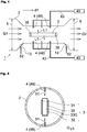
- a gas treatment device 1 shown in Fig. 1 includes a housing 2, an excimer lamp 3 housed inside the housing 2, and a cleaning mechanism 4.
- the excimer lamp 3 extends along a direction d1 (corresponding to a "first direction") in shape.
- Fig. 2 is a schematic plan view showing the excimer lamp 3 together with the cleaning mechanism 4, viewed along the direction d1.
- the excimer lamp 3 includes a tube body 30 extending along the direction d1, a first electrode 31 disposed on an outer surface of the tube body 30, and a second electrode 32 that is disposed on an outer surface of the tube body 30 and at a place opposite to the first electrode 31.
- the tube body 30 is made of a dielectric substance such as synthetic fused silica.
- An interior of the tube body 30 is filled with a discharge gas 33G that forms excimer molecules by electrical discharging.
- the discharge gas 33G contains xenon (Xe).
- the discharge gas 33G is a gas that contains both xenon (Xe) and neon (Ne) in a predetermined ratio (e.g., 3:7) and may further contain oxygen and hydrogen in minute quantities.
- An alternating-current voltage at a high frequency for example, approximately from 50 kHz to 5 MHz is applied between the first electrode 31 and the second electrode 32, and the voltage is thereby applied to the discharge gas 33G via the tube body 30 to produce discharge plasma in a discharge space filled with the discharge gas 33G.
- atoms in the discharge gas 33G are excited and get into an excimer state.
- excimer light is generated.
- the discharge gas 33G is the gas that contains xenon (Xe) described above
- the excimer light is ultraviolet light L1 having a wavelength close to 172 nm.
- the discharge gas 33G may contain a different substance to change the wavelength of the ultraviolet light L1.
- the discharge gas 33G may be a gas that contains a substance such as ArBr (165 nm), ArCI (175 nm), or F2 (153 nm).
- the first electrode 31 and the second electrode 32 each have a mesh shape (a net shape) or a linear shape so as not to hinder the ultraviolet light L1 generated inside the tube body 30 from being emitted to outside the tube body 30.
- the gas treatment device 1 is used to treat a gas to be treated G1 containing volatile organic compounds (VOC).
- VOC volatile organic compounds
- the VOC is a general term for organic compounds that have volatility and that are in gaseous form in the atmosphere, and is a general term for a group of substances including formaldehyde, toluene, xylene, acetone, and the like. It is assumed that the gas treatment device 1 is used, for example, by being directly connected with an air-conditioning duct in a building or an exhaust gas duct in a plant.
- the gas treatment device 1 has a gas inlet 5 to introduce the gas to be treated G1 containing the VOC into the housing 2 and a gas outlet 6 to exhaust a gas (a treated gas G2) to outside the housing 2 after the gas to be treated G1 is irradiated with the ultraviolet light L1 from the excimer lamp 3.
- the gas to be treated G1 containing the VOC and being suctioned from the gas inlet 5 is irradiated with the ultraviolet light L1 emitted from the excimer lamp 3 and thereby generates O( 1 D) and a hydroxy radical (•OH), which are highly reactive, through reactions shown in the following formulas (1) and (2).
- O( 1 D) represents an oxygen atom in an excited state
- O( 3 P) represents an oxygen atom in a ground state.
- h ⁇ ( ⁇ ) represents absorption of light at a wavelength ⁇ .
- the reaction shown in the above formula (1) is apt to occur when the wavelength ⁇ of the ultraviolet light L1 is less than or equal to 180 nm.
- the gas treatment device 1 can efficiently decompose the gas to be treated G1 containing a VOC-derived substance such as formaldehyde, which is hard to decompose by ozone.
- the gas treatment device 1 includes the cleaning mechanism 4.
- the cleaning mechanism 4 as shown in Fig. 2 , has a plurality of water injection pipes 48.
- Each of the water injection pipes 48 is, as shown in Fig. 1 , connected to a water supply source 40 through a water supply pipe 43.
- the water injection pipes 48 are formed so as to pass through some places of the housing 2 and are designed to spray water onto the tube body 30.
- the water is stored as a first fluid 51 in the water supply sources 40 disposed outside the housing 2.
- the water injection pipes 48 are formed only above and below the tube body 30 when viewed along the direction d1.
- the water injection pipes 48 may be disposed in any form.
- the water injection pipes 48 may be disposed at a plurality of places such that water as the first fluid 51 is allowed to be sprayed onto a surface of the tube body 30 in a plurality of directions.
- the above configuration allows the secondary product to be dissolved in the water supplied from the cleaning mechanism 4 (the water injection pipes 48). This can clean the surface of the tube body 30 and prevent a decrease in illuminance of the ultraviolet light L1. This feature will be described later with reference to examples.
- the gas treatment device 1 includes a drainage outlet 13. Since the water (the first fluid 51) is sprayed onto the surface of the tube body 30, the VOC-derived secondary product deposited on the surface of the tube body 30 is dissolved in the water and as a result, a fluid (a second fluid 52) is produced.
- the drainage outlet 13 is used to drain the second fluid to outside the housing 2.
- the drainage outlet 13 may have any shape and may be disposed at any place, with the proviso that the drainage outlet is configured to drain the second fluid 52, which is produced inside the housing 2, to outside the housing 2.
- the excimer lamp 3 includes a base 35 at each end of the tube body 30 in the direction d1.
- the bases 35 are made of a ceramic material (an inorganic material) such as steatite, forsterite, sialon, or alumina and have a function of fixing the ends of the tube body 30.
- Power feeders (not shown) are placed through a hole formed in the bases 35 or along an outer edge of the bases 35 to supply electricity to the first electrode 31 and the second electrode 32.
- the base 35 absorbs moisture, the absorbed moisture creates a risk of a short circuit between the power feeders placed in close vicinity of the base 35.
- the cleaning mechanism 4 be configured not to spray water onto the bases 35 but to spray water onto the surface of the tube body 30 positioned inward from the bases 35.
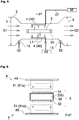
- Fig. 3 is a drawing showing, in like manner with Fig. 1 , a structure of a gas treatment device 1 according to another embodiment.
- the gas treatment device of this embodiment differs from the gas treatment device 1 shown in Fig. 1 in configuration of a cleaning mechanism 4.
- Fig. 4 is a schematic plan view showing the excimer lamp 3 together with the cleaning mechanism 4, viewed along the direction d1.
- the cleaning mechanism 4 as shown in Fig. 4 , includes a nozzle member 41 that has a ring shape and that is disposed so as to substantially surround an outer periphery of the tube body 30 of the excimer lamp 3.
- the nozzle member 41 has a plurality of holes 42 facing in directions to the tube body 30.
- Substantially surrounding the outer periphery of the tube body 30 of the excimer lamp 3 includes a meaning of surrounding a 50% or greater extent of the outer periphery of the tube body 30, as well as completely surrounding the outer periphery of the tube body 30.
- the nozzle member 41 may have an annular shape that lacks a part, such as a C shape or a U shape, as well as a fully annular shape.
- the cleaning mechanism 4 is allowed to move along the tube body 30 in the direction d1.
- Fig. 3 also shows the cleaning mechanism 4 indicated by a dashed line and thereby shows that the cleaning mechanism 4 is allowed to move.
- This configuration allows the cleaning mechanism 4 to spray water as the first fluid 51 over a wide area of the surface of the tube body 30 in the direction d1 and clean the wide area of the surface of the tube body 30.
- the cleaning mechanism 4 may be moved manually or may be allowed to move via a drive mechanism (not shown) such as a motor.
- a rail designed to move the cleaning mechanism 4 along the direction d1 may be placed inside the housing 2, for example, to allow an operator outside the housing 2 to move the cleaning mechanism 4 along the rail.
- the gas treatment device 1 having the configuration shown in Figs. 3 and 4 , when a secondary product derived from the VOC is deposited on the surface of the tube body 30, also allows the secondary product to be dissolved in the water acting as the first fluid 51. This can clean the surface of the tube body 30 and prevent a decrease in illuminance of the ultraviolet light L1.
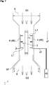
- Fig. 5 is a drawing showing, in like manner with Fig. 1 , a structure of a gas treatment device 1 according to still another embodiment.
- the gas treatment device of this embodiment differs from the gas treatment device 1 shown in Fig. 1 in configuration of a cleaning mechanism 4.
- Fig. 6 is a schematic plan view showing the excimer lamp 3 together with the cleaning mechanism 4, viewed along the direction d1.
- the cleaning mechanism 4, as shown in Fig. 6 includes an air knife 46 to spray humidified air 51a as a first fluid 51 onto the surface of the tube body 30 of the excimer lamp 3.
- the air knife 46 is supplied with the humidified air 51a as the first fluid 51 from a humidified air source 45 through an air supply pipe 47 and is allowed to splay the humidified air 51a (the first fluid 51) onto the tube body 30.
- the humidified air 51a is preferably air with 85% or higher relative humidity and is more preferably air with 95% or higher relative humidity.
- Fig. 6 shows an instance in which the humidified air 51a ejected as the first fluid 51 from the air knife 46 has a sheet shape, and the sheet-shaped air has an end parallel to a direction of a width of the tube body 30 (a lateral direction of the figure) when viewed along the direction d1.
- the air knife 46 for example, ejects the sheet-shaped humidified air 51a from a plurality of places that are separated from each other in the direction d1.
- the sheet-shaped humidified air 51a may have any shape, and a distal end of the sheet-shaped humidified air 51a may have, for example, a planar shape extending along the direction d1.
- the air knife 46 may eject the sheet-shaped humidified air 51a acting as the first fluid 51 onto surfaces where the electrodes (31, 32) are not formed, in addition to surfaces where the electrodes (31, 32) are formed, out of outer surfaces of the tube body 30.
- the gas treatment device 1 having the configuration shown in Figs. 5 and 6 , when a secondary product derived from the VOC is deposited on the surface of the tube body 30, also allows the secondary product to be dissolved in moisture contained in the humidified air 51a. This can clean the surface of the tube body 30 and prevent a decrease in illuminance of the ultraviolet light L1.
- the gas treatment device 1 is configured to eject the humidified air 51a from the air knife 46 and thereby allows the secondary product to readily come off the surface of the tube body 30 by wind force at the distal end of the sheet-shaped humidified air 51a while allowing the secondary product to be dissolved in the contained moisture.
- the inventor treated the gas to be treated G1 using the excimer lamp 3 and found a phenomenon in which dirt (a contaminant) gets deposited on the surface of the tube body 30 of the excimer lamp 3.
- the inventor checked that letting the gas to be treated G1 flow through inside the housing 2 with the excimer lamp 3 unlit was not enough to cause a contaminant to be deposited on the surface of the tube body 30.
- the inventor presumed that irradiating the gas to be treated G1 with the ultraviolet light L1 emitted from the excimer lamp 3 causes generation of a secondary product and the generated secondary product gets deposited on the surface of the tube body 30.
- the excimer lamp 3 was lit at 26.4 W, input power of a power source for lighting, and the illuminance at a middle place A of the surface of the tube body 30 in the direction d1 was measured with an illuminometer.
- the measured illuminance was 30.0 mW/cm 2 .
- Example 2 After dry air (10% relative humidity) (Comparative Example 2), water (Example 1), humidified air (85% relative humidity) (Example 2), and humidified air (95% relative humidity) (Example 3) were each sprayed onto the excimer lamp 3 in a situation of Comparative Example 1 for 60 seconds, the illuminances at the place A were measured with the illuminometer. In Example 1, the illuminance at the place A was measured with the illuminometer after drops of the water were removed by blowing ordinary air for 30 seconds following spraying of the water to avoid a state in which the drops of the water remained attached to the surface of the tube body 30. Results yielded in the examples are as shown below in Table 1.
- Example 2 In all of Comparative Example 2, Example 2, and Example 3, a flow rate of the air was 37 L/min. In Example 1, the water was supplied at a flow rate of 0.5 L/min.
- Example 1 Illuminance [mW/cm 2 ] Before treatment of gas to be treated 30.0 After treatment of gas to be treated Comparative Example 1 (before spraying fluid) 0.0 Comparative Example 2 (dry air) 0.0 Example 1 (water) 28.2
- Example 2 humidity: 85% relative humidity) 26.1
- Example 3 humidity: 95% relative humidity
- Comparative Example 2 verifies that even when the dry air was sprayed on the surface of the tube body 30, the illuminance remained unchanged from the condition in Comparative Example 1 and the sprayed air failed to cause the contaminant to come off the surface of the tube body 30.
- the illuminance increased from that in Comparative Example 1 and degree of decline from the illuminance before introduction of the gas to be treated G1 into the housing 2 was very small compared to that in Comparative Examples 1 to 2. This proves that spraying water or humidified air onto the surface of the tube body 30 allows the contaminant to be dissolved in the water and come off the surface of the tube body 30.
- the gas to be treated G1 that is a gas containing xylene as VOC was introduced into the housing 2, the gas to be treated G1 was treated with the excimer lamp 3 lit.
- the inventor analyzed a secondary product deposited on the tube body 30 of the excimer lamp 3 and verified that 2,5/2,6-xylenol, 2,5/2,6-dimethyl hydroquinone, and 4,5-dimethylresorcinol were contained. All these are substances containing hydroxy groups.
- the gas treatment device 1 may be disposed in any direction.
- the gas treatment device 1 may be disposed in the direction d1 specified as a vertical direction.
- the fluid (the second fluid 52), which is produced when the VOC-derived secondary product deposited on the surface of the tube body 30 is dissolved in the water, moves in the housing 2 downward by gravity.
- the gas treatment device 1 may not necessarily include the drainage outlet 13.
- the gas treatment device 1 may include a reservoir (not shown) to temporarily store the second fluid 52, which runs along an inner wall surface of the housing 2 and flows to outside the housing 2 from the gas outlet 6.
- the excimer lamp 3 may have any structure.
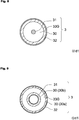
- the excimer lamp 3 may have what is called a "single-tube structure", or as shown in Fig. 9 , the excimer lamp 3 may have what is called a "double-tube structure”.
- Figs. 8 and 9 are schematic views each showing a structure of the excimer lamp 3, viewed along the direction d1.
- the excimer lamp 3 shown in Fig. 8 includes the first electrode 31 disposed inside the tube body 30, the discharge gas 33G filling the interior of the tube body 30, and the second electrode 32 disposed on an outer wall surface of the tube body 30.
- the first electrode 31 extends along the direction d1 in shape and the second electrode 32 has a mesh shape or a linear shape.
- the excimer lamp 3 shown in Fig. 9 has two tube bodies 30 (30a, 30b).
- the excimer lamp includes the tube body 30b, which is cylindrical and is disposed on an external side, and the tube body 30a, which is cylindrical and is disposed inside the tube body 30b so as to be coaxial with the tube body 30b.
- An inner diameter of the tube body 30a is smaller than that of the tube body 30b.
- the tube body 30a and the tube body 30b are sealed off at each end (not shown) in the direction d1.
- An annular light-emission space is formed between the two tube bodies. The space is filled with the discharge gas 33G.
- the first electrode 31 is disposed on an inner wall surface of the inside tube body 30a, and the second electrode 32 is disposed on an outer wall surface of the outside tube body 30b.
- the first electrode 31 has a layer shape, and the second electrode 32 has a mesh shape or a linear shape.
- the configurations of the cleaning mechanism 4 in the embodiments described above are merely examples.
- the cleaning mechanism 4 included in the gas treatment device 1 of the present invention is not limited to the illustrated forms. In other words, the cleaning mechanism 4 may have any configuration with the proviso that the cleaning mechanism is allowed to spray the first fluid 51 containing moisture from an inside of the housing 2 onto the surface of the tube body 30.
- the cleaning mechanism 4 may be detachable from the gas treatment device 1.
- the first fluid 51 is either of water or humidified air.
- the first fluid 51 is not necessarily pure water.
- the first fluid 51 may be water containing a surface-active agent. This enhances the effect of causing the secondary product deposited on the surface of the tube body 30 to come off.
- the first fluid 51 may be water containing any of other substances except VOC, as well as the surface-active agent.
- the first fluid 51 when the first fluid 51 is water or water containing any of the other substances, the first fluid may not be a pure liquid but may be made up of a mist of drops with a particle diameter ranging approximately from several micrometers to several tens of micrometers or a mixture of the mist and air.
- the first fluid 51 conceptually includes a case in which a fluid is in the form of minute particles floating in a gas (or being atomized).
- the first fluid 51 is not necessarily a gas of pure air that is humidified.
- the first fluid may be a gas of humidified air containing any of other substances except VOC-derived substances.
Landscapes
- Chemical & Material Sciences (AREA)
- Engineering & Computer Science (AREA)
- Health & Medical Sciences (AREA)
- Environmental & Geological Engineering (AREA)
- Chemical Kinetics & Catalysis (AREA)
- Oil, Petroleum & Natural Gas (AREA)
- General Chemical & Material Sciences (AREA)
- Analytical Chemistry (AREA)
- Biomedical Technology (AREA)
- Animal Behavior & Ethology (AREA)
- Life Sciences & Earth Sciences (AREA)
- Dispersion Chemistry (AREA)
- General Health & Medical Sciences (AREA)
- Veterinary Medicine (AREA)
- Public Health (AREA)
- Epidemiology (AREA)
- Physical Or Chemical Processes And Apparatus (AREA)
- Disinfection, Sterilisation Or Deodorisation Of Air (AREA)
- Gas Separation By Absorption (AREA)
- Cleaning By Liquid Or Steam (AREA)
Abstract
Description
- The present invention relates to a gas treatment device. In particular, the invention relates to a device for treating a gas to be treated using an excimer lamp.
- Conventionally, techniques have been presented to purify gases to be treated using low-pressure mercury lamps. For instance,
Patent Document 1 described below discloses that a low-pressure mercury lamp that emits ultraviolet light having a wavelength of 185 nm or a wavelength of 254 nm is used to decompose and remove impurities and bacteria contained in a gas to be treated. Specifically, a description is given of a technique for generating an ozone (03) gas by ultraviolet light having a wavelength of 185 nm and decomposing impurities and a malodorous substance by the ozone gas. -
Patent Document 2 described below discloses a xenon excimer lamp designed to emit light at 172 nm, which is a wavelength shorter than the wavelengths of the above low-pressure mercury lamp. -
- Patent Document 1:
JP-A-2006-204683 - Patent Document 2:
JP-A-2007-335350 - Conventional excimer lamps, as is disclosed in
Patent Document 2, have been used to remove organic substances in manufacturing processes for semiconductors or liquid crystal panels. In other words, excimer lamps have been normally used in a clean environment that is precisely controlled. - The inventor has been examining a way of increasing efficiency in decomposition of volatile organic compounds (VOC) and improving sterilization performance by using this excimer lamp instead of the low-pressure mercury lamp as is described in
Patent Document 1 and irradiating a gas to be treated with light having a shortened wavelength. In particular, when the gas to be treated contains oxygen and moisture and the gas is irradiated with short-wavelength light emitted from the excimer lamp, O(1D) and a hydroxy radical (•OH), which are highly reactive, are generated. Thus, high performance in decomposition of VOC contained in the gas to be treated is anticipated. - The inventor has extensively studied on treatment of a VOC-containing gas to be treated using an excimer lamp and found a new problem of this technique. As the treatment continues, a contaminant gets deposited on a surface of a tube body of the excimer lamp and an illuminance of ultraviolet light emitted from the excimer lamp decreases. An occurrence of such a situation results in a decrease in capacity for treatment of VOC over time and thus is unfavorable.
- The inventor conducted an experiment that involved putting off an excimer lamp and letting a VOC-containing gas to be treated pass through an immediate vicinity of the unlit excimer lamp. As a result, even after a lapse of time, contamination was not identified on a tube body of the excimer lamp. Based on this result, the inventor has presumed that irradiating a VOC-containing gas to be treated with ultraviolet light emitted from an excimer lamp that is lit causes generation of the contaminant and deposition of the contaminant on the tube body.
- It is an object of the present invention to provide a gas treatment device that can prevent a decrease in capacity for treatment of a VOC-containing gas to be treated over time.
- A gas treatment device according to an aspect of the present invention includes:
- a housing;
- a gas inlet to introduce a gas to be treated containing volatile organic compounds (VOC) into the housing;
- an excimer lamp housed inside the housing, the excimer lamp including a tube body with a long shape extending in a first direction, an interior of the tube body being filled with a discharge gas;
- a gas outlet to exhaust the gas to be treated to outside the housing, the gas to be treated being irradiated with ultraviolet light emitted from the excimer lamp; and
- a cleaning mechanism to spray a first fluid from an inside of the housing onto a surface of the tube body, the first fluid containing moisture and being used for cleaning.
- Owing to the extensive study on treatment of the VOC-containing gas to be treated using the lit excimer lamp, the inventor has found that the contaminant deposited on the surface of the tube body of the excimer lamp as a result of continuation of the treatment can be dissolved in a fluid containing moisture and come off the surface of the tube body. It can be inferred that the contaminant is a substance derived from VOC and is a secondary product generated by being irradiated with ultraviolet light. According to the configuration, the gas treatment device includes the cleaning mechanism to spray the first fluid containing moisture. Thus, even if a contaminant gets deposited on the surface of the tube body, the gas treatment device allows the contaminant to come off the surface of the tube body by spraying the first fluid onto the surface of the tube body. This can prevent a decrease in illuminance of the ultraviolet light over time.
- The excimer lamp may include a base made of an inorganic material at an end of the tube body in the first direction, and the cleaning mechanism may spray the fluid for cleaning onto the surface of the tube body positioned inward from the base.
- The base is a member having a function of supporting the end of the tube body and is made of, for example, a ceramic material such as steatite, forsterite, sialon, or alumina. Power feeders are placed through a hole formed in the base or along an outer edge of the base to supply a voltage to the excimer lamp. Thus, if a fluid containing moisture is sprayed onto the base and the base absorbs the moisture, the absorbed moisture creates a risk of a short circuit between the power feeders placed through the base. According to the above configuration, the cleaning mechanism sprays the first fluid onto the surface of the tube body positioned inward from the base. This reduces the risk that the moisture is absorbed by the base when a cleaning process is performed.
- The housing may include a drainage outlet to drain a second fluid in liquid form to outside the housing. The second fluid is left after the surface of the tube body is cleaned with the first fluid.
- This configuration allows the second fluid, which is produced when the VOC-derived secondary product is dissolved in the moisture, to be drained to outside the housing through the drainage outlet. This reduces the occurrence of a problem of accumulation of the second fluid inside the housing.
- The cleaning mechanism may include:
- a water injection pipe disposed so as to pass through a part of the housing; and
- a water supply pipe disposed outside the housing to supply water as the first fluid to the water injection pipe, and
- the water injection pipe may spray the water as the first fluid onto the surface of the tube body.
- The cleaning mechanism may allow a target onto which the first fluid is sprayed to be shifted along the first direction.
- According to this configuration, a contaminant deposited over a wide area of the surface of the tube body of the excimer lamp can come off.
- The cleaning mechanism may include:
- a nozzle member that has a ring shape so as to substantially surround an outer periphery of the surface of the tube body and that has a plurality of holes in a surface facing the tube body; and
- a water supply pipe to supply water as the first fluid to the nozzle member.
- According to this configuration, a contaminant deposited circumferentially over a wide area of the surface of the tube body can come off.
- The cleaning mechanism may include an air knife to spray humidified air as the first fluid in planar form.
- According to this configuration, a distal end of the air knife is directed at the surface of the tube body. This allows the contaminant to readily come off the surface of the tube body by a wind current from the air knife while allowing the contaminant to be dissolved in the moisture.
- The excimer lamp included in the gas treatment device may have any shape.
- In one example, the excimer lamp may include a first electrode disposed at a predetermined place on an outer surface of the tube body and a second electrode that is disposed on an outer surface of the tube body and at a place opposite to the first electrode through the interior of the tube body filled with the discharge gas. In this case, the tube body may have two faces that are substantially flat in shape and opposite to each other, and the first electrode may be disposed on one of the faces and the second electrode may be disposed on the other face.
- In another example, the excimer lamp may include a first electrode disposed at a predetermined place on an outer surface of the tube body and a second electrode disposed in the interior of the tube body filled with the discharge gas.
- In still another example, the excimer lamp may have a double-tube structure such that the tube body includes an outside tube and an inside tube disposed inside the outside tube and such that the outside tube and the inside tube are sealed off at both ends of the tube body in the first direction,
- a space between the inside tube and the outside tube may be filled with the discharge gas, and
- the excimer lamp may include a first electrode disposed on an outer surface of the outside tube and a second electrode disposed on an inner surface of the inside tube.
- A gas treatment device according to the present invention can prevent a decrease in capacity for treatment of a VOC-containing gas to be treated over time.
-
-
Fig. 1 is a schematic cross-sectional view showing a configuration of a gas treatment device according to an embodiment of the present invention. -
Fig. 2 is a schematic plan view showing an excimer lamp included in the gas treatment device ofFig. 1 together with a cleaning mechanism, viewed along a direction d1. -
Fig. 3 is a schematic cross-sectional view showing a configuration of a gas treatment device according to an embodiment of the present invention. -
Fig. 4 is a schematic plan view showing an excimer lamp included in the gas treatment device ofFig. 3 together with a cleaning mechanism, viewed along a direction d1. -
Fig. 5 is a schematic cross-sectional view showing a configuration of a gas treatment device according to another embodiment of the present invention. -
Fig. 6 is a schematic plan view showing an excimer lamp included in the gas treatment device ofFig. 5 together with a cleaning mechanism, viewed along a direction d1. -
Fig. 7 is a schematic cross-sectional view showing a configuration of a gas treatment device according to another embodiment of the present invention. -
Fig. 8 is a schematic plan view of an excimer lamp that has another example configuration and that is included in a gas treatment device of the present invention, viewed along a direction d1. -
Fig. 9 is a schematic plan view of an excimer lamp that has still another example configuration and that is included in a gas treatment device of the present invention, viewed along a direction d1. - Gas treatment devices according to embodiments of the present invention will be described with reference to the drawings as appropriate. All the drawings shown below are schematic views, and dimensions or proportions in the drawings do not always coincide with actual dimensions or proportions. Dimensions or proportions do not always coincide between the drawings.
-
Fig. 1 is a schematic cross-sectional view showing a configuration of a gas treatment device according to an embodiment. Agas treatment device 1 shown inFig. 1 includes ahousing 2, anexcimer lamp 3 housed inside thehousing 2, and acleaning mechanism 4. - The
excimer lamp 3 extends along a direction d1 (corresponding to a "first direction") in shape.Fig. 2 is a schematic plan view showing theexcimer lamp 3 together with thecleaning mechanism 4, viewed along the direction d1. In the present embodiment, theexcimer lamp 3 includes atube body 30 extending along the direction d1, afirst electrode 31 disposed on an outer surface of thetube body 30, and asecond electrode 32 that is disposed on an outer surface of thetube body 30 and at a place opposite to thefirst electrode 31. Thetube body 30 is made of a dielectric substance such as synthetic fused silica. An interior of thetube body 30 is filled with adischarge gas 33G that forms excimer molecules by electrical discharging. In the present embodiment, thedischarge gas 33G contains xenon (Xe). In one specific example, thedischarge gas 33G is a gas that contains both xenon (Xe) and neon (Ne) in a predetermined ratio (e.g., 3:7) and may further contain oxygen and hydrogen in minute quantities. - An alternating-current voltage at a high frequency, for example, approximately from 50 kHz to 5 MHz is applied between the
first electrode 31 and thesecond electrode 32, and the voltage is thereby applied to thedischarge gas 33G via thetube body 30 to produce discharge plasma in a discharge space filled with thedischarge gas 33G. As a result, atoms in thedischarge gas 33G are excited and get into an excimer state. When the atoms transition to a ground state, excimer light is generated. When thedischarge gas 33G is the gas that contains xenon (Xe) described above, the excimer light is ultraviolet light L1 having a wavelength close to 172 nm. Thedischarge gas 33G may contain a different substance to change the wavelength of the ultraviolet light L1. For instance, thedischarge gas 33G may be a gas that contains a substance such as ArBr (165 nm), ArCI (175 nm), or F2 (153 nm). - The
first electrode 31 and thesecond electrode 32 each have a mesh shape (a net shape) or a linear shape so as not to hinder the ultraviolet light L1 generated inside thetube body 30 from being emitted to outside thetube body 30. - The
gas treatment device 1 is used to treat a gas to be treated G1 containing volatile organic compounds (VOC). The VOC is a general term for organic compounds that have volatility and that are in gaseous form in the atmosphere, and is a general term for a group of substances including formaldehyde, toluene, xylene, acetone, and the like. It is assumed that thegas treatment device 1 is used, for example, by being directly connected with an air-conditioning duct in a building or an exhaust gas duct in a plant. - As shown in
Fig. 1 , thegas treatment device 1 has agas inlet 5 to introduce the gas to be treated G1 containing the VOC into thehousing 2 and agas outlet 6 to exhaust a gas (a treated gas G2) to outside thehousing 2 after the gas to be treated G1 is irradiated with the ultraviolet light L1 from theexcimer lamp 3. - The gas to be treated G1 containing the VOC and being suctioned from the
gas inlet 5 is irradiated with the ultraviolet light L1 emitted from theexcimer lamp 3 and thereby generates O(1D) and a hydroxy radical (•OH), which are highly reactive, through reactions shown in the following formulas (1) and (2). In the following formulas, O(1D) represents an oxygen atom in an excited state, and O(3P) represents an oxygen atom in a ground state. In addition, hν(λ) represents absorption of light at a wavelength λ.
O2 + hν(λ) → O(1D) + O(3P) ... (1)
O(1D) + H2O → •OH + •OH ... (2)
- The reaction shown in the above formula (1) is apt to occur when the wavelength λ of the ultraviolet light L1 is less than or equal to 180 nm.
- The reactivity of O(1D) and the hydroxy radical (•OH) is higher than that of ozone (O3). Thus, as compared to the conventional gas treatment device designed to decompose a gas by ozone generated using the low-pressure mercury lamp, the
gas treatment device 1 can efficiently decompose the gas to be treated G1 containing a VOC-derived substance such as formaldehyde, which is hard to decompose by ozone. - The
gas treatment device 1 includes thecleaning mechanism 4. In the present embodiment, thecleaning mechanism 4, as shown inFig. 2 , has a plurality ofwater injection pipes 48. Each of thewater injection pipes 48 is, as shown inFig. 1 , connected to awater supply source 40 through awater supply pipe 43. Thewater injection pipes 48 are formed so as to pass through some places of thehousing 2 and are designed to spray water onto thetube body 30. The water is stored as afirst fluid 51 in thewater supply sources 40 disposed outside thehousing 2. - In illustrations of
Figs. 1 and 2 , thewater injection pipes 48 are formed only above and below thetube body 30 when viewed along the direction d1. However, thewater injection pipes 48 may be disposed in any form. In other words, thewater injection pipes 48 may be disposed at a plurality of places such that water as thefirst fluid 51 is allowed to be sprayed onto a surface of thetube body 30 in a plurality of directions. - Even if a secondary product derived from the VOC is deposited on the surface of the
tube body 30, the above configuration allows the secondary product to be dissolved in the water supplied from the cleaning mechanism 4 (the water injection pipes 48). This can clean the surface of thetube body 30 and prevent a decrease in illuminance of the ultraviolet light L1. This feature will be described later with reference to examples. - In the present embodiment, the
gas treatment device 1 includes adrainage outlet 13. Since the water (the first fluid 51) is sprayed onto the surface of thetube body 30, the VOC-derived secondary product deposited on the surface of thetube body 30 is dissolved in the water and as a result, a fluid (a second fluid 52) is produced. Thedrainage outlet 13 is used to drain the second fluid to outside thehousing 2. Thedrainage outlet 13 may have any shape and may be disposed at any place, with the proviso that the drainage outlet is configured to drain thesecond fluid 52, which is produced inside thehousing 2, to outside thehousing 2. - The
excimer lamp 3 includes a base 35 at each end of thetube body 30 in the direction d1. Thebases 35 are made of a ceramic material (an inorganic material) such as steatite, forsterite, sialon, or alumina and have a function of fixing the ends of thetube body 30. - Power feeders (not shown) are placed through a hole formed in the
bases 35 or along an outer edge of thebases 35 to supply electricity to thefirst electrode 31 and thesecond electrode 32. Thus, if thebase 35 absorbs moisture, the absorbed moisture creates a risk of a short circuit between the power feeders placed in close vicinity of thebase 35. In view of avoiding such a short-circuit fault, it is preferred that thecleaning mechanism 4 be configured not to spray water onto thebases 35 but to spray water onto the surface of thetube body 30 positioned inward from thebases 35. -
Fig. 3 is a drawing showing, in like manner withFig. 1 , a structure of agas treatment device 1 according to another embodiment. The gas treatment device of this embodiment differs from thegas treatment device 1 shown inFig. 1 in configuration of acleaning mechanism 4.Fig. 4 is a schematic plan view showing theexcimer lamp 3 together with thecleaning mechanism 4, viewed along the direction d1. - In the present embodiment, the
cleaning mechanism 4, as shown inFig. 4 , includes anozzle member 41 that has a ring shape and that is disposed so as to substantially surround an outer periphery of thetube body 30 of theexcimer lamp 3. Thenozzle member 41 has a plurality ofholes 42 facing in directions to thetube body 30. - "Substantially surrounding the outer periphery of the
tube body 30 of theexcimer lamp 3" includes a meaning of surrounding a 50% or greater extent of the outer periphery of thetube body 30, as well as completely surrounding the outer periphery of thetube body 30. In other words, thenozzle member 41 may have an annular shape that lacks a part, such as a C shape or a U shape, as well as a fully annular shape. - Preferably, the
cleaning mechanism 4 is allowed to move along thetube body 30 in the direction d1.Fig. 3 also shows thecleaning mechanism 4 indicated by a dashed line and thereby shows that thecleaning mechanism 4 is allowed to move. This configuration allows thecleaning mechanism 4 to spray water as thefirst fluid 51 over a wide area of the surface of thetube body 30 in the direction d1 and clean the wide area of the surface of thetube body 30. In this case, thecleaning mechanism 4 may be moved manually or may be allowed to move via a drive mechanism (not shown) such as a motor. In the former, a rail designed to move thecleaning mechanism 4 along the direction d1 may be placed inside thehousing 2, for example, to allow an operator outside thehousing 2 to move thecleaning mechanism 4 along the rail. - The
gas treatment device 1 having the configuration shown inFigs. 3 and 4 , when a secondary product derived from the VOC is deposited on the surface of thetube body 30, also allows the secondary product to be dissolved in the water acting as thefirst fluid 51. This can clean the surface of thetube body 30 and prevent a decrease in illuminance of the ultraviolet light L1. -
Fig. 5 is a drawing showing, in like manner withFig. 1 , a structure of agas treatment device 1 according to still another embodiment. The gas treatment device of this embodiment differs from thegas treatment device 1 shown inFig. 1 in configuration of acleaning mechanism 4.Fig. 6 is a schematic plan view showing theexcimer lamp 3 together with thecleaning mechanism 4, viewed along the direction d1. In the present embodiment, thecleaning mechanism 4, as shown inFig. 6 , includes anair knife 46 to spray humidifiedair 51a as afirst fluid 51 onto the surface of thetube body 30 of theexcimer lamp 3. - As shown in
Fig. 5 , theair knife 46 is supplied with the humidifiedair 51a as the first fluid 51 from a humidifiedair source 45 through anair supply pipe 47 and is allowed to splay the humidifiedair 51a (the first fluid 51) onto thetube body 30. The humidifiedair 51a is preferably air with 85% or higher relative humidity and is more preferably air with 95% or higher relative humidity. -
Fig. 6 shows an instance in which the humidifiedair 51a ejected as the first fluid 51 from theair knife 46 has a sheet shape, and the sheet-shaped air has an end parallel to a direction of a width of the tube body 30 (a lateral direction of the figure) when viewed along the direction d1. In other words, the present embodiment assumes that theair knife 46, for example, ejects the sheet-shaped humidifiedair 51a from a plurality of places that are separated from each other in the direction d1. However, the sheet-shaped humidifiedair 51a may have any shape, and a distal end of the sheet-shaped humidifiedair 51a may have, for example, a planar shape extending along the direction d1. Theair knife 46 may eject the sheet-shaped humidifiedair 51a acting as thefirst fluid 51 onto surfaces where the electrodes (31, 32) are not formed, in addition to surfaces where the electrodes (31, 32) are formed, out of outer surfaces of thetube body 30. - The
gas treatment device 1 having the configuration shown inFigs. 5 and 6 , when a secondary product derived from the VOC is deposited on the surface of thetube body 30, also allows the secondary product to be dissolved in moisture contained in the humidifiedair 51a. This can clean the surface of thetube body 30 and prevent a decrease in illuminance of the ultraviolet light L1. Thegas treatment device 1 is configured to eject the humidifiedair 51a from theair knife 46 and thereby allows the secondary product to readily come off the surface of thetube body 30 by wind force at the distal end of the sheet-shaped humidifiedair 51a while allowing the secondary product to be dissolved in the contained moisture. - As described above in the 'PROBLEMS TO BE SOLVED BY THE INVENTION' section, the inventor treated the gas to be treated G1 using the
excimer lamp 3 and found a phenomenon in which dirt (a contaminant) gets deposited on the surface of thetube body 30 of theexcimer lamp 3. The inventor checked that letting the gas to be treated G1 flow through inside thehousing 2 with theexcimer lamp 3 unlit was not enough to cause a contaminant to be deposited on the surface of thetube body 30. Based on the result of this experiment, the inventor presumed that irradiating the gas to be treated G1 with the ultraviolet light L1 emitted from theexcimer lamp 3 causes generation of a secondary product and the generated secondary product gets deposited on the surface of thetube body 30. - The inventor presumed that when the gas to be treated G1 containing VOC is irradiated with the ultraviolet light L1 and the VOC is decomposed, a hydroxy group is added and thereby the secondary product apt to be dissolved in water is generated. Thus, the inventor presumed that by causing the
cleaning mechanism 4 to spray the first fluid 51 (water, humidified air, or the like) onto the surface of thetube body 30 of theexcimer lamp 3 on which the contaminant is deposited, the secondary product could be dissolved and come off thetube body 30, and the inventor conducted an experiment. An outcome of the experiment is described below. - Before the gas to be treated G1 was introduced into the
housing 2, theexcimer lamp 3 was lit at 26.4 W, input power of a power source for lighting, and the illuminance at a middle place A of the surface of thetube body 30 in the direction d1 was measured with an illuminometer. The measured illuminance was 30.0 mW/cm2. - Next, while the gas to be treated G1 was introduced into the
housing 2, the gas to be treated G1 was treated for 300 hours with theexcimer lamp 3 lit. Subsequently, the illuminance at the place A was measured with the illuminometer. The measured illuminance was 0.0 mW/cm2 (Comparative Example 1). Based on the result of Comparative Example 1, it is inferred that the surface of thetube body 30 of theexcimer lamp 3 was covered with a contaminant. - After dry air (10% relative humidity) (Comparative Example 2), water (Example 1), humidified air (85% relative humidity) (Example 2), and humidified air (95% relative humidity) (Example 3) were each sprayed onto the
excimer lamp 3 in a situation of Comparative Example 1 for 60 seconds, the illuminances at the place A were measured with the illuminometer. In Example 1, the illuminance at the place A was measured with the illuminometer after drops of the water were removed by blowing ordinary air for 30 seconds following spraying of the water to avoid a state in which the drops of the water remained attached to the surface of thetube body 30. Results yielded in the examples are as shown below in Table 1. In all of Comparative Example 2, Example 2, and Example 3, a flow rate of the air was 37 L/min. In Example 1, the water was supplied at a flow rate of 0.5 L/min.[Table 1] Illuminance [mW/cm2] Before treatment of gas to be treated 30.0 After treatment of gas to be treated Comparative Example 1 (before spraying fluid) 0.0 Comparative Example 2 (dry air) 0.0 Example 1 (water) 28.2 Example 2 (humidified air: 85% relative humidity) 26.1 Example 3 (humidified air: 95% relative humidity) 26.5 - Comparative Example 2 verifies that even when the dry air was sprayed on the surface of the
tube body 30, the illuminance remained unchanged from the condition in Comparative Example 1 and the sprayed air failed to cause the contaminant to come off the surface of thetube body 30. In contrast, in any of Examples 1 to 3, the illuminance increased from that in Comparative Example 1 and degree of decline from the illuminance before introduction of the gas to be treated G1 into thehousing 2 was very small compared to that in Comparative Examples 1 to 2. This proves that spraying water or humidified air onto the surface of thetube body 30 allows the contaminant to be dissolved in the water and come off the surface of thetube body 30. - It is deduced that a reason why the method in Comparative Example 2 failed to cause the contaminant to come off the surface of the
tube body 30 is, after the VOC-derived secondary product turns into aerosols and comes into contact with the surface of thetube body 30, the aerosols are polymerized and the contaminant thereby having viscosity gets deposited firmly on the surface of thetube body 30. Meanwhile, in a course of decomposition of the VOC, a reaction by which a hydroxy group is added occurs. Presumably, the secondary product contains the hydroxy group and hence contains a substance apt to be dissolved in water. Actually, while the gas to be treated G1 that is a gas containing xylene as VOC was introduced into thehousing 2, the gas to be treated G1 was treated with theexcimer lamp 3 lit. The inventor analyzed a secondary product deposited on thetube body 30 of theexcimer lamp 3 and verified that 2,5/2,6-xylenol, 2,5/2,6-dimethyl hydroquinone, and 4,5-dimethylresorcinol were contained. All these are substances containing hydroxy groups. - <1 > The
gas treatment device 1 may be disposed in any direction. In one example, as shown inFig. 7 , thegas treatment device 1 may be disposed in the direction d1 specified as a vertical direction. In this case, the fluid (the second fluid 52), which is produced when the VOC-derived secondary product deposited on the surface of thetube body 30 is dissolved in the water, moves in thehousing 2 downward by gravity. Thus, as shown inFig. 7 , thegas treatment device 1 may not necessarily include thedrainage outlet 13. In a configuration shown inFig. 7 , thegas treatment device 1 may include a reservoir (not shown) to temporarily store thesecond fluid 52, which runs along an inner wall surface of thehousing 2 and flows to outside thehousing 2 from thegas outlet 6. - <2> In the present invention, the
excimer lamp 3 may have any structure. For instance, as shown inFig. 8 , theexcimer lamp 3 may have what is called a "single-tube structure", or as shown inFig. 9 , theexcimer lamp 3 may have what is called a "double-tube structure".Figs. 8 and 9 are schematic views each showing a structure of theexcimer lamp 3, viewed along the direction d1. - The
excimer lamp 3 shown inFig. 8 includes thefirst electrode 31 disposed inside thetube body 30, thedischarge gas 33G filling the interior of thetube body 30, and thesecond electrode 32 disposed on an outer wall surface of thetube body 30. In this case, thefirst electrode 31 extends along the direction d1 in shape and thesecond electrode 32 has a mesh shape or a linear shape. - The
excimer lamp 3 shown inFig. 9 has two tube bodies 30 (30a, 30b). The excimer lamp includes thetube body 30b, which is cylindrical and is disposed on an external side, and the tube body 30a, which is cylindrical and is disposed inside thetube body 30b so as to be coaxial with thetube body 30b. An inner diameter of the tube body 30a is smaller than that of thetube body 30b. The tube body 30a and thetube body 30b are sealed off at each end (not shown) in the direction d1. An annular light-emission space is formed between the two tube bodies. The space is filled with thedischarge gas 33G. Thefirst electrode 31 is disposed on an inner wall surface of the inside tube body 30a, and thesecond electrode 32 is disposed on an outer wall surface of theoutside tube body 30b. Thefirst electrode 31 has a layer shape, and thesecond electrode 32 has a mesh shape or a linear shape. - <3> The configurations of the
cleaning mechanism 4 in the embodiments described above are merely examples. Thecleaning mechanism 4 included in thegas treatment device 1 of the present invention is not limited to the illustrated forms. In other words, thecleaning mechanism 4 may have any configuration with the proviso that the cleaning mechanism is allowed to spray thefirst fluid 51 containing moisture from an inside of thehousing 2 onto the surface of thetube body 30. Thecleaning mechanism 4 may be detachable from thegas treatment device 1. - In the above embodiments, cases are described in which the
first fluid 51 is either of water or humidified air. However, in the former, i.e., in the case in which thefirst fluid 51 is water, thefirst fluid 51 is not necessarily pure water. For instance, thefirst fluid 51 may be water containing a surface-active agent. This enhances the effect of causing the secondary product deposited on the surface of thetube body 30 to come off. Thefirst fluid 51 may be water containing any of other substances except VOC, as well as the surface-active agent. Moreover, when thefirst fluid 51 is water or water containing any of the other substances, the first fluid may not be a pure liquid but may be made up of a mist of drops with a particle diameter ranging approximately from several micrometers to several tens of micrometers or a mixture of the mist and air. In other words, in the present invention, thefirst fluid 51 conceptually includes a case in which a fluid is in the form of minute particles floating in a gas (or being atomized). - In the latter, i.e., in the case in which the
first fluid 51 is humidified air, thefirst fluid 51 is not necessarily a gas of pure air that is humidified. The first fluid may be a gas of humidified air containing any of other substances except VOC-derived substances. -
- 1
- Gas treatment device
- 2
- Housing
- 3
- Excimer lamp
- 4
- Cleaning mechanism
- 5
- Gas inlet
- 6
- Gas outlet
- 13
- Drainage outlet
- 30
- Tube body
- 30a
- Tube body
- 30b
- Tube body
- 31
- First electrode
- 32
- Second electrode
- 33G
- Discharge gas
- 35
- Base
- 40
- Water supply source
- 41
- Nozzle member
- 42
- Hole
- 43
- Water supply pipe
- 45
- Humidified air source
- 46
- Air knife
- 47
- Air supply pipe
- 48
- Water injection pipe
- 51
- First fluid
- 51a
- Humidified air
- 52
- Second fluid
- G1
- Gas to be treated
- G2
- Treated gas
- L1
- Ultraviolet light
- d1
- Direction
Claims (10)
- A gas treatment device, comprising:a housing;a gas inlet to introduce a gas to be treated containing volatile organic compounds (VOC) into the housing;an excimer lamp housed inside the housing, the excimer lamp including a tube body with a long shape extending in a first direction, an interior of the tube body being filled with a discharge gas;a gas outlet to exhaust the gas to be treated to outside the housing, the gas to be treated being irradiated with ultraviolet light emitted from the excimer lamp; anda cleaning mechanism to spray a first fluid from an inside of the housing onto a surface of the tube body, the first fluid containing moisture and being used for cleaning.
- The gas treatment device according to claim 1, whereinthe excimer lamp includes a base made of an inorganic material at an end of the tube body in the first direction, andthe cleaning mechanism sprays the first fluid onto the surface of the tube body positioned inward from the base.
- The gas treatment device according to claim 1 or 2, wherein the housing includes a drainage outlet to drain a second fluid in liquid form to outside the housing, the second fluid being left after the surface of the tube body is cleaned with the first fluid.
- The gas treatment device according to any one of claims 1 to 3, wherein
the cleaning mechanism includes:a water injection pipe disposed so as to pass through a part of the housing; and a water supply pipe disposed outside the housing to supply water as the first fluid to the water injection pipe, andthe water injection pipe sprays the water as the first fluid onto the surface of the tube body. - The gas treatment device according to any one of claims 1 to 3, wherein
the cleaning mechanism includes:a nozzle member that has a ring shape so as to substantially surround an outer periphery of the surface of the tube body and that has a plurality of holes on a surface facing the tube body; anda water supply pipe to supply water as the first fluid to the nozzle member. - The gas treatment device according to claim 5, wherein the cleaning mechanism allows a target onto which the first fluid is sprayed to be shifted along the first direction.
- The gas treatment device according to any one of claims 1 to 3, wherein the cleaning mechanism includes an air knife to spray humidified air as the first fluid in planar form.
- The gas treatment device according to any one of claims 1 to 7, wherein the excimer lamp includes a first electrode disposed at a predetermined place on an outer surface of the tube body and a second electrode that is disposed on an outer surface of the tube body and at a place opposite to the first electrode through the interior of the tube body filled with the discharge gas.
- The gas treatment device according to any one of claims 1 to 7, wherein the excimer lamp includes a first electrode disposed at a predetermined place on an outer surface of the tube body and a second electrode disposed in the interior of the tube body filled with the discharge gas.
- The gas treatment device according to any one of claims 1 to 7, whereinthe excimer lamp has a double-tube structure such that the tube body includes an outside tube and an inside tube disposed inside the outside tube and such that the outside tube and the inside tube are sealed off at both ends of the tube body in the first direction,a space between the inside tube and the outside tube is filled with the discharge gas, andthe excimer lamp includes a first electrode disposed on an outer surface of the outside tube and a second electrode disposed on an inner surface of the inside tube.
Applications Claiming Priority (2)
| Application Number | Priority Date | Filing Date | Title |
|---|---|---|---|
| JP2018209246A JP2020074870A (en) | 2018-11-06 | 2018-11-06 | Gas treatment device |
| PCT/JP2019/043009 WO2020095835A1 (en) | 2018-11-06 | 2019-11-01 | Gas treatment device |
Publications (2)
| Publication Number | Publication Date |
|---|---|
| EP3878478A1 true EP3878478A1 (en) | 2021-09-15 |
| EP3878478A4 EP3878478A4 (en) | 2022-01-05 |
Family
ID=70612236
Family Applications (1)
| Application Number | Title | Priority Date | Filing Date |
|---|---|---|---|
| EP19881263.8A Withdrawn EP3878478A4 (en) | 2018-11-06 | 2019-11-01 | Gas treatment device |
Country Status (5)
| Country | Link |
|---|---|
| EP (1) | EP3878478A4 (en) |
| JP (1) | JP2020074870A (en) |
| CN (1) | CN112805041A (en) |
| TW (1) | TW202033227A (en) |
| WO (1) | WO2020095835A1 (en) |
Cited By (1)
| Publication number | Priority date | Publication date | Assignee | Title |
|---|---|---|---|---|
| EP3998088A4 (en) * | 2019-07-22 | 2022-08-24 | Ushio Denki Kabushiki Kaisha | DEVICE AND METHOD FOR GAS TREATMENT |
Families Citing this family (1)
| Publication number | Priority date | Publication date | Assignee | Title |
|---|---|---|---|---|
| JP7654965B2 (en) | 2020-11-27 | 2025-04-02 | 株式会社Gsユアサ | Air purifiers |
Family Cites Families (16)
| Publication number | Priority date | Publication date | Assignee | Title |
|---|---|---|---|---|
| US5505912A (en) * | 1992-02-18 | 1996-04-09 | Cryptonics Corporation | Lamp cooling for a UV lamp reactor assembly |
| JP2006204683A (en) | 2005-01-31 | 2006-08-10 | River Seisakusho:Kk | Apparatus for decomposing and eliminating chemical pollutant, specific malodorous component and bacterium |
| US8002881B2 (en) * | 2005-03-16 | 2011-08-23 | Oy Halton Group Ltd. | Fume treatment method and apparatus using ultraviolet light to degrade contaminants |
| JP4857939B2 (en) * | 2006-06-19 | 2012-01-18 | ウシオ電機株式会社 | Discharge lamp |
| CN101348031A (en) * | 2008-08-01 | 2009-01-21 | 刘洪生 | Drying box of ultraviolet printer |
| JP2011056191A (en) * | 2009-09-14 | 2011-03-24 | Kyushu Univ | Method and apparatus for decomposing floating organic compound |
| CN102097282A (en) * | 2010-11-30 | 2011-06-15 | 王颂 | Electrodeless excimer lamp and application thereof |
| JP5705599B2 (en) * | 2011-03-15 | 2015-04-22 | ユーヴィックス株式会社 | Excimer lamp |
| JP6564663B2 (en) * | 2015-09-29 | 2019-08-21 | 株式会社オーク製作所 | Excimer lamp device |
| KR101793497B1 (en) * | 2016-01-20 | 2017-11-03 | 정대훈 | Odor removal of organic waste unit |
| CN206444920U (en) * | 2016-10-10 | 2017-08-29 | 福建新大陆环保科技有限公司 | A kind of closed ultraviolet ray disinfector with robotics cleaning device |
| CN206444427U (en) * | 2017-01-20 | 2017-08-29 | 陶进平 | Automatically the UV photodissociation devices cleaned |
| CN107270419A (en) * | 2017-08-08 | 2017-10-20 | 海宁文硕科技咨询有限公司 | A kind of air purifier |
| CN207356889U (en) * | 2017-08-22 | 2018-05-15 | 四川研宝科技有限公司 | A kind of photodissociation catalytic converter cleaned automatically |
| WO2019131124A1 (en) * | 2017-12-27 | 2019-07-04 | ウシオ電機株式会社 | Gas processing device |
| JP2019149231A (en) * | 2018-02-26 | 2019-09-05 | ウシオ電機株式会社 | Excimer lamp |
-
2018
- 2018-11-06 JP JP2018209246A patent/JP2020074870A/en not_active Ceased
-
2019
- 2019-09-03 TW TW108131596A patent/TW202033227A/en unknown
- 2019-11-01 CN CN201980065800.2A patent/CN112805041A/en active Pending
- 2019-11-01 EP EP19881263.8A patent/EP3878478A4/en not_active Withdrawn
- 2019-11-01 WO PCT/JP2019/043009 patent/WO2020095835A1/en not_active Ceased
Cited By (1)
| Publication number | Priority date | Publication date | Assignee | Title |
|---|---|---|---|---|
| EP3998088A4 (en) * | 2019-07-22 | 2022-08-24 | Ushio Denki Kabushiki Kaisha | DEVICE AND METHOD FOR GAS TREATMENT |
Also Published As
| Publication number | Publication date |
|---|---|
| WO2020095835A1 (en) | 2020-05-14 |
| CN112805041A (en) | 2021-05-14 |
| JP2020074870A (en) | 2020-05-21 |
| EP3878478A4 (en) | 2022-01-05 |
| TW202033227A (en) | 2020-09-16 |
Similar Documents
| Publication | Publication Date | Title |
|---|---|---|
| KR102164945B1 (en) | Apparatus for sterilization and deodorization of air using Plasma and Photocatalyst | |
| KR101317355B1 (en) | Apparatus for purifying air pollutant from livestock farming | |
| RU2540427C2 (en) | Perfected device and method of air cleaning | |
| TW201531330A (en) | Air decontamination device and method | |
| JP2001332216A (en) | Discharge lamp, light irradiation device, sterilization device, liquid treatment device and air cleaning device | |
| US8968576B2 (en) | Nebulizing treatment method | |
| ES2938441T3 (en) | Agricultural and livestock plasma generation device using resonant energy exciter | |
| KR100671232B1 (en) | Gas pollution treatment device using photolysis reaction by electrodeless ultraviolet lamp and photochemical reaction by photocatalyst | |
| KR100492475B1 (en) | Low temperature plasma-catalysts system for VOC and odor treatment and method using thereof | |
| TWI583525B (en) | A template cleaning method, a pattern forming method, a light cleaning apparatus, and a nanoimprint apparatus | |
| EP3747529A1 (en) | Gas treatment device | |
| KR100340334B1 (en) | System For Purifying Gas | |
| JP2005205094A (en) | Air purification system | |
| WO2020095835A1 (en) | Gas treatment device | |
| KR102146200B1 (en) | high density fusion plasma sterilization and deodorizer | |
| KR101793497B1 (en) | Odor removal of organic waste unit | |
| JP2020185532A (en) | Ultraviolet irradiation device and gas treatment apparatus comprising the same | |
| JP2598363B2 (en) | Static eliminator | |
| KR20210113616A (en) | Air treatment method and system arranged for air treatment in clean room | |
| US20210245100A1 (en) | Light transmissive material and lamp, and gas treatment device and gas treatment method | |
| JP7549296B2 (en) | Gas treatment method and gas treatment device | |
| EP3998088A1 (en) | Gas treating apparatus and gas treating method | |
| KR102268724B1 (en) | high density fusion plasma sterilization and deodorizer | |
| KR101928956B1 (en) | Ultraviolet lamp and apparatus including the same for sterilizing and purifying fluid | |
| KR101601297B1 (en) | System for pre-treating non-aqueous organic matter |
Legal Events
| Date | Code | Title | Description |
|---|---|---|---|
| STAA | Information on the status of an ep patent application or granted ep patent |
Free format text: STATUS: THE INTERNATIONAL PUBLICATION HAS BEEN MADE |
|
| PUAI | Public reference made under article 153(3) epc to a published international application that has entered the european phase |
Free format text: ORIGINAL CODE: 0009012 |
|
| STAA | Information on the status of an ep patent application or granted ep patent |
Free format text: STATUS: REQUEST FOR EXAMINATION WAS MADE |
|
| 17P | Request for examination filed |
Effective date: 20210423 |
|
| AK | Designated contracting states |
Kind code of ref document: A1 Designated state(s): AL AT BE BG CH CY CZ DE DK EE ES FI FR GB GR HR HU IE IS IT LI LT LU LV MC MK MT NL NO PL PT RO RS SE SI SK SM TR |
|
| A4 | Supplementary search report drawn up and despatched |
Effective date: 20211203 |
|
| RIC1 | Information provided on ipc code assigned before grant |
Ipc: H01J 61/16 20060101ALI20211129BHEP Ipc: B08B 3/02 20060101ALI20211129BHEP Ipc: B01D 53/76 20060101ALI20211129BHEP Ipc: B01D 53/44 20060101ALI20211129BHEP Ipc: A61L 9/20 20060101AFI20211129BHEP |
|
| DAV | Request for validation of the european patent (deleted) | ||
| DAX | Request for extension of the european patent (deleted) | ||
| STAA | Information on the status of an ep patent application or granted ep patent |
Free format text: STATUS: THE APPLICATION HAS BEEN WITHDRAWN |
|
| 18W | Application withdrawn |
Effective date: 20230124 |