EP3878332B1 - Central suction system and method for operating a central suction system - Google Patents
Central suction system and method for operating a central suction system Download PDFInfo
- Publication number
- EP3878332B1 EP3878332B1 EP21158767.0A EP21158767A EP3878332B1 EP 3878332 B1 EP3878332 B1 EP 3878332B1 EP 21158767 A EP21158767 A EP 21158767A EP 3878332 B1 EP3878332 B1 EP 3878332B1
- Authority
- EP
- European Patent Office
- Prior art keywords
- shut
- valve
- central suction
- suction system
- central
- Prior art date
- Legal status (The legal status is an assumption and is not a legal conclusion. Google has not performed a legal analysis and makes no representation as to the accuracy of the status listed.)
- Active
Links
- 238000000034 method Methods 0.000 title claims description 18
- 238000004140 cleaning Methods 0.000 claims description 37
- 238000000605 extraction Methods 0.000 claims description 19
- 238000004891 communication Methods 0.000 claims description 8
- 230000011664 signaling Effects 0.000 claims description 2
- 230000010354 integration Effects 0.000 claims 1
- 238000010079 rubber tapping Methods 0.000 description 35
- 239000000428 dust Substances 0.000 description 6
- 230000003213 activating effect Effects 0.000 description 2
- 230000000903 blocking effect Effects 0.000 description 2
- 238000010586 diagram Methods 0.000 description 2
- 238000005265 energy consumption Methods 0.000 description 2
- 230000007423 decrease Effects 0.000 description 1
- 230000001419 dependent effect Effects 0.000 description 1
- 238000001914 filtration Methods 0.000 description 1
- 230000007774 longterm Effects 0.000 description 1
- 238000012544 monitoring process Methods 0.000 description 1
- 238000007789 sealing Methods 0.000 description 1
Images

Classifications
-
- A—HUMAN NECESSITIES
- A47—FURNITURE; DOMESTIC ARTICLES OR APPLIANCES; COFFEE MILLS; SPICE MILLS; SUCTION CLEANERS IN GENERAL
- A47L—DOMESTIC WASHING OR CLEANING; SUCTION CLEANERS IN GENERAL
- A47L5/00—Structural features of suction cleaners
- A47L5/12—Structural features of suction cleaners with power-driven air-pumps or air-compressors, e.g. driven by motor vehicle engine vacuum
- A47L5/22—Structural features of suction cleaners with power-driven air-pumps or air-compressors, e.g. driven by motor vehicle engine vacuum with rotary fans
- A47L5/38—Built-in suction cleaner installations, i.e. with fixed tube system to which, at different stations, hoses can be connected
-
- A—HUMAN NECESSITIES
- A47—FURNITURE; DOMESTIC ARTICLES OR APPLIANCES; COFFEE MILLS; SPICE MILLS; SUCTION CLEANERS IN GENERAL
- A47L—DOMESTIC WASHING OR CLEANING; SUCTION CLEANERS IN GENERAL
- A47L9/00—Details or accessories of suction cleaners, e.g. mechanical means for controlling the suction or for effecting pulsating action; Storing devices specially adapted to suction cleaners or parts thereof; Carrying-vehicles specially adapted for suction cleaners
- A47L9/28—Installation of the electric equipment, e.g. adaptation or attachment to the suction cleaner; Controlling suction cleaners by electric means
- A47L9/2857—User input or output elements for control, e.g. buttons, switches or displays
-
- A—HUMAN NECESSITIES
- A47—FURNITURE; DOMESTIC ARTICLES OR APPLIANCES; COFFEE MILLS; SPICE MILLS; SUCTION CLEANERS IN GENERAL
- A47L—DOMESTIC WASHING OR CLEANING; SUCTION CLEANERS IN GENERAL
- A47L9/00—Details or accessories of suction cleaners, e.g. mechanical means for controlling the suction or for effecting pulsating action; Storing devices specially adapted to suction cleaners or parts thereof; Carrying-vehicles specially adapted for suction cleaners
- A47L9/28—Installation of the electric equipment, e.g. adaptation or attachment to the suction cleaner; Controlling suction cleaners by electric means
- A47L9/2894—Details related to signal transmission in suction cleaners
-
- F—MECHANICAL ENGINEERING; LIGHTING; HEATING; WEAPONS; BLASTING
- F16—ENGINEERING ELEMENTS AND UNITS; GENERAL MEASURES FOR PRODUCING AND MAINTAINING EFFECTIVE FUNCTIONING OF MACHINES OR INSTALLATIONS; THERMAL INSULATION IN GENERAL
- F16K—VALVES; TAPS; COCKS; ACTUATING-FLOATS; DEVICES FOR VENTING OR AERATING
- F16K3/00—Gate valves or sliding valves, i.e. cut-off apparatus with closing members having a sliding movement along the seat for opening and closing
- F16K3/02—Gate valves or sliding valves, i.e. cut-off apparatus with closing members having a sliding movement along the seat for opening and closing with flat sealing faces; Packings therefor
- F16K3/0281—Guillotine or blade-type valves, e.g. no passage through the valve member
Definitions
- the invention relates to a central suction system according to the preamble of claim 1.
- the invention also relates to a method for operating a central suction system.
- Central suction systems of the generic type are known from the prior art and are widely used.
- the basic idea of the central suction system is that a central suction unit is placed in a building, for example in the basement, while tapping points are provided in the individual rooms to be cleaned, to which suction air with a cleaning device, for example a floor suction nozzle with an associated hose connection, can be connected.
- the central suction unit can also include several aggregates or dust collection containers.
- the tapping points are connected to the central suction unit via suction lines, so that the suction air conveyed centrally through the central suction unit can be sucked off through the suction lines starting from the tapping points that are open in each case.
- the advantage here is that the cleaning device used in the rooms to be cleaned does not require its own drive for sucking in the suction air and its own filter device for filtering off the extracted dust. Rather, these functionalities are in the central suction unit realized so that there are corresponding cost advantages. In addition, there is comparatively less dust turbulence, as well as odor and noise pollution. In addition, cleaning devices to be used can also be made considerably lighter and simpler as a result.
- the document U.S. 2016 367 095 discloses a central suction system according to the preamble of claim 1 and a method according to the preamble of claim 13.
- a shut-off device is provided at each tapping point, and the extraction of suction air at the tapping point can be enabled or switched off by actuating the shut-off device.
- the shut-off element can be designed, for example, in the manner of a closure flap in the tap, which is opened by inserting the hose of the cleaning device used in each case. As a result, the suction air then flows through the cleaning device after the hose has been inserted into the tapping point and enables the corresponding room to be cleaned. After the cleaning has been completed, the hose can be pulled out of the tap again and the tap can thereby be closed so that the suction air is not sucked into the tap in an uncontrolled manner.
- the known central dust systems have the disadvantage that when they are used in several rooms at the same time, ie when several cleaning devices are plugged in at different tapping points at the same time, a very high peak demand must be provided for the required suction power. If, for example, a central vacuum system is installed in a residential complex with twelve apartments, the suction power of the central vacuum system must be designed in such a way that even if a cleaning device is used in all twelve apartments at the same time, the required minimum suction power is available for each apartment. In the known central suction systems, drive devices with very high power are therefore used to drive the central suction unit, which cause high energy consumption and/or efficiency losses and thus correspondingly high costs.
- the method according to the invention has the task of optimizing the use of the central suction system with regard to reducing the peak load required when supplying central suction systems with a large number of tapping points.
- the central dust system according to the invention is characterized in that the shut-off devices assigned to the taps can be adjusted between a blocked position and an open position by controlling a drive device. If the shut-off element is in the blocking position, it is closed so that suction air cannot be drawn off at the corresponding tapping point. If the shut-off device is in the open position, it is open and suction air can be drawn off with the cleaning device at the tapping point.
- the drive device for opening and closing the shut-off element can be remotely controlled by a user with an operating device.
- the manner in which the user's operating commands are transmitted from the operating device to the drive device of the shut-off element is fundamentally arbitrary. This is achieved in a particularly convenient and simple manner if the operating device has a wireless communication interface for wirelessly controlling the drive device.
- operating commands can be transmitted by means of a remote control and/or by voice commands. In particular, this avoids having to lay a large number of communication cables in the building.
- the operating device for controlling the drive device of the shut-off element is built into the cleaning device that can be connected to the tap. This can be greatly simplified in particular by using a wireless communication interface. If the user now wants to clean a room, after connecting the hose to the tapping point, he can switch on the suction air by operating the operating device provided on the cleaning device itself. At the end of the cleaning work, he switches the shut-off element to the blocked position by entering an operating command on the operating device, so that the hose of the cleaning device can then be removed.
- the shut-off device includes a control module that can be controlled with the operating device for remote control of the shut-off device and at the same time with the main control of the central dust system can be controlled.
- the shut-off device then receives operating commands at the same time by means of the control module from the operating device and from the main control of the central vacuum system.
- the type of data communication between the control module of the shut-off device and the main control of the central vacuum system is basically arbitrary. In order to avoid the need to lay a large number of communication lines, it is particularly advantageous if the data are exchanged via a bus system. As a result, it is sufficient to lay a common data bus line between all control modules at the various tapping points and the main control of the central vacuum system.
- the central suction unit can be switched on and off by activating the control module in the shut-off element and/or that the suction power of the central suction unit can be increased by activating the control module in the shut-off element is changeable. This makes it possible to adapt the suction power provided by the central suction unit to the number of taps that are open at the same time.
- the central suction unit can be put into an idle state in cases where suction air is not being drawn from any tapping point.
- the central suction system includes a timer with which the service life when suction air is removed at the tapping point can be recorded and/or with which the shut-off element can be switched off after a predetermined maximum service life has expired.
- the timer by using the timer, the respective duration of use when suction air is removed at the individual taps can be registered and used for billing the users.
- the monitoring of the maximum period of use makes it possible to rule out undesired long-term use after exceeding a specified maximum period of use in that when the maximum period of use is exceeded the shut-off device is closed automatically.
- the central vacuum system should also have a corresponding data interface.
- a return device for example a return spring, is provided on the shut-off devices, which automatically closes the shut-off device when the drive device is inoperative. In the event of a fire and a corresponding power failure, this ensures that the shut-off devices close automatically, thereby sealing the suction lines.
- the central suction unit comprises at least two redundant suction modules. If one of these suction modules fails, the required suction power can be guaranteed, at least to a limited extent, by the remaining second suction module.
- the central vacuum system can include a hose reeling device, by means of which a hose of the cleaning device can be reeled up and down on a reel.
- the method according to the invention for operating a central suction system is characterized in that the number of shut-off devices that are open at the same time is monitored. If the specified maximum number of shut-off devices that are open at the same time is now exceeded, the opening of further shut-off devices is ruled out. As a result, the method according to the invention ensures that the number of shut-off devices that are open at the same time is limited to a predetermined maximum number.
- the peak load provided for the operation of the central suction system to generate the suction air can be reduced by limiting the maximum number of shut-off devices that are open at the same time and the resulting limitation of the tapping points used at the same time can be significantly reduced.
- the maximum number of shut-off elements that are open at the same time can be limited to four or five, for example, so that the required peak load of the central suction unit decreases accordingly.
- this limitation of the maximum number of shut-off devices that are open at the same time does not usually mean a significant restriction, since the simultaneous opening of a larger number of shut-off devices only occurs in very rare exceptional cases.
- the central suction unit is only switched on when the first shut-off element is opened and switched off again when the last shut-off element is closed. In other words, this means that the central suction unit only makes suction air available when at least one shut-off element is opened. If, on the other hand, all the shut-off devices are closed, the central suction unit is put into an idle state in which essentially no operating energy is consumed.
- the number of shut-off devices that are open at the same time is limited to a predetermined maximum number. If this maximum number is not reached, the shut-off device can be opened at another tapping point.
- the problem arises that, for example, the cleaning device in a room is switched off during a short break in cleaning becomes. If a shut-off device is now opened at another tapping point, the re-opening of the shut-off device at the first tapping point would be blocked and the cleaning work could not be continued in this room.
- shut-off element if the specified maximum number of shut-off elements open at the same time is not reached by closing one shut-off element during a cleaning break, the opening of another shut-off element is ruled out until a predetermined latency period has elapsed. During this latency period, the user has the option during a cleaning break to request a reopening of the shut-off element at his tap. Only when the latency period has expired can another user at another tapping point request the opening of the respectively assigned shut-off device.
- the latency time is displayed with a signaling device, for example on a screen, in order to inform the user about the possibility of reopening the previously closed shut-off element.
- the user can also be informed as to when the latency time expires, so that he interrupts his cleaning break before the latency time expires and opens the shut-off element again by entering a corresponding operating command.
- the latency can also be changed dynamically, for example depending on the situation according to the number of active users and/or non-servicable suction requests.
- the period of use is recorded when suction air is removed from the assigned tapping point. This period of use can then be used as the basis for a corresponding user fee for using the central vacuum system.
- the shut-off element can be closed automatically when a predetermined maximum period of use is exceeded.
- the shut-off device can be automatically closed after a maximum period of use of 30 minutes, for example, since this time is usually sufficient to clean a room without any problems.
- the suction power of the central suction unit is changed as a function of the number of shut-off devices that are open at the same time. For example, if only two taps are open, a lower suction power is required than if suction air is drawn off at four, five or six taps at the same time.
- the suction lines can be formed with one or more risers with branches within one or more floors of a building or with one or more loops with branches.
- FIG. 1 shows the structural diagram of a central suction system 01 with several tapping points 02, which can be located on different living floors, for example. In 1 four tapping points 02 are shown as an example, but the central suction system 01 can of course be expanded to include a large number of additional tapping points.
- a central suction unit 03 with two redundantly usable suction modules 04 is connected to each tap 02 via suction lines 05 in order to be able to draw suction air at the taps 02 into the suction lines 05 by generating a corresponding negative pressure in the central suction unit 03.
- a cleaning device 11 for example a suction nozzle with a corresponding connection hose, can be connected to each of the tapping points 02.
- Each tap 02 is preceded by a shut-off element 06, whereby the extraction of suction air at a tap 02 can be enabled or switched off by actuating the shut-off element.
- a hose 17 of the cleaning device 11 can also optionally be arranged on a reel 16 of a hose reeling device 15 such that it can be rolled up and down.
- the control modules in the shut-off elements 06 are connected to operating devices 07 and the main control 13 of the central suction system 01 via a data bus line 12 .
- the operating devices 07 are in the form of touch screens, on which the user can enter his operating commands, for example manually or as voice commands.
- the control modules provided in the shut-off devices 06 also have a wireless communication interface in order to be able to accept operating commands by radio from an operating device 08 built into the cleaning device 11 .
- the hose of the cleaning device 11 is first connected to the tap 02, and then the shut-off element 06 assigned to the respective tap 02 is connected by entering an operating command on the operating devices 07 or 08 open.
- the shut-off device 06 By opening the shut-off device 06, the air is sucked through the cleaning device 11 into the tap 02 and from there through the suction lines 05 into the central suction unit 03.
- the tap 02 can also include a plurality of connections 14 connected in parallel, which are connected downstream of the shut-off element 06 of the tap 02 and allow a cleaning device 11 to be connected.
- the operating unit 07 can show the user the status of the central vacuum system for his area of use.
- the display includes four status messages here, for example, namely the status message “READY”, the status message “ACTIVE”, the status message “BUSY” and the status message “FAULT/SERVICE”. Other status messages are possible.
- further parameters for example the operating hours used up to now or the operating hours of the last month or the last week or the like, can also be displayed on the operating device 07 .
- the central suction system 01 shown schematically is characterized in that the number of shut-off devices that are open at the same time is monitored and limited to a predetermined maximum number.
- the central suction system shown in the maximum expansion stage is intended for eight tapping points to be connected to the central suction unit 03 via the suction lines 05.
- the number of shut-off devices that are open at the same time is limited to three.
- shut-off devices 06 If it is assumed that initially all shut-off devices 06 are closed, the central suction unit is in its idle state and the suction motors are switched off. If a tap 02 is now put into operation and suction air is tapped by opening the associated shut-off element 06, the corresponding request is transmitted via the bus line 12 to the main controller 13 and registered there. The status display is then displayed on the assigned operating unit 07 "ACTIVE" displayed. All other control units 07 show the status display "READY".
- shut-off elements 06 are now opened by entering appropriate operating commands, this is registered in the main controller 13, since after opening three shut-off devices 06 the maximum number of simultaneously open shut-off devices has been reached, the operating units 07 assigned to the opened shut-off devices 06 display the status displays "ACTIVE" is set, whereas the five other control units show the status indication "BUSY". This blocks the opening of the shut-off devices at these other five tapping points 02 in order to rule out an undesired distribution of the suction power over more than three tapping points 02. In a timer, the time since opening the respectively assigned shut-off device is registered. After a maximum period of use of 15 minutes, for example, the shut-off element 06 is automatically closed in order to prevent the shut-off element from being opened permanently and the corresponding blocking of other shut-off elements.
- the time since the flow of the associated shut-off element 06 is registered in the timer and compared with a latency time. Only after the specified latency period of three minutes, for example, has expired can another shut-off element 06 be opened by another user if two other users are already active. In this case, if a maximum of two users are active, the display on the operating device 07 changes from the "BUSY" status display to the "READY" status display. During the latency period, the status display on the corresponding operating device should be marked in color and/or flash to indicate to the user that he is problem-free and independent during the latency period other users can open the shut-off device again at any time.
- the associated shut-off valve must remain closed.
- the motors in the central suction unit 03 are also switched off. As a result, this means that the suction motors always remain switched on when at least one shut-off element 06 is open.
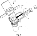
- shut-off slide 09 can be linearly adjusted by driving a drive device 10, namely a drive motor, and thereby opened or closed.
Landscapes
- Engineering & Computer Science (AREA)
- Mechanical Engineering (AREA)
- General Engineering & Computer Science (AREA)
- Air-Flow Control Members (AREA)
- Electric Vacuum Cleaner (AREA)
- Nozzles For Electric Vacuum Cleaners (AREA)
Description
Die Erfindung betrifft eine Zentralsauganlage nach dem Oberbegriff des Anspruchs 1. Weiter betrifft die Erfindung ein Verfahren zum Betrieb einer Zentralsauganlage.The invention relates to a central suction system according to the preamble of claim 1. The invention also relates to a method for operating a central suction system.
Zentralsauganlagen der gattungsgemäßen Art sind aus dem Stand der Technik bekannt und finden breite Anwendung. Grundgedanke der Zentralsauganlage ist es, dass eine zentrale Saugeinheit in einem Gebäude, beispielsweise im Kellergeschoss platziert wird, wobei zugleich in den einzelnen zu reinigenden Räumen jeweils Zapfstellen vorgesehen sind, an denen Saugluft mit einem Reinigungsgerät, beispielsweise einer Bodensaugdüse mit zugeordnetem Schlauchanschluss angeschlossen werden kann. Die zentrale Saugeinheit kann auch mehrere Aggregate bzw. Staubauffangbehälter umfassen. Die Zapfstellen werden mit der zentralen Saugeinheit über Saugleitungen verbunden, so dass die zentral durch die zentrale Saugeinheit geförderte Saugluft ausgehend von den jeweils geöffneten Zapfstellen durch die Saugleitungen abgesaugt werden kann. Vorteil ist es dabei, dass das in den zu reinigenden Räumen verwendete Reinigungsgerät keinen eigenen Antrieb zum Ansaugen der Saugluft und keine eigene Filtereinrichtung zum Abfiltern des abgesaugten Staubs benötigt. Diese Funktionalitäten werden vielmehr in der zentralen Saugeinheit realisiert, so dass sich entsprechende Kostenvorteile ergeben. Darüber hinaus kommt es zu vergleichsweise weniger Staubaufwirbelung, sowie Geruchs- und Geräuschbelästigungen. Auch zu verwendende Reinigungsgeräte können außerdem dadurch erheblich leichter und einfacher ausgebildet sein. Das Dokument
Bei den bekannten Zentralsauganlagen ist an den einzelnen Zapfstellen jeweils ein Absperrorgan vorgesehen, wobei die Entnahme von Saugluft an der Zapfstelle durch Betätigung des Absperrorgans freigegeben oder abgeschalten werden kann. Das Absperrorgan kann beispielsweise in der Art einer Verschlussklappe in der Zapfstelle ausgebildet sein, die durch Einstecken des Schlauchs des jeweils verwendeten Reinigungsgeräts geöffnet wird. Im Ergebnis strömt dann die Saugluft nach Einstecken des Schlauchs in die Zapfstelle durch das Reinigungsgerät und ermöglicht eine Reinigung des entsprechenden Raums. Nach Abschluss der Reinigung kann dann der Schlauch wieder aus der Zapfstelle herausgezogen und dadurch die Zapfstelle verschlossen werden, so dass die Saugluft nicht unkontrolliert in die Zapfstelle eingesogen wird.In the known central suction systems, a shut-off device is provided at each tapping point, and the extraction of suction air at the tapping point can be enabled or switched off by actuating the shut-off device. The shut-off element can be designed, for example, in the manner of a closure flap in the tap, which is opened by inserting the hose of the cleaning device used in each case. As a result, the suction air then flows through the cleaning device after the hose has been inserted into the tapping point and enables the corresponding room to be cleaned. After the cleaning has been completed, the hose can be pulled out of the tap again and the tap can thereby be closed so that the suction air is not sucked into the tap in an uncontrolled manner.
Die bekannten Zentralstaubanlagen haben den Nachteil, dass bei gleichzeitiger Nutzung in mehreren Räumen, das heißt wenn mehrere Reinigungsgeräte an verschiedenen Zapfstellen gleichzeitig eingesteckt sind, ein sehr hoher Spitzenbedarf bei der erforderlichen Saugleistung vorzusehen ist. Wird eine Zentralsauganlage beispielsweise in einer Wohnanlage mit zwölf Wohnungen eingebaut, so muss die Saugleistung der Zentralsauganlage dahingehend ausgelegt werden, dass selbst bei gleichzeitiger Nutzung eines Reinigungsgeräts in allen zwölf Wohnungen für jede Wohnung ein erforderliches Mindestmaß an Saugleistung zur Verfügung steht. Bei den bekannten Zentralsauganlagen werden deshalb zum Antrieb der zentralen Saugeinheit Antriebsvorrichtungen mit sehr hoher Leistung verwendet, die einen hohen Energieverbrauch und/oder Effizienzverluste und damit entsprechend hohe Kosten verursachen.The known central dust systems have the disadvantage that when they are used in several rooms at the same time, ie when several cleaning devices are plugged in at different tapping points at the same time, a very high peak demand must be provided for the required suction power. If, for example, a central vacuum system is installed in a residential complex with twelve apartments, the suction power of the central vacuum system must be designed in such a way that even if a cleaning device is used in all twelve apartments at the same time, the required minimum suction power is available for each apartment. In the known central suction systems, drive devices with very high power are therefore used to drive the central suction unit, which cause high energy consumption and/or efficiency losses and thus correspondingly high costs.
Aufgabe der vorliegenden Erfindung ist es deshalb eine Zentralsauganlage vorzuschlagen, mit der ein Energieverbrauch beim Antrieb der zentralen Saugeinheit auch bei Versorgung von einer Vielzahl von Zapfstellen mit Saugluft reduziert werden kann. Das erfindungsgemäße Verfahren hat die Aufgabe den Einsatz der Zentralsauganlage im Hinblick auf die Reduktion der erforderlichen Spitzenlast bei der Versorgung von Zentralsauganlagen mit einer Vielzahl von Zapfstellen zu optimieren.It is therefore the object of the present invention to propose a central suction system with which energy consumption when driving the central suction unit can be reduced even when suction air is supplied from a large number of tapping points. The method according to the invention has the task of optimizing the use of the central suction system with regard to reducing the peak load required when supplying central suction systems with a large number of tapping points.
Diese Aufgabe wird durch eine Zentralsauganlage bzw. ein Verfahren zum Betrieb einer Zentralsauganlage nach der Lehre der unabhängigen Hauptansprüche gelöst.This object is achieved by a central suction system and a method for operating a central suction system according to the teaching of the independent main claims.
Vorteilhafte Ausführungsformen der Erfindung sind Gegenstand der Unteransprüche.Advantageous embodiments of the invention are the subject matter of the dependent claims.
Die erfindungsgemäße Zentralstaubanlage wird dadurch charakterisiert, dass die den Zapfstellen jeweils zugeordneten Absperrorgane durch Ansteuerung einer Antriebseinrichtung zwischen einer Sperrstellung und einer Öffnungsstellung verstellbar sind. Befindet sich das Absperrorgan in der Sperrstellung ist es geschlossen, so dass Saugluft an der entsprechenden Zapfstelle nicht entnommen werden kann. Befindet sich das Absperrorgan in der Öffnungsstellung ist es geöffnet und Saugluft kann mit dem Reinigungsgerät an der Zapfstelle entnommen werden.The central dust system according to the invention is characterized in that the shut-off devices assigned to the taps can be adjusted between a blocked position and an open position by controlling a drive device. If the shut-off element is in the blocking position, it is closed so that suction air cannot be drawn off at the corresponding tapping point. If the shut-off device is in the open position, it is open and suction air can be drawn off with the cleaning device at the tapping point.
Erfindungsgemäß ist es vorgesehen, dass die Antriebseinrichtung zum Öffnen und Schließen des Absperrorgans mit einer Bedieneinrichtung durch einen Benutzer fernsteuerbar ist. Dies bedeutet mit anderen Worten, dass das Absperrorgan nicht mehr unmittelbar durch den Benutzer betätigt wird, sondern stattdessen die Betätigung durch Ansteuerung der Antriebseinrichtung des Absperrorgans mittels der Bedieneinrichtung erfolgt. Erfindungsgemäß wird es dadurch möglich, das Absperrorgan als fernsteuerbares Stellglied in der Zentralsauganlage zu verwenden und dadurch im Hinblick auf die erforderliche Spitzenlast der Zentralsauganlage unerwünschte Mehrfachnutzungen durch die gleichzeitige Entnahme von Saugluft an zu vielen Zapfstellen gleichzeitig auszuschließen.According to the invention, it is provided that the drive device for opening and closing the shut-off element can be remotely controlled by a user with an operating device. In other words, this means that the shut-off element is no longer actuated directly by the user, but instead is actuated by actuating the drive device of the shut-off element by means of the operating device. According to the invention, this makes it possible to use the shut-off element as a remote-controllable actuator in the central suction system and thereby with regard to the required peak load of the central suction system prevent undesired multiple uses through the simultaneous extraction of suction air from too many tapping points at the same time.
In welcher Weise die Bedienbefehle des Benutzers von der Bedieneinrichtung an die Antriebseinrichtung des Absperrorgans übermittelt werden, ist grundsätzlich beliebig. Besonders komfortabel und einfach gelingt dies, wenn die Bedieneinrichtung eine drahtlose Kommunikationsschnittstelle zur drahtlosen Ansteuerung der Antriebseinrichtung aufweist. Beispielsweise können Bedienbefehle mittels einer Fernbedienung und/oder durch Sprachbefehle übermittelt werden. Dadurch wird es insbesondere vermieden, dass eine Vielzahl von Kommunikationskabeln im Gebäude verlegt werden müssen.The manner in which the user's operating commands are transmitted from the operating device to the drive device of the shut-off element is fundamentally arbitrary. This is achieved in a particularly convenient and simple manner if the operating device has a wireless communication interface for wirelessly controlling the drive device. For example, operating commands can be transmitted by means of a remote control and/or by voice commands. In particular, this avoids having to lay a large number of communication cables in the building.
Um dem Benutzer eine besonders komfortable Benutzung im Hinblick auf das Ein- und Ausschalten einer Zapfstelle zu ermöglichen, ist es vorteilhaft, wenn die Bedieneinrichtung zur Ansteuerung der Antriebeinrichtung des Absperrorgans in das an die Zapfstelle anschließbare Reinigungsgerät eingebaut ist. Dies kann insbesondere durch die Verwendung einer drahtlosen Kommunikationsschnittstelle stark vereinfacht werden. Will der Benutzer nunmehr einen Raum reinigen, so kann er nach Anschluss des Schlauchs an die Zapfstelle die Saugluft durch Betätigung der am Reinigungsgerät selbst vorgesehenen Bedieneinrichtung einschalten. Zum Abschluss der Reinigungsarbeiten schaltet er das Absperrorgan durch entsprechende Eingabe eines Bedienbefehls an der Bedieneinrichtung in die Sperrstellung, so dass anschließend der Schlauch des Reinigungsgeräts abgenommen werden kann. Im Hinblick auf die Vermeidung einer unerwünschten Spitzenlast beim Betrieb der Zentralsauganlage durch die gleichzeitige Entnahme von Saugluft an zu vielen Zapfstellen ist es weiterhin besonders vorteilhaft, wenn das Absperrorgan ein Steuerungsmodul umfasst, das mit der Bedieneinrichtung zur Fernsteuerung des Absperrorgan ansteuerbar ist und zugleich mit der Hauptsteuerung der Zentralstaubanlage angesteuert werden kann. Im Ergebnis erhält also das Absperrorgan dann mittels des Steuerungsmoduls gleichzeitig Bedienbefehle aus der Bedieneinrichtung und aus der Hauptsteuerung der Zentralsauganlage.In order to enable the user to use it particularly conveniently with regard to switching a tap on and off, it is advantageous if the operating device for controlling the drive device of the shut-off element is built into the cleaning device that can be connected to the tap. This can be greatly simplified in particular by using a wireless communication interface. If the user now wants to clean a room, after connecting the hose to the tapping point, he can switch on the suction air by operating the operating device provided on the cleaning device itself. At the end of the cleaning work, he switches the shut-off element to the blocked position by entering an operating command on the operating device, so that the hose of the cleaning device can then be removed. With regard to avoiding an undesired peak load when operating the central suction system due to the simultaneous extraction of suction air at too many tapping points, it is also particularly advantageous if the shut-off device includes a control module that can be controlled with the operating device for remote control of the shut-off device and at the same time with the main control of the central dust system can be controlled. As a result, the shut-off device then receives operating commands at the same time by means of the control module from the operating device and from the main control of the central vacuum system.
Die Art und Weise der Datenkommunikation zwischen dem Steuerungsmodul vom Absperrorgan und der Hauptsteuerung der Zentralsauganlage ist grundsätzlich beliebig. Zur Vermeidung der Notwendigkeit zur Verlegung einer Vielzahl von Kommunikationsleitungen ist es besonders vorteilhaft, wenn die Daten über ein Bussystem ausgetauscht werden. Dadurch reicht die Verlegung einer gemeinsamen Datenbusleitung zwischen allen Steuerungsmodulen an den verschiedenen Zapfstellen und der Hauptsteuerung der Zentralsauganlage aus.The type of data communication between the control module of the shut-off device and the main control of the central vacuum system is basically arbitrary. In order to avoid the need to lay a large number of communication lines, it is particularly advantageous if the data are exchanged via a bus system. As a result, it is sufficient to lay a common data bus line between all control modules at the various tapping points and the main control of the central vacuum system.
Im Hinblick auf die effiziente Nutzung der von der zentralen Saugeinheit zur Verfügung gestellten Saugleistung ist es weiterhin vorteilhaft, wenn die zentrale Saugeinheit durch Ansteuerung der Steuerungsmodule im Absperrorgan ein- und ausschaltbar und/oder, dass die Saugleistung der zentralen Saugeinheit durch Ansteuerung des Steuermoduls im Absperrorgan veränderbar ist. Dadurch gelingt es, die von der zentralen Saugeinheit zur Verfügung gestellte Saugleistung bedarfsgerecht auf die Anzahl der gleichzeitig geöffneten Zapfstellen abzustimmen. Außerdem kann die zentrale Saugeinheit in den Fällen, dass keiner Zapfstelle Saugluft entnommen wird, in einen Ruhezustand versetzt werden.With regard to the efficient use of the suction power provided by the central suction unit, it is also advantageous if the central suction unit can be switched on and off by activating the control module in the shut-off element and/or that the suction power of the central suction unit can be increased by activating the control module in the shut-off element is changeable. This makes it possible to adapt the suction power provided by the central suction unit to the number of taps that are open at the same time. In addition, the central suction unit can be put into an idle state in cases where suction air is not being drawn from any tapping point.
Gemäß einer bevorzugten Ausführungsform ist es vorgesehen, dass die Zentralsauganlage ein Zeitglied umfasst, mit dem die Nutzungsdauer bei der Entnahme von Saugluft an der Zapfstelle erfassbar ist, und/oder mit dem das Absperrorgan nach Ablauf einer vorgegebenen maximalen Nutzungsdauer abgeschaltet werden kann. Im Ergebnis kann somit durch Einsatz des Zeitglieds die jeweilige Nutzungsdauer bei der Entnahme von Saugluft an den einzelnen Zapfstellen registriert und zur Abrechnung gegenüber den Benutzern eingesetzt werden. Die Überwachung der maximalen Nutzungsdauer ermöglicht es, eine unerwünschte Dauernutzung nach Überschreiten einer vorgegebenen Höchstnutzungsdauer dadurch auszuschließen, dass bei Überschreiten der Höchstnutzungsdauer das Absperrorgan automatisch geschlossen wird. Um die Zentralsauganlage in ein Smart-Home-Netzwerk einbinden zu können, sollte die Zentralsauganlagen weiterhin eine entsprechende Datenschnittstelle aufweisen.According to a preferred embodiment, it is provided that the central suction system includes a timer with which the service life when suction air is removed at the tapping point can be recorded and/or with which the shut-off element can be switched off after a predetermined maximum service life has expired. As a result, by using the timer, the respective duration of use when suction air is removed at the individual taps can be registered and used for billing the users. The monitoring of the maximum period of use makes it possible to rule out undesired long-term use after exceeding a specified maximum period of use in that when the maximum period of use is exceeded the shut-off device is closed automatically. In order to be able to integrate the central vacuum system into a smart home network, the central vacuum system should also have a corresponding data interface.
Um im Falle eines Brands die Zapfstellen automatisch schließen zu können, ist es vorteilhaft, wenn an den Absperrorganen jeweils eine Rückholeinrichtung, beispielsweise eine Rückholfeder, vorgesehen ist, die das Absperrorgan bei funktionsloser Antriebseinrichtung automatisch schließt. Im Falle eines Brands und entsprechendem Stromausfall wird dadurch gewährleistet, dass die Absperrorgane automatisch schließen und dadurch die Saugleitungen verschlossen werden.In order to be able to close the taps automatically in the event of a fire, it is advantageous if a return device, for example a return spring, is provided on the shut-off devices, which automatically closes the shut-off device when the drive device is inoperative. In the event of a fire and a corresponding power failure, this ensures that the shut-off devices close automatically, thereby sealing the suction lines.
Um einen Funktionsausfall der Zentralsauganlage im Falle der Störung der Antriebseinheit in der zentralen Saugeinheit auszuschließen, ist es vorteilhaft, wenn die zentrale Saugeinheit zumindest zwei redundante Saugmodule umfasst. Fällt eines dieser Saugmodule aus, kann die erforderliche Saugleistung zumindest im beschränkten Umfang durch das verbleibende zweite Saugmodul gewährleistet werden.In order to rule out a functional failure of the central suction system in the event of a fault in the drive unit in the central suction unit, it is advantageous if the central suction unit comprises at least two redundant suction modules. If one of these suction modules fails, the required suction power can be guaranteed, at least to a limited extent, by the remaining second suction module.
Die Zentralsauganlage kann eine Schlauchaufrollvorrichtung umfassen, mittels der ein Schlauch des Reinigungsgerätes auf einer Haspel auf- und abrollbar ist.The central vacuum system can include a hose reeling device, by means of which a hose of the cleaning device can be reeled up and down on a reel.
Das erfindungsgemäße Verfahren zum Betrieb einer Zentralsauganlage wird dadurch charakterisiert, dass die Anzahl der gleichzeitig geöffneten Absperrorgane überwacht wird. Wird nun die vorgegebene Maximalanzahl von gleichzeitig geöffneten Absperrorganen überschritten, so wird dadurch die Öffnung weiterer Absperrorgane ausgeschlossen. Im Ergebnis wird durch das erfindungsgemäße Verfahren erreicht, dass die Anzahl der gleichzeitig geöffneten Absperrorgane auf eine vorgegebene Maximalanzahl begrenzt wird. Die dem Betrieb der Zentralsauganlage zur Verfügung gestellte Spitzenlast zur Erzeugung der Saugluft kann durch diese Begrenzung der Maximalanzahl von gleichzeitig geöffneten Absperrorganen und die dadurch erreichte Begrenzung der gleichzeitig genutzten Zapfstellen signifikant reduziert werden. Umfasst die Zentralsauganlage beispielsweise zwölf Zapfstellen, an denen Saugluft entnommen werden kann, so würde bei einer konventionellen Zentralsauganlage eine Auslegung der maximal erforderlichen Spitzenlast der zentralen Saugeinheit eine Auslegung auf die gleichzeitige Nutzung von Reinigungsgeräten an zwölf Zapfstellen erforderlich. Mittels des erfindungsgemäßen Verfahrens kann die Maximalanzahl von gleichzeitig geöffneten Absperrorganen beispielweise auf vier oder fünf begrenzt werden, so dass die erforderliche Spitzenlast der zentralen Saugeinheit entsprechend sinkt. Für den praktischen Gebrauch der Zentralsauganlage bedeutet diese Begrenzung der Maximalanzahl von gleichzeitig geöffneten Absperrorganen in aller Regel keine maßgebliche Einschränkung, da das gleichzeitige Öffnen einer größeren Anzahl von Absperrorganen in nur sehr seltenen Ausnahmefällen vorkommt. Sind in der Zentralsauganlage alle Zapfstellen geschlossen, so wird keine Saugluft entnommen und der Antrieb der zentralen Saugeinheit ist nicht erforderlich. Um einen unnützen Antrieb der zentralen Saugeinheit in diesen Fällen zu vermeiden, ist es gemäß einer bevorzugten Verfahrensvariante vorgesehen, dass die zentrale Saugeinheit erst beim Öffnen des ersten Absperrorgans eingeschaltet und beim Schließen des letzten Absperrorgans wieder abgeschaltet wird. Dies bedeutet mit anderen Worten, dass die zentrale Saugeinheit nur dann Saugluft zur Verfügung stellt, wenn zumindest ein Absperrorgan geöffnet wird. Sind dagegen alle Absperrorgane geschlossen, wird die zentrale Saugeinheit in einen Ruhezustand versetzt, bei dem im Wesentlichen keine Betriebsenergie verbraucht wird.The method according to the invention for operating a central suction system is characterized in that the number of shut-off devices that are open at the same time is monitored. If the specified maximum number of shut-off devices that are open at the same time is now exceeded, the opening of further shut-off devices is ruled out. As a result, the method according to the invention ensures that the number of shut-off devices that are open at the same time is limited to a predetermined maximum number. The peak load provided for the operation of the central suction system to generate the suction air can be reduced by limiting the maximum number of shut-off devices that are open at the same time and the resulting limitation of the tapping points used at the same time can be significantly reduced. For example, if the central vacuum system has twelve tapping points from which suction air can be drawn, a conventional central vacuuming system would require a design for the maximum required peak load of the central vacuum unit to allow for the simultaneous use of cleaning devices at twelve tapping points. By means of the method according to the invention, the maximum number of shut-off elements that are open at the same time can be limited to four or five, for example, so that the required peak load of the central suction unit decreases accordingly. For the practical use of the central suction system, this limitation of the maximum number of shut-off devices that are open at the same time does not usually mean a significant restriction, since the simultaneous opening of a larger number of shut-off devices only occurs in very rare exceptional cases. If all tapping points in the central suction system are closed, no suction air is extracted and the drive of the central suction unit is not required. In order to avoid unnecessary driving of the central suction unit in these cases, according to a preferred variant of the method, the central suction unit is only switched on when the first shut-off element is opened and switched off again when the last shut-off element is closed. In other words, this means that the central suction unit only makes suction air available when at least one shut-off element is opened. If, on the other hand, all the shut-off devices are closed, the central suction unit is put into an idle state in which essentially no operating energy is consumed.
Durch Einsatz des erfindungsgemäßen Verfahrens wird die Anzahl der gleichzeitig geöffneten Absperrorgane auf eine vorgegebene Maximalanzahl begrenzt. Wird diese Maximalanzahl unterschritten kann dann das Absperrorgan an einer anderen Zapfstelle geöffnet werden. Bei der Reinigung eines Raums ergibt sich dadurch das Problem, dass beispielsweise das Reinigungsgerät in einem Raum in einer kurzen Reinigungspause abgeschaltet wird. Wird nun ein Absperrorgan an einer anderen Zapfstelle geöffnet, wäre das erneute Öffnen des Absperrorgans an der ersten Zapfstelle gesperrt und die Reinigungsarbeiten könnten in diesem Raum nicht fortgesetzt werden. Zur Vermeidung dieses Problems ist es deshalb gemäß einer bevorzugten Verfahrensvariante vorgesehen, dass bei Unterschreiten der vorgegebenen Maximalzahl von gleichzeitig geöffneten Absperrorgangen durch Schließen eines Absperrorgans in einer Reinigungspause das Öffnen eines anderen Absperrorgans bis zum Ablauf einer vorgegebenen Latenzzeit ausgeschlossen bleibt. Während dieser Latenzzeit hat der Nutzer während einer Reinigungspause die Möglichkeit während dieser Zeit eine erneute Öffnung des Absperrorgans an seiner Zapfstelle anzufordern. Erst wenn die Latenzzeit abgelaufen ist, kann dann ein anderer Benutzer an einer anderen Zapfstelle die Öffnung des jeweils zugeordneten Absperrorgans anfordern. Um den Benutzer über die Möglichkeit zur erneuten Öffnung seines Absperrorgans zu informieren, ist es vorteilhaft, wenn die Latenzzeit mit einer Signalisierungseinrichtung, Beispielsweise an einem Bildschirm angezeigt wird, um dem Benutzer über die Möglichkeit zum erneuten Öffnen des zuvor geschlossenen Absperrorgans zu informieren. Insbesondere kann der Benutzer dadurch auch darüber informiert werden, zu welchem Zeitpunkt die Latenzzeit abläuft, so dass er seine Reinigungspause vor Ablauf der Latenzzeit unterbricht und das Absperrorgan durch Eingabe eines entsprechenden Bedienbefehls wieder öffnet. Optional kann die Latenzzeit auch dynamisch geändert werden, beispielsweise situationsabhängig nach der Anzahl der aktiven Benutzer und/oder nicht bedienbaren Sauganforderungen.By using the method according to the invention, the number of shut-off devices that are open at the same time is limited to a predetermined maximum number. If this maximum number is not reached, the shut-off device can be opened at another tapping point. When cleaning a room, the problem arises that, for example, the cleaning device in a room is switched off during a short break in cleaning becomes. If a shut-off device is now opened at another tapping point, the re-opening of the shut-off device at the first tapping point would be blocked and the cleaning work could not be continued in this room. To avoid this problem, according to a preferred variant of the method, it is therefore provided that if the specified maximum number of shut-off elements open at the same time is not reached by closing one shut-off element during a cleaning break, the opening of another shut-off element is ruled out until a predetermined latency period has elapsed. During this latency period, the user has the option during a cleaning break to request a reopening of the shut-off element at his tap. Only when the latency period has expired can another user at another tapping point request the opening of the respectively assigned shut-off device. In order to inform the user about the possibility of reopening his shut-off element, it is advantageous if the latency time is displayed with a signaling device, for example on a screen, in order to inform the user about the possibility of reopening the previously closed shut-off element. In particular, the user can also be informed as to when the latency time expires, so that he interrupts his cleaning break before the latency time expires and opens the shut-off element again by entering a corresponding operating command. Optionally, the latency can also be changed dynamically, for example depending on the situation according to the number of active users and/or non-servicable suction requests.
Um eine nutzungsgerechte Abrechnung der Kosten für den Betrieb der Zentralsauganlage zu ermöglichen, ist es besonders vorteilhaft, wenn nach Öffnen eines Absperrorgans die Nutzungsdauer bei der Entnahme von Saugluft an der zugeordneten Zapfstelle erfasst wird. Diese Nutzungsdauer kann dann zur Grundlage einer entsprechenden Nutzungsgebühr für die Nutzung der Zentralsauganlage verwendet werden.In order to allow usage-based billing of the costs for the operation of the central suction system, it is particularly advantageous if, after opening a shut-off device, the period of use is recorded when suction air is removed from the assigned tapping point. This period of use can then be used as the basis for a corresponding user fee for using the central vacuum system.
Wird der Bediener bei Durchführung von Reinigungsarbeiten unterbrochen, so kann es vorkommen, dass das Absperrorgan geöffnet bleibt obwohl keine Reinigungsarbeiten mehr ausgeführt werden. Dadurch würde die Nutzung von Saugluft an anderen Zapfstellen möglicherweise unmöglich gemacht. Um dies zu verhindern, kann bei Überschreiten einer vorgegebenen maximalen Nutzungsdauer das Absperrorgan automatisch geschlossen werden. Beispielsweise kann das Absperrorgan nach Ablauf einer maximalen Nutzungsdauer von beispielsweise 30 Minuten automatisch geschlossen werden, da diese Zeit zur Reinigung eines Raums üblicherweise problemlos ausreicht.If the operator is interrupted while carrying out cleaning work, it can happen that the shut-off device remains open although cleaning work is no longer being carried out. This would possibly make the use of suction air at other tapping points impossible. In order to prevent this, the shut-off element can be closed automatically when a predetermined maximum period of use is exceeded. For example, the shut-off device can be automatically closed after a maximum period of use of 30 minutes, for example, since this time is usually sufficient to clean a room without any problems.
Im Hinblick auf die effiziente Nutzung der Antriebsleistung zum Antrieb der zentralen Saugeinheit ist es vorteilhaft, wenn die Saugleistung der zentralen Saugeinheit in Abhängigkeit von der Anzahl der gleichzeitig geöffneten Absperrorgane verändert wird. Sind beispielsweise lediglich zwei Zapfstellen geöffnet, wird eine geringere Saugleistung benötigt, als wenn Saugluft gleichzeitig an vier, fünf oder sechs Zapfstellen entnommen wird.With regard to the efficient use of the drive power for driving the central suction unit, it is advantageous if the suction power of the central suction unit is changed as a function of the number of shut-off devices that are open at the same time. For example, if only two taps are open, a lower suction power is required than if suction air is drawn off at four, five or six taps at the same time.
Die Saugleitungen können mit einer oder mehreren Steigleitungen mit Abzweigungen innerhalb einer oder mehrerer Etagen eines Gebäudes oder auch mit einer oder mehreren Ringleitungen mit Abzweigungen ausgebildet sein.The suction lines can be formed with one or more risers with branches within one or more floors of a building or with one or more loops with branches.
Eine Ausführungsform der Erfindung ist den Zeichnungen schematisiert dargestellt und wird nachfolgend beispielhaft erläutert.An embodiment of the invention is shown schematically in the drawings and is explained below by way of example.
Es zeigen:
- Fig. 1
- das Aufbauschema einer erfindungsgemäßen Zentralsauganlage;
- Fig. 2
- das Absperrorgan an einer Zapfstelle der Zentralsauganlage gemäß
Fig. 1 in perspektivischer seitlicher Ansicht.
- 1
- the structural diagram of a central suction system according to the invention;
- 2
- the shut-off device at a tapping point of the central vacuum system
1 in perspective side view.
An jeder der Zapfstellen 02 kann ein Reinigungsgerät 11, beispielsweise eine Saugdüse mit entsprechendem Anschlussschlauch angeschlossen werden. Jeder Zapfstelle 02 ist ein Absperrorgan 06 vorgeordnet, wobei die Entnahme von Saugluft an einer Zapfstelle 02 durch Betätigung des Absperrorgans freigegeben oder abgeschaltet werden kann. Wie hier beispielhaft dargestellt, kann ein Schlauch 17 des Reinigungsgeräts 11 auch optional auf einer Haspel 16 einer Schlauchaufrollvorrichtung 15 aufund abrollbar angeordnet sein.A
Über eine Datenbusleitung 12 werden die Steuerungsmodule in den Absperrorganen 06 mit Bedieneinrichtungen 07 und der Hauptsteuerung 13 der Zentralsauganlage 01 verbunden. Die Bedieneinrichtungen 07 sind in der Art von Touchscreens ausgebildet, an denen der Benutzer seine Bedienbefehle, beispielsweise manuell oder als Sprachbefehle, eingeben kann. Die in den Absperrorganen 06 vorgesehenen Steuerungsmodule weisen außerdem eine drahtlose Kommunikationsschnittstelle auf, um Bedienbefehle per Funk von einer in das Reinigungsgerät 11 eingebauten Bedieneinrichtung 08 annehmen zu können.The control modules in the shut-off
Will ein Benutzer in einem Raum Reinigungsarbeiten unter Verwendung des Reinigungsgeräts 11 durchführen, wird zunächst der Schlauch des Reinigungsgeräts 11 an die Zapfstelle 02 angeschlossen, und anschließend durch Eingabe eines Bedienbefehls an den Bedieneinrichtungen 07 bzw. 08 das der jeweiligen Zapfstelle 02 zugeordnete Absperrorgan 06 geöffnet. Durch das Öffnen des Absperrorgans 06 wird die Luft durch das Reinigungsgerät 11 in die Zapfstelle 02 von dort durch die Saugleitungen 05 in die zentrale Saugeinheit 03 eingesogen. Wie hier beispielhaft dargestellt kann die Zapfstelle 02 auch eine Mehrzahl von parallel geschalteten Anschlüssen 14 umfassen, die dem Absperrorgan 06 der Zapfstelle 02 nachgeschaltet sind und einen Anschluss eines Reinigungsgeräts 11 ermöglichen.If a user wants to carry out cleaning work in a room using the
Durch die Bedieneinheit 07 kann dem Benutzer der Status der Zentralsauganlage für seinen Nutzungsbereich angezeigt werden. Die Anzeige umfasst hier beispielhaft vier Statusmeldungen, nämlich, die Statusmeldung "BEREIT", die Statusmeldung "AKTIV", die Statusmeldung "BELEGT" und die Statusmeldung "STÖRUNG/SERVICE". Weitere Statusmeldungen sind möglich. Außerdem können an der Bedieneinrichtung 07 weitere Parameter, beispielsweise die bisher benutzten Betriebsstunden bzw. die Betriebsstunden des letzten Monats oder der letzten Woche oder Ähnliches angezeigt werden.The operating
Die in
Wird davon ausgegangen, dass zunächst alle Absperrorgane 06 geschlossen sind, befindet sich die zentrale Saugeinheit in ihrem Ruhezustand und die Saugmotoren sind abgeschaltet. Wird nun eine Zapfstelle 02 in Betrieb genommen und durch Öffnen des zugeordneten Absperrorgans 06 Saugluft gezapft, so wird die entsprechende Anforderung über die Busleitung 12 an die Hauptsteuerung 13 übermittelt und dort registriert. An der jeweils zugeordneten Bedieneinheit 07 wird dann die Statusanzeige "AKTIV" angezeigt. Alle anderen Bedieneinheiten 07 zeigen die Statusanzeige "BEREIT".If it is assumed that initially all shut-off
Werden nun zwei weitere Absperrorgane 06 durch Eingabe entsprechender Bedienbefehle geöffnet, so wird dies in der Hauptsteuerung 13 registriert, da nach Öffnen von drei Absperrorganen 06 die Maximalanzahl von gleichzeitig geöffneten Absperrorganen erreicht ist, werden die an den geöffneten Absperrorganen 06 zugeordneten Bedieneinheiten 07 die Statusanzeigen auf "AKTIV" gesetzt, wohingegen die fünf anderen Bedieneinheiten die Statusanzeige "BELEGT" anzeigen. Das Öffnen der Absperrorgane an diesen anderen fünf Zapfstellen 02 ist dadurch gesperrt, um eine unerwünschte Aufteilung der Saugleistung auf mehr als drei Zapfstellen 02 auszuschließen. In einem Zeitglied wird die Zeit seit Öffnen des jeweils zugeordneten Absperrorgans registriert. Nach Ablauf einer maximalen Nutzungsdauer von beispielsweise 15 Minuten wird das Absperrorgan 06 automatisch geschlossen, um ein ungewolltes dauerhaftes Öffnen des Absperrorgans und die entsprechende Sperrung an anderen Absperrorganen zu vermeiden.If two further shut-off
Unterbricht ein Verwender die Reinigungsarbeiten an einer der Zapfstellen 02 durch Eingabe eines entsprechenden Bedienbefehls, so wird die Zeit seit Fließen des zugeordneten Absperrorgans 06 im Zeitglied registriert und mit einer Latenzzeit verglichen. Erst nach Ablauf der vorgegebenen Latenzzeit von beispielsweise drei Minuten, kann ein anderes Absperrorgan 06 durch einen anderen Verwender geöffnet werden, falls bereits zwei weitere Verwender aktiv sind. Wenn maximal zwei Verwender aktiv sind wechselt in diesem Fall die Anzeige an der Bedieneinrichtung 07 von der Statusanzeige "BELEGT" auf die Statusanzeige "BEREIT". Während der Latenzzeit soll die Statusanzeige an der entsprechenden Bedieneinrichtung farbig markiert sein und/oder blinken, um den Verwender anzuzeigen, dass er während der Latenzzeit problemlos und unabhängig von anderen Verwendern das Absperrorgan jederzeit wieder öffnen kann.If a user interrupts the cleaning work at one of the
Während der Latenzzeit muss das zugeordnete Absperrventil geschlossen bleiben. Für den Fall, dass der Benutzer zu diesem Zeitpunkt der einzige aktive Verwender der Zentralsauganlage 01 war, werden auch die Motoren in der zentralen Saugeinheit 03 abgeschaltet. Dies bedeutet im Ergebnis, dass die Saugmotoren immer eingeschaltet bleiben, wenn mindestens ein Absperrorgan 06 geöffnet ist.During the latency period, the associated shut-off valve must remain closed. In the event that the user was the only active user of the
Claims (19)
- A central suction system (01) comprising at least one central suction unit (03) and multiple extraction points (02) at which suction air can be extracted using a cleaning device (11), the central suction unit (03) being connected to the extraction points (02) via suction pipes (05), and a shut-off valve (06) being associated with each extraction point (02), and the extraction of suction air at an extraction point (02) being unlocked and locked by operating the shut-off valve (06),
characterized in that
the shut-off valve (06) is adjustable between a shut-off position and an open position by actuating a drive member (10), and the shut-off valve (06) being closed when in the shut-off position, and the shut-off valve (06) being open when in the open position, and the drive member being configured for being remote-controlled by a user by means of a control member (07, 08) to open and close the shut-off valve (06). - The central suction system according to claim 1,
characterized in that
the control member (08) has a wireless communication interface for wirelessly actuating the shut-off valve (06). - The central suction system according to claim 1 or 2,
characterized in that
the control member (08) is installed in a cleaning device (11) which is connectable to an extraction point (02). - The central suction system according to any one of claims 1 to 3,
characterized in that
the control member (07) is a control unit, in particular a touch display, which can be attached to a structure. - The central suction system according to any one of claims 1 to 4,
characterized in that
the shut-off valve (06) comprises a control module configured to be actuated by means of the control member (07, 08) to remotely control the shut-off valve (06), the control module being additionally configured to be actuated by means of a main control (13) of the central suction system (01). - The central suction system according to claim 5,
characterized in that
the control module of the shut-off valve (06) comprises a communication interface by means of which the control module can exchange data with the main control (13) of the central suction system (01) via a data bus line (12). - The central suction system according to claim 5 or 6,
characterized in that
the central suction unit (03) is configured to be turned on and off by actuating the control module in the shut-off valve (06), and/or the suction power of the central suction unit (03) is configured to be changed by actuating the control module in the shut-off valve (06). - The central suction system according to any one of claims 1 to 7,
characterized in that
the central suction system (01) comprises a timing element, the timing element being configured to detect the use time during the extraction of suction air at an extraction point (02), and/or the timing element being configured to shut off the shut-off valve (06) after a predetermined maximum use time has elapsed. - The central suction system according to any one of claims 1 to 8,
characterized in that
the central suction system (01) comprises a data interface for integration into a smart home network. - The central suction system according to any one of claims 1 to 9,
characterized in that
the shut-off valve (06) has a return mechanism, the return mechanism automatically closing the shut-off valve when the drive member (10) is inoperable. - The central suction system according to any one of claims 1 to 10,
characterized in that
the central suction unit (03) comprises at least two redundant suction modules (04). - The central suction system according to any one of claims 1 to 11,
characterized in that
the central suction system (01) comprises a hose reel device (15) configured to coil and uncoil a hose (17) of the cleaning device (11) on a reel (16). - A method for operating a central suction system (01) comprising at least one central suction unit (03) and multiple extraction points (02) at which suction air can be extracted using a cleaning device (11), the central suction unit (03) being connected to the extraction points (02) via suction pipes (05), and a shut-off valve (06) being associated with each extraction point (02), and the extraction of suction air at an extraction point (02) being unlocked and locked by operating the shut-off valve, and the shut-off valve (06) being adjustable between a shut-off position and an open position by actuating a drive member (10), and the shut-off valve (06) being closed when in the shut-off position, and the shut-off valve (06) being open when in the open position,
characterized in that
the drive member (10) is controlled remotely by a user by means of a control member (07, 08) to open and close the shut-off valve (06), the number of shut-off valves (06) open at the same time being monitored, and the opening of more shut-off valves (06) being precluded if a predetermined maximum number of shut-off valves (06) open at the same time is exceeded. - The method according to claim 13,
characterized in that
the central suction unit (03) in the central suction system (01) is turned on when the first shut-off valve (06) is opened and turned off when the last shut-off valve (06) is closed. - The method according to claim 13 or 14,
characterized in that
if the number of shut-off valves (06) open at the same time drops below the predetermined maximum number because one shut-off valve (06) has been closed, opening another shut-off valve (06) is precluded until a predetermined latency period has elapsed. - The method according to claim 15,
characterized in that
during the latency period, a signaling device indicates that the previously closed shut-off valve (06) can be opened again. - The method according to any one of claims 13 to 16,
characterized in that
after opening a shut-off valve, the use time during the extraction of suction air at the associated extraction point (06) is detected. - The method according to any one of claims 13 to 17,
characterized in that
the shut-off valve (06) is automatically closed if a predetermined maximum use time is exceeded. - The method according to any one of claims 13 to 18,
characterized in that
the suction power of the central suction unit (03) is changed as a function of the number of shut-off valves (06) open at the same time.
Applications Claiming Priority (1)
| Application Number | Priority Date | Filing Date | Title |
|---|---|---|---|
| DE102020104812 | 2020-02-24 |
Publications (2)
| Publication Number | Publication Date |
|---|---|
| EP3878332A1 EP3878332A1 (en) | 2021-09-15 |
| EP3878332B1 true EP3878332B1 (en) | 2022-10-19 |
Family
ID=74732643
Family Applications (2)
| Application Number | Title | Priority Date | Filing Date |
|---|---|---|---|
| EP21158764.7A Active EP3868269B1 (en) | 2020-02-24 | 2021-02-23 | Shut-off device for arrangement in a suction line of a central vacuum system |
| EP21158767.0A Active EP3878332B1 (en) | 2020-02-24 | 2021-02-23 | Central suction system and method for operating a central suction system |
Family Applications Before (1)
| Application Number | Title | Priority Date | Filing Date |
|---|---|---|---|
| EP21158764.7A Active EP3868269B1 (en) | 2020-02-24 | 2021-02-23 | Shut-off device for arrangement in a suction line of a central vacuum system |
Country Status (2)
| Country | Link |
|---|---|
| EP (2) | EP3868269B1 (en) |
| PL (1) | PL3878332T3 (en) |
Family Cites Families (8)
| Publication number | Priority date | Publication date | Assignee | Title |
|---|---|---|---|---|
| US5111841A (en) * | 1990-11-26 | 1992-05-12 | The Hoover Company | Central vacuum system wall valve |
| US6012199A (en) * | 1998-01-07 | 2000-01-11 | Litomisky; Petr | Refuse vacuum system for machine shops |
| DE19964219C2 (en) | 1999-08-27 | 2002-11-21 | Rolf Ferstl | Suction air barrier especially for central vacuum systems |
| CA2310962A1 (en) * | 1999-11-05 | 2001-05-05 | Shop Vac Corporation | Gate valve for a vacuum system |
| US7146677B2 (en) * | 2002-11-19 | 2006-12-12 | Ivan Litomisky | Energy saving vacuum system for particle, mist, and fume collection |
| JP5515250B2 (en) * | 2008-07-31 | 2014-06-11 | 富士通株式会社 | Dust collecting mechanism and substrate cutting device |
| KR200471735Y1 (en) * | 2013-10-01 | 2014-03-11 | (주)투엠 | Socket for Connecting Suction Pipe with Central Vacuum Cleaner |
| EP3104758B1 (en) * | 2014-02-10 | 2020-11-25 | Les Industries Trovac Ltée | Outlet box system for central vacuum systems |
-
2021
- 2021-02-23 EP EP21158764.7A patent/EP3868269B1/en active Active
- 2021-02-23 EP EP21158767.0A patent/EP3878332B1/en active Active
- 2021-02-23 PL PL21158767.0T patent/PL3878332T3/en unknown
Also Published As
| Publication number | Publication date |
|---|---|
| PL3878332T3 (en) | 2023-03-06 |
| EP3868269A1 (en) | 2021-08-25 |
| EP3878332A1 (en) | 2021-09-15 |
| EP3868269B1 (en) | 2024-04-03 |
Similar Documents
| Publication | Publication Date | Title |
|---|---|---|
| EP2672870B1 (en) | Method for cleaning of a filter of a vacuum cleaner and vacuum cleaner for carrying out said method. | |
| EP2046183B1 (en) | Method for cleaning the filters of a vacuum cleaner and vacuum cleaner for carrying out the method | |
| DE69630091T2 (en) | Lifting device for a suction grille | |
| EP1764020B1 (en) | Suction device | |
| EP2612582B1 (en) | Vacuum cleaner and method for operating same | |
| DE102006032389A1 (en) | Wind farm and method for operating a wind farm | |
| WO2012146721A1 (en) | Electric-motor furniture drive | |
| DE202004012911U1 (en) | Suction device with several suction motors | |
| WO2005045234A1 (en) | Method for diagnosis in a fuel injection device comprising a piezoactuator | |
| EP1127987B1 (en) | Flushing device for toilets | |
| EP3878332B1 (en) | Central suction system and method for operating a central suction system | |
| EP0877897A1 (en) | Method and device for drawing condensate off from compressed-gas systems | |
| DE9313983U1 (en) | Configuration for complex control of sanitary facilities | |
| DE60116779T2 (en) | FILTER FOR DIESEL FUEL | |
| EP2228145A2 (en) | Method and device for cleaning a suction system for a rotary press | |
| WO2021001152A1 (en) | Suction appliance and method for cleaning a filter | |
| EP1775479A2 (en) | Pneumatic compressed air preparation unit | |
| DE102006016080A1 (en) | Power supply device for a plurality of consumers to be connected thereto | |
| DE3722537A1 (en) | Suction device for paint spray booths | |
| DE102006051133B3 (en) | House installation, has residence stations and door station that are attached to bus and are switched-off in response to door opener signal in base with respect to energy supply of bus | |
| EP1204011A2 (en) | Valve assembly to be mounted in the water supply pipe of a water dispensing fitting | |
| EP1312799A2 (en) | Starting device for internal combustion engines | |
| EP2672871B1 (en) | Vacuum cleaner and method for cleaning a filter | |
| DE60314230T2 (en) | MIXER BATTERY WITH IMPROVED DISCHARGE CONTROL | |
| AT371183B (en) | WATER SUPPLY OR WATER DISPOSAL SYSTEM FOR HOEUSER |
Legal Events
| Date | Code | Title | Description |
|---|---|---|---|
| PUAI | Public reference made under article 153(3) epc to a published international application that has entered the european phase |
Free format text: ORIGINAL CODE: 0009012 |
|
| STAA | Information on the status of an ep patent application or granted ep patent |
Free format text: STATUS: THE APPLICATION HAS BEEN PUBLISHED |
|
| AK | Designated contracting states |
Kind code of ref document: A1 Designated state(s): AL AT BE BG CH CY CZ DE DK EE ES FI FR GB GR HR HU IE IS IT LI LT LU LV MC MK MT NL NO PL PT RO RS SE SI SK SM TR |
|
| STAA | Information on the status of an ep patent application or granted ep patent |
Free format text: STATUS: REQUEST FOR EXAMINATION WAS MADE |
|
| 17P | Request for examination filed |
Effective date: 20211217 |
|
| RBV | Designated contracting states (corrected) |
Designated state(s): AL AT BE BG CH CY CZ DE DK EE ES FI FR GB GR HR HU IE IS IT LI LT LU LV MC MK MT NL NO PL PT RO RS SE SI SK SM TR |
|
| GRAP | Despatch of communication of intention to grant a patent |
Free format text: ORIGINAL CODE: EPIDOSNIGR1 |
|
| STAA | Information on the status of an ep patent application or granted ep patent |
Free format text: STATUS: GRANT OF PATENT IS INTENDED |
|
| RIC1 | Information provided on ipc code assigned before grant |
Ipc: A47L 5/38 20060101AFI20220426BHEP |
|
| INTG | Intention to grant announced |
Effective date: 20220511 |
|
| GRAS | Grant fee paid |
Free format text: ORIGINAL CODE: EPIDOSNIGR3 |
|
| GRAA | (expected) grant |
Free format text: ORIGINAL CODE: 0009210 |
|
| STAA | Information on the status of an ep patent application or granted ep patent |
Free format text: STATUS: THE PATENT HAS BEEN GRANTED |
|
| AK | Designated contracting states |
Kind code of ref document: B1 Designated state(s): AL AT BE BG CH CY CZ DE DK EE ES FI FR GB GR HR HU IE IS IT LI LT LU LV MC MK MT NL NO PL PT RO RS SE SI SK SM TR |
|
| REG | Reference to a national code |
Ref country code: GB Ref legal event code: FG4D Free format text: NOT ENGLISH |
|
| REG | Reference to a national code |
Ref country code: CH Ref legal event code: EP |
|
| REG | Reference to a national code |
Ref country code: DE Ref legal event code: R096 Ref document number: 502021000197 Country of ref document: DE |
|
| REG | Reference to a national code |
Ref country code: IE Ref legal event code: FG4D Free format text: LANGUAGE OF EP DOCUMENT: GERMAN |
|
| REG | Reference to a national code |
Ref country code: AT Ref legal event code: REF Ref document number: 1525034 Country of ref document: AT Kind code of ref document: T Effective date: 20221115 |
|
| REG | Reference to a national code |
Ref country code: SE Ref legal event code: TRGR |
|
| REG | Reference to a national code |
Ref country code: LT Ref legal event code: MG9D |
|
| REG | Reference to a national code |
Ref country code: NL Ref legal event code: MP Effective date: 20221019 |
|
| PG25 | Lapsed in a contracting state [announced via postgrant information from national office to epo] |
Ref country code: NL Free format text: LAPSE BECAUSE OF FAILURE TO SUBMIT A TRANSLATION OF THE DESCRIPTION OR TO PAY THE FEE WITHIN THE PRESCRIBED TIME-LIMIT Effective date: 20221019 |
|
| PG25 | Lapsed in a contracting state [announced via postgrant information from national office to epo] |
Ref country code: PT Free format text: LAPSE BECAUSE OF FAILURE TO SUBMIT A TRANSLATION OF THE DESCRIPTION OR TO PAY THE FEE WITHIN THE PRESCRIBED TIME-LIMIT Effective date: 20230220 Ref country code: NO Free format text: LAPSE BECAUSE OF FAILURE TO SUBMIT A TRANSLATION OF THE DESCRIPTION OR TO PAY THE FEE WITHIN THE PRESCRIBED TIME-LIMIT Effective date: 20230119 Ref country code: LT Free format text: LAPSE BECAUSE OF FAILURE TO SUBMIT A TRANSLATION OF THE DESCRIPTION OR TO PAY THE FEE WITHIN THE PRESCRIBED TIME-LIMIT Effective date: 20221019 Ref country code: FI Free format text: LAPSE BECAUSE OF FAILURE TO SUBMIT A TRANSLATION OF THE DESCRIPTION OR TO PAY THE FEE WITHIN THE PRESCRIBED TIME-LIMIT Effective date: 20221019 Ref country code: ES Free format text: LAPSE BECAUSE OF FAILURE TO SUBMIT A TRANSLATION OF THE DESCRIPTION OR TO PAY THE FEE WITHIN THE PRESCRIBED TIME-LIMIT Effective date: 20221019 |
|
| PG25 | Lapsed in a contracting state [announced via postgrant information from national office to epo] |
Ref country code: RS Free format text: LAPSE BECAUSE OF FAILURE TO SUBMIT A TRANSLATION OF THE DESCRIPTION OR TO PAY THE FEE WITHIN THE PRESCRIBED TIME-LIMIT Effective date: 20221019 Ref country code: LV Free format text: LAPSE BECAUSE OF FAILURE TO SUBMIT A TRANSLATION OF THE DESCRIPTION OR TO PAY THE FEE WITHIN THE PRESCRIBED TIME-LIMIT Effective date: 20221019 Ref country code: IS Free format text: LAPSE BECAUSE OF FAILURE TO SUBMIT A TRANSLATION OF THE DESCRIPTION OR TO PAY THE FEE WITHIN THE PRESCRIBED TIME-LIMIT Effective date: 20230219 Ref country code: HR Free format text: LAPSE BECAUSE OF FAILURE TO SUBMIT A TRANSLATION OF THE DESCRIPTION OR TO PAY THE FEE WITHIN THE PRESCRIBED TIME-LIMIT Effective date: 20221019 Ref country code: GR Free format text: LAPSE BECAUSE OF FAILURE TO SUBMIT A TRANSLATION OF THE DESCRIPTION OR TO PAY THE FEE WITHIN THE PRESCRIBED TIME-LIMIT Effective date: 20230120 |
|
| P01 | Opt-out of the competence of the unified patent court (upc) registered |
Effective date: 20230527 |
|
| REG | Reference to a national code |
Ref country code: DE Ref legal event code: R097 Ref document number: 502021000197 Country of ref document: DE |
|
| PG25 | Lapsed in a contracting state [announced via postgrant information from national office to epo] |
Ref country code: SM Free format text: LAPSE BECAUSE OF FAILURE TO SUBMIT A TRANSLATION OF THE DESCRIPTION OR TO PAY THE FEE WITHIN THE PRESCRIBED TIME-LIMIT Effective date: 20221019 Ref country code: RO Free format text: LAPSE BECAUSE OF FAILURE TO SUBMIT A TRANSLATION OF THE DESCRIPTION OR TO PAY THE FEE WITHIN THE PRESCRIBED TIME-LIMIT Effective date: 20221019 Ref country code: EE Free format text: LAPSE BECAUSE OF FAILURE TO SUBMIT A TRANSLATION OF THE DESCRIPTION OR TO PAY THE FEE WITHIN THE PRESCRIBED TIME-LIMIT Effective date: 20221019 Ref country code: DK Free format text: LAPSE BECAUSE OF FAILURE TO SUBMIT A TRANSLATION OF THE DESCRIPTION OR TO PAY THE FEE WITHIN THE PRESCRIBED TIME-LIMIT Effective date: 20221019 Ref country code: CZ Free format text: LAPSE BECAUSE OF FAILURE TO SUBMIT A TRANSLATION OF THE DESCRIPTION OR TO PAY THE FEE WITHIN THE PRESCRIBED TIME-LIMIT Effective date: 20221019 |
|
| PLBE | No opposition filed within time limit |
Free format text: ORIGINAL CODE: 0009261 |
|
| STAA | Information on the status of an ep patent application or granted ep patent |
Free format text: STATUS: NO OPPOSITION FILED WITHIN TIME LIMIT |
|
| PG25 | Lapsed in a contracting state [announced via postgrant information from national office to epo] |
Ref country code: SK Free format text: LAPSE BECAUSE OF FAILURE TO SUBMIT A TRANSLATION OF THE DESCRIPTION OR TO PAY THE FEE WITHIN THE PRESCRIBED TIME-LIMIT Effective date: 20221019 Ref country code: AL Free format text: LAPSE BECAUSE OF FAILURE TO SUBMIT A TRANSLATION OF THE DESCRIPTION OR TO PAY THE FEE WITHIN THE PRESCRIBED TIME-LIMIT Effective date: 20221019 |
|
| 26N | No opposition filed |
Effective date: 20230720 |
|
| PG25 | Lapsed in a contracting state [announced via postgrant information from national office to epo] |
Ref country code: MC Free format text: LAPSE BECAUSE OF FAILURE TO SUBMIT A TRANSLATION OF THE DESCRIPTION OR TO PAY THE FEE WITHIN THE PRESCRIBED TIME-LIMIT Effective date: 20221019 |
|
| REG | Reference to a national code |
Ref country code: BE Ref legal event code: MM Effective date: 20230228 |
|
| PG25 | Lapsed in a contracting state [announced via postgrant information from national office to epo] |
Ref country code: LU Free format text: LAPSE BECAUSE OF NON-PAYMENT OF DUE FEES Effective date: 20230223 |
|
| PG25 | Lapsed in a contracting state [announced via postgrant information from national office to epo] |
Ref country code: SI Free format text: LAPSE BECAUSE OF FAILURE TO SUBMIT A TRANSLATION OF THE DESCRIPTION OR TO PAY THE FEE WITHIN THE PRESCRIBED TIME-LIMIT Effective date: 20221019 |
|
| REG | Reference to a national code |
Ref country code: IE Ref legal event code: MM4A |
|
| PG25 | Lapsed in a contracting state [announced via postgrant information from national office to epo] |
Ref country code: IE Free format text: LAPSE BECAUSE OF NON-PAYMENT OF DUE FEES Effective date: 20230223 |
|
| PG25 | Lapsed in a contracting state [announced via postgrant information from national office to epo] |
Ref country code: BE Free format text: LAPSE BECAUSE OF NON-PAYMENT OF DUE FEES Effective date: 20230228 |
|
| PGFP | Annual fee paid to national office [announced via postgrant information from national office to epo] |
Ref country code: CH Payment date: 20240301 Year of fee payment: 4 |
|
| PGFP | Annual fee paid to national office [announced via postgrant information from national office to epo] |
Ref country code: SE Payment date: 20240221 Year of fee payment: 4 Ref country code: PL Payment date: 20240119 Year of fee payment: 4 Ref country code: IT Payment date: 20240229 Year of fee payment: 4 Ref country code: FR Payment date: 20240222 Year of fee payment: 4 |
|
| PGFP | Annual fee paid to national office [announced via postgrant information from national office to epo] |
Ref country code: DE Payment date: 20240422 Year of fee payment: 4 |