EP3878317A1 - Pull down bed - Google Patents
Pull down bed Download PDFInfo
- Publication number
- EP3878317A1 EP3878317A1 EP21161812.9A EP21161812A EP3878317A1 EP 3878317 A1 EP3878317 A1 EP 3878317A1 EP 21161812 A EP21161812 A EP 21161812A EP 3878317 A1 EP3878317 A1 EP 3878317A1
- Authority
- EP
- European Patent Office
- Prior art keywords
- leg
- bed frame
- bed
- control rod
- safety member
- Prior art date
- Legal status (The legal status is an assumption and is not a legal conclusion. Google has not performed a legal analysis and makes no representation as to the accuracy of the status listed.)
- Granted
Links
Images



Classifications
-
- A—HUMAN NECESSITIES
- A47—FURNITURE; DOMESTIC ARTICLES OR APPLIANCES; COFFEE MILLS; SPICE MILLS; SUCTION CLEANERS IN GENERAL
- A47C—CHAIRS; SOFAS; BEDS
- A47C17/00—Sofas; Couches; Beds
- A47C17/52—Cabinet beds; Table beds, or like beds; Wardrobe beds
Definitions
- the present invention relates to a pull down bed.
- the present invention relates to a pull down bed comprising a reclining bed frame, legs for resting on the floor/ground and a movement mechanism which is designed to rotate the legs in response to the rotation movement of the bed frame.
- pull down beds are pieces of furniture comprising a cabinet which contains therein a reclining support frame designed to support a mattress.
- the bed frame of the pull down bed is usually hinged to the side cabinet, so as to rotate between a closed position in which the bed frame is arranged vertically and completely recessed inside the cabinet, thus freeing the space otherwise occupied for other possible uses, and an open position in which the bed frame is arranged horizontally at a predetermined height from the ground, to be used as a bed.
- the bed frame is also provided with a pair of legs for resting on the ground, which are hinged on the bed frame, and in their open position support the weight of the bed.
- the pull down bed is further provided with a movement mechanism which rotates the legs on the basis of the rotation of the bed frame, so as to arrange them resting on the ground when the bed frame is in the open position and to arrange them coplanar with the bed frame when the latter is in the closed position.
- Some movement mechanisms synchronize the rotation of the bed frame with the rotation of the legs. In this way, the movement of each leg accompanies the movement of the bed frame during the opening and closing operations, and vice versa.
- the movement mechanism comprises a monolithic rigid rod, which is interposed between the cabinet and the leg, thereby creating an articulated parallelogram structure which rigidly constrains the rotation of the legs to the rotation of the bed frame.
- the leg rotates relative to the bed frame, passing from the open position to the closed position.
- This movement can be dangerous when a condition occurs in which a limb, for example a hand, is placed along the rotation path of the leg during the closing operation.
- the leg behaves like a shear by closing with a scissors-like movement into a position coplanar with the bed frame, sideways, with the consequent risk of cutting or pinching the user's hand that comes between the leg and the bed frame.
- the movement mechanism can be dangerous for a distracted user, who accidentally places a limb between the support frame and the leg, especially when the bed frame is closed with the aid of an electric motor.
- the object of the present invention is to find a simple and economical solution which can overcome the drawbacks described above.
- a pull down bed is provided as defined in claim 1 and preferably, but not necessarily, in any one of the claims dependent thereon.
- the numeral 1 indicates, as a whole, a pull down bed comprising a cabinet 3, and a bed frame 2 which is connected to the cabinet 3 so as to rotate about a horizontal axis A between a closed position and an open position.
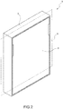
- the bed frame 2 In the closed position shown in Figure 2 , the bed frame 2 is arranged at least partially inside the cabinet 3 and lies substantially in an approximately vertical reference plane P, whereas in the open position ( Figure 1 ), the bed frame 2 is arranged, almost entirely, outside the cabinet 3 in a lowered position in which it lies in a substantially horizontal plane so that it can be used as a bed.
- the cabinet 3 may consist of a substantially box-like element, similar to a wardrobe, which is provided with a compartment 4 whose opening 5, in use, is conveniently closed by the bed frame 2 in the closed position.
- the bed frame 2 can be provided with a rectangular panel 6, for example fastened thereto at the bottom, which is structured to form a door for closing the opening 5 of the compartment 4 of the cabinet 3.
- the bed frame 2 can be preferably, but not necessarily, made of metallic material and sized to support one or more side-by-side mattresses.
- the following description will refer, without thereby losing generality, to a bed frame 2 for supporting two coplanar, side-by-side mattresses (not shown).
- the bed frame 2 comprises a preferably rectangular, perimeter frame 7 which has a longitudinal axis C and a supporting structure 8 which is stably coupled/connected to the perimeter frame 7 and forms the resting base for the mattress (not shown).
- the supporting structure 8 is formed by a plurality of side-by-side slats transverse to the longitudinal axis C and parallel to each other. It is understood that the present invention is not limited to a supporting structure 8 formed by slats, but other types of mattress support systems may be provided alternatively or additionally, such as for example wired bed frames or the like.
- the bed frame 2 is hinged/pivoted on the opposite side walls or vertical shoulders of the cabinet 3.
- the bed frame 2 is provided with two rotation pins 9 which extend in a cantilever manner on opposite sides of the bed frame 2, coaxial with the axis A, and are preferably rotatably engaged in respective openings/seats associated with the side walls of the cabinet 3.
- the pull down bed 1 further preferably comprises a shock absorber assembly 10 which is structured, on the one hand, to slow down the lowering speed of the bed frame 2 during its rotation from the closed position to the open position, and on the other hand, to exert a predetermined return force on the bed frame 2 during the movement between the open position and the closed position, so as to facilitate its rotation and the reaching of its closed position.
- the shock absorber assembly 10 is of a known type and, as it is not the object of the present invention, will not be further described herein except to point out that it can comprise one or more shock absorber devices which connect/couple the bed frame 2 to the cabinet 3.
- the pull down bed 1 further comprises at least one leg 11, preferably two legs 11, for resting on the ground, each hinged/pivoted on the bed frame 2 so as to be able to rotate about a horizontal axis B, preferably parallel to axis A, between an operating position ( Figures 1 , 3 , 5 and 6 ) and a rest position ( Figure 4 ).
- the leg 11 is hinged at the distal end of the bed frame 2, preferably by means of a pin 12, coaxial with the axis B.
- the leg 11 In the operating position, the leg 11 is approximately transverse to the plane in which the bed frame 2 lies and has its distal end resting on the ground ( Figures 1 , 3 , 5 and 6 ), whereas in the rest position, the leg 11 is approximately coplanar with the plane in which the bed frame 2 lies.
- the leg 11 preferably comprises a substantially rectangular plate optionally, but not necessarily, made of metallic material.
- a PVC base/tip suitable to protect the ground from contact with the resting end of the leg 11 is fitted on the distal end of the leg 11.
- the present invention also relates to other embodiments of the leg, for example comprising a structural shape with a cylindrical or rectangular section, and with a rectilinear or non-linear axis.
- the pull down bed 1 further comprises at least one movement mechanism 13 which is structured so that the rotation of the bed frame 2 between the open position and the closed position causes the rotation of the leg 11 between the operating position and the rest position, respectively, and vice versa.
- the movement mechanism 13 is structured so that the movement of the leg 11 between the operating position and the rest position occurs advantageously in synchronization with the rotation of the bed frame 2 between the open position and the closed position.
- the movement mechanism 13 is conveniently structured to stop the rotation movement of the leg 11 from the operating position to the rest position in response to the rotation of the bed frame 2 from the open position to the closed position, when the leg 11 encounters an obstacle in its path of rotation about the axis B.
- the movement mechanism 13 comprises at least one control rod 14 which is interposed between the cabinet 3 and a respective leg 11 and is designed to rotate the leg 11 between the operating position and the rest position in response to the rotation of the bed frame 2 between the open position and the closed position, respectively.
- the movement mechanism 13 comprises at least one safety member 15, which is structured to cooperate with a respective control rod 14, so that the rotation movement imparted by the control rod 14 to the leg 11 about the axis B from the operating position to the rest position, during the rotation of the bed frame 2, is stopped when the leg 11 is subjected to a predetermined resistance force opposite to its rotation movement, which is indicative of the presence of an obstacle along the rotation path of the leg 11.
- the control rod 14 extends substantially rectilinear along one side of the bed frame 2 and has a first end coupled/connected to the cabinet 3 by means of a hinge or a rotation pin 16, and a second end, opposite the first, which is connected by means of the safety member 15 to the leg 11 in a position eccentric to the axis B.
- the second end of the control rod 14 is connected to the leg 11 by means of a hinge or pin 17 arranged eccentrically with respect to the axis B.
- the safety member 15 further comprises at least one device structured to increase, in a controlled manner, the distance between the second free end of the control rod 14 and the hinge or pin 17 of the leg 11, so as to release the rotation movement of the leg 11 from the rotation movement of the bed frame 2 from the open position to the closed position when the leg 11 is hindered in its rotation path.
- the safety member 15 may comprise an extendable element or body, which is structured to extend axially, in a controlled manner, based on the counteracting force exerted by the leg 11 on the control rod 14, when the bed frame 2 rotates from the open position to the closed position.
- the extendable element or body of the safety member 15 is structured so as to extend axially when the counteracting force exerted by the leg 11 on the second end of the control rod 14 exceeds a predetermined safety threshold, so as to release, i.e., release mechanically, the rotation movement of the leg 11 from the rotation movement of the bed frame 2.
- the predetermined safety threshold can be conveniently defined by an operating condition indicative of the presence of an object which hinders the rotation of the leg 11 about the axis B.
- the extendable element or body of the safety member 15 can preferably be structured so as to automatically reduce, following an extension, its length to a predetermined idle length when no counteracting force is exerted by the leg 11 on the control rod 14, for example following the removal of the obstacle along the trajectory of the leg 11.
- the extendable element or body of the safety member 15 can also be structured so as to maintain the predetermined idle length unchanged when it is subjected to compression, in particular when the control rod 14 rotates the leg 11 from the rest position to the operating position in response to the rotation of the bed frame 2 from the closed position to the open position.
- the extendable element or body of the safety member 15 comprises an elastic mechanical member connected between the second end of the control rod 14 and the pin 17 of the leg 11.
- the elastic mechanical member may advantageously comprise an elastically deformable oblong element, such as for example a spring.
- the spring may preferably comprise a helical spring coaxial with the longitudinal axis of the control rod 14.
- the helical spring can be structured so that its elastic constant is associated with the predetermined safety threshold.
- the spring can also be structured to have, at rest, the predetermined idle length.
- the spring can be structured so that its extension is such as to allow the leg 11 to be released from the bed frame 2 in case of impact of the leg 11 with an obstacle.
- the longitudinal elastic constant of the helical spring of the safety member 15 is preferably sized so that, on the one hand, the helical spring rotates the leg 11 in the absence of interference along the rotation path thereof, and on the other, it extends and keeps the leg 11 in the open position when the latter encounters a resistance during the closing of the bed frame 2.
- the extendable element or body of the safety member 15 is not limited to the use of a spring.
- the extendable element or body of the safety member 15 may comprise an axial damping device.
- the axial damping device may be provided with a pair of rectilinear elements mutually coupled in an axially sliding manner with friction, in which one rectilinear element is connected to the second end of the control rod 14, and the other rectilinear element is coupled to the hinge 17 of the bed frame 2.
- the rectilinear elements may comprise two tubular elements telescopically coupled to each other.
- the rectilinear elements may comprise a cylinder 18 provided with a gas-filled inner chamber containing a piston sliding in the chamber, as shown in Figure 6 .
- the present invention is not limited to the positioning of the safety member 15 between the control rod 14 and the pin 17, but other embodiments may be provided.
- the safety member 15 is made according to any of the variants described above but is installed on the pull down bed 2 in a different position such as, for example, between the cabinet 3 and the control rod 14, with one end at the hinge 16 and the other end directly connected to the end of the control rod 14 opposite the leg 11.
- the safety member 15 could be arranged along the control rod 14, thereby interrupting the seamless extension of the control rod 14.
- the movement mechanism 13 comprises two coaxial control rods 14, which are mutually connected through the safety member 15, the distal ends of which are connected to the pin 16 and the pin 17, respectively.
- the pull down bed 1 may further comprise a motor unit (not shown) for rotating the bed frame 2 about the axis B between the open position and the closed position.
- the motor unit may comprise an electric motor, a mechanism for transmitting motion from the drive shaft to the bed frame 2, and an electronic circuit for driving the electric motor.
- the operation of the pull down bed 1 can easily be inferred from the above description.
- the bed frame 2 is rotated about the axis A from its closed position to its open position, whereas during the closing operation, it is rotated from its open position to its closed position.
- the movement mechanism 13 rotates the leg 11 about the axis B from its rest position to its operating position, whereas, vice versa, during the closing operation, the movement mechanism 13 rotates the leg 11 from its operating position to its rest position.
- the safety device extends axially when the leg 11 encounters a resistance and consequently the control rod 14 is subjected to traction.
- the axial extension of the safety device thus enables the leg to be kept in the open position, i.e., rotated outwards even when the bed frame 2 has completed its closing operation.
- the pull down bed described above has many advantages. Firstly, the pull down bed can guarantee the user the necessary safety during the operation for closing the bed frame. In particular, the pull down bed described above is not dangerous for a distracted user who accidentally leaves a limb resting between the bed frame and the leg during the operation for closing the bed frame, since the extension of the safety member allows the leg to remain in the open position, rotated outwards, stopping its scissors-like movement, which was known to be dangerous for the user. In other words, the safety member avoids the risk of causing damage to a distracted user who accidentally leaves a limb resting between the bed frame and the leg during the operation for closing the bed frame.
- the pull down bed is particularly advantageous if it comprises a motor unit suitable for automatically closing the bed frame without any type of automatic control system that can stop the bed frame from closing in the event of resistance to the closing of one of the legs.
- the pull down bed 1 described above provides a technical solution to guarantee the user the necessary safety during the operation for closing the bed frame, which is simple, inexpensive and easy to install even on devices already on the market.
Landscapes
- Health & Medical Sciences (AREA)
- General Health & Medical Sciences (AREA)
- Nursing (AREA)
- Invalid Beds And Related Equipment (AREA)
Abstract
Description
- This patent application claims priority from Italian patent application no.
102020000005059 - The present invention relates to a pull down bed. In particular, the present invention relates to a pull down bed comprising a reclining bed frame, legs for resting on the floor/ground and a movement mechanism which is designed to rotate the legs in response to the rotation movement of the bed frame.
- As is known, pull down beds, commonly also known as Murphy beds, are pieces of furniture comprising a cabinet which contains therein a reclining support frame designed to support a mattress.
- The bed frame of the pull down bed is usually hinged to the side cabinet, so as to rotate between a closed position in which the bed frame is arranged vertically and completely recessed inside the cabinet, thus freeing the space otherwise occupied for other possible uses, and an open position in which the bed frame is arranged horizontally at a predetermined height from the ground, to be used as a bed.
- Usually, the bed frame is also provided with a pair of legs for resting on the ground, which are hinged on the bed frame, and in their open position support the weight of the bed.
- The pull down bed is further provided with a movement mechanism which rotates the legs on the basis of the rotation of the bed frame, so as to arrange them resting on the ground when the bed frame is in the open position and to arrange them coplanar with the bed frame when the latter is in the closed position.
- Some movement mechanisms synchronize the rotation of the bed frame with the rotation of the legs. In this way, the movement of each leg accompanies the movement of the bed frame during the opening and closing operations, and vice versa.
- In greater detail, the movement mechanism comprises a monolithic rigid rod, which is interposed between the cabinet and the leg, thereby creating an articulated parallelogram structure which rigidly constrains the rotation of the legs to the rotation of the bed frame.
- In particular, during the operation for closing the bed frame, the leg rotates relative to the bed frame, passing from the open position to the closed position. This movement can be dangerous when a condition occurs in which a limb, for example a hand, is placed along the rotation path of the leg during the closing operation. In this case, in fact, the leg behaves like a shear by closing with a scissors-like movement into a position coplanar with the bed frame, sideways, with the consequent risk of cutting or pinching the user's hand that comes between the leg and the bed frame.
- In other words, the movement mechanism can be dangerous for a distracted user, who accidentally places a limb between the support frame and the leg, especially when the bed frame is closed with the aid of an electric motor.
- The object of the present invention is to find a simple and economical solution which can overcome the drawbacks described above.
- In accordance with this object according to the present invention, a pull down bed is provided as defined in
claim 1 and preferably, but not necessarily, in any one of the claims dependent thereon. - The present invention will now be described with reference to the accompanying drawings, which illustrate a non-limiting embodiment thereof, wherein:
-
Figure 1 is a perspective view of a pull down bed made according to the teachings of the present invention, in the open position; -
Figure 2 is a perspective view of the pull down bed shown inFigure 1 , in the closed position; -
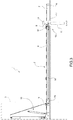
Figure 3 is a side view, with parts removed for clarity, of the pull down bed shown inFigure 1 , in the open position; -
Figure 4 is a side view, with parts removed for clarity, of the pull down bed shown inFigure 1 , in the closed position; -
Figure 5 shows, on an enlarged scale for clarity, a leg and a part of a mechanism for moving the leg of the pull down bed shown inFigure 1 , according to a first embodiment; -
Figure 6 shows, on an enlarged scale for clarity, a leg and a part of a mechanism for moving the leg of the pull down bed shown inFigure 1 , according to a second embodiment; -
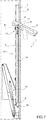
Figure 7 is a side view, with parts removed for clarity, of the pull down bed shown inFigure 1 , in the closed position and with an obstacle preventing the closing of a leg. - The present invention will now be described in detail with reference to the accompanying drawings in order to allow a skilled person to implement it and use it. Various modifications to the described embodiments will be readily apparent to those skilled in the art and the general principles described may be applied to other embodiments and applications without however departing from the protective scope of the present invention as defined in the appended claims. Therefore, the present invention should not be construed as limited to the embodiments described and illustrated herein, but they must be given the broadest protective scope consistent with the principles and features described and claimed herein.
- With reference to
Figure 1 , thenumeral 1 indicates, as a whole, a pull down bed comprising acabinet 3, and abed frame 2 which is connected to thecabinet 3 so as to rotate about a horizontal axis A between a closed position and an open position. - In the closed position shown in
Figure 2 , thebed frame 2 is arranged at least partially inside thecabinet 3 and lies substantially in an approximately vertical reference plane P, whereas in the open position (Figure 1 ), thebed frame 2 is arranged, almost entirely, outside thecabinet 3 in a lowered position in which it lies in a substantially horizontal plane so that it can be used as a bed. - According to the exemplary embodiment shown in the accompanying Figures, the
cabinet 3 may consist of a substantially box-like element, similar to a wardrobe, which is provided with a compartment 4 whose opening 5, in use, is conveniently closed by thebed frame 2 in the closed position. Preferably, thebed frame 2 can be provided with arectangular panel 6, for example fastened thereto at the bottom, which is structured to form a door for closing theopening 5 of the compartment 4 of thecabinet 3. - With reference to the preferred embodiment shown in
Figure 1 , thebed frame 2 can be preferably, but not necessarily, made of metallic material and sized to support one or more side-by-side mattresses. The following description will refer, without thereby losing generality, to abed frame 2 for supporting two coplanar, side-by-side mattresses (not shown). - The
bed frame 2 comprises a preferably rectangular,perimeter frame 7 which has a longitudinal axis C and a supportingstructure 8 which is stably coupled/connected to theperimeter frame 7 and forms the resting base for the mattress (not shown). In the example shown herein, the supportingstructure 8 is formed by a plurality of side-by-side slats transverse to the longitudinal axis C and parallel to each other. It is understood that the present invention is not limited to a supportingstructure 8 formed by slats, but other types of mattress support systems may be provided alternatively or additionally, such as for example wired bed frames or the like. - With reference to the preferred embodiment shown in
Figures 1 ,3 and4 , thebed frame 2 is hinged/pivoted on the opposite side walls or vertical shoulders of thecabinet 3. In the example shown inFigures 3 and4 , thebed frame 2 is provided with tworotation pins 9 which extend in a cantilever manner on opposite sides of thebed frame 2, coaxial with the axis A, and are preferably rotatably engaged in respective openings/seats associated with the side walls of thecabinet 3. - The pull down
bed 1 further preferably comprises ashock absorber assembly 10 which is structured, on the one hand, to slow down the lowering speed of thebed frame 2 during its rotation from the closed position to the open position, and on the other hand, to exert a predetermined return force on thebed frame 2 during the movement between the open position and the closed position, so as to facilitate its rotation and the reaching of its closed position. Theshock absorber assembly 10 is of a known type and, as it is not the object of the present invention, will not be further described herein except to point out that it can comprise one or more shock absorber devices which connect/couple thebed frame 2 to thecabinet 3. - With reference to the preferred embodiment shown in the attached figures, the pull down
bed 1 further comprises at least oneleg 11, preferably twolegs 11, for resting on the ground, each hinged/pivoted on thebed frame 2 so as to be able to rotate about a horizontal axis B, preferably parallel to axis A, between an operating position (Figures 1 ,3 ,5 and6 ) and a rest position (Figure 4 ). Moreover, theleg 11 is hinged at the distal end of thebed frame 2, preferably by means of apin 12, coaxial with the axis B. In the operating position, theleg 11 is approximately transverse to the plane in which thebed frame 2 lies and has its distal end resting on the ground (Figures 1 ,3 ,5 and6 ), whereas in the rest position, theleg 11 is approximately coplanar with the plane in which thebed frame 2 lies. - In the example shown herein, the
leg 11 preferably comprises a substantially rectangular plate optionally, but not necessarily, made of metallic material. Preferably, a PVC base/tip suitable to protect the ground from contact with the resting end of theleg 11 is fitted on the distal end of theleg 11. It is to be understood that the present invention also relates to other embodiments of the leg, for example comprising a structural shape with a cylindrical or rectangular section, and with a rectilinear or non-linear axis. - With reference to the preferred embodiment shown in the accompanying drawings, the pull down
bed 1 further comprises at least onemovement mechanism 13 which is structured so that the rotation of thebed frame 2 between the open position and the closed position causes the rotation of theleg 11 between the operating position and the rest position, respectively, and vice versa. - Preferably, the
movement mechanism 13 is structured so that the movement of theleg 11 between the operating position and the rest position occurs advantageously in synchronization with the rotation of thebed frame 2 between the open position and the closed position. - With reference to the preferred embodiment shown in
Figure 1 , themovement mechanism 13 is conveniently structured to stop the rotation movement of theleg 11 from the operating position to the rest position in response to the rotation of thebed frame 2 from the open position to the closed position, when theleg 11 encounters an obstacle in its path of rotation about the axis B. - In fact, the Applicant has found that this stopping prevents critical conditions from occurring, in particular when a person's limb, for example a hand, is placed along the rotation path of the
leg 11 and remains disadvantageously trapped between the same and thebed frame 2, with evident risks for the person's safety (Figure 7 ). - According to the preferred embodiment shown in
Figures 1 ,3-7 , themovement mechanism 13 comprises at least onecontrol rod 14 which is interposed between thecabinet 3 and arespective leg 11 and is designed to rotate theleg 11 between the operating position and the rest position in response to the rotation of thebed frame 2 between the open position and the closed position, respectively. - The
movement mechanism 13 comprises at least onesafety member 15, which is structured to cooperate with arespective control rod 14, so that the rotation movement imparted by thecontrol rod 14 to theleg 11 about the axis B from the operating position to the rest position, during the rotation of thebed frame 2, is stopped when theleg 11 is subjected to a predetermined resistance force opposite to its rotation movement, which is indicative of the presence of an obstacle along the rotation path of theleg 11. - According to a preferred embodiment shown in the attached figures, the
control rod 14 extends substantially rectilinear along one side of thebed frame 2 and has a first end coupled/connected to thecabinet 3 by means of a hinge or arotation pin 16, and a second end, opposite the first, which is connected by means of thesafety member 15 to theleg 11 in a position eccentric to the axis B. In the example shown inFigure 5 , the second end of thecontrol rod 14 is connected to theleg 11 by means of a hinge orpin 17 arranged eccentrically with respect to the axis B. - The
safety member 15 further comprises at least one device structured to increase, in a controlled manner, the distance between the second free end of thecontrol rod 14 and the hinge orpin 17 of theleg 11, so as to release the rotation movement of theleg 11 from the rotation movement of thebed frame 2 from the open position to the closed position when theleg 11 is hindered in its rotation path. - According to a preferred exemplary embodiment, the
safety member 15 may comprise an extendable element or body, which is structured to extend axially, in a controlled manner, based on the counteracting force exerted by theleg 11 on thecontrol rod 14, when thebed frame 2 rotates from the open position to the closed position. - Preferably, the extendable element or body of the
safety member 15 is structured so as to extend axially when the counteracting force exerted by theleg 11 on the second end of thecontrol rod 14 exceeds a predetermined safety threshold, so as to release, i.e., release mechanically, the rotation movement of theleg 11 from the rotation movement of thebed frame 2. The predetermined safety threshold can be conveniently defined by an operating condition indicative of the presence of an object which hinders the rotation of theleg 11 about the axis B. - According to one embodiment, the extendable element or body of the
safety member 15 can preferably be structured so as to automatically reduce, following an extension, its length to a predetermined idle length when no counteracting force is exerted by theleg 11 on thecontrol rod 14, for example following the removal of the obstacle along the trajectory of theleg 11. - According to a preferred embodiment, the extendable element or body of the
safety member 15 can also be structured so as to maintain the predetermined idle length unchanged when it is subjected to compression, in particular when thecontrol rod 14 rotates theleg 11 from the rest position to the operating position in response to the rotation of thebed frame 2 from the closed position to the open position. - According to a preferred exemplary embodiment shown in the accompanying drawings, the extendable element or body of the
safety member 15 comprises an elastic mechanical member connected between the second end of thecontrol rod 14 and thepin 17 of theleg 11. The elastic mechanical member may advantageously comprise an elastically deformable oblong element, such as for example a spring. The spring may preferably comprise a helical spring coaxial with the longitudinal axis of thecontrol rod 14. - The helical spring can be structured so that its elastic constant is associated with the predetermined safety threshold. The spring can also be structured to have, at rest, the predetermined idle length. Furthermore, the spring can be structured so that its extension is such as to allow the
leg 11 to be released from thebed frame 2 in case of impact of theleg 11 with an obstacle. - The longitudinal elastic constant of the helical spring of the
safety member 15 is preferably sized so that, on the one hand, the helical spring rotates theleg 11 in the absence of interference along the rotation path thereof, and on the other, it extends and keeps theleg 11 in the open position when the latter encounters a resistance during the closing of thebed frame 2. - It is understood that the extendable element or body of the
safety member 15 according to the present invention is not limited to the use of a spring. - For example, according to a different embodiment, the extendable element or body of the
safety member 15 may comprise an axial damping device. Preferably, the axial damping device may be provided with a pair of rectilinear elements mutually coupled in an axially sliding manner with friction, in which one rectilinear element is connected to the second end of thecontrol rod 14, and the other rectilinear element is coupled to thehinge 17 of thebed frame 2. For example, the rectilinear elements may comprise two tubular elements telescopically coupled to each other. According to another example, the rectilinear elements may comprise acylinder 18 provided with a gas-filled inner chamber containing a piston sliding in the chamber, as shown inFigure 6 . - It is understood that the present invention is not limited to the positioning of the
safety member 15 between thecontrol rod 14 and thepin 17, but other embodiments may be provided. For example, according to one such embodiment, thesafety member 15 is made according to any of the variants described above but is installed on the pull downbed 2 in a different position such as, for example, between thecabinet 3 and thecontrol rod 14, with one end at thehinge 16 and the other end directly connected to the end of thecontrol rod 14 opposite theleg 11. - In a further embodiment, moreover, the
safety member 15 could be arranged along thecontrol rod 14, thereby interrupting the seamless extension of thecontrol rod 14. In the latter embodiment, themovement mechanism 13 comprises twocoaxial control rods 14, which are mutually connected through thesafety member 15, the distal ends of which are connected to thepin 16 and thepin 17, respectively. - The pull down
bed 1 may further comprise a motor unit (not shown) for rotating thebed frame 2 about the axis B between the open position and the closed position. The motor unit may comprise an electric motor, a mechanism for transmitting motion from the drive shaft to thebed frame 2, and an electronic circuit for driving the electric motor. - The operation of the pull down
bed 1 can easily be inferred from the above description. - During the opening operation, the
bed frame 2 is rotated about the axis A from its closed position to its open position, whereas during the closing operation, it is rotated from its open position to its closed position. - During the opening operation, the
movement mechanism 13 rotates theleg 11 about the axis B from its rest position to its operating position, whereas, vice versa, during the closing operation, themovement mechanism 13 rotates theleg 11 from its operating position to its rest position. - In particular, as shown in
Figure 7 , during the closing operation, the safety device extends axially when theleg 11 encounters a resistance and consequently thecontrol rod 14 is subjected to traction. The axial extension of the safety device thus enables the leg to be kept in the open position, i.e., rotated outwards even when thebed frame 2 has completed its closing operation. - The pull down bed described above has many advantages. Firstly, the pull down bed can guarantee the user the necessary safety during the operation for closing the bed frame. In particular, the pull down bed described above is not dangerous for a distracted user who accidentally leaves a limb resting between the bed frame and the leg during the operation for closing the bed frame, since the extension of the safety member allows the leg to remain in the open position, rotated outwards, stopping its scissors-like movement, which was known to be dangerous for the user. In other words, the safety member avoids the risk of causing damage to a distracted user who accidentally leaves a limb resting between the bed frame and the leg during the operation for closing the bed frame. The pull down bed is particularly advantageous if it comprises a motor unit suitable for automatically closing the bed frame without any type of automatic control system that can stop the bed frame from closing in the event of resistance to the closing of one of the legs. Moreover, the pull down
bed 1 described above provides a technical solution to guarantee the user the necessary safety during the operation for closing the bed frame, which is simple, inexpensive and easy to install even on devices already on the market.
Claims (10)
- A pull down bed (1) comprising:a cabinet (3),a bed frame (2) which is designed to support a mattress and is hinged to said cabinet (3) so as to be able to rotate about a first axis (A) between a first position, in which said bed frame (2) is arranged substantially vertical, and a second position in which said bed frame (2) is arranged substantially horizontal,at least one leg (11) which is hinged on the bed frame (2) so as to be able to rotate about a second axis (B) between an operating position, in which the free end of the leg (11) abuts against a supporting surface, and a rest position, in which the leg (11) is approximately coplanar with the plane on which the bed frame (2) lies,movement means (13) which comprise at least one control rod (14) structured to rotate said leg (11) between the rest position and the operating position and in response to the rotation of the bed frame (2) between the first and the second positions,said pull down bed (1) being characterized in that said movement means (13) further comprise at least one safety member (15) which is structured to cooperate with a respective control rod (14) so that the rotation imparted by the control rod (14) to said leg (11) about the second axis (B) from the operating position to the rest position, in response to the rotation of the bed frame (2) from the second position to the first position, is stopped when the leg (11) is hindered in its rotation movement about said second axis (B) .
- The bed according to claim 1, wherein said safety member (15) comprises at least one device structured to increase, in a controlled manner, the distance between a free end of the control rod (14) and a connecting element (17) connected to the leg (11).
- The bed according to claim 1 or 2, wherein said safety member (15) comprises an extendable element, which is structured to extend axially, in a controlled manner, based on a counteracting force exerted by the leg (11) on the said control rod (14).
- The bed according to any one of the preceding claims, wherein said safety member (15) is structured so as to extend axially when the counteracting force exerted by the leg (11) on said free end of the control rod (14) exceeds a preestablished safety threshold.
- The bed according to any one of the preceding claims, wherein said safety member (15) is structured so as to automatically reduce, following an extension, its length to a predetermined idle length when no counteracting force is exerted by the leg (11) on the control rod (14).
- The bed according to claim 5, wherein said safety member (15) is structured so as to maintain the predetermined idle length unchanged when the control rod (14) rotates the leg (11) from the rest position to the operating position in response to the rotation of the bed frame (2) from the first position to the second position.
- The bed according to any one of the preceding claims, wherein said safety member (15) comprises an elastic mechanical member.
- The bed according to any one of the preceding claims, wherein said safety member (15) comprises an elastically deformable oblong element.
- The bed according to any one of the preceding claims, wherein said safety member (15) comprises a spring.
- The bed according to any one of the claims 1 to 6, wherein said safety member (15) comprises a pair of rectilinear elements mutually coupled in an axially sliding manner with friction.
Applications Claiming Priority (1)
| Application Number | Priority Date | Filing Date | Title |
|---|---|---|---|
| IT102020000005059A IT202000005059A1 (en) | 2020-03-10 | 2020-03-10 | FOLDABLE BED |
Publications (2)
| Publication Number | Publication Date |
|---|---|
| EP3878317A1 true EP3878317A1 (en) | 2021-09-15 |
| EP3878317B1 EP3878317B1 (en) | 2023-09-06 |
Family
ID=70804954
Family Applications (1)
| Application Number | Title | Priority Date | Filing Date |
|---|---|---|---|
| EP21161812.9A Active EP3878317B1 (en) | 2020-03-10 | 2021-03-10 | Pull down bed |
Country Status (3)
| Country | Link |
|---|---|
| EP (1) | EP3878317B1 (en) |
| ES (1) | ES2963586T3 (en) |
| IT (1) | IT202000005059A1 (en) |
Citations (3)
| Publication number | Priority date | Publication date | Assignee | Title |
|---|---|---|---|---|
| US3805307A (en) * | 1971-06-11 | 1974-04-23 | J Foufounis | Folding bed |
| DE7435265U (en) * | 1973-10-25 | 1975-03-27 | Dryjak A | Murphy bed |
| WO2013190449A1 (en) * | 2012-06-19 | 2013-12-27 | Pessottoreti S.A.S. | Liftable/lowerable bed |
-
2020
- 2020-03-10 IT IT102020000005059A patent/IT202000005059A1/en unknown
-
2021
- 2021-03-10 EP EP21161812.9A patent/EP3878317B1/en active Active
- 2021-03-10 ES ES21161812T patent/ES2963586T3/en active Active
Patent Citations (3)
| Publication number | Priority date | Publication date | Assignee | Title |
|---|---|---|---|---|
| US3805307A (en) * | 1971-06-11 | 1974-04-23 | J Foufounis | Folding bed |
| DE7435265U (en) * | 1973-10-25 | 1975-03-27 | Dryjak A | Murphy bed |
| WO2013190449A1 (en) * | 2012-06-19 | 2013-12-27 | Pessottoreti S.A.S. | Liftable/lowerable bed |
Also Published As
| Publication number | Publication date |
|---|---|
| ES2963586T3 (en) | 2024-04-01 |
| IT202000005059A1 (en) | 2021-09-10 |
| EP3878317B1 (en) | 2023-09-06 |
Similar Documents
| Publication | Publication Date | Title |
|---|---|---|
| RU2500870C2 (en) | Piece of furniture with pushing device for mobile parts of furniture | |
| TWI417067B (en) | Guide rail of drawer | |
| KR102579883B1 (en) | Refrigerator | |
| KR20180089450A (en) | Assembly for moving furniture doors | |
| EP3887632B1 (en) | Furniture hinge for upward-opening cabinet doors | |
| US8079651B2 (en) | Motion control for extension and retraction arrangements | |
| JP2005504605A (en) | Operating table | |
| KR100608687B1 (en) | Refrigerator with basket cushion | |
| US8276857B2 (en) | Extension and retraction arrangement with articulated door | |
| JP5687066B2 (en) | Actuator | |
| EP2108288B1 (en) | Articulated bed with lifting mechanism | |
| EP3878317B1 (en) | Pull down bed | |
| US6752475B2 (en) | Storage apparatus | |
| KR20060006588A (en) | Refrigerator with basket lift | |
| JP6605644B2 (en) | Operation control apparatus and parts assembly including the same | |
| EP2777672B1 (en) | Person support apparatus | |
| AT514056A4 (en) | Arrangement with hinge, linear guide and sensor device | |
| WO2001017400A1 (en) | Rotary actuator; especially for adjustable separate bottoms to beds and beds as well as a construction with such a rotary actuator | |
| KR101855822B1 (en) | storage closet with controlling height | |
| EP2404528A1 (en) | Turning-over sleeping platform | |
| KR102591710B1 (en) | Drawer assembly | |
| KR20100008991A (en) | A door sliding unit for furniture | |
| EP3120730B1 (en) | Assembly formed by a tray, screen support, and a screen | |
| KR100635448B1 (en) | Hinge Device for Kimchi Refrigerator Door | |
| KR102690149B1 (en) | Lift-up system |
Legal Events
| Date | Code | Title | Description |
|---|---|---|---|
| PUAI | Public reference made under article 153(3) epc to a published international application that has entered the european phase |
Free format text: ORIGINAL CODE: 0009012 |
|
| STAA | Information on the status of an ep patent application or granted ep patent |
Free format text: STATUS: THE APPLICATION HAS BEEN PUBLISHED |
|
| AK | Designated contracting states |
Kind code of ref document: A1 Designated state(s): AL AT BE BG CH CY CZ DE DK EE ES FI FR GB GR HR HU IE IS IT LI LT LU LV MC MK MT NL NO PL PT RO RS SE SI SK SM TR |
|
| STAA | Information on the status of an ep patent application or granted ep patent |
Free format text: STATUS: REQUEST FOR EXAMINATION WAS MADE |
|
| 17P | Request for examination filed |
Effective date: 20220311 |
|
| RBV | Designated contracting states (corrected) |
Designated state(s): AL AT BE BG CH CY CZ DE DK EE ES FI FR GB GR HR HU IE IS IT LI LT LU LV MC MK MT NL NO PL PT RO RS SE SI SK SM TR |
|
| GRAP | Despatch of communication of intention to grant a patent |
Free format text: ORIGINAL CODE: EPIDOSNIGR1 |
|
| STAA | Information on the status of an ep patent application or granted ep patent |
Free format text: STATUS: GRANT OF PATENT IS INTENDED |
|
| INTG | Intention to grant announced |
Effective date: 20230323 |
|
| GRAS | Grant fee paid |
Free format text: ORIGINAL CODE: EPIDOSNIGR3 |
|
| GRAA | (expected) grant |
Free format text: ORIGINAL CODE: 0009210 |
|
| STAA | Information on the status of an ep patent application or granted ep patent |
Free format text: STATUS: THE PATENT HAS BEEN GRANTED |
|
| AK | Designated contracting states |
Kind code of ref document: B1 Designated state(s): AL AT BE BG CH CY CZ DE DK EE ES FI FR GB GR HR HU IE IS IT LI LT LU LV MC MK MT NL NO PL PT RO RS SE SI SK SM TR |
|
| REG | Reference to a national code |
Ref country code: GB Ref legal event code: FG4D |
|
| P01 | Opt-out of the competence of the unified patent court (upc) registered |
Effective date: 20230803 |
|
| REG | Reference to a national code |
Ref country code: CH Ref legal event code: EP |
|
| REG | Reference to a national code |
Ref country code: IE Ref legal event code: FG4D |
|
| REG | Reference to a national code |
Ref country code: DE Ref legal event code: R096 Ref document number: 602021004814 Country of ref document: DE |
|
| REG | Reference to a national code |
Ref country code: LT Ref legal event code: MG9D |
|
| REG | Reference to a national code |
Ref country code: NL Ref legal event code: MP Effective date: 20230906 |
|
| PG25 | Lapsed in a contracting state [announced via postgrant information from national office to epo] |
Ref country code: GR Free format text: LAPSE BECAUSE OF FAILURE TO SUBMIT A TRANSLATION OF THE DESCRIPTION OR TO PAY THE FEE WITHIN THE PRESCRIBED TIME-LIMIT Effective date: 20231207 |
|
| PG25 | Lapsed in a contracting state [announced via postgrant information from national office to epo] |
Ref country code: SE Free format text: LAPSE BECAUSE OF FAILURE TO SUBMIT A TRANSLATION OF THE DESCRIPTION OR TO PAY THE FEE WITHIN THE PRESCRIBED TIME-LIMIT Effective date: 20230906 Ref country code: RS Free format text: LAPSE BECAUSE OF FAILURE TO SUBMIT A TRANSLATION OF THE DESCRIPTION OR TO PAY THE FEE WITHIN THE PRESCRIBED TIME-LIMIT Effective date: 20230906 Ref country code: NO Free format text: LAPSE BECAUSE OF FAILURE TO SUBMIT A TRANSLATION OF THE DESCRIPTION OR TO PAY THE FEE WITHIN THE PRESCRIBED TIME-LIMIT Effective date: 20231206 Ref country code: LV Free format text: LAPSE BECAUSE OF FAILURE TO SUBMIT A TRANSLATION OF THE DESCRIPTION OR TO PAY THE FEE WITHIN THE PRESCRIBED TIME-LIMIT Effective date: 20230906 Ref country code: LT Free format text: LAPSE BECAUSE OF FAILURE TO SUBMIT A TRANSLATION OF THE DESCRIPTION OR TO PAY THE FEE WITHIN THE PRESCRIBED TIME-LIMIT Effective date: 20230906 Ref country code: HR Free format text: LAPSE BECAUSE OF FAILURE TO SUBMIT A TRANSLATION OF THE DESCRIPTION OR TO PAY THE FEE WITHIN THE PRESCRIBED TIME-LIMIT Effective date: 20230906 Ref country code: GR Free format text: LAPSE BECAUSE OF FAILURE TO SUBMIT A TRANSLATION OF THE DESCRIPTION OR TO PAY THE FEE WITHIN THE PRESCRIBED TIME-LIMIT Effective date: 20231207 Ref country code: FI Free format text: LAPSE BECAUSE OF FAILURE TO SUBMIT A TRANSLATION OF THE DESCRIPTION OR TO PAY THE FEE WITHIN THE PRESCRIBED TIME-LIMIT Effective date: 20230906 |
|
| REG | Reference to a national code |
Ref country code: AT Ref legal event code: MK05 Ref document number: 1607325 Country of ref document: AT Kind code of ref document: T Effective date: 20230906 |
|
| PG25 | Lapsed in a contracting state [announced via postgrant information from national office to epo] |
Ref country code: NL Free format text: LAPSE BECAUSE OF FAILURE TO SUBMIT A TRANSLATION OF THE DESCRIPTION OR TO PAY THE FEE WITHIN THE PRESCRIBED TIME-LIMIT Effective date: 20230906 |
|
| REG | Reference to a national code |
Ref country code: ES Ref legal event code: FG2A Ref document number: 2963586 Country of ref document: ES Kind code of ref document: T3 Effective date: 20240401 |
|
| PG25 | Lapsed in a contracting state [announced via postgrant information from national office to epo] |
Ref country code: IS Free format text: LAPSE BECAUSE OF FAILURE TO SUBMIT A TRANSLATION OF THE DESCRIPTION OR TO PAY THE FEE WITHIN THE PRESCRIBED TIME-LIMIT Effective date: 20240106 |
|
| PG25 | Lapsed in a contracting state [announced via postgrant information from national office to epo] |
Ref country code: AT Free format text: LAPSE BECAUSE OF FAILURE TO SUBMIT A TRANSLATION OF THE DESCRIPTION OR TO PAY THE FEE WITHIN THE PRESCRIBED TIME-LIMIT Effective date: 20230906 |
|
| PG25 | Lapsed in a contracting state [announced via postgrant information from national office to epo] |
Ref country code: SM Free format text: LAPSE BECAUSE OF FAILURE TO SUBMIT A TRANSLATION OF THE DESCRIPTION OR TO PAY THE FEE WITHIN THE PRESCRIBED TIME-LIMIT Effective date: 20230906 Ref country code: RO Free format text: LAPSE BECAUSE OF FAILURE TO SUBMIT A TRANSLATION OF THE DESCRIPTION OR TO PAY THE FEE WITHIN THE PRESCRIBED TIME-LIMIT Effective date: 20230906 Ref country code: IS Free format text: LAPSE BECAUSE OF FAILURE TO SUBMIT A TRANSLATION OF THE DESCRIPTION OR TO PAY THE FEE WITHIN THE PRESCRIBED TIME-LIMIT Effective date: 20240106 Ref country code: EE Free format text: LAPSE BECAUSE OF FAILURE TO SUBMIT A TRANSLATION OF THE DESCRIPTION OR TO PAY THE FEE WITHIN THE PRESCRIBED TIME-LIMIT Effective date: 20230906 Ref country code: CZ Free format text: LAPSE BECAUSE OF FAILURE TO SUBMIT A TRANSLATION OF THE DESCRIPTION OR TO PAY THE FEE WITHIN THE PRESCRIBED TIME-LIMIT Effective date: 20230906 Ref country code: AT Free format text: LAPSE BECAUSE OF FAILURE TO SUBMIT A TRANSLATION OF THE DESCRIPTION OR TO PAY THE FEE WITHIN THE PRESCRIBED TIME-LIMIT Effective date: 20230906 Ref country code: SK Free format text: LAPSE BECAUSE OF FAILURE TO SUBMIT A TRANSLATION OF THE DESCRIPTION OR TO PAY THE FEE WITHIN THE PRESCRIBED TIME-LIMIT Effective date: 20230906 Ref country code: PT Free format text: LAPSE BECAUSE OF FAILURE TO SUBMIT A TRANSLATION OF THE DESCRIPTION OR TO PAY THE FEE WITHIN THE PRESCRIBED TIME-LIMIT Effective date: 20240108 |
|
| PG25 | Lapsed in a contracting state [announced via postgrant information from national office to epo] |
Ref country code: PL Free format text: LAPSE BECAUSE OF FAILURE TO SUBMIT A TRANSLATION OF THE DESCRIPTION OR TO PAY THE FEE WITHIN THE PRESCRIBED TIME-LIMIT Effective date: 20230906 Ref country code: IT Free format text: LAPSE BECAUSE OF FAILURE TO SUBMIT A TRANSLATION OF THE DESCRIPTION OR TO PAY THE FEE WITHIN THE PRESCRIBED TIME-LIMIT Effective date: 20230906 |
|
| REG | Reference to a national code |
Ref country code: DE Ref legal event code: R097 Ref document number: 602021004814 Country of ref document: DE |
|
| PG25 | Lapsed in a contracting state [announced via postgrant information from national office to epo] |
Ref country code: DK Free format text: LAPSE BECAUSE OF FAILURE TO SUBMIT A TRANSLATION OF THE DESCRIPTION OR TO PAY THE FEE WITHIN THE PRESCRIBED TIME-LIMIT Effective date: 20230906 |
|
| PLBE | No opposition filed within time limit |
Free format text: ORIGINAL CODE: 0009261 |
|
| STAA | Information on the status of an ep patent application or granted ep patent |
Free format text: STATUS: NO OPPOSITION FILED WITHIN TIME LIMIT |
|
| PG25 | Lapsed in a contracting state [announced via postgrant information from national office to epo] |
Ref country code: DK Free format text: LAPSE BECAUSE OF FAILURE TO SUBMIT A TRANSLATION OF THE DESCRIPTION OR TO PAY THE FEE WITHIN THE PRESCRIBED TIME-LIMIT Effective date: 20230906 Ref country code: SI Free format text: LAPSE BECAUSE OF FAILURE TO SUBMIT A TRANSLATION OF THE DESCRIPTION OR TO PAY THE FEE WITHIN THE PRESCRIBED TIME-LIMIT Effective date: 20230906 |
|
| 26N | No opposition filed |
Effective date: 20240607 |
|
| REG | Reference to a national code |
Ref country code: CH Ref legal event code: PL |
|
| PG25 | Lapsed in a contracting state [announced via postgrant information from national office to epo] |
Ref country code: BG Free format text: LAPSE BECAUSE OF FAILURE TO SUBMIT A TRANSLATION OF THE DESCRIPTION OR TO PAY THE FEE WITHIN THE PRESCRIBED TIME-LIMIT Effective date: 20230906 |
|
| PG25 | Lapsed in a contracting state [announced via postgrant information from national office to epo] |
Ref country code: LU Free format text: LAPSE BECAUSE OF NON-PAYMENT OF DUE FEES Effective date: 20240310 |
|
| PG25 | Lapsed in a contracting state [announced via postgrant information from national office to epo] |
Ref country code: MC Free format text: LAPSE BECAUSE OF FAILURE TO SUBMIT A TRANSLATION OF THE DESCRIPTION OR TO PAY THE FEE WITHIN THE PRESCRIBED TIME-LIMIT Effective date: 20230906 |
|
| PG25 | Lapsed in a contracting state [announced via postgrant information from national office to epo] |
Ref country code: MC Free format text: LAPSE BECAUSE OF FAILURE TO SUBMIT A TRANSLATION OF THE DESCRIPTION OR TO PAY THE FEE WITHIN THE PRESCRIBED TIME-LIMIT Effective date: 20230906 Ref country code: LU Free format text: LAPSE BECAUSE OF NON-PAYMENT OF DUE FEES Effective date: 20240310 Ref country code: BG Free format text: LAPSE BECAUSE OF FAILURE TO SUBMIT A TRANSLATION OF THE DESCRIPTION OR TO PAY THE FEE WITHIN THE PRESCRIBED TIME-LIMIT Effective date: 20230906 |
|
| REG | Reference to a national code |
Ref country code: BE Ref legal event code: MM Effective date: 20240331 |
|
| PG25 | Lapsed in a contracting state [announced via postgrant information from national office to epo] |
Ref country code: BE Free format text: LAPSE BECAUSE OF NON-PAYMENT OF DUE FEES Effective date: 20240331 |
|
| PG25 | Lapsed in a contracting state [announced via postgrant information from national office to epo] |
Ref country code: IE Free format text: LAPSE BECAUSE OF NON-PAYMENT OF DUE FEES Effective date: 20240310 |
|
| PG25 | Lapsed in a contracting state [announced via postgrant information from national office to epo] |
Ref country code: IE Free format text: LAPSE BECAUSE OF NON-PAYMENT OF DUE FEES Effective date: 20240310 Ref country code: BE Free format text: LAPSE BECAUSE OF NON-PAYMENT OF DUE FEES Effective date: 20240331 Ref country code: CH Free format text: LAPSE BECAUSE OF NON-PAYMENT OF DUE FEES Effective date: 20240331 |
|
| PGFP | Annual fee paid to national office [announced via postgrant information from national office to epo] |
Ref country code: ES Payment date: 20250417 Year of fee payment: 5 |
|
| PG25 | Lapsed in a contracting state [announced via postgrant information from national office to epo] |
Ref country code: CY Free format text: LAPSE BECAUSE OF FAILURE TO SUBMIT A TRANSLATION OF THE DESCRIPTION OR TO PAY THE FEE WITHIN THE PRESCRIBED TIME-LIMIT; INVALID AB INITIO Effective date: 20210310 |
|
| PG25 | Lapsed in a contracting state [announced via postgrant information from national office to epo] |
Ref country code: HU Free format text: LAPSE BECAUSE OF FAILURE TO SUBMIT A TRANSLATION OF THE DESCRIPTION OR TO PAY THE FEE WITHIN THE PRESCRIBED TIME-LIMIT; INVALID AB INITIO Effective date: 20210310 |
|
| PG25 | Lapsed in a contracting state [announced via postgrant information from national office to epo] |
Ref country code: TR Free format text: LAPSE BECAUSE OF FAILURE TO SUBMIT A TRANSLATION OF THE DESCRIPTION OR TO PAY THE FEE WITHIN THE PRESCRIBED TIME-LIMIT Effective date: 20230906 |
|
| PGFP | Annual fee paid to national office [announced via postgrant information from national office to epo] |
Ref country code: GB Payment date: 20260304 Year of fee payment: 6 |
|
| PGFP | Annual fee paid to national office [announced via postgrant information from national office to epo] |
Ref country code: DE Payment date: 20260320 Year of fee payment: 6 |
|
| PGFP | Annual fee paid to national office [announced via postgrant information from national office to epo] |
Ref country code: FR Payment date: 20260323 Year of fee payment: 6 |