EP3878121B1 - Methods and apparatus for harq in wireless networks - Google Patents
Methods and apparatus for harq in wireless networks Download PDFInfo
- Publication number
- EP3878121B1 EP3878121B1 EP19809293.4A EP19809293A EP3878121B1 EP 3878121 B1 EP3878121 B1 EP 3878121B1 EP 19809293 A EP19809293 A EP 19809293A EP 3878121 B1 EP3878121 B1 EP 3878121B1
- Authority
- EP
- European Patent Office
- Prior art keywords
- harq
- transmission
- ppdu
- sta
- stas
- Prior art date
- Legal status (The legal status is an assumption and is not a legal conclusion. Google has not performed a legal analysis and makes no representation as to the accuracy of the status listed.)
- Active
Links
Images




Classifications
-
- H—ELECTRICITY
- H04—ELECTRIC COMMUNICATION TECHNIQUE
- H04L—TRANSMISSION OF DIGITAL INFORMATION, e.g. TELEGRAPHIC COMMUNICATION
- H04L1/00—Arrangements for detecting or preventing errors in the information received
- H04L1/12—Arrangements for detecting or preventing errors in the information received by using return channel
- H04L1/16—Arrangements for detecting or preventing errors in the information received by using return channel in which the return channel carries supervisory signals, e.g. repetition request signals
- H04L1/18—Automatic repetition systems, e.g. Van Duuren systems
- H04L1/1812—Hybrid protocols; Hybrid automatic repeat request [HARQ]
- H04L1/1819—Hybrid protocols; Hybrid automatic repeat request [HARQ] with retransmission of additional or different redundancy
-
- H—ELECTRICITY
- H04—ELECTRIC COMMUNICATION TECHNIQUE
- H04L—TRANSMISSION OF DIGITAL INFORMATION, e.g. TELEGRAPHIC COMMUNICATION
- H04L1/00—Arrangements for detecting or preventing errors in the information received
- H04L1/12—Arrangements for detecting or preventing errors in the information received by using return channel
- H04L1/16—Arrangements for detecting or preventing errors in the information received by using return channel in which the return channel carries supervisory signals, e.g. repetition request signals
- H04L1/1607—Details of the supervisory signal
- H04L1/1614—Details of the supervisory signal using bitmaps
-
- H—ELECTRICITY
- H04—ELECTRIC COMMUNICATION TECHNIQUE
- H04L—TRANSMISSION OF DIGITAL INFORMATION, e.g. TELEGRAPHIC COMMUNICATION
- H04L1/00—Arrangements for detecting or preventing errors in the information received
- H04L1/12—Arrangements for detecting or preventing errors in the information received by using return channel
- H04L1/16—Arrangements for detecting or preventing errors in the information received by using return channel in which the return channel carries supervisory signals, e.g. repetition request signals
- H04L1/1607—Details of the supervisory signal
- H04L1/1621—Group acknowledgement, i.e. the acknowledgement message defining a range of identifiers, e.g. of sequence numbers
-
- H—ELECTRICITY
- H04—ELECTRIC COMMUNICATION TECHNIQUE
- H04L—TRANSMISSION OF DIGITAL INFORMATION, e.g. TELEGRAPHIC COMMUNICATION
- H04L1/00—Arrangements for detecting or preventing errors in the information received
- H04L1/12—Arrangements for detecting or preventing errors in the information received by using return channel
- H04L1/16—Arrangements for detecting or preventing errors in the information received by using return channel in which the return channel carries supervisory signals, e.g. repetition request signals
- H04L1/1607—Details of the supervisory signal
- H04L1/1685—Details of the supervisory signal the supervisory signal being transmitted in response to a specific request, e.g. to a polling signal
-
- H—ELECTRICITY
- H04—ELECTRIC COMMUNICATION TECHNIQUE
- H04L—TRANSMISSION OF DIGITAL INFORMATION, e.g. TELEGRAPHIC COMMUNICATION
- H04L1/00—Arrangements for detecting or preventing errors in the information received
- H04L1/12—Arrangements for detecting or preventing errors in the information received by using return channel
- H04L1/16—Arrangements for detecting or preventing errors in the information received by using return channel in which the return channel carries supervisory signals, e.g. repetition request signals
- H04L1/18—Automatic repetition systems, e.g. Van Duuren systems
- H04L1/1822—Automatic repetition systems, e.g. Van Duuren systems involving configuration of automatic repeat request [ARQ] with parallel processes
-
- H—ELECTRICITY
- H04—ELECTRIC COMMUNICATION TECHNIQUE
- H04L—TRANSMISSION OF DIGITAL INFORMATION, e.g. TELEGRAPHIC COMMUNICATION
- H04L1/00—Arrangements for detecting or preventing errors in the information received
- H04L1/12—Arrangements for detecting or preventing errors in the information received by using return channel
- H04L1/16—Arrangements for detecting or preventing errors in the information received by using return channel in which the return channel carries supervisory signals, e.g. repetition request signals
- H04L1/18—Automatic repetition systems, e.g. Van Duuren systems
- H04L1/1829—Arrangements specially adapted for the receiver end
- H04L1/1864—ARQ related signaling
-
- H—ELECTRICITY
- H04—ELECTRIC COMMUNICATION TECHNIQUE
- H04L—TRANSMISSION OF DIGITAL INFORMATION, e.g. TELEGRAPHIC COMMUNICATION
- H04L1/00—Arrangements for detecting or preventing errors in the information received
- H04L1/12—Arrangements for detecting or preventing errors in the information received by using return channel
- H04L1/16—Arrangements for detecting or preventing errors in the information received by using return channel in which the return channel carries supervisory signals, e.g. repetition request signals
- H04L1/18—Automatic repetition systems, e.g. Van Duuren systems
- H04L1/1867—Arrangements specially adapted for the transmitter end
- H04L1/1896—ARQ related signaling
-
- H—ELECTRICITY
- H04—ELECTRIC COMMUNICATION TECHNIQUE
- H04L—TRANSMISSION OF DIGITAL INFORMATION, e.g. TELEGRAPHIC COMMUNICATION
- H04L1/00—Arrangements for detecting or preventing errors in the information received
- H04L2001/0092—Error control systems characterised by the topology of the transmission link
- H04L2001/0093—Point-to-multipoint
Definitions
- a WLAN [1] in Infrastructure Basic Service Set (BSS) mode has an Access Point (AP) for the BSS and one or more stations (STAs) associated with the AP.
- the AP typically interfaces with a Distribution System (DS) or other type of wired/wireless network that carries traffic in and out of the BSS.
- Traffic to STAs that originates from outside the BSS arrives through the AP and is delivered to the STAs.
- Traffic originating from STAs to destinations outside the BSS is sent to the AP to be delivered to the respective destinations.
- Traffic between STAs within the BSS may also be sent through the AP where the source STA sends traffic to the AP and the AP delivers the traffic to the destination STA.
- Such traffic between STAs within a BSS is essentially peer-to-peer traffic.
- Such peer-to-peer traffic may also be sent directly between the source and destination STAs with a direct link setup (DLS) using an 802.11e DLS or an 802.11z tunnelled DLS (TDLS).
- DLS direct link setup
- TDLS 802.11z tunnelled DLS
- IBSS Independent BSS
- a WLAN using an Independent BSS (IBSS) mode has no AP. Rather, the STAs communicate directly with each other in a peer-to-peer type mode of communication. This mode of communication is referred to as an "ad-hoc" mode of communication.
- the AP may transmit a beacon on a fixed channel, usually the primary channel.
- This channel may be 20 MHz wide, and is the operating channel of the BSS.
- This channel is also used by the STAs to establish a connection with the AP.
- the fundamental channel access mechanism in an 802.11 system is Carrier Sense Multiple Access with Collision Avoidance (CSMA/CA).
- CSMA/CA Carrier Sense Multiple Access with Collision Avoidance
- every STA, including the AP will sense the primary channel. If the channel is detected to be busy, the STA backs off. Hence only one STA may transmit at any given time in a given BSS.
- High Throughput (HT) STAs may also use a 40 MHz wide channel for communication. This is achieved by combining the primary 20 MHz channel, with an adjacent 20 MHz channel to form a 40 MHz wide contiguous channel.
- VHT STAs may support 20MHz, 40 MHz, 80 MHz, and 160 MHz wide channels.
- the 40 MHz and 80 MHz channels are formed by combining contiguous 20 MHz channels similarly to the manner described above in connection with 802.11n.
- a 160 MHz channel may be formed either by combining 8 contiguous 20 MHz channels, or by combining two non-contiguous 80 MHz channels.
- This type of configuration may also be referred to as an 80+80 configuration.
- the data after channel encoding, is passed through a segment parser that divides it into two streams. IFFT and time domain processing are performed on each stream separately. The streams are then mapped onto the two 80 MHz channels, and the data is transmitted. At the receiver, this mechanism is reversed, and the combined data is sent to the MAC.
- Sub 1 GHz modes of operation are supported by 802.11af [3], and 802.11ah [4]. For these specifications, the channel operating bandwidths and carriers are reduced relative to those used in 802.11n [1], and 802.11ac [2].
- 802.11af supports 5 MHz, 10 MHz and 20 MHz bandwidths in the TV White Space (TVWS) spectrum
- 802.11ah supports 1 MHz, 2 MHz, 4 MHz, 8 MHz, and 16 MHz bandwidths using non-TVWS spectrum.
- a possible use case for 802.11ah is support for Meter Type Control (MTC) devices in a macro coverage area. MTC devices may have limited capabilities including only support for limited bandwidths, but also include a requirement for a very long battery life.
- MTC Meter Type Control
- WLAN systems that support multiple channels and channel widths, such as 802.11n, 802.11ac, 802.11af, and 802.11ah, include a channel that is designated as the primary channel.
- the primary channel may, but does not necessarily, have a bandwidth equal to the largest common operating bandwidth supported by all STAs in the BSS. The bandwidth of the primary channel is therefore limited by the STA operating in the particular BSS that supports the smallest bandwidth operating mode.
- the primary channel may be 1 MHz wide if there are STAs (e.g.
- the available frequency bands that may be used by 802.11ah are from 902 MHz to 928 MHz. In Korea, it is from 917.5 MHz to 923.5 MHz; and in Japan, it is from 916.5 MHz to 927.5 MHz.
- the total bandwidth available for 802.11ah is 6 MHz to 26 MHz depending on the country.
- TGax there is a strong likelihood that the traffic for a variety of applications may comprise short packets.
- network applications that generate short packets, such as: Virtual office applications; TPC ACK (Transmit Control Power Acknowledgement); Video streaming ACK; Device/Controller applications (mice, keyboards, game controls, etc.); Access applications (Probe request/response); Network selection (probe requests and ANQP (Access Network Query Protocol)); and Network management applications (control frames).
- 802.11ax may implement UL and DL OFDMA and/or UL and DL MU-MIMO. Hence, designing and defining a mechanism for multiplexing UL random access for different purposes may be addressed in the standard.
- Section 27.5.6.4 (NPD feedback report types) of [7] describes the Null Data Packet (NDP) feedback design in 802.11ax.
- the feedback uses a punctured High-Efficiency Long Training Field (HE-LTF) to signal information and, thus, does not require a receiver to perform channel estimation.
- HE-LTF High-Efficiency Long Training Field
- 12 OFDM tones are used with half on and half off.
- Hybrid Automatic Repeat reQuest has become an essential transmission error control technique in wireless communication networks, which relies on a combination of error correction codes and retransmissions.
- HARQ has been adopted in wireless communications standards such as 3GPP UMTS, LTE, and IEEE 802.16 WiMax.
- HARQ combining schemes There are two popular types of HARQ combining schemes in the technical literature: Chase Combining (CC) HARQ and Incremental Redundancy (IR) HARQ.
- CC Chase Combining
- IR Incremental Redundancy
- each retransmission contains the same data and parity bits.
- a receiver uses Maximum Ratio Combining (MRC) to combine the received packet with previous transmission(s).
- MRC Maximum Ratio Combining
- Chase Combining can be regarded as repetition coding, in which each retransmission increases the Eb/No (Energy per bit, Eb, to noise spectral power density, No, ratio) at the receiver.
- each retransmission uses a different set of coded bits (different redundancy versions generated by puncturing the encoder output). For turbo code, this means different systematic and parity bits. At each retransmission, the receiver gains extra information.
- coded bits different redundancy versions generated by puncturing the encoder output.
- turbo code this means different systematic and parity bits.
- the receiver gains extra information.
- IR HARQ e.g., a retransmission contains only parity bits or it is self-decodable.
- HARQ schemes can be categorized as either synchronous or asynchronous, with the retransmissions in each case being either adaptive or non-adaptive.
- synchronous HARQ retransmissions for each process occur at predefined times relative to the initial transmission.
- asynchronous HARQ retransmissions can occur at any time relative to the initial transmission.
- explicit signaling is required to indicate HARQ process ID to ensure that the receiver can correctly associate each retransmission with the corresponding previous transmission.
- the HARQ entity is located in the MAC layer, which is responsible for the transmit and receive HARQ operations.
- the transmit HARQ operation includes transmission and retransmission of transport blocks, and reception and processing of ACK/NACK signaling.
- the receive HARQ operation includes reception of transport blocks, combining of the received data, and generation of ACK/NACK signaling based on decoding results.
- up to eight HARQ processes in parallel are used to support multiprocess 'Stop-And-Wait' (SAW) HARQ operation. Therefore, multiprocess HARQ interlaces several independent SAW processes in time so that all the transmission resources can be used by one of the processes. Each HARQ process is responsible for a separate SAW operation and manages a separate buffer.
- asynchronous adaptive HARQ is used in the downlink and synchronous (either adaptive or non-adaptive) HARQ is used in the uplink.
- 3GPP NR New Radio
- the following HARQ features are supported: Multiple HARQ processes; Dynamic and semi-static HARQ ACK codebook; CBG level HARQ retransmission; Asynchronous and adaptive HARQ; and Flexible timing between data transmission and HARQ ACK feedback.
- HARQ feedback may be transmitted in an unlicensed band.
- NR-U considers mechanisms to support flexible triggering and multiplexing of HARQ feedback for one or more DL HARQ processes. The following techniques are deemed beneficial for NR-U transmissions by 3GPP:
- Document US 2016/380727 A1 discloses a DL multi-user MU transmission in a IEEE 802.11 system using HARQ-based retransmission triggered by Block Ack.
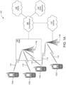
- the communications system 100 may include wireless transmit/receive units (WTRUs) 102a, 102b, 102c, 102d, a RAN 104/113, a CN 106/115, a public switched telephone network (PSTN) 108, the Internet 110, and other networks 112, though it will be appreciated that the disclosed embodiments contemplate any number of WTRUs, base stations, networks, and/or network elements.
- WTRUs 102a, 102b, 102c, 102d may be any type of device configured to operate and/or communicate in a wireless environment.
- the WTRUs 102a, 102b, 102c, 102d may be configured to transmit and/or receive wireless signals and may include a user equipment (UE), a mobile station, a fixed or mobile subscriber unit, a subscription-based unit, a pager, a cellular telephone, a personal digital assistant (PDA), a smartphone, a laptop, a netbook, a personal computer, a wireless sensor, a hotspot or Mi-Fi device, an Internet of Things (IoT) device, a watch or other wearable, a head-mounted display (HMD), a vehicle, a drone, a medical device and applications (e.g., remote surgery), an industrial device and applications (e.g., a robot and/or other wireless devices operating in an industrial and/or an automated processing chain contexts), a consumer electronics device, a device operating on commercial and/or industrial wireless networks, and the like.
- UE user equipment
- PDA personal digital assistant
- smartphone a laptop
- a netbook a personal computer
- the communications system 100 may also include a base station 114a and/or a base station 114b.
- Each of the base stations 114a, 114b may be any type of device configured to wirelessly interface with at least one of the WTRUs 102a, 102b, 102c, 102d to facilitate access to one or more communication networks, such as the CN 106/115, the Internet 110, and/or the other networks 112.
- the base station 114a may be part of the RAN 104/113, which may also include other base stations and/or network elements (not shown), such as a base station controller (BSC), a radio network controller (RNC), relay nodes, etc.
- BSC base station controller
- RNC radio network controller
- the base station 114a and/or the base station 114b may be configured to transmit and/or receive wireless signals on one or more carrier frequencies, which may be referred to as a cell (not shown). These frequencies may be in licensed spectrum, unlicensed spectrum, or a combination of licensed and unlicensed spectrum.
- a cell may provide coverage for a wireless service to a specific geographical area that may be relatively fixed or that may change over time.
- the cell may further be divided into cell sectors. For example, the cell associated with the base station 114a may be divided into three sectors.
- the communications system 100 may be a multiple access system and may employ one or more channel access schemes, such as CDMA, TDMA, FDMA, OFDMA, SC-FDMA, and the like.
- the base station 114a in the RAN 104/113 and the WTRUs 102a, 102b, 102c may implement a radio technology such as Universal Mobile Telecommunications System (UMTS) Terrestrial Radio Access (UTRA), which may establish the air interface 115/116/117 using wideband CDMA (WCDMA).
- WCDMA may include communication protocols such as High-Speed Packet Access (HSPA) and/or Evolved HSPA (HSPA+).
- HSPA may include High-Speed Downlink (DL) Packet Access (HSDPA) and/or High-Speed UL Packet Access (HSUPA).
- the base station 114a and the WTRUs 102a, 102b, 102c may implement a radio technology such as Evolved UMTS Terrestrial Radio Access (E-UTRA), which may establish the air interface 116 using Long Term Evolution (LTE) and/or LTE-Advanced (LTE-A) and/or LTE-Advanced Pro (LTE-A Pro).
- E-UTRA Evolved UMTS Terrestrial Radio Access
- LTE Long Term Evolution
- LTE-A LTE-Advanced
- LTE-A Pro LTE-Advanced Pro
- the base station 114a and the WTRUs 102a, 102b, 102c may implement a radio technology such as NR Radio Access, which may establish the air interface 116 using New Radio (NR).
- a radio technology such as NR Radio Access, which may establish the air interface 116 using New Radio (NR).
- the base station 114a and the WTRUs 102a, 102b, 102c may implement multiple radio access technologies.
- the base station 114a and the WTRUs 102a, 102b, 102c may implement LTE radio access and NR radio access together, for instance using dual connectivity (DC) principles.
- DC dual connectivity
- the air interface utilized by WTRUs 102a, 102b, 102c may be characterized by multiple types of radio access technologies and/or transmissions sent to/from multiple types of base stations (e.g., a eNB and a gNB).
- the base station 114b in FIG. 1A may be a wireless router, Home Node B, Home eNode B, or access point, for example, and may utilize any suitable RAT for facilitating wireless connectivity in a localized area, such as a place of business, a home, a vehicle, a campus, an industrial facility, an air corridor (e.g., for use by drones), a roadway, and the like.
- the base station 114b and the WTRUs 102c, 102d may implement a radio technology such as IEEE 802.11 to establish a wireless local area network (WLAN).
- WLAN wireless local area network
- the base station 114b and the WTRUs 102c, 102d may implement a radio technology such as IEEE 802.15 to establish a wireless personal area network (WPAN).
- the base station 114b and the WTRUs 102c, 102d may utilize a cellular-based RAT (e.g., WCDMA, CDMA2000, GSM, LTE, LTE-A, LTE-A Pro, NR etc.) to establish a picocell or femtocell.
- the base station 114b may have a direct connection to the Internet 110.
- the base station 114b may not be required to access the Internet 110 via the CN 106/115.
- the RAN 104/113 may be in communication with the CN 106/115, which may be any type of network configured to provide voice, data, applications, and/or voice over internet protocol (VoIP) services to one or more of the WTRUs 102a, 102b, 102c, 102d.
- the data may have varying quality of service (QoS) requirements, such as differing throughput requirements, latency requirements, error tolerance requirements, reliability requirements, data throughput requirements, mobility requirements, and the like.
- QoS quality of service
- the CN 106/115 may provide call control, billing services, mobile location-based services, pre-paid calling, Internet connectivity, video distribution, etc., and/or perform high-level security functions, such as user authentication.
- the RAN 104/113 and/or the CN 106/115 may be in direct or indirect communication with other RANs that employ the same RAT as the RAN 104/113 or a different RAT.
- the CN 106/115 may also be in communication with another RAN (not shown) employing a GSM, UMTS, CDMA 2000, WiMAX, E-UTRA, or WiFi radio technology.
- the CN 106/115 may also serve as a gateway for the WTRUs 102a, 102b, 102c, 102d to access the PSTN 108, the Internet 110, and/or the other networks 112.
- the PSTN 108 may include circuit-switched telephone networks that provide plain old telephone service (POTS).
- POTS plain old telephone service
- the Internet 110 may include a global system of interconnected computer networks and devices that use common communication protocols, such as the transmission control protocol (TCP), user datagram protocol (UDP) and/or the internet protocol (IP) in the TCP/IP internet protocol suite.
- the networks 112 may include wired and/or wireless communications networks owned and/or operated by other service providers.
- the networks 112 may include another CN connected to one or more RANs, which may employ the same RAT as the RAN 104/113 or a different RAT.
- the WTRUs 102a, 102b, 102c, 102d in the communications system 100 may include multi-mode capabilities (e.g., the WTRUs 102a, 102b, 102c, 102d may include multiple transceivers for communicating with different wireless networks over different wireless links).
- the WTRU 102c shown in FIG. 1A may be configured to communicate with the base station 114a, which may employ a cellular-based radio technology, and with the base station 114b, which may employ an IEEE 802 radio technology.
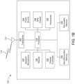
- FIG. 1B is a system diagram illustrating an example WTRU 102.
- the WTRU 102 may include a processor 118, a transceiver 120, a transmit/receive element 122, a speaker/microphone 124, a keypad 126, a display/touchpad 128, non-removable memory 130, removable memory 132, a power source 134, a global positioning system (GPS) chipset 136, and/or other peripherals 138, among others.
- GPS global positioning system
- the processor 118 may be a general purpose processor, a special purpose processor, a conventional processor, a digital signal processor (DSP), a plurality of microprocessors, one or more microprocessors in association with a DSP core, a controller, a microcontroller, Application Specific Integrated Circuits (ASICs), Field Programmable Gate Arrays (FPGAs) circuits, any other type of integrated circuit (IC), a state machine, and the like.
- the processor 118 may perform signal coding, data processing, power control, input/output processing, and/or any other functionality that enables the WTRU 102 to operate in a wireless environment.
- the processor 118 may be coupled to the transceiver 120, which may be coupled to the transmit/receive element 122. While FIG. 1B depicts the processor 118 and the transceiver 120 as separate components, it will be appreciated that the processor 118 and the transceiver 120 may be integrated together in an electronic package or chip.
- the WTRU 102 may include any number of transmit/receive elements 122. More specifically, the WTRU 102 may employ MIMO technology. Thus, in one embodiment, the WTRU 102 may include two or more transmit/receive elements 122 (e.g., multiple antennas) for transmitting and receiving wireless signals over the air interface 116.
- the processor 118 of the WTRU 102 may be coupled to, and may receive user input data from, the speaker/microphone 124, the keypad 126, and/or the display/touchpad 128 (e.g., a liquid crystal display (LCD) display unit or organic light-emitting diode (OLED) display unit).
- the processor 118 may also output user data to the speaker/microphone 124, the keypad 126, and/or the display/touchpad 128.
- the processor 118 may access information from, and store data in, any type of suitable memory, such as the non-removable memory 130 and/or the removable memory 132.
- the non-removable memory 130 may include random-access memory (RAM), read-only memory (ROM), a hard disk, or any other type of memory storage device.
- the removable memory 132 may include a subscriber identity module (SIM) card, a memory stick, a secure digital (SD) memory card, and the like.
- SIM subscriber identity module
- SD secure digital
- the processor 118 may access information from, and store data in, memory that is not physically located on the WTRU 102, such as on a server or a home computer (not shown).
- the processor 118 may also be coupled to the GPS chipset 136, which may be configured to provide location information (e.g., longitude and latitude) regarding the current location of the WTRU 102.
- location information e.g., longitude and latitude
- the WTRU 102 may receive location information over the air interface 116 from a base station (e.g., base stations 114a, 114b) and/or determine its location based on the timing of the signals being received from two or more nearby base stations. It will be appreciated that the WTRU 102 may acquire location information by way of any suitable location-determination method while remaining consistent with an embodiment.
- the WTRU 102 may include a full duplex radio for which transmission and reception of some or all of the signals (e.g., associated with particular subframes for both the UL (e.g., for transmission) and downlink (e.g., for reception) may be concurrent and/or simultaneous.
- the full duplex radio may include an interference management unit to reduce and or substantially eliminate self-interference via either hardware (e.g., a choke) or signal processing via a processor (e.g., a separate processor (not shown) or via processor 118).
- the WRTU 102 may include a half-duplex radio for which transmission and reception of some or all of the signals (e.g., associated with particular subframes for either the UL (e.g., for transmission) or the downlink (e.g., for reception)).
- a half-duplex radio for which transmission and reception of some or all of the signals (e.g., associated with particular subframes for either the UL (e.g., for transmission) or the downlink (e.g., for reception)).
- FIG. 1C is a system diagram illustrating the RAN 104 and the CN 106 according to an embodiment.
- the RAN 104 may employ an E-UTRA radio technology to communicate with the WTRUs 102a, 102b, 102c over the air interface 116.
- the RAN 104 may also be in communication with the CN 106.
- the RAN 104 may include eNode-Bs 160a, 160b, 160c, though it will be appreciated that the RAN 104 may include any number of eNode-Bs while remaining consistent with an embodiment.
- the eNode-Bs 160a, 160b, 160c may each include one or more transceivers for communicating with the WTRUs 102a, 102b, 102c over the air interface 116.
- the eNode-Bs 160a, 160b, 160c may implement MIMO technology.
- the eNode-B 160a for example, may use multiple antennas to transmit wireless signals to, and/or receive wireless signals from, the WTRU 102a.
- the MME 162 may be connected to each of the eNode-Bs 160a, 160b, 160c in the RAN 104 via an S1 interface and may serve as a control node.
- the MME 162 may be responsible for authenticating users of the WTRUs 102a, 102b, 102c, bearer activation/deactivation, selecting a particular serving gateway during an initial attach of the WTRUs 102a, 102b, 102c, and the like.
- the MME 162 may provide a control plane function for switching between the RAN 104 and other RANs (not shown) that employ other radio technologies, such as GSM and/or WCDMA.
- the other network 112 may be a WLAN.
- the traffic between STAs within a BSS may be considered and/or referred to as peer-to-peer traffic.
- the peer-to-peer traffic may be sent between (e.g., directly between) the source and destination STAs with a direct link setup (DLS).
- the DLS may use an 802.11e DLS or an 802.11z tunneled DLS (TDLS).
- a WLAN using an Independent BSS (IBSS) mode may not have an AP, and the STAs (e.g., all of the STAs) within or using the IBSS may communicate directly with each other.
- the IBSS mode of communication may sometimes be referred to herein as an "ad-hoc" mode of communication.
- the AP may transmit a beacon on a fixed channel, such as a primary channel.
- the primary channel may be a fixed width (e.g., 20 MHz wide bandwidth) or a dynamically set width via signaling.
- the primary channel may be the operating channel of the BSS and may be used by the STAs to establish a connection with the AP.
- Carrier Sense Multiple Access with Collision Avoidance (CSMA/CA) may be implemented, for example in in 802.11 systems.
- the STAs e.g., every STA, including the AP, may sense the primary channel. If the primary channel is sensed/detected and/or determined to be busy by a particular STA, the particular STA may back off.
- One STA (e.g., only one station) may transmit at any given time in a given BSS.
- VHT STAs may support 20MHz, 40 MHz, 80 MHz, and/or 160 MHz wide channels.
- the 40 MHz, and/or 80 MHz, channels may be formed by combining contiguous 20 MHz channels.
- a 160 MHz channel may be formed by combining 8 contiguous 20 MHz channels, or by combining two non-contiguous 80 MHz channels, which may be referred to as an 80+80 configuration.
- the data, after channel encoding may be passed through a segment parser that may divide the data into two streams.
- Inverse Fast Fourier Transform (IFFT) processing, and time domain processing may be done on each stream separately.
- IFFT Inverse Fast Fourier Transform
- WLAN systems which may support multiple channels, and channel bandwidths, such as 802.11n, 802.11ac, 802.11af, and 802.11ah, include a channel which may be designated as the primary channel.
- the primary channel may have a bandwidth equal to the largest common operating bandwidth supported by all STAs in the BSS.
- the bandwidth of the primary channel may be set and/or limited by a STA, from among all STAs in operating in a BSS, which supports the smallest bandwidth operating mode.
- the primary channel may be 1 MHz wide for STAs (e.g., MTC type devices) that support (e.g., only support) a 1 MHz mode, even if the AP, and other STAs in the BSS support 2 MHz, 4 MHz, 8 MHz, 16 MHz, and/or other channel bandwidth operating modes.
- Carrier sensing and/or NAV settings may depend on the status of the primary channel. If the primary channel is busy, for example, due to a STA (which supports only a 1 MHz operating mode), transmitting to the AP, the entire available frequency bands may be considered busy even though a majority of the frequency bands remains idle and may be available.
- the available frequency bands which may be used by 802.11ah, are from 902 MHz to 928 MHz. In Korea, the available frequency bands are from 917.5 MHz to 923.5 MHz. In Japan, the available frequency bands are from 916.5 MHz to 927.5 MHz. The total bandwidth available for 802.11ah is 6 MHz to 26 MHz depending on the country.
- the WTRUs 102a, 102b, 102c may communicate with gNBs 180a, 180b, 180c using transmissions associated with a scalable numerology. For example, the OFDM symbol spacing and/or OFDM subcarrier spacing may vary for different transmissions, different cells, and/or different portions of the wireless transmission spectrum.
- the WTRUs 102a, 102b, 102c may communicate with gNBs 180a, 180b, 180c using subframe or transmission time intervals (TTIs) of various or scalable lengths (e.g., containing varying number of OFDM symbols and/or lasting varying lengths of absolute time).
- TTIs subframe or transmission time intervals
- the gNBs 180a, 180b, 180c may be configured to communicate with the WTRUs 102a, 102b, 102c in a standalone configuration and/or a non-standalone configuration.
- WTRUs 102a, 102b, 102c may communicate with gNBs 180a, 180b, 180c without also accessing other RANs (e.g., such as eNode-Bs 160a, 160b, 160c).
- WTRUs 102a, 102b, 102c may utilize one or more of gNBs 180a, 180b, 180c as a mobility anchor point.
- WTRUs 102a, 102b, 102c may communicate with gNBs 180a, 180b, 180c using signals in an unlicensed band.
- WTRUs 102a, 102b, 102c may communicate with/connect to gNBs 180a, 180b, 180c while also communicating with/connecting to another RAN such as eNode-Bs 160a, 160b, 160c.
- WTRUs 102a, 102b, 102c may implement DC principles to communicate with one or more gNBs 180a, 180b, 180c and one or more eNode-Bs 160a, 160b, 160c substantially simultaneously.
- Each of the gNBs 180a, 180b, 180c may be associated with a particular cell (not shown) and may be configured to handle radio resource management decisions, handover decisions, scheduling of users in the UL and/or DL, support of network slicing, dual connectivity, interworking between NR and E-UTRA, routing of user plane data towards User Plane Function (UPF) 184a, 184b, routing of control plane information towards Access and Mobility Management Function (AMF) 182a, 182b and the like. As shown in FIG. 1D , the gNBs 180a, 180b, 180c may communicate with one another over an Xn interface.
- UPF User Plane Function
- AMF Access and Mobility Management Function
- the AMF 182a, 182b may be connected to one or more of the gNBs 180a, 180b, 180c in the RAN 113 via an N2 interface and may serve as a control node.
- the AMF 182a, 182b may be responsible for authenticating users of the WTRUs 102a, 102b, 102c, support for network slicing (e.g., handling of different PDU sessions with different requirements), selecting a particular SMF 183a, 183b, management of the registration area, termination of NAS signaling, mobility management, and the like.
- Network slicing may be used by the AMF 182a, 182b in order to customize CN support for WTRUs 102a, 102b, 102c based on the types of services being utilized. For example, different network slices may be established for different use cases such as services relying on ultra-reliable low latency (URLLC) access, services relying on enhanced massive mobile broadband (eMBB) access, services for machine type communication (MTC) access, and/or the like.
- the AMF 182 may provide a control plane function for switching between the RAN 113 and other RANs (not shown) that employ other radio technologies, such as LTE, LTE-A, LTE-A Pro, and/or non-3GPP access technologies such as WiFi.
- the SMF 183a, 183b may be connected to an AMF 182a, 182b in the CN 115 via an N11 interface.
- the SMF 183a, 183b may also be connected to a UPF 184a, 184b in the CN 115 via an N4 interface.
- the SMF 183a, 183b may select and control the UPF 184a, 184b and configure the routing of traffic through the UPF 184a, 184b.
- the SMF 183a, 183b may perform other functions, such as managing and allocating UE IP address, managing PDU sessions, controlling policy enforcement and QoS, providing downlink data notifications, and the like.
- a PDU session type may be IP-based, non-IP-based, Ethernet-based, and the like.
- the UPF 184a, 184b may be connected to one or more of the gNBs 180a, 180b, 180c in the RAN 113 via an N3 interface, which may provide the WTRUs 102a, 102b, 102c with access to packet-switched networks, such as the Internet 110, to facilitate communications between the WTRUs 102a, 102b, 102c and IP-enabled devices.
- the UPF 184a, 184b may perform other functions, such as routing and forwarding packets, enforcing user plane policies, supporting multi-homed PDU sessions, handling user plane QoS, buffering downlink packets, providing mobility anchoring, and the like.
- the CN 115 may facilitate communications with other networks.
- the CN 115 may include, or may communicate with, an IP gateway (e.g., an IP multimedia subsystem (IMS) server) that serves as an interface between the CN 115 and the PSTN 108.
- IP gateway e.g., an IP multimedia subsystem (IMS) server
- IMS IP multimedia subsystem
- the CN 115 may provide the WTRUs 102a, 102b, 102c with access to the other networks 112, which may include other wired and/or wireless networks that are owned and/or operated by other service providers.
- the emulation devices may be designed to implement one or more tests of other devices in a lab environment and/or in an operator network environment.
- the one or more emulation devices may perform the one or more, or all, functions while being fully or partially implemented and/or deployed as part of a wired and/or wireless communication network in order to test other devices within the communication network.
- the one or more emulation devices may perform the one or more, or all, functions while being temporarily implemented/deployed as part of a wired and/or wireless communication network.
- the emulation device may be directly coupled to another device for purposes of testing and/or may performing testing using over-the-air wireless communications.
- the one or more emulation devices may perform the one or more, including all, functions while not being implemented/deployed as part of a wired and/or wireless communication network.
- the emulation devices may be utilized in a testing scenario in a testing laboratory and/or a non-deployed (e.g., testing) wired and/or wireless communication network in order to implement testing of one or more components.
- the one or more emulation devices may be test equipment. Direct RF coupling and/or wireless communications via RF circuitry (e.g., which may include one or more antennas) may be used by the emulation devices to transmit and/or receive data.
- RF circuitry e.g., which may include one or more antennas
- a Multi HARQ Process BAR may be used to solicit ACK/NACK/BA from a STA.
- a Multi HARQ Process BAR may be implemented using the general BlockAckReq frame format shown in FIG. 3 .
- one or more reserved bits in the BAR control field may be used to indicate that the current frame is a Multi-HARQ process BAR.
- the Multi-TID (Traffic IDentification) subfield (not shown) of the Bar Control field may be set to "0"
- one or more bits in B5-B11 in the Bar control field may be used to indicate that the current frame is the Multi-HARQ Process variant of the BlockAckReq frame.
- one or more bits in the TID_Info subfield (not shown) of the Bar Control field or one or more bits of the currently reserved bits B5-B11 may be used to indicate one or more HARQ process IDs for which ACK/NACK/BA is being requested.
- One or more bits in the BAR control field may indicate whether ACK/NACK/BA is being requested.
- the Multi-HARQ Process variant of the BlockAckReq frame may be indicated by setting the Multi-TID subfield of the Bar Control field to "0", Compressed Bitmap Subfield of the Bar Control field to "0”, and GCR Mode subfield of the Bar Control field to "0" (subfields not shown in FIG. 3 ).
- one of the reserved values in the "BAR Type" subfield of the Bar Control field may be used to indicate that the current frame is a Multi-HARQ process BAR.
- the TID_Info field in the BAR Control field may be used to indicate the HARQ process IDs for which ACK/NACK/BA is being requested.
- the BAR Information subfield of the Bar Control field may include the indication of HARQ process IDs for which ACK/NACK/BA is being requested.
- the BAR Information subfield may contain all the HARQ Process IDs for which ACK/NACK/BA is being requested.
- a "Starting HARQ Process ID" may be indicated in addition to a bit map.
- the size of the bitmap or the number of HARQ process IDs included may be negotiable and may be limited by the parameters Number of Concurrent HARQ processes supported by the STA or Concurrent HARQ Processes per TID supported by the STA, which may be indicated as a part of EHT capabilities during the association process.
- Multi-STA Multi-TID Multi-HARQ BAR may be defined to solicit HARQ responses for multiple STAs with multiple TIDs and Multiple HARQ Process IDs.
- the Multi-STA Multi-TID Multi-HARQ BAR may largely follow the definition of MU-BAR, with the BAR type in the BAR control field set to indicate that the current frame is a Multi-STA Multi-TID Multi-HARQ BAR.
- the BAR information field may contain one or more bits to indicate the TID as well as the HARQ Process ID. For example, one or more reserved bits in the Per TID Info field may be used to indicate the HARQ Process ID for which HARQ responses are solicited.
- An AP may use a HARQ trigger frame to trigger transmissions that may include one or more HARQ transmissions.
- the HARQ trigger frame design may largely follow the design of the generic trigger frame.
- the Trigger Type subfield in the Common Info field may include values to indicate that the trigger frame is a HARQ trigger frame. Alternately or additionally, the User Info field in the trigger frame that is meant to trigger HARQ transmissions may include one or more bits to indicate so.
- the Trigger Dependent User Info field may include information regarding the triggered HARQ transmission, such as HARQ process ID, and/or whether a new transmission, retransmission or new RV is being triggered.
- One or more STAs that are triggered by the HARQ trigger frame may commence their transmissions one Short Interframe Space (SIFS) or HARQ IFS (HIFS) after the end of the HARQ trigger frame, or Aggregated MAC Protocol Data Unit (A-MPDU) or Aggregated PLCP (Physical Layer Convergence Procedure) protocol data unit (A-PPDU) that contains the HARQ Trigger frame.
- SIFS Short Interframe Space
- A-MPDU Aggregated MAC Protocol Data Unit
- A-PLCP Physical Layer Convergence Procedure protocol data unit
- One or more of the transmissions that are triggered may contain one or more HARQ transmissions, which may be implemented as A-MDPU or A-PPDU. Each HARQ transmission may be contained in a separate PPDU or in a A-PPDU.
- a STA may set the HARQ NDP Feedback Report Support subfield in the High Efficiency (HE) or EHT Capabilities element to 1 if it supports HARQ NDP feedback reports and set it 0, otherwise.
- a STA shall not transmit a HARQ NDP feedback report response unless it is explicitly enabled by an AP.
- the inter frame space between a PPDU that contains an HARQ NFRP Trigger frame and the HARQ NDP feedback report poll response is SIFS.
- the HARQ NFRP signals the required information to the STAs. It may include the following fields:
- a HARQ Feedback Report parameter frame such as illustrated in FIG. 4 may be used to indicate the maximum number of ACK/NAK/Collision values that may be fed back.
- the resource e.g., the RU_TONE_SET_INDEX parameter
- the resource e.g., the RU_TONE_SET_INDEX parameter
- it may be set based on the relative position of the AID in the User Info field and the value N.
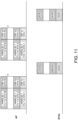
- each block represents a Resource Unit (RU) and the vertical dimension represents elapsed time.
- a RU may be of any type of resource (e.g., time, frequency, space, or any combinations thereof).
- the following MAC procedures may be used.
- the AP may carry a Trigger frame in the same A-MPDU or A-PPDU as the HARQ transmission to trigger responses for HARQ processes.
- the Trigger frame may contain an indication that it is a trigger frame for a HARQ process, as well as the desired HARQ Process ID.
- the response may be scheduled by a response scheduling preamble or header which may contain the desired HARQ Process IDs.
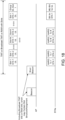
- the AP then conducts additional transmissions and HARQ transmissions based on the feedback received from the STAs. For example, as shown in FIG. 11 , the AP may start a new HARQ process with new transmissions associated with HARQ ID 2 to STA 1 and STA N, since an ACK has been received from STA 1 and STA N indicating that the previous HARQ transmissions have been correctly decoded by STA 1 and STA N. The AP may start to transmit Transmission 2 of HARQ Process ID 1 to STA 2 since a NACK has been received from STA 2 indicating that STA 2 has not successfully decoded the HARQ transmission.
- STA 2 may also include additional feedback in the NACK frame on recommended next step action, including MCS recommendations and whether retransmission or additional RVs are desired.
- Transmission 2 of HARQ Process ID 1 may be a retransmission or may be a different RV of HARQ Process ID 1, which may be based on the recommended actions included in the NACK from STA 2.
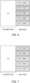
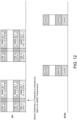
- the A-MPDU or A-PPDU carrying the downlink HARQ transmissions may be composed of two parts, one part of which contains a A-MPDU, while the remaining part may contain a A-PPDU that may contain one or more HARQ transmissions, as shown in FIG. 12 .
- the A-MPDU may be transmitted first and may contain all regular packet transmissions, such as ACK/NACK/BA packets, trigger frames, and other management or control frames, which may be separated by delimiters between the MPDUs.
- the A-MPDU may also contain indications and/or scheduling for the subsequent HARQ transmission(s).
- the A-MPDU may contain information of the upcoming HARQ transmissions, such as for each HARQ transmission, the HARQ Process ID, the targeting receiving STA, the starting time of the HARQ transmission, the Modulation and Coding Scheme (MCS), and the RV numbers of the HARQ transmission. Any or all of these indications may be included in the PLCP or MAC header of the entire A-MPDU as well. Additionally or alternatively, any or all of these indications may be included in the PLCP or MAC header of the entire A-PPDU as well, which may contain the PPDU that carries the A-MPDU.
- MCS Modulation and Coding Scheme
- one or more of the MPDUs that are not a part of the HARQ transmissions may also be grouped into one or more A-MPDUs and may be transmitted in multiple PPDUs of the A-PPDU.
- the transmitting STA may continue to transmit one or more PPDUs, which may contain the HARQ transmissions.
- Each PPDU or HARQ transmission may contain or be preceded by a preamble or separation field which may contain a set of delimiter and/or training fields.
- a preamble or separation field may contain a distinct pattern of bits such as delimiters, training fields such as LTF, STF, or other type of fields to announce the start of a new PPDU or a new HARQ transmission.
- the PPDUs carrying HARQ transmissions may contain or be preceded with a preamble and separation field that may contain delimiters, identifiers for HARQ transmissions, training fields, and/or information related to the upcoming HARQ transmission(s) or PPDUs.
- the (A-)MPDU or PPDU containing one or more MPDUs that are not transmitted as a part of HARQ transmission may be transmitted at the end of the A-PPDU, or anywhere within the A-PPDU.
- the following design is related to example DL HARQ operations and transmission procedures.
- the TF or (A-)PPDU header assigns whether NDP feedback or the BA should be sent in response. In one option, if the assignment is the BA/ack feedback, the AP or non-STA may signal to flush the HARQ buffer such that MPDU-level retransmission may be started with a different MCS.
- the TF may also assign the slave AP HARQ feedback resources for reporting overheard HARQ transmissions. Based on the feedback, the master AP may initiate a joint HARQ re-transmission.
- the NDP feedback resource/tone sets may coincide with the RU assigned to the STA.
- the 'on' tones of the feedback may serve as an auxiliary reciprocity NDP sounding signal to the master and slave APs.
- one or more IDs may be associated with the (A-)PPDU, to be referenced in the retransmission
- the header of the (A-)PPDU or TF may identify a portion of retransmitted OFDM symbols/codewords and/or redundancy version, with reference ID to the original HARQ transmission.
- the receiver simply replies with a BA and optionally includes an indication that the receiver is buffering undecoded HARQ samples.
- the transmitter based on the bitmap on the BA, derives OFDM symbols/codewords to be retransmitted.
- the following exemplary methods may enable and support HARQ downlink multiple stop and wait MAC procedures.
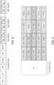
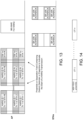
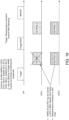
- FIG. 13 An example design of a DL HARQ Multiple Stop and Wait procedure is shown in FIG. 13 .
- the procedures for DL HARQ Multiple Stop and Wait procedure may contain the following steps.
- An AP and a number of STAs may have exchanged capabilities of their support for multiple Stop and Wait HARQ. They may have exchanged the window sizes or the number for concurrently running HARQ processes. Without loss of generality, it is assumed that the number of concurrent HARQ processes per STA or per STA per TID may be N.
- the AP may conduct HARQ transmissions for multiple HARQ processes for each of the STAs on a particular RU. For example, as shown in FIG. 13 , the AP may transmit an A-MPDU or an A-PPDU to STA 1 on RU 0.
- the A-MPDU or A-PPDU may contain a number of PPDUs or MPDUs that may contain multiple transmissions of multiple HARQ processes.
- the PPDU or MPDU may contain the first transmission for STA 1 on RU 0 for HARQ Process 1 - N.
- each of the HARQ transmission may contain or be preceded by a preamble and/or separation field, which may contain a distinct pattern of bits of delimiter, training fields such as LTF, STF, or other type of field to announce the start of a new PPDU, or a new HARQ transmission.
- a preamble and/or separation field which may contain a distinct pattern of bits of delimiter, training fields such as LTF, STF, or other type of field to announce the start of a new PPDU, or a new HARQ transmission.
- the preamble or separation field may also contain information of the upcoming HARQ transmission, such as the HARQ Process ID, the targeting receiving STA, the starting time of the HARQ transmission, the MCS, the RV numbers of the HARQ transmission, retransmission of a previous HARQ transmission, the length of the upcoming HARQ transmission or PPDU, the length or duration of the upcoming HARQ transmission(s) or PPDU(s), as well whether more PPDUs or HARQ transmissions will follow the upcoming HARQ transmission or PPDU.
- information of the upcoming HARQ transmission such as the HARQ Process ID, the targeting receiving STA, the starting time of the HARQ transmission, the MCS, the RV numbers of the HARQ transmission, retransmission of a previous HARQ transmission, the length of the upcoming HARQ transmission or PPDU, the length or duration of the upcoming HARQ transmission(s) or PPDU(s), as well whether more PPDUs or HARQ transmissions will follow the
- the AP may transmit an A-MPDU or A-PPDU for STA 2 on RU 1, which may contain a mix of HARQ transmissions and non-HARQ transmissions.
- One or more PPDUs transmitted on RU 1 may contain the first transmission of HARQ process 1 - N for STA 2.
- the PPDU may contain or be preceded by a preamble and/or separation field, which may contain a distinct pattern of bits such as delimiters, training fields such as LTF, STF, or other types of fields to announce the start of a new PPDU, or a new HARQ transmission, as well as other HARQ related information as described above.
- the PPDUs or MPDUs containing the non-HARQ transmissions may be transmitted first or last in the A-MPDU or A-PPDU, or anywhere there within. Additionally or alternatively, the response to the HARQ transmissions may be triggered or scheduled by response scheduling header of one or more PPDU(s) or MPDUs contained in the same A-MPDU or A-PPDU.
- the AP may then decide to conduct further HARQ transmissions. If one or more HARQ processes has been ACKed by a STA, the AP may continue to transmit HARQ transmissions for new HARQ processes, provided the number of concurrent HARQ processes are still less than or equal to the number of concurrent HARQ processes indicated by the STA. If no response has been received or a NACK has been received for a HARQ process, the AP may decide to conduct retransmission or send additional RVs in the follow up HARQ transmissions.
- a STA may not send BA for reporting the successfully received MPDUs for an established BA agreement with HARQ support, unless it receives a BAR to trigger a BA. In other embodiments, it may.
- a HARQ uplink MAC procedure may include one or more of the following steps.
- An AP and one or more STAs may have exchanged capabilities of UL HARQ transmissions and/or HARQ receptions, as well as HARQ parameters.
- the STA may also include a HARQ BAR frame in order to request responses for the HARQ transmissions.
- the STA may include a NDP packet or a frame with only a MAC header in the A-PPDU or A-MPDU within the MAC header including an indication "immediate ACK" is requested.
- the STA may also include a Multi-HARQ BAR or a Multi-TID Multi-HARQ BAR to request responses for multiple HARQ processes associated with one or more TIDs.
- the packets such as BAR, ACK, or other type of management or control frames that are not a part of the HARQ transmissions may be included in one particular A-MPDU carried in one PPDU.
- the PPDU may also contain or be preceded by a preamble or separation field. This PPDU may also be transmitted as the first PPDU in the A-MPDU or as the last PPDU in the A-MPDU.
- the AP may respond to the HARQ transmission and/or BAR frames by transmitting A-MPDUs in the downlink, which may include BA as well as trigger frames.
- the trigger frames for a particular HARQ process ID for a particular STA may also serve as NACK for that HARQ process.
- the trigger frame may contain a bitmap or a list of HARQ Process IDs for which UL HARQ transmissions may be triggered.
- the AP may also send a Multi-STA Multi-TID Multi-HARQ BA to provide responses to one or more STAs that have transmitted UL transmissions for one or more HARQ processes associated with one or more TIDs.
- the trigger frame may also contain specific HARQ processes or retransmissions or a specific RV number of a HARQ process that it desires to trigger in the uplink.
- the AP may trigger uplink transmissions using response scheduling headers or a trigger frame over the entire channel width that is 20 MHz or wider.
- the trigger frame may include resource allocation for UL transmissions. The transmission of the trigger frames may depend on the indicated buffer status of the STAs, which may have been obtained from previous NDP Feedback reports or buffer status reports which may be contained in MAC headers.
- the DL A-MPDU or A-PPDU may contain an indication of whether additional HARQ processes are pending at the transmitting STAs, for example, by setting the More Data or More Fragment bit in the MAC header in the A-MPDU, or A-PPDU, or in the PPDU which carries the HARQ transmission, or in the PPDU which carries MPDUs that are not part of the HARQ transmission.
- a receiving STA of such DL A-MPDU or A-PPDU may transmit an A-MPDU or A-PPDU in the uplink to the AP on the RU that is allocated to it by a trigger frame or response scheduling header in the DL A-MPDU or A-PPDU.
- the STA may include ACK/NACK/BA/HARQ responses in addition to HARQ transmission 1 associated with HARQ process ID 1 to the AP.
- the UL A-MPDU or A-PPDU may contain an indication of whether additional HARQ processes are pending at the transmitting STAs, for example, by setting the More Data or More Fragment bit in the MAC header in the A-MPDU, or A-PPDU, or in the PPDU which carries the HARQ transmission, or in the PPDU which carries MPDUs that are not part of the HARQ transmission.
- the AP after receiving the UL A-MPDUs or A-PPDUs, may determine the status of the DL HARQ transmissions, and determine whether it can decode one or more transmissions associated with one or more UL HARQ process IDs. It may then transmit the ACK/NACK/BA/response for the UL HARQ transmissions. It may also decide to transmit trigger frames to trigger additional UL HARQ transmissions depending on the status of the UL HARQ transmissions as well as the buffer status or indication of additional pending HARQ transmissions by the STA in the UL.
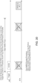
- the AP may also include additional DL HARQ transmissions to the STA based on the feedback received from the STAs. For example, as shown in FIG. 16 , the AP may transmit Transmission 1 associated with HARQ ID 2 to STA 1 and STA 2, on RU 0 and RU 1, respectively, since the HARQ transmission 1 associated with HARQ ID 1 to STA 1 and STA 2 have been ACKed. The AP may transmit Transmission 2 associated with HARQ ID 1 to STA N on RU L since the HARQ processed has been NACKed.
- the AP and the STA may still send an A-MPDU or A-PPDU.
- the MPDUs such as ACK/NACK/BA, BAR, Trigger frame, other type of management or control frames or other type of frames that are not part of a HARQ transmissions may be grouped together in one A-MPDU, which may be carried in one PPDU.
- these MPDUs may be grouped into one or more A-MPDUs, with the A-MPDUs carried in one or more PPDUs.
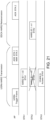
- FIG. 18 is a diagram illustrating an exemplary design for HARQ MAC procedure using TWT or RAW.
- TWT or RAW may have a slotted structure.
- Information regarding TWT or RAW may be included in a beacon, short beacon, FILS discovery frame, or other type of frame.
- a DL slot for a group may be used by the AP to transmit group-based HARQ transmissions in the downlink, and/or Multi-STA Multi-TID Multi-HARQ BA, or Multi-STA Multi HARQ BA to provide responses to one or more STAs for one or more HARQ processes associated with one or more TIDs.
- the AP may acquire the channel and transmit a Trigger frame/MU Request to Send (RTS) to a group of STAs, including STA1 and STA2.
- RTS Trigger frame/MU Request to Send
- a MU RTS frame may be considered as a special form of a Trigger frame. Thus, mention of Trigger frame in this document implies that it may be a MU RTS frame.
- the Trigger frame may be used in UL single user transmission.
- the AP may indicate one or more of the following pieces of information for the upcoming HARQ transmission from the STA(s).
- a HARQ process ID field may be used when more than one HARQ process may be allowed. Specifically, the field may be used to indicate the transmissions related to a set of information bits. The retransmission of the same set of information bits may use the same HARQ process ID. Thus, a STA may use the HARQ process ID to identify the related new transmission and retransmissions.
- a Retransmission Indication field may be used to indicate if the upcoming transmission is a new transmission or a retransmission.
- the Retransmission Indication field may serve as implicit negative acknowledgement transmission, which indicates that the previous transmission may have failed.
- a MCS field may be the same or different from new transmission to retransmission(s).
- HARQ related information may not be carried by the trigger-based PPDU since everything is determined by the AP and the AP knows the HARQ parameters.
- HARQ process ID, RV, retransmission indication and/or MCS may be carried by TB PPDU in the user-specific SIG field. This method may be used in the case that HARQ transmission may be initiated and controlled by the STA. In that case, the Trigger frame that triggers the transmission may not contain HARQ related information.
- the STAs may perform the transmissions as indicated by the AP.
- an AP may include buffer status in the Trigger frame.
- the AP may indicate to a STA that the buffer is reset/flushed and ready for new HARQ transmission.
- the AP may indicate that the buffer may contain transmissions from one or more previous HARQ procedures, which are ready to combine with the retransmission.
- APs and STAs may exchange capabilities to support HARQ transmissions or HARQ transmissions within a TXOP using management/control frames.
- a timer may be provided to indicate the buffer life time.
- a HARQ timer may be introduced at the transmitter and/or receiver side, wherein both the transmitter and the receiver know that a packet transmitted before the timer expires may be decoded using HARQ combining. An exemplary procedure is shown in FIG. 20 .
- the AP may acquire the channel and transmit a Trigger frame/MU RTS to a group of STAs, including STA1 and STA2.
- a MU RTS frame may be considered as a special form of Trigger frame.
- the Trigger frame may be used in UL single user transmission too.
- the AP may indicate one or more of the following pieces of information for the upcoming HARQ transmission from the STA(s).
- a HARQ Trigger field may be used to indicate that the Trigger frame is used to trigger HARQ transmissions.
- the field may be interpreted as a TXOP HARQ Trigger that indicates that HARQ procedures may be valid across multiple TXOPs.
- the AP and STAs should NOT flush HARQ buffer after the end of one TXOP.
- a Max HARQ buffer duration field may be signaled so that the transmitter and receiver know when the timer has expired such that the HARQ buffer may be flushed. Once the HARQ timer is greater than the Max HARQ buffer duration, the receiver may flush the HARQ buffer. Alternatively, the Max HARQ buffer duration may be predefined/predetermined with no need to signal it.
- a HARQ process ID field may be used when more than one HARQ process is allowed. Specifically, this field may be used to indicate the transmissions related to a set of information bits. The retransmission of the same set of information bits may use the same HARQ process ID. Thus, a STA may use the HARQ process ID to determine which original transmission a retransmission is related to.
- a Retransmission Indication field may be used to indicate if the upcoming transmission is a new transmission or a retransmission.
- the Retransmission Indication field may serve as an implicit negative acknowledgement transmission, which indicates that the previous transmission failed.
- a MCS field may indicate the modulation and coding scheme of the transmission.
- the MCS for the retransmission of a piece of information may be the same or different from the MCS of the original transmission.
- Some of the above mentioned fields may be common for all the users and others may be dedicated for a single user.
- a STA may detect that it is the desired STA for the UL HARQ transmission.
- the STA starts a HARQ timer if the STA notices that the Trigger frame is triggering a new transmission (e.g., by checking the Retransmission Indication field or HARQ timer starting indication field). Otherwise, the STA checks whether the HARQ timer is expired. If the timer has not expired or the STA has started a new timer, the STA prepares a HARQ transmission as indicated by the AP. If, on the other hand, the timer has expired and the AP requests a retransmission, the STA may prepare a new transmission of the packet, and indicate in the PLCP header that it may be a new transmission but not a retransmission.
- the STAs may perform retransmissions as indicated by the AP in the same TXOP or later in another TXOP or autonomously by the STA.
- the following information may be carried in the autonomous UL HARQ transmission:
- the data field may be punctured as NDP feedbacks (i.e., inserting LTF portion of a NDP feedback PPDU).
- FIG. 22 An example of punctured LTF for A-PPDU is shown in FIG. 22 .
- a STA (which may or may not be in direct communication with the AP) may use the NDP feedback to estimate the most suitable RUs (e.g., comparing the power on the on-tones, or the noise on the off tones), and the non-AP STA may report this information to the AP.
- 'No response' may not be used for HARQ feedback.
- an electrical system represents data bits that can cause a resulting transformation or reduction of the electrical signals and the maintenance of data bits at memory locations in a memory system to thereby reconfigure or otherwise alter the CPU's operation, as well as other processing of signals.
- the memory locations where data bits are maintained are physical locations that have particular electrical, magnetic, optical, or organic properties corresponding to or representative of the data bits. It should be understood that the representative embodiments are not limited to the above-mentioned platforms or CPUs and that other platforms and CPUs may support the provided methods.
- any of the operations, processes, etc. described herein may be implemented as computer-readable instructions stored on a computer-readable medium.
- the computer-readable instructions may be executed by a processor of a mobile unit, a network element, and/or any other computing device.
- ASICs Application Specific Integrated Circuits
- FPGAs Field Programmable Gate Arrays
- DSPs digital signal processors
- ASICs Application Specific Integrated Circuits
- FPGAs Field Programmable Gate Arrays
- DSPs digital signal processors
- FIG. 1 ASICs
- FIG. 1 ASICs
- FIG. 1 ASICs
- FIG. 1 ASICs
- FIG. 1 ASICs
- FIG. 1 ASICs
- FIG. 1 Application Specific Integrated Circuits
- FPGAs Field Programmable Gate Arrays
- DSPs digital signal processors
- any two components so associated may also be viewed as being “operably connected”, or “operably coupled”, to each other to achieve the desired functionality, and any two components capable of being so associated may also be viewed as being “operably couplable” to each other to achieve the desired functionality.
- operably couplable include but are not limited to physically mateable and/or physically interacting components and/or wirelessly interactable and/or wirelessly interacting components and/or logically interacting and/or logically interactable components.
- the phrase “A or B” will be understood to include the possibilities of “A” or “B” or “A and B.”
- the terms “any of” followed by a listing of a plurality of items and/or a plurality of categories of items, as used herein, are intended to include “any of,” “any combination of,” “any multiple of,” and/or “any combination of multiples of” the items and/or the categories of items, individually or in conjunction with other items and/or other categories of items.
- the term “set” or “group” is intended to include any number of items, including zero.
- the term “number” is intended to include any number, including zero.
- a range includes each individual member.
- a group having 1-3 cells refers to groups having 1, 2, or 3 cells.
- a group having 1-5 cells refers to groups having 1, 2, 3, 4, or 5 cells, and so forth.
Landscapes
- Engineering & Computer Science (AREA)
- Computer Networks & Wireless Communication (AREA)
- Signal Processing (AREA)
- Mobile Radio Communication Systems (AREA)
- Detection And Prevention Of Errors In Transmission (AREA)
Priority Applications (1)
| Application Number | Priority Date | Filing Date | Title |
|---|---|---|---|
| EP25170316.1A EP4601227A3 (en) | 2018-11-08 | 2019-11-01 | Methods and apparatus for harq in wireless networks |
Applications Claiming Priority (2)
| Application Number | Priority Date | Filing Date | Title |
|---|---|---|---|
| US201862757555P | 2018-11-08 | 2018-11-08 | |
| PCT/US2019/059375 WO2020096895A1 (en) | 2018-11-08 | 2019-11-01 | Methods and apparatus for harq in wireless networks |
Related Child Applications (1)
| Application Number | Title | Priority Date | Filing Date |
|---|---|---|---|
| EP25170316.1A Division EP4601227A3 (en) | 2018-11-08 | 2019-11-01 | Methods and apparatus for harq in wireless networks |
Publications (2)
| Publication Number | Publication Date |
|---|---|
| EP3878121A1 EP3878121A1 (en) | 2021-09-15 |
| EP3878121B1 true EP3878121B1 (en) | 2025-04-16 |
Family
ID=68655706
Family Applications (2)
| Application Number | Title | Priority Date | Filing Date |
|---|---|---|---|
| EP19809293.4A Active EP3878121B1 (en) | 2018-11-08 | 2019-11-01 | Methods and apparatus for harq in wireless networks |
| EP25170316.1A Pending EP4601227A3 (en) | 2018-11-08 | 2019-11-01 | Methods and apparatus for harq in wireless networks |
Family Applications After (1)
| Application Number | Title | Priority Date | Filing Date |
|---|---|---|---|
| EP25170316.1A Pending EP4601227A3 (en) | 2018-11-08 | 2019-11-01 | Methods and apparatus for harq in wireless networks |
Country Status (7)
| Country | Link |
|---|---|
| US (2) | US12218763B2 (enExample) |
| EP (2) | EP3878121B1 (enExample) |
| JP (2) | JP7534295B2 (enExample) |
| KR (2) | KR102955603B1 (enExample) |
| CN (3) | CN113039735B (enExample) |
| TW (1) | TWI837209B (enExample) |
| WO (1) | WO2020096895A1 (enExample) |
Families Citing this family (27)
| Publication number | Priority date | Publication date | Assignee | Title |
|---|---|---|---|---|
| CN111200477A (zh) * | 2018-11-19 | 2020-05-26 | 中兴通讯股份有限公司 | 传输数据帧的方法、装置和存储介质 |
| SG10201810792SA (en) * | 2018-11-30 | 2020-06-29 | Panasonic Ip Corp America | Communication devices and communication methods for multi-band traffic streams |
| JP7433321B2 (ja) * | 2019-01-10 | 2024-02-19 | パナソニック インテレクチュアル プロパティ コーポレーション オブ アメリカ | 通信装置、通信方法及び集積回路 |
| WO2020179259A1 (ja) * | 2019-03-07 | 2020-09-10 | パナソニック インテレクチュアル プロパティ コーポレーション オブ アメリカ | 基地局、端末、送信方法及び受信方法 |
| WO2020204298A1 (ko) * | 2019-04-01 | 2020-10-08 | 엘지전자 주식회사 | Harq 재전송을 위한 시간 제한 |
| WO2020204376A1 (ko) * | 2019-04-05 | 2020-10-08 | 엘지전자 주식회사 | Harq 동작을 수행하기 위한 방법 및 장치 |
| GB2585231B (en) * | 2019-07-04 | 2022-09-07 | Canon Kk | Temporary aids for unassociated stations in communication networks |
| GB2585229B (en) * | 2019-07-04 | 2021-10-27 | Canon Kk | Variable configurations of NFRP RU tone sets in wireless networks |
| CN113994614B (zh) * | 2019-07-11 | 2024-06-11 | 松下电器(美国)知识产权公司 | 用于混合自动重复请求传输的通信装置和通信方法 |
| US20210014006A1 (en) * | 2019-07-12 | 2021-01-14 | Samsung Electronics Co., Ltd. | System and method for implementing a hybrid automatic repeat request process |
| SG10201908525WA (en) * | 2019-09-13 | 2021-04-29 | Panasonic Ip Corp America | Communication apparatus and communication method for hybrid automatic repeat request operation |
| KR20260004506A (ko) | 2019-11-22 | 2026-01-08 | 엘지전자 주식회사 | 무선 통신 시스템에서 프리앰블을 구성하기 위한 기법 |
| CN115865571B (zh) * | 2020-06-05 | 2024-01-05 | 华为技术有限公司 | Ppdu的传输方法及相关装置 |
| WO2022015034A1 (ko) * | 2020-07-13 | 2022-01-20 | 주식회사 윌러스표준기술연구소 | 무선 통신 시스템에서 데이터를 송수신하기 위한 방법 및 무선 통신 단말 |
| US12232100B2 (en) * | 2020-09-11 | 2025-02-18 | Qualcomm Incorporated | Limit for retransmission of dropped feedback |
| KR20230073238A (ko) | 2020-09-30 | 2023-05-25 | 광동 오포 모바일 텔레커뮤니케이션즈 코포레이션 리미티드 | 액세스 포인트, 스테이션 및 정보 전송 방법 |
| US11553438B2 (en) * | 2020-10-12 | 2023-01-10 | Mediatek Singapore Pte. Ltd. | Encoding and transmit power control for downsized uplink trigger-based PPDU transmissions in next-generation WLAM systems |
| US20210195478A1 (en) * | 2020-12-15 | 2021-06-24 | Intel Corporation | Configuration of nfrp trigger frame for ndp feedback report procedure |
| WO2022170300A1 (en) * | 2021-02-04 | 2022-08-11 | Qualcomm Incorporated | Dynamic triggering of type 3 codebook feedback |
| US12335993B2 (en) * | 2021-05-05 | 2025-06-17 | Samsung Electronics Co., Ltd. | Inserted PPDU |
| CN115333908B (zh) * | 2021-05-10 | 2024-03-08 | 苏州速通半导体科技有限公司 | 无线局域网中的发射器及由其执行的方法 |
| US12689889B2 (en) | 2021-05-18 | 2026-07-21 | Beijing Xiaomi Mobile Software Co., Ltd. | Information transmission methods and apparatuses |
| JP2024102385A (ja) * | 2021-05-31 | 2024-07-31 | シャープ株式会社 | 通信装置および通信方法 |
| WO2024011108A1 (en) * | 2022-07-08 | 2024-01-11 | Cisco Technology, Inc. | Adding control or management data to block acknowledge or protocol data unit |
| CN115396950B (zh) * | 2022-08-29 | 2025-07-11 | 北京奕斯伟计算技术股份有限公司 | 无线通信设备、系统以及数据聚合方法 |
| US20240292269A1 (en) * | 2023-02-24 | 2024-08-29 | Apple Inc. | Concatenated physical layer convergence protocol (plcp) protocol data units (pdus) |
| US20240380519A1 (en) * | 2023-05-10 | 2024-11-14 | Apple Inc. | Wireless local area network (wlan) link adaptation for multi-user transmission |
Family Cites Families (19)
| Publication number | Priority date | Publication date | Assignee | Title |
|---|---|---|---|---|
| KR100976384B1 (ko) | 2007-02-05 | 2010-08-18 | 삼성전자주식회사 | 광대역 무선통신시스템에서 하이브리드 자동재전송요청시그널링 장치 및 방법 |
| US8611265B2 (en) | 2008-11-26 | 2013-12-17 | Qualcomm Incorporated | Methods and systems for performing HARQ ACK with scanning and sleep in WiMAX systems |
| KR101238889B1 (ko) | 2010-12-28 | 2013-03-04 | 주식회사 포스코 | 고체산화물 연료전지와 이의 제조방법 및 연료극 제조를 위한 테이프 캐스팅 장치 |
| EP2834934B1 (en) | 2012-04-02 | 2022-08-17 | Nokia Solutions and Networks Oy | Hybrid automatic repeat request in communications |
| WO2015006640A1 (en) * | 2013-07-11 | 2015-01-15 | Interdigital Patent Holdings, Inc. | Systems and methods for smart harq for wifi |
| WO2015035558A1 (zh) | 2013-09-10 | 2015-03-19 | 华为技术有限公司 | 一种混合自动重传请求方法、装置及系统 |
| US9876614B1 (en) * | 2014-01-20 | 2018-01-23 | Marvell International Ltd. | Hybrid automatic repeat request for wireless local area network |
| US9967061B2 (en) | 2014-03-10 | 2018-05-08 | Lg Electronics Inc. | Method and apparatus for retransmission in wireless LAN |
| EP4492862A3 (en) * | 2014-03-17 | 2025-03-26 | InterDigital Patent Holdings, Inc. | Methods for reception failure identification and remediation for wifi |
| US10374776B2 (en) * | 2014-11-20 | 2019-08-06 | Industrial Technology Research Institute | Base station, user equipment for integrating multiple rats using carrier aggregation and methods thereof |
| US9948430B2 (en) | 2015-03-17 | 2018-04-17 | Huawei Technologies Co., Ltd. | Method and apparatus for combining data and retransmission data in layer domain |
| US10477528B2 (en) * | 2016-02-02 | 2019-11-12 | Ofinno, Llc | Downlink control information in a wireless device and wireless network |
| US20170230136A1 (en) | 2016-02-04 | 2017-08-10 | Shanghai Research Center For Wireless Communications | Method, base station, and terminal for fusing baseband resources between networks of different standards |
| US10470050B2 (en) * | 2016-11-16 | 2019-11-05 | Apple Inc. | License assisted access uplink communication with Wi-Fi preamble |
| CN111884693B (zh) * | 2017-01-09 | 2024-04-05 | 联发科技股份有限公司 | 用户设备的无线通信方法和用户设备 |
| US11296828B2 (en) * | 2017-11-21 | 2022-04-05 | Lg Electronics Inc. | Method for transmitting or receiving frame in wireless LAN, and device therefor |
| CN110417518B (zh) * | 2018-04-26 | 2022-08-26 | 华为技术有限公司 | 基于harq技术的通信方法、设备及系统 |
| US10999014B2 (en) * | 2018-08-10 | 2021-05-04 | Qualcomm Incorporated | Hybrid automatic repeat request (HARQ) in a wireless local area network (WLAN) |
| US11082156B2 (en) * | 2018-10-30 | 2021-08-03 | Nxp Usa, Inc. | Method and apparatus for generating a physical layer (PHY) data unit for hybrid automatic repeat request (HARQ) |
-
2019
- 2019-11-01 KR KR1020217014475A patent/KR102955603B1/ko active Active
- 2019-11-01 US US17/292,268 patent/US12218763B2/en active Active
- 2019-11-01 WO PCT/US2019/059375 patent/WO2020096895A1/en not_active Ceased
- 2019-11-01 CN CN201980074460.XA patent/CN113039735B/zh active Active
- 2019-11-01 CN CN202410942642.7A patent/CN118713800A/zh active Pending
- 2019-11-01 JP JP2021525213A patent/JP7534295B2/ja active Active
- 2019-11-01 CN CN202410942575.9A patent/CN118677575A/zh active Pending
- 2019-11-01 KR KR1020267011793A patent/KR20260056324A/ko active Pending
- 2019-11-01 EP EP19809293.4A patent/EP3878121B1/en active Active
- 2019-11-01 EP EP25170316.1A patent/EP4601227A3/en active Pending
- 2019-11-04 TW TW108139869A patent/TWI837209B/zh active
-
2024
- 2024-08-01 JP JP2024125959A patent/JP7860179B2/ja active Active
- 2024-12-20 US US18/989,179 patent/US20250233694A1/en active Pending
Also Published As
| Publication number | Publication date |
|---|---|
| US12218763B2 (en) | 2025-02-04 |
| TW202034730A (zh) | 2020-09-16 |
| KR102955603B1 (ko) | 2026-04-21 |
| EP3878121A1 (en) | 2021-09-15 |
| CN113039735B (zh) | 2024-08-02 |
| CN118713800A (zh) | 2024-09-27 |
| EP4601227A3 (en) | 2025-10-22 |
| US20250233694A1 (en) | 2025-07-17 |
| TWI837209B (zh) | 2024-04-01 |
| US20210409165A1 (en) | 2021-12-30 |
| EP4601227A2 (en) | 2025-08-13 |
| KR20260056324A (ko) | 2026-04-24 |
| CN118677575A (zh) | 2024-09-20 |
| WO2020096895A1 (en) | 2020-05-14 |
| JP2022507059A (ja) | 2022-01-18 |
| JP7534295B2 (ja) | 2024-08-14 |
| KR20210096083A (ko) | 2021-08-04 |
| CN113039735A (zh) | 2021-06-25 |
| JP7860179B2 (ja) | 2026-05-15 |
| JP2024153866A (ja) | 2024-10-29 |
Similar Documents
| Publication | Publication Date | Title |
|---|---|---|
| US20250233694A1 (en) | Methods and apparatus for harq in wireless networks | |
| TWI735076B (zh) | 增強具harq設計wlan方法 | |
| US20240322962A1 (en) | Backward compatible physical layer convergence procedure (plcp) protocol data unit (ppdu) design in wireless local area network (wlan) system | |
| EP3592094B1 (en) | Method and apparatus for supporting multi-user transmissions in a wireless local area network (wlan) system | |
| US10218463B2 (en) | Method and system for wireless local area network (WLAN) long symbol duration migration | |
| RU2680193C2 (ru) | Способ передачи данных в системе беспроводной связи и устройство для его осуществления | |
| US20240163019A1 (en) | Methods and wtrus of providing range extension for wlan |
Legal Events
| Date | Code | Title | Description |
|---|---|---|---|
| STAA | Information on the status of an ep patent application or granted ep patent |
Free format text: STATUS: UNKNOWN |
|
| STAA | Information on the status of an ep patent application or granted ep patent |
Free format text: STATUS: THE INTERNATIONAL PUBLICATION HAS BEEN MADE |
|
| PUAI | Public reference made under article 153(3) epc to a published international application that has entered the european phase |
Free format text: ORIGINAL CODE: 0009012 |
|
| STAA | Information on the status of an ep patent application or granted ep patent |
Free format text: STATUS: REQUEST FOR EXAMINATION WAS MADE |
|
| 17P | Request for examination filed |
Effective date: 20210510 |
|
| AK | Designated contracting states |
Kind code of ref document: A1 Designated state(s): AL AT BE BG CH CY CZ DE DK EE ES FI FR GB GR HR HU IE IS IT LI LT LU LV MC MK MT NL NO PL PT RO RS SE SI SK SM TR |
|
| DAV | Request for validation of the european patent (deleted) | ||
| DAX | Request for extension of the european patent (deleted) | ||
| STAA | Information on the status of an ep patent application or granted ep patent |
Free format text: STATUS: EXAMINATION IS IN PROGRESS |
|
| 17Q | First examination report despatched |
Effective date: 20230103 |
|
| RAP3 | Party data changed (applicant data changed or rights of an application transferred) |
Owner name: INTERDIGITAL PATENT HOLDINGS, INC. |
|
| GRAP | Despatch of communication of intention to grant a patent |
Free format text: ORIGINAL CODE: EPIDOSNIGR1 |
|
| STAA | Information on the status of an ep patent application or granted ep patent |
Free format text: STATUS: GRANT OF PATENT IS INTENDED |
|
| INTG | Intention to grant announced |
Effective date: 20241111 |
|
| GRAS | Grant fee paid |
Free format text: ORIGINAL CODE: EPIDOSNIGR3 |
|
| GRAA | (expected) grant |
Free format text: ORIGINAL CODE: 0009210 |
|
| STAA | Information on the status of an ep patent application or granted ep patent |
Free format text: STATUS: THE PATENT HAS BEEN GRANTED |
|
| AK | Designated contracting states |
Kind code of ref document: B1 Designated state(s): AL AT BE BG CH CY CZ DE DK EE ES FI FR GB GR HR HU IE IS IT LI LT LU LV MC MK MT NL NO PL PT RO RS SE SI SK SM TR |
|
| REG | Reference to a national code |
Ref country code: GB Ref legal event code: FG4D |
|
| P01 | Opt-out of the competence of the unified patent court (upc) registered |
Free format text: CASE NUMBER: APP_13087/2025 Effective date: 20250317 |
|
| REG | Reference to a national code |
Ref country code: CH Ref legal event code: EP Ref country code: DE Ref legal event code: R096 Ref document number: 602019068749 Country of ref document: DE |
|
| REG | Reference to a national code |
Ref country code: IE Ref legal event code: FG4D |
|
| REG | Reference to a national code |
Ref country code: NL Ref legal event code: FP |
|
| REG | Reference to a national code |
Ref country code: AT Ref legal event code: MK05 Ref document number: 1786558 Country of ref document: AT Kind code of ref document: T Effective date: 20250416 |
|
| PG25 | Lapsed in a contracting state [announced via postgrant information from national office to epo] |
Ref country code: PT Free format text: LAPSE BECAUSE OF FAILURE TO SUBMIT A TRANSLATION OF THE DESCRIPTION OR TO PAY THE FEE WITHIN THE PRESCRIBED TIME-LIMIT Effective date: 20250818 Ref country code: ES Free format text: LAPSE BECAUSE OF FAILURE TO SUBMIT A TRANSLATION OF THE DESCRIPTION OR TO PAY THE FEE WITHIN THE PRESCRIBED TIME-LIMIT Effective date: 20250416 Ref country code: FI Free format text: LAPSE BECAUSE OF FAILURE TO SUBMIT A TRANSLATION OF THE DESCRIPTION OR TO PAY THE FEE WITHIN THE PRESCRIBED TIME-LIMIT Effective date: 20250416 |
|
| REG | Reference to a national code |
Ref country code: LT Ref legal event code: MG9D |
|
| PG25 | Lapsed in a contracting state [announced via postgrant information from national office to epo] |
Ref country code: NO Free format text: LAPSE BECAUSE OF FAILURE TO SUBMIT A TRANSLATION OF THE DESCRIPTION OR TO PAY THE FEE WITHIN THE PRESCRIBED TIME-LIMIT Effective date: 20250716 Ref country code: GR Free format text: LAPSE BECAUSE OF FAILURE TO SUBMIT A TRANSLATION OF THE DESCRIPTION OR TO PAY THE FEE WITHIN THE PRESCRIBED TIME-LIMIT Effective date: 20250717 |
|
| PG25 | Lapsed in a contracting state [announced via postgrant information from national office to epo] |
Ref country code: PL Free format text: LAPSE BECAUSE OF FAILURE TO SUBMIT A TRANSLATION OF THE DESCRIPTION OR TO PAY THE FEE WITHIN THE PRESCRIBED TIME-LIMIT Effective date: 20250416 |
|
| PG25 | Lapsed in a contracting state [announced via postgrant information from national office to epo] |
Ref country code: BG Free format text: LAPSE BECAUSE OF FAILURE TO SUBMIT A TRANSLATION OF THE DESCRIPTION OR TO PAY THE FEE WITHIN THE PRESCRIBED TIME-LIMIT Effective date: 20250416 |
|
| PG25 | Lapsed in a contracting state [announced via postgrant information from national office to epo] |
Ref country code: HR Free format text: LAPSE BECAUSE OF FAILURE TO SUBMIT A TRANSLATION OF THE DESCRIPTION OR TO PAY THE FEE WITHIN THE PRESCRIBED TIME-LIMIT Effective date: 20250416 |
|
| PG25 | Lapsed in a contracting state [announced via postgrant information from national office to epo] |
Ref country code: AT Free format text: LAPSE BECAUSE OF FAILURE TO SUBMIT A TRANSLATION OF THE DESCRIPTION OR TO PAY THE FEE WITHIN THE PRESCRIBED TIME-LIMIT Effective date: 20250416 |
|
| PG25 | Lapsed in a contracting state [announced via postgrant information from national office to epo] |
Ref country code: RS Free format text: LAPSE BECAUSE OF FAILURE TO SUBMIT A TRANSLATION OF THE DESCRIPTION OR TO PAY THE FEE WITHIN THE PRESCRIBED TIME-LIMIT Effective date: 20250716 |
|
| PG25 | Lapsed in a contracting state [announced via postgrant information from national office to epo] |
Ref country code: IS Free format text: LAPSE BECAUSE OF FAILURE TO SUBMIT A TRANSLATION OF THE DESCRIPTION OR TO PAY THE FEE WITHIN THE PRESCRIBED TIME-LIMIT Effective date: 20250816 |
|
| PG25 | Lapsed in a contracting state [announced via postgrant information from national office to epo] |
Ref country code: LV Free format text: LAPSE BECAUSE OF FAILURE TO SUBMIT A TRANSLATION OF THE DESCRIPTION OR TO PAY THE FEE WITHIN THE PRESCRIBED TIME-LIMIT Effective date: 20250416 |
|
| PGFP | Annual fee paid to national office [announced via postgrant information from national office to epo] |
Ref country code: NL Payment date: 20251124 Year of fee payment: 7 |
|
| PGFP | Annual fee paid to national office [announced via postgrant information from national office to epo] |
Ref country code: DE Payment date: 20251126 Year of fee payment: 7 |
|
| PGFP | Annual fee paid to national office [announced via postgrant information from national office to epo] |
Ref country code: GB Payment date: 20251125 Year of fee payment: 7 |
|
| PG25 | Lapsed in a contracting state [announced via postgrant information from national office to epo] |
Ref country code: SM Free format text: LAPSE BECAUSE OF FAILURE TO SUBMIT A TRANSLATION OF THE DESCRIPTION OR TO PAY THE FEE WITHIN THE PRESCRIBED TIME-LIMIT Effective date: 20250416 Ref country code: DK Free format text: LAPSE BECAUSE OF FAILURE TO SUBMIT A TRANSLATION OF THE DESCRIPTION OR TO PAY THE FEE WITHIN THE PRESCRIBED TIME-LIMIT Effective date: 20250416 |
|
| PGFP | Annual fee paid to national office [announced via postgrant information from national office to epo] |
Ref country code: FR Payment date: 20251125 Year of fee payment: 7 |
|
| REG | Reference to a national code |
Ref country code: DE Ref legal event code: R097 Ref document number: 602019068749 Country of ref document: DE |
|
| PG25 | Lapsed in a contracting state [announced via postgrant information from national office to epo] |
Ref country code: CZ Free format text: LAPSE BECAUSE OF FAILURE TO SUBMIT A TRANSLATION OF THE DESCRIPTION OR TO PAY THE FEE WITHIN THE PRESCRIBED TIME-LIMIT Effective date: 20250416 |
|
| PG25 | Lapsed in a contracting state [announced via postgrant information from national office to epo] |
Ref country code: EE Free format text: LAPSE BECAUSE OF FAILURE TO SUBMIT A TRANSLATION OF THE DESCRIPTION OR TO PAY THE FEE WITHIN THE PRESCRIBED TIME-LIMIT Effective date: 20250416 |
|
| PG25 | Lapsed in a contracting state [announced via postgrant information from national office to epo] |
Ref country code: SK Free format text: LAPSE BECAUSE OF FAILURE TO SUBMIT A TRANSLATION OF THE DESCRIPTION OR TO PAY THE FEE WITHIN THE PRESCRIBED TIME-LIMIT Effective date: 20250416 Ref country code: RO Free format text: LAPSE BECAUSE OF FAILURE TO SUBMIT A TRANSLATION OF THE DESCRIPTION OR TO PAY THE FEE WITHIN THE PRESCRIBED TIME-LIMIT Effective date: 20250416 |
|
| PG25 | Lapsed in a contracting state [announced via postgrant information from national office to epo] |
Ref country code: IT Free format text: LAPSE BECAUSE OF FAILURE TO SUBMIT A TRANSLATION OF THE DESCRIPTION OR TO PAY THE FEE WITHIN THE PRESCRIBED TIME-LIMIT Effective date: 20250416 |
|
| PLBE | No opposition filed within time limit |
Free format text: ORIGINAL CODE: 0009261 |
|
| STAA | Information on the status of an ep patent application or granted ep patent |
Free format text: STATUS: NO OPPOSITION FILED WITHIN TIME LIMIT |
|
| REG | Reference to a national code |
Ref country code: CH Ref legal event code: L10 Free format text: ST27 STATUS EVENT CODE: U-0-0-L10-L00 (AS PROVIDED BY THE NATIONAL OFFICE) Effective date: 20260225 |
|
| 26N | No opposition filed |
Effective date: 20260119 |
|
| REG | Reference to a national code |
Ref country code: CH Ref legal event code: H13 Free format text: ST27 STATUS EVENT CODE: U-0-0-H10-H13 (AS PROVIDED BY THE NATIONAL OFFICE) Effective date: 20260623 |
|
| PG25 | Lapsed in a contracting state [announced via postgrant information from national office to epo] |
Ref country code: LT Free format text: LAPSE BECAUSE OF FAILURE TO SUBMIT A TRANSLATION OF THE DESCRIPTION OR TO PAY THE FEE WITHIN THE PRESCRIBED TIME-LIMIT Effective date: 20250416 |
|
| PG25 | Lapsed in a contracting state [announced via postgrant information from national office to epo] |
Ref country code: MC Free format text: LAPSE BECAUSE OF FAILURE TO SUBMIT A TRANSLATION OF THE DESCRIPTION OR TO PAY THE FEE WITHIN THE PRESCRIBED TIME-LIMIT Effective date: 20250416 |
|
| PG25 | Lapsed in a contracting state [announced via postgrant information from national office to epo] |
Ref country code: LU Free format text: LAPSE BECAUSE OF NON-PAYMENT OF DUE FEES Effective date: 20251101 Ref country code: CH Free format text: LAPSE BECAUSE OF NON-PAYMENT OF DUE FEES Effective date: 20251130 |
|
| PG25 | Lapsed in a contracting state [announced via postgrant information from national office to epo] |
Ref country code: SE Free format text: LAPSE BECAUSE OF FAILURE TO SUBMIT A TRANSLATION OF THE DESCRIPTION OR TO PAY THE FEE WITHIN THE PRESCRIBED TIME-LIMIT Effective date: 20250416 |