EP3877211B1 - Siège escamotable pour véhicule automobile et véhicule comportant un tel siège - Google Patents
Siège escamotable pour véhicule automobile et véhicule comportant un tel siège Download PDFInfo
- Publication number
- EP3877211B1 EP3877211B1 EP19813385.2A EP19813385A EP3877211B1 EP 3877211 B1 EP3877211 B1 EP 3877211B1 EP 19813385 A EP19813385 A EP 19813385A EP 3877211 B1 EP3877211 B1 EP 3877211B1
- Authority
- EP
- European Patent Office
- Prior art keywords
- seat
- frame
- jack
- vehicle
- backrest
- Prior art date
- Legal status (The legal status is an assumption and is not a legal conclusion. Google has not performed a legal analysis and makes no representation as to the accuracy of the status listed.)
- Active
Links
- 238000013016 damping Methods 0.000 claims description 11
- 230000005484 gravity Effects 0.000 description 5
- 230000000694 effects Effects 0.000 description 1
- 230000010354 integration Effects 0.000 description 1
Images


Classifications
-
- B—PERFORMING OPERATIONS; TRANSPORTING
- B60—VEHICLES IN GENERAL
- B60N—SEATS SPECIALLY ADAPTED FOR VEHICLES; VEHICLE PASSENGER ACCOMMODATION NOT OTHERWISE PROVIDED FOR
- B60N2/00—Seats specially adapted for vehicles; Arrangement or mounting of seats in vehicles
- B60N2/24—Seats specially adapted for vehicles; Arrangement or mounting of seats in vehicles for particular purposes or particular vehicles
- B60N2/30—Non-dismountable or dismountable seats storable in a non-use position, e.g. foldable spare seats
- B60N2/3002—Non-dismountable or dismountable seats storable in a non-use position, e.g. foldable spare seats back-rest movements
- B60N2/3004—Non-dismountable or dismountable seats storable in a non-use position, e.g. foldable spare seats back-rest movements by rotation only
- B60N2/3009—Non-dismountable or dismountable seats storable in a non-use position, e.g. foldable spare seats back-rest movements by rotation only about transversal axis
- B60N2/3013—Non-dismountable or dismountable seats storable in a non-use position, e.g. foldable spare seats back-rest movements by rotation only about transversal axis the back-rest being hinged on the vehicle frame
-
- B—PERFORMING OPERATIONS; TRANSPORTING
- B60—VEHICLES IN GENERAL
- B60N—SEATS SPECIALLY ADAPTED FOR VEHICLES; VEHICLE PASSENGER ACCOMMODATION NOT OTHERWISE PROVIDED FOR
- B60N2/00—Seats specially adapted for vehicles; Arrangement or mounting of seats in vehicles
- B60N2/24—Seats specially adapted for vehicles; Arrangement or mounting of seats in vehicles for particular purposes or particular vehicles
- B60N2/30—Non-dismountable or dismountable seats storable in a non-use position, e.g. foldable spare seats
- B60N2/3038—Cushion movements
- B60N2/3063—Cushion movements by composed movement
- B60N2/3065—Cushion movements by composed movement in a longitudinal-vertical plane
-
- B—PERFORMING OPERATIONS; TRANSPORTING
- B60—VEHICLES IN GENERAL
- B60N—SEATS SPECIALLY ADAPTED FOR VEHICLES; VEHICLE PASSENGER ACCOMMODATION NOT OTHERWISE PROVIDED FOR
- B60N2/00—Seats specially adapted for vehicles; Arrangement or mounting of seats in vehicles
- B60N2/24—Seats specially adapted for vehicles; Arrangement or mounting of seats in vehicles for particular purposes or particular vehicles
- B60N2/30—Non-dismountable or dismountable seats storable in a non-use position, e.g. foldable spare seats
- B60N2/3088—Non-dismountable or dismountable seats storable in a non-use position, e.g. foldable spare seats characterised by the mechanical link
- B60N2/309—Non-dismountable or dismountable seats storable in a non-use position, e.g. foldable spare seats characterised by the mechanical link rods
Definitions
- the present invention claims the priority of the application French 1871427 filed on November 09, 2018 .
- the invention relates to the field of interior equipment for motor vehicles.
- the invention relates more particularly to a seat of the retractable type and to a motor vehicle comprising such a seat.
- Motor vehicles in particular of utility type, comprising retractable rear seats are known.
- Such seats are articulated in such a way that it is possible to fold the backrest, and to retract the assembly formed by the folded backrest on the seat in the cavity normally intended for the feet of the passengers.
- the back part of the seatbacks In the retracted position, the back part of the seatbacks is in the extension of the floor of the boot, thus forming a support for long loads.
- the return spring is configured to initiate the retraction movement and drives the seat to a point beyond which the seat is driven by gravity.
- the final part of the retraction movement takes place under the action of gravity.
- Such a configuration can however have a potentially dangerous character. Indeed, the end part of the movement taking place under the action of gravity, the assembly formed by the backrest and the seat can reach a high speed, due to the relatively high weight of this assembly. There is thus a risk that the seat will reach a final speed that is potentially dangerous for the occupant of a neighboring seat, for example if the latter has positioned one of his feet in the path of the seat being retracted. Such a situation should of course be avoided.
- the object of the present invention is to overcome the drawbacks of the state of the art, and more particularly those set out above, by proposing a seat of the retractable type which presents no risk for an occupant of the vehicle during the retraction maneuver.
- the invention relates to a seat of the retractable type for a motor vehicle, the seat comprising a seat comprising a seat frame and a backrest comprising a backrest frame, the seat being configured to assume a normal position, compatible with the reception of a user, and a retracted position, in which the backrest is folded up against the seat, and in which the seat is in a forward and lowered position, at least one terminal part of the movement of passage from the normal position in the retracted position taking place under the action of gravity, the seat comprising a damping device integral with the seat frame on the one hand, and with the backrest frame on the other hand, in order to slow down the final part of this movement.
- the seat is prevented from reaching a high speed which could be dangerous for the users of the vehicle.
- the seat frame is connected to the backrest frame by means of two arms, each arm being articulated on a respective upright of the backrest frame.
- each upright of the backrest frame is intended to be articulated on a rear attachment secured to the body of a vehicle.
- the seat frame comprises two legs that can move in rotation relative to the rest of the seat frame, and each intended to be articulated on a front attachment of the body of a vehicle.
- the damping device is a jack comprising a first part rotatably mounted on one of the arms of the seat frame and a second part rotatably mounted on the corresponding upright of the backrest frame.
- the first part of the jack is a body of the jack, the second part being a rod of the jack, or vice versa.
- the jack is of the hydropneumatic or pneumatic type.
- the seat comprises two actuators arranged on either side of the backrest frame.
- the seat includes at least one return spring configured to urge the seat from its normal position to its retracted position.
- the seat comprises a side casing integral with the backrest covering the damping device.
- the invention also relates to a motor vehicle, comprising at least one seat as defined above.
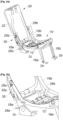
- THE figures 1a and 1b represent a retractable rear seat 1 according to the invention.
- the seat 1 comprises a seat 10 and a backrest 20.
- the seat 10 comprises in particular a seat frame 12 and a seat trim 14, the seat frame 12 being articulated with respect to the body 2 of the motor vehicle in which seat 1 is installed.
- the backrest 20 comprises in particular a backrest frame 22 and a backrest trim 24.
- the seat 1 On the picture 1a , the seat 1 is shown in its normal position I (upright position, allowing a passenger to be seated), and in an intermediate position II, corresponding to the start of the retraction maneuver.
- the backrest 20 In the normal position, the backrest 20 is secured to the body 2 of the vehicle, by means of a locking mechanism (not shown) which can be deactivated by means of a remote control button, arranged for example in the trunk of the vehicle.
- a remote control button arranged for example in the trunk of the vehicle.
- the action of the return spring makes it possible to drive the seat at least up to the intermediate position II visible on the picture 1a , position in which the action of gravity takes over from the action of the return spring, and drives the seat 1 towards its retracted position.
- the angle ⁇ between the normal position I and the intermediate position II which corresponds to the angle between the axes X 1 and X 2 , is between 20 and 45 degrees, and for example greater than or equal to 35 degrees.
- the seat 1 has been shown both in its normal position I and in its retracted position III.
- the retracted position of the seat 1 is such that the seat 10 is housed in the cavity provided for the feet of the occupants of the seat, and the backrest 20 is in a position in which the dorsal part thereof is substantially aligned with the vehicle boot floor.
- the angle ⁇ between the intermediate position II represented on the picture 1a and the retracted position III, which corresponds to the angle between the axes X 1 and X 3 is between 30 and 50 degrees, and for example equal to 40 degrees.
- the angle ⁇ thus represents the range over which the retraction movement of the seat 1 is, in accordance with the invention, braked.
- THE figures 2a and 2b show seat 1 without seat and back upholstery, in its normal position (position I of the picture 1a ).
- THE figures 3a and 3b show seat 1, also without trim, in its retracted position (position III of the figure 1b ).
- the seat frame 12 is connected to the body 2 of the vehicle via two legs 16a, 16b.
- the legs 16a, 16b are articulated, on the one hand, on two front attachments 2a, 2b integral with the body 2 of the vehicle, and, on the other hand, on the seat frame 12.
- the frame 12 is by elsewhere connected to the backrest frame 22 by means of two arms 18a, 18b, each articulated respectively on one of two side uprights 26a, 26b of the backrest frame 22, at the level of a pivot 28a, 28b.
- the uprights 26a, 26b are articulated on two rear attachments 2c, 2d secured to the body of the vehicle.
- this configuration allows the seat 1 to move from the normal position, intended for seating a passenger ( figure 2a ), in the retracted position ( picture 3a ), in which the backrest 20 is tilted forwards and folded against the seat 10, and in which the seat is in a low and advanced position, occupying the cavity intended for the feet of the passengers.
- the seat 1 comprises a damping device 30 connecting the seat frame 12 to the backrest frame 22, in order to slow down the end part of the retraction movement.
- the damping device 30 is a jack, for example of the hydropneumatic or pneumatic type.
- the cylinder 30 comprises a body 32, in the example rotatably mounted on one of the arms 18a of the seat frame 12, and a rod 34, in the example rotatably mounted on the corresponding upright 26a of the backrest frame 22.
- the cylinder 30 is in a retracted configuration when the seat 1 is in the normal position, and in an extended configuration when the seat 1 is in the retracted position.
- the jack 30 is positioned in such a way that the passage of the seat from its normal position to its retracted position has the effect of increasing the distance between the respective attachment points of the body 32 of the jack (on the arm 18a of the seat frame 12) and the rod 34 of the cylinder (on the upright 26a of the backrest frame 22), then biasing the cylinder 30 in extension which, in return, generates a damping force braking the movement of the seat.
- the actuator 30 opposes the passing movement from the normal position to the retracted position of seat 1.
- the jack 30 is of the hydropneumatic type.
- a jack of this type has a reduced size for a given power.
- the anchor point 32a of the actuator 30 on the arm 18a of the seat frame 12 is located close to the pivot 28a.
- the distance between the anchor point 32a and the pivot 28a is in particular between 10 and 40 millimeters, or between 20 and 30 millimeters, and for example equal to 25 millimeters.
- the seat 1 shown in the appended figures comprises a damping device 30 but two damping devices may be provided, one on each side of the seat.
Landscapes
- Engineering & Computer Science (AREA)
- Aviation & Aerospace Engineering (AREA)
- Transportation (AREA)
- Mechanical Engineering (AREA)
- Seats For Vehicles (AREA)
Description
- La présente invention revendique la priorité de la demande
française 1871427 déposée le 09 Novembre 2018 - L'invention se rapporte au domaine des équipements intérieurs des véhicules automobiles. L'invention concerne plus particulièrement un siège de type escamotable et un véhicule automobile comportant un tel siège.
- On connait des véhicules automobiles, notamment de type utilitaire, comportant des sièges arrière escamotables. De tels sièges sont articulés de telle manière qu'il est possible de rabattre le dossier, et d'escamoter l'ensemble formé par le dossier replié sur l'assise dans la cavité normalement destinée aux pieds des passagers. Dans la position escamotée, la partie dorsale des dossiers de sièges se trouve dans le prolongement du plancher du coffre, formant ainsi un support pour des charges longues. Afin de rendre la manoeuvre d'escamotage plus facile, il est connu de prévoir un mécanisme de verrouillage désactivable au moyen d'un bouton de commande déporté du siège correspondant pour être accessible depuis le coffre, couplé à un ressort de rappel qui permet de solliciter le siège vers sa position escamotée. Ainsi, lorsqu'un utilisateur déverrouille un siège au moyen du bouton de commande correspondant, le siège est entrainé de sa position normale vers sa position escamotée par le ressort de rappel. Généralement, le ressort de rappel est configuré de manière à initier le mouvement d'escamotage et entraine le siège jusqu'à un point au-delà duquel le siège est entrainé par la gravité. Ainsi, la partie finale du mouvement d'escamotage se réalise sous l'action de la gravité.
- Une telle configuration peut cependant présenter un caractère potentiellement dangereux. En effet, la partie terminale du mouvement se faisant sous l'action de la gravité, l'ensemble formé par le dossier et l'assise peut atteindre une vitesse importante, en raison du poids relativement élevé de cet ensemble. Il existe ainsi un risque que le siège atteigne une vitesse finale potentiellement dangereuse pour l'occupant d'un siège voisin, par exemple si celui-ci a positionné l'un de ses pieds sur le trajet du siège en cours d'escamotage. Une telle situation doit bien entendu être évitée.
- La demande de brevet
DE4136363 A1 divulgue un exemple de siège escamotable de l'état de la technique. - La présente invention a pour but de pallier les inconvénients de l'état de la technique, et plus particulièrement ceux-ci-dessus exposés, en proposant un siège de type escamotable qui ne présente pas de risque pour un occupant du véhicule lors de la manoeuvre d'escamotage.
- À cet effet, l'invention concerne un siège de type escamotable pour véhicule automobile, le siège comportant une assise comportant une armature d'assise et un dossier comportant une armature de dossier, le siège étant configuré pour prendre une position normale, compatible avec l'accueil d'un utilisateur, et une position escamotée, dans laquelle le dossier est replié contre l'assise, et dans laquelle l'assise est dans une position avancée et abaissée, au moins une partie terminale du mouvement de passage de la position normale à la position escamotée s'effectuant sous l'action de la gravité, le siège comportant un dispositif amortisseur solidaire de l'armature d'assise d'une part, et de l'armature de dossier d'autre part, afin de freiner la partie terminale de ce mouvement.
- Ainsi, en prévoyant un dispositif amortisseur susceptible de freiner le mouvement de passage à la position escamotée du siège, plus particulièrement dans sa partie terminale, on évite que le siège n'atteigne une vitesse importante qui pourrait présenter un caractère dangereux pour les utilisateurs du véhicule.
- Conformément à l'invention, l'armature d'assise est reliée à l'armature de dossier par l'intermédiaire de deux bras, chaque bras étant articulé sur un montant respectif de l'armature de dossier.
- Dans une réalisation, chaque montant de l'armature de dossier est destiné à être articulé sur une attache arrière solidaire de la caisse d'un véhicule.
- Dans une réalisation, l'armature d'assise comporte deux jambes mobiles en rotation par rapport au reste de l'armature d'assise, et destinées à être articulées chacune sur une attache avant de la caisse d'un véhicule.
- Conformément à l'invention, le dispositif amortisseur est un vérin comportant une première partie montée à rotation sur l'un des bras de l'armature d'assise et une deuxième partie montée à rotation sur le montant correspondant de l'armature de dossier.
- Dans une réalisation, la première partie du vérin est un corps du vérin, la deuxième partie étant une tige du vérin, ou inversement.
- Dans une réalisation, le vérin est de type hydropneumatique ou pneumatique.
- Dans une réalisation, le siège comporte deux vérins disposés de part et d'autre de l'armature de dossier.
- Dans une réalisation, le siège comporte au moins un ressort de rappel configuré pour solliciter le siège de sa position normale vers sa position escamotée.
- Dans une réalisation, le siège comporte un carter latéral solidaire du dossier recouvrant le dispositif amortisseur.
- L'invention concerne également un véhicule automobile, comportant au moins un siège tel que défini ci-dessus.
- La présente invention sera mieux comprise à la lecture de la description détaillée qui suit, faite en référence aux dessins annexés, dans lesquels :
- [
Fig. 1a ] représente un siège conforme à l'invention, le siège étant représenté dans sa position normale et dans une position correspondant au début du mouvement d'escamotage ; - [
Fig. 1b ] représente le siège de lafigure 1a , dans sa position et normale et dans une position correspondant à la fin du mouvement d'escamotage ; - [
Fig. 2a ] est une vue en perspective de l'armature d'un siège conforme à l'invention, en position normale ; - [
Fig. 2b ] est une vue de détail de lafigure 2a ; - [
Fig. 3a ] est une vue en perspective de l'armature du siège de lafigure 2a , en position escamotée ; - [
Fig. 3b ] est une vue de détail de lafigure 3a . - Les
figures 1a et 1b représentent un siège 1 arrière escamotable conforme à l'invention. - Le siège 1 comporte une assise 10 et un dossier 20. L'assise 10 comporte notamment une armature d'assise 12 et une garniture d'assise 14, l'armature d'assise 12 étant articulée par rapport à la caisse 2 du véhicule automobile dans lequel le siège 1 est installé. Le dossier 20 comporte notamment une armature de dossier 22 et une garniture de dossier 24.
- Sur la
figure 1a , le siège 1 est représenté dans sa position normale I (position redressée, permettant l'assise d'un passager), et dans une position intermédiaire II, correspondant au début de la manoeuvre d'escamotage. En position normale, le dossier 20 est solidaire de la caisse 2 du véhicule, par l'intermédiaire d'un mécanisme de verrouillage (non représenté) qui peut être désactivé par l'intermédiaire d'un bouton de commande déporté, disposé par exemple dans le coffre du véhicule. Lorsqu'un utilisateur souhaite escamoter le siège 1, il déverrouille celui-ci par l'intermédiaire du bouton de commande correspondant, puis le siège 1 est entrainé dans son mouvement d'escamotage par un ressort de rappel (non représenté). L'action du ressort de rappel permet d'entrainer le siège au moins jusqu'à la position intermédiaire II visible sur lafigure 1a , position dans laquelle l'action de la gravité prend le relais de l'action du ressort de rappel, et entraine le siège 1 vers sa position d'escamotage. L'angle α entre la position normale I et la position intermédiaire II, qui correspond à l'angle entre les axes X1 et X2, est compris entre 20 et 45 degrés, et par exemple supérieur ou égal à 35 degrés. - Sur la
figure 1b , on a représenté le siège 1 à la fois dans sa position normale I et dans sa position escamotée III. Comme visible sur lafigure 1b , la position escamotée du siège 1 est telle que l'assise 10 se trouve logée dans la cavité prévue pour les pieds des occupants du siège, et le dossier 20 se trouve dans une position dans laquelle la partie dorsale de celui-ci est sensiblement alignée avec le plancher du coffre du véhicule. L'angle β entre la position intermédiaire II représentée sur lafigure 1a et la position escamotée III, qui correspond à l'angle entre les axes X1 et X3, est compris entre 30 et 50 degrés, et par exemple égal à 40 degrés. L'angle β représente ainsi la plage sur laquelle le mouvement d'escamotage du siège 1 est, conformément à l'invention, freiné. - Les
figures 2a et 2b montrent le siège 1 dépourvu des garnitures d'assise et de dossier, dans sa position normale (position I de lafigure 1a ). Lesfigures 3a et 3b montrent le siège 1, également dépourvu des garnitures, dans sa position escamotée (position III de lafigure 1b ). - Afin de permettre le mouvement d'escamotage du siège 1, l'armature d'assise 12 est reliée à la caisse 2 du véhicule par l'intermédiaire de deux jambes 16a, 16b. Les jambes 16a, 16b sont articulées, d'une part, sur deux attaches avant 2a, 2b solidaires de la caisse 2 du véhicule, et, d'autre part, sur l'armature d'assise 12. L'armature 12 est par ailleurs reliée à l'armature de dossier 22 par l'intermédiaire de deux bras 18a, 18b, respectivement articulés chacun sur l'un de deux montants 26a, 26b latéraux de l'armature de dossier 22, au niveau d'un pivot 28a, 28b. Les montants 26a, 26b sont articulés sur deux attaches arrière 2c, 2d solidaires de la caisse du véhicule. Comme visible sur les
figures 2a et3a , cette configuration permet au siège 1 de passer de position normale, prévue pour l'assise d'un passager (figure 2a ), à la position escamotée (figure 3a ), dans laquelle le dossier 20 est basculé vers l'avant et replié contre l'assise 10, et dans laquelle l'assise est dans une position basse et avancée, occupant la cavité destinée aux pieds des passagers. - Conformément à l'invention, le siège 1 comporte un dispositif amortisseur 30 reliant l'armature d'assise 12 à l'armature de dossier 22, afin de freiner la partie terminale du mouvement d'escamotage. Conformément à l'invention, le dispositif amortisseur 30 est un vérin, par exemple de type hydropneumatique ou pneumatique. Le vérin 30 comporte un corps 32, dans l'exemple monté à rotation sur l'un des bras 18a de l'armature d'assise 12, et une tige 34, dans l'exemple montée à rotation sur le montant 26a correspondant de l'armature de dossier 22. Bien entendu, on pourra prévoir le montage inversé, le corps 32 du vérin étant monté à rotation sur l'armature de dossier 22, et la tige de vérin 34 étant montée à rotation sur l'armature d'assise 12.
- Comme visible notamment sur les
figures 2b et3b , le vérin 30 est dans une configuration rétractée lorsque le siège 1 est en position normale, et dans une configuration étendue lorsque le siège 1 est en position escamotée. En effet, le vérin 30 est positionné de telle manière que le passage du siège de sa position normale à sa position escamotée a pour effet d'augmenter la distance entre les points de fixation respectifs du corps 32 du vérin (sur le bras 18a de l'armature d'assise 12) et de la tige 34 du vérin (sur le montant 26a de l'armature de dossier 22), sollicitant alors le vérin 30 en extension qui, en retour, génère une force d'amortissement freinant le mouvement du siège. En effet, en s'opposant au mouvement de rotation de l'armature d'assise 12 par rapport à l'armature de dossier 22 lié au repli du dossier 20 sur l'assise 10, le vérin 30 s'oppose au mouvement de passage de la position normale à la position escamotée du siège 1. - Avantageusement, le vérin 30 est de type hydropneumatique. Un vérin de ce type présente une taille réduite pour une puissance donnée.
- Avantageusement, comme visible notamment sur la
figure 2b , le point d'ancrage 32a du vérin 30 sur le bras 18a de l'armature d'assise 12 est situé à proximité du pivot 28a. La distance entre le point d'ancrage 32a et le pivot 28a est notamment comprise entre 10 et 40 millimètres, ou comprise entre 20 et 30 millimètres, et par exemple égale à 25 millimètres. Cette configuration permet d'obtenir un débattement angulaire du vérin réduit lors du passage à la position escamotée (figure 3b ), ce qui réduit son encombrement et facilite son intégration puisque le vérin 30 est positionné sous un carter solidaire du siège. - Le siège 1 représenté sur les figures annexées comporte un dispositif amortisseur 30 mais l'on pourra prévoir deux dispositifs amortisseurs, un de chaque côté du siège.
Claims (8)
- Siège (1) de type escamotable pour véhicule automobile, le siège (1) comportant une assise (10) comportant une armature d'assise (12) et un dossier (20) comportant une armature de dossier (22), le siège étant configuré pour prendre une position normale, compatible avec l'accueil d'un utilisateur, et une position escamotée, dans laquelle le dossier (20) est replié contre l'assise (10), et dans laquelle l'assise (10) est dans une position avancée et abaissée, au moins une partie terminale du mouvement de passage de la position normale à la position escamotée s'effectuant sous l'action de la gravité, le siège comportant un dispositif amortisseur (30) solidaire de l'armature d'assise (12) d'une part, et de l'armature de dossier (22) d'autre part, afin de freiner la partie terminale de ce mouvement, caractérisé en ce que l'armature d'assise (12) est reliée à l'armature de dossier (22) par l'intermédiaire de deux bras (18a, 18b), chaque bras (18a, 18b) étant articulé sur un montant (26a, 26b) respectif de l'armature de dossier (22) et en ce que le dispositif amortisseur est un vérin (30) comportant une première partie (32) montée à rotation sur l'un des bras (18a, 18b) de l'armature d'assise (12) et une deuxième partie (34) montée à rotation sur le montant (26a, 26b) correspondant de l'armature de dossier (22).
- Siège (1) selon la revendication précédente, dans lequel chaque montant (26a, 26b) de l'armature de dossier (22) est destiné à être articulé sur une attache arrière (2c, 2d) solidaire de la caisse d'un véhicule.
- Siège (1) selon l'une des revendications précédentes, dans lequel l'armature d'assise (12) comporte deux jambes (16a, 16b), mobiles en rotation par rapport au reste de l'armature d'assise (12), et destinées à être articulées chacune sur une attache avant (2a, 2b) de la caisse d'un véhicule.
- Siège (1) selon la revendication 1, dans laquelle la première partie du vérin est un corps (32) du vérin (30), la deuxième partie étant une tige du vérin (34), ou inversement.
- Siège (1) selon l'une des revendications 1 et 4, dans lequel le vérin (30) est de type hydropneumatique ou pneumatique.
- Siège (1) selon l'une des revendications 1 à 5, comportant deux vérins (30), disposés de part et d'autre de l'armature de dossier (22).
- Siège (1) selon l'une des revendications précédentes, comportant au moins un ressort de rappel configuré pour solliciter le siège de sa position normale vers sa position escamotée.
- Véhicule automobile, comportant au moins un siège (1) conforme à l'une des revendications précédentes.
Applications Claiming Priority (2)
| Application Number | Priority Date | Filing Date | Title |
|---|---|---|---|
| FR1871427A FR3088262B1 (fr) | 2018-11-09 | 2018-11-09 | Siege escamotable pour vehicule automobile et vehicule comportant un tel siege |
| PCT/FR2019/052556 WO2020094946A1 (fr) | 2018-11-09 | 2019-10-25 | Siège escamotable pour véhicule automobile et véhicule comportant un tel siège |
Publications (2)
| Publication Number | Publication Date |
|---|---|
| EP3877211A1 EP3877211A1 (fr) | 2021-09-15 |
| EP3877211B1 true EP3877211B1 (fr) | 2023-09-06 |
Family
ID=66041567
Family Applications (1)
| Application Number | Title | Priority Date | Filing Date |
|---|---|---|---|
| EP19813385.2A Active EP3877211B1 (fr) | 2018-11-09 | 2019-10-25 | Siège escamotable pour véhicule automobile et véhicule comportant un tel siège |
Country Status (4)
| Country | Link |
|---|---|
| EP (1) | EP3877211B1 (fr) |
| ES (1) | ES2959549T3 (fr) |
| FR (1) | FR3088262B1 (fr) |
| WO (1) | WO2020094946A1 (fr) |
Family Cites Families (2)
| Publication number | Priority date | Publication date | Assignee | Title |
|---|---|---|---|---|
| DE4136363C2 (de) * | 1991-11-05 | 1995-08-31 | Audi Ag | Rücksitz für Kraftfahrzeuge |
| DE502006009121D1 (de) * | 2005-09-09 | 2011-04-28 | Johnson Controls Gmbh | Fahrzeugsitz |
-
2018
- 2018-11-09 FR FR1871427A patent/FR3088262B1/fr active Active
-
2019
- 2019-10-25 WO PCT/FR2019/052556 patent/WO2020094946A1/fr unknown
- 2019-10-25 ES ES19813385T patent/ES2959549T3/es active Active
- 2019-10-25 EP EP19813385.2A patent/EP3877211B1/fr active Active
Also Published As
| Publication number | Publication date |
|---|---|
| FR3088262A1 (fr) | 2020-05-15 |
| EP3877211A1 (fr) | 2021-09-15 |
| WO2020094946A1 (fr) | 2020-05-14 |
| FR3088262B1 (fr) | 2021-03-05 |
| ES2959549T3 (es) | 2024-02-26 |
Similar Documents
| Publication | Publication Date | Title |
|---|---|---|
| FR2895336A1 (fr) | Appui-tete escamotable pour vehicule automobile | |
| FR2899160A1 (fr) | Siege arriere reglable de vehicule automobile | |
| FR3042450A1 (fr) | Accoudoir escamotable pour siege avant de vehicule automobile | |
| WO2005051704A1 (fr) | Siege reglable pour vehicule automobile, et vehicule automobile equipe d'un tel siege. | |
| EP3877211B1 (fr) | Siège escamotable pour véhicule automobile et véhicule comportant un tel siège | |
| EP0770517A1 (fr) | Siège auxiliaire | |
| EP1839965B1 (fr) | Dispositif d'escamotage et/ou de relevage d'un brin boucle pour ceinture de sécurité de véhicule automobile | |
| EP1707431A2 (fr) | Dispositif de manoeuvre d'un siège de véhicule | |
| EP1808330B1 (fr) | Siège pour véhicule automobile mobile selon un premier axe x et un second axe y et véhicule automobile comprenant un tel siège | |
| FR2846921A1 (fr) | Siege de vehicule dote d'un dispositif de protection du cou en cas de choc arriere | |
| FR2686297A1 (fr) | Siege transformable pour vehicule permettant de transporter un enfant assis dans le sens oppose a la route. | |
| FR2894194A1 (fr) | Siege de vehicule comportant une partie reglable en position | |
| FR3071201B1 (fr) | Accoudoir de pilier central | |
| EP1767395B1 (fr) | Siège pliable pour coffre de véhicule automobile | |
| EP3023295B1 (fr) | Siege de vehicule automobile muni d'une assise rabattable vers le dossier | |
| EP2152540A2 (fr) | Siege escamotable notamment pour vehicule automobile | |
| WO2013050719A1 (fr) | Siege escamotable et cinematique de celui-ci | |
| FR2863560A1 (fr) | Siege de vehicule automobile avec rabattement separe du bloc d'assise et de l'element de dossier | |
| WO2012080663A1 (fr) | Siege de vehicule automobile | |
| EP3524476B1 (fr) | Dispositif de cloisonnement pour vehicule | |
| EP3808593B1 (fr) | Siège à dossier réversible doté d'accoudoirs fixes | |
| EP2095992B1 (fr) | Siège de véhicule automobile, à appuie tête escamotable | |
| FR2902377A1 (fr) | Siegee vehicule automobile a bourrelet escamotable | |
| FR3134077A1 (fr) | Dispositif de retenue en rotation d'une partie mobile d'un élément de mobilier en cas de forte accélération | |
| WO2024115597A1 (fr) | Siège muni d'un dispositif de rétraction d'un repose-tête |
Legal Events
| Date | Code | Title | Description |
|---|---|---|---|
| STAA | Information on the status of an ep patent application or granted ep patent |
Free format text: STATUS: UNKNOWN |
|
| STAA | Information on the status of an ep patent application or granted ep patent |
Free format text: STATUS: THE INTERNATIONAL PUBLICATION HAS BEEN MADE |
|
| PUAI | Public reference made under article 153(3) epc to a published international application that has entered the european phase |
Free format text: ORIGINAL CODE: 0009012 |
|
| STAA | Information on the status of an ep patent application or granted ep patent |
Free format text: STATUS: REQUEST FOR EXAMINATION WAS MADE |
|
| 17P | Request for examination filed |
Effective date: 20210506 |
|
| AK | Designated contracting states |
Kind code of ref document: A1 Designated state(s): AL AT BE BG CH CY CZ DE DK EE ES FI FR GB GR HR HU IE IS IT LI LT LU LV MC MK MT NL NO PL PT RO RS SE SI SK SM TR |
|
| DAV | Request for validation of the european patent (deleted) | ||
| DAX | Request for extension of the european patent (deleted) | ||
| GRAP | Despatch of communication of intention to grant a patent |
Free format text: ORIGINAL CODE: EPIDOSNIGR1 |
|
| STAA | Information on the status of an ep patent application or granted ep patent |
Free format text: STATUS: GRANT OF PATENT IS INTENDED |
|
| INTG | Intention to grant announced |
Effective date: 20230502 |
|
| GRAS | Grant fee paid |
Free format text: ORIGINAL CODE: EPIDOSNIGR3 |
|
| GRAA | (expected) grant |
Free format text: ORIGINAL CODE: 0009210 |
|
| STAA | Information on the status of an ep patent application or granted ep patent |
Free format text: STATUS: THE PATENT HAS BEEN GRANTED |
|
| AK | Designated contracting states |
Kind code of ref document: B1 Designated state(s): AL AT BE BG CH CY CZ DE DK EE ES FI FR GB GR HR HU IE IS IT LI LT LU LV MC MK MT NL NO PL PT RO RS SE SI SK SM TR |
|
| REG | Reference to a national code |
Ref country code: GB Ref legal event code: FG4D Free format text: NOT ENGLISH |
|
| REG | Reference to a national code |
Ref country code: DE Ref legal event code: R084 Ref document number: 602019036978 Country of ref document: DE |
|
| REG | Reference to a national code |
Ref country code: CH Ref legal event code: EP |
|
| REG | Reference to a national code |
Ref country code: DE Ref legal event code: R096 Ref document number: 602019036978 Country of ref document: DE |
|
| REG | Reference to a national code |
Ref country code: IE Ref legal event code: FG4D Free format text: LANGUAGE OF EP DOCUMENT: FRENCH |
|
| REG | Reference to a national code |
Ref country code: GB Ref legal event code: 746 Effective date: 20231005 |
|
| RAP4 | Party data changed (patent owner data changed or rights of a patent transferred) |
Owner name: STELLANTIS AUTO SAS |
|
| REG | Reference to a national code |
Ref country code: LT Ref legal event code: MG9D |
|
| REG | Reference to a national code |
Ref country code: NL Ref legal event code: MP Effective date: 20230906 |
|
| PG25 | Lapsed in a contracting state [announced via postgrant information from national office to epo] |
Ref country code: GR Free format text: LAPSE BECAUSE OF FAILURE TO SUBMIT A TRANSLATION OF THE DESCRIPTION OR TO PAY THE FEE WITHIN THE PRESCRIBED TIME-LIMIT Effective date: 20231207 |
|
| PGFP | Annual fee paid to national office [announced via postgrant information from national office to epo] |
Ref country code: GB Payment date: 20231019 Year of fee payment: 5 |
|
| PGFP | Annual fee paid to national office [announced via postgrant information from national office to epo] |
Ref country code: ES Payment date: 20231103 Year of fee payment: 5 |
|
| PG25 | Lapsed in a contracting state [announced via postgrant information from national office to epo] |
Ref country code: SE Free format text: LAPSE BECAUSE OF FAILURE TO SUBMIT A TRANSLATION OF THE DESCRIPTION OR TO PAY THE FEE WITHIN THE PRESCRIBED TIME-LIMIT Effective date: 20230906 Ref country code: RS Free format text: LAPSE BECAUSE OF FAILURE TO SUBMIT A TRANSLATION OF THE DESCRIPTION OR TO PAY THE FEE WITHIN THE PRESCRIBED TIME-LIMIT Effective date: 20230906 Ref country code: NO Free format text: LAPSE BECAUSE OF FAILURE TO SUBMIT A TRANSLATION OF THE DESCRIPTION OR TO PAY THE FEE WITHIN THE PRESCRIBED TIME-LIMIT Effective date: 20231206 Ref country code: LV Free format text: LAPSE BECAUSE OF FAILURE TO SUBMIT A TRANSLATION OF THE DESCRIPTION OR TO PAY THE FEE WITHIN THE PRESCRIBED TIME-LIMIT Effective date: 20230906 Ref country code: LT Free format text: LAPSE BECAUSE OF FAILURE TO SUBMIT A TRANSLATION OF THE DESCRIPTION OR TO PAY THE FEE WITHIN THE PRESCRIBED TIME-LIMIT Effective date: 20230906 Ref country code: HR Free format text: LAPSE BECAUSE OF FAILURE TO SUBMIT A TRANSLATION OF THE DESCRIPTION OR TO PAY THE FEE WITHIN THE PRESCRIBED TIME-LIMIT Effective date: 20230906 Ref country code: GR Free format text: LAPSE BECAUSE OF FAILURE TO SUBMIT A TRANSLATION OF THE DESCRIPTION OR TO PAY THE FEE WITHIN THE PRESCRIBED TIME-LIMIT Effective date: 20231207 Ref country code: FI Free format text: LAPSE BECAUSE OF FAILURE TO SUBMIT A TRANSLATION OF THE DESCRIPTION OR TO PAY THE FEE WITHIN THE PRESCRIBED TIME-LIMIT Effective date: 20230906 |
|
| PGFP | Annual fee paid to national office [announced via postgrant information from national office to epo] |
Ref country code: FR Payment date: 20231019 Year of fee payment: 5 Ref country code: DE Payment date: 20230920 Year of fee payment: 5 |
|
| REG | Reference to a national code |
Ref country code: AT Ref legal event code: MK05 Ref document number: 1608133 Country of ref document: AT Kind code of ref document: T Effective date: 20230906 |
|
| REG | Reference to a national code |
Ref country code: ES Ref legal event code: FG2A Ref document number: 2959549 Country of ref document: ES Kind code of ref document: T3 Effective date: 20240226 |
|
| PG25 | Lapsed in a contracting state [announced via postgrant information from national office to epo] |
Ref country code: NL Free format text: LAPSE BECAUSE OF FAILURE TO SUBMIT A TRANSLATION OF THE DESCRIPTION OR TO PAY THE FEE WITHIN THE PRESCRIBED TIME-LIMIT Effective date: 20230906 |
|
| PG25 | Lapsed in a contracting state [announced via postgrant information from national office to epo] |
Ref country code: IS Free format text: LAPSE BECAUSE OF FAILURE TO SUBMIT A TRANSLATION OF THE DESCRIPTION OR TO PAY THE FEE WITHIN THE PRESCRIBED TIME-LIMIT Effective date: 20240106 |
|
| REG | Reference to a national code |
Ref country code: DE Ref legal event code: R081 Ref document number: 602019036978 Country of ref document: DE Owner name: STELLANTIS AUTO SAS, FR Free format text: FORMER OWNER: PSA AUTOMOBILES SA, POISSY, FR |
|
| REG | Reference to a national code |
Ref country code: ES Ref legal event code: GC2A Effective date: 20240415 |
|
| PG25 | Lapsed in a contracting state [announced via postgrant information from national office to epo] |
Ref country code: AT Free format text: LAPSE BECAUSE OF FAILURE TO SUBMIT A TRANSLATION OF THE DESCRIPTION OR TO PAY THE FEE WITHIN THE PRESCRIBED TIME-LIMIT Effective date: 20230906 |
|
| PG25 | Lapsed in a contracting state [announced via postgrant information from national office to epo] |
Ref country code: SM Free format text: LAPSE BECAUSE OF FAILURE TO SUBMIT A TRANSLATION OF THE DESCRIPTION OR TO PAY THE FEE WITHIN THE PRESCRIBED TIME-LIMIT Effective date: 20230906 Ref country code: RO Free format text: LAPSE BECAUSE OF FAILURE TO SUBMIT A TRANSLATION OF THE DESCRIPTION OR TO PAY THE FEE WITHIN THE PRESCRIBED TIME-LIMIT Effective date: 20230906 Ref country code: IS Free format text: LAPSE BECAUSE OF FAILURE TO SUBMIT A TRANSLATION OF THE DESCRIPTION OR TO PAY THE FEE WITHIN THE PRESCRIBED TIME-LIMIT Effective date: 20240106 Ref country code: EE Free format text: LAPSE BECAUSE OF FAILURE TO SUBMIT A TRANSLATION OF THE DESCRIPTION OR TO PAY THE FEE WITHIN THE PRESCRIBED TIME-LIMIT Effective date: 20230906 Ref country code: CZ Free format text: LAPSE BECAUSE OF FAILURE TO SUBMIT A TRANSLATION OF THE DESCRIPTION OR TO PAY THE FEE WITHIN THE PRESCRIBED TIME-LIMIT Effective date: 20230906 Ref country code: AT Free format text: LAPSE BECAUSE OF FAILURE TO SUBMIT A TRANSLATION OF THE DESCRIPTION OR TO PAY THE FEE WITHIN THE PRESCRIBED TIME-LIMIT Effective date: 20230906 Ref country code: SK Free format text: LAPSE BECAUSE OF FAILURE TO SUBMIT A TRANSLATION OF THE DESCRIPTION OR TO PAY THE FEE WITHIN THE PRESCRIBED TIME-LIMIT Effective date: 20230906 Ref country code: PT Free format text: LAPSE BECAUSE OF FAILURE TO SUBMIT A TRANSLATION OF THE DESCRIPTION OR TO PAY THE FEE WITHIN THE PRESCRIBED TIME-LIMIT Effective date: 20240108 |