EP3876509A1 - Reading device, image processing apparatus, and method of detecting feature amount - Google Patents
Reading device, image processing apparatus, and method of detecting feature amount Download PDFInfo
- Publication number
- EP3876509A1 EP3876509A1 EP21159319.9A EP21159319A EP3876509A1 EP 3876509 A1 EP3876509 A1 EP 3876509A1 EP 21159319 A EP21159319 A EP 21159319A EP 3876509 A1 EP3876509 A1 EP 3876509A1
- Authority
- EP
- European Patent Office
- Prior art keywords
- image
- edge
- invisible
- visible
- subject
- Prior art date
- Legal status (The legal status is an assumption and is not a legal conclusion. Google has not performed a legal analysis and makes no representation as to the accuracy of the status listed.)
- Granted
Links
- 238000012545 processing Methods 0.000 title claims description 53
- 238000000034 method Methods 0.000 title claims description 27
- 238000003384 imaging method Methods 0.000 claims abstract description 34
- 238000005286 illumination Methods 0.000 claims abstract description 8
- 230000003595 spectral effect Effects 0.000 claims description 17
- 238000010586 diagram Methods 0.000 description 49
- 238000001514 detection method Methods 0.000 description 38
- 238000012546 transfer Methods 0.000 description 21
- 238000003708 edge detection Methods 0.000 description 19
- 238000003702 image correction Methods 0.000 description 14
- 230000003287 optical effect Effects 0.000 description 12
- 230000006870 function Effects 0.000 description 11
- 238000012937 correction Methods 0.000 description 9
- 238000000605 extraction Methods 0.000 description 7
- 230000000694 effects Effects 0.000 description 6
- 230000008569 process Effects 0.000 description 5
- 238000012015 optical character recognition Methods 0.000 description 4
- 230000008901 benefit Effects 0.000 description 3
- 239000011521 glass Substances 0.000 description 3
- 230000002093 peripheral effect Effects 0.000 description 3
- 238000004364 calculation method Methods 0.000 description 2
- 239000003086 colorant Substances 0.000 description 2
- 239000000284 extract Substances 0.000 description 2
- 230000001678 irradiating effect Effects 0.000 description 2
- 239000011159 matrix material Substances 0.000 description 2
- 230000009467 reduction Effects 0.000 description 2
- 230000001052 transient effect Effects 0.000 description 2
- -1 and as a result Substances 0.000 description 1
- 238000004040 coloring Methods 0.000 description 1
- 230000000295 complement effect Effects 0.000 description 1
- 239000012050 conventional carrier Substances 0.000 description 1
- 230000006872 improvement Effects 0.000 description 1
- 230000001788 irregular Effects 0.000 description 1
- 239000000463 material Substances 0.000 description 1
- 238000005259 measurement Methods 0.000 description 1
- 230000007246 mechanism Effects 0.000 description 1
- 229910044991 metal oxide Inorganic materials 0.000 description 1
- 150000004706 metal oxides Chemical class 0.000 description 1
- 239000000203 mixture Substances 0.000 description 1
- 238000012986 modification Methods 0.000 description 1
- 230000004048 modification Effects 0.000 description 1
- 230000002441 reversible effect Effects 0.000 description 1
- 239000004065 semiconductor Substances 0.000 description 1
- 239000007787 solid Substances 0.000 description 1
- 230000003068 static effect Effects 0.000 description 1
- 239000000758 substrate Substances 0.000 description 1
Images


Classifications
-
- H—ELECTRICITY
- H04—ELECTRIC COMMUNICATION TECHNIQUE
- H04N—PICTORIAL COMMUNICATION, e.g. TELEVISION
- H04N1/00—Scanning, transmission or reproduction of documents or the like, e.g. facsimile transmission; Details thereof
- H04N1/00681—Detecting the presence, position or size of a sheet or correcting its position before scanning
- H04N1/00684—Object of the detection
- H04N1/00718—Skew
-
- H—ELECTRICITY
- H04—ELECTRIC COMMUNICATION TECHNIQUE
- H04N—PICTORIAL COMMUNICATION, e.g. TELEVISION
- H04N1/00—Scanning, transmission or reproduction of documents or the like, e.g. facsimile transmission; Details thereof
- H04N1/387—Composing, repositioning or otherwise geometrically modifying originals
- H04N1/3877—Image rotation
- H04N1/3878—Skew detection or correction
-
- H—ELECTRICITY
- H04—ELECTRIC COMMUNICATION TECHNIQUE
- H04N—PICTORIAL COMMUNICATION, e.g. TELEVISION
- H04N1/00—Scanning, transmission or reproduction of documents or the like, e.g. facsimile transmission; Details thereof
- H04N1/00681—Detecting the presence, position or size of a sheet or correcting its position before scanning
- H04N1/00729—Detection means
- H04N1/00734—Optical detectors
- H04N1/00737—Optical detectors using the scanning elements as detectors
-
- H—ELECTRICITY
- H04—ELECTRIC COMMUNICATION TECHNIQUE
- H04N—PICTORIAL COMMUNICATION, e.g. TELEVISION
- H04N1/00—Scanning, transmission or reproduction of documents or the like, e.g. facsimile transmission; Details thereof
- H04N1/00681—Detecting the presence, position or size of a sheet or correcting its position before scanning
- H04N1/00742—Detection methods
- H04N1/00748—Detecting edges, e.g. of a stationary sheet
-
- H—ELECTRICITY
- H04—ELECTRIC COMMUNICATION TECHNIQUE
- H04N—PICTORIAL COMMUNICATION, e.g. TELEVISION
- H04N1/00—Scanning, transmission or reproduction of documents or the like, e.g. facsimile transmission; Details thereof
- H04N1/00681—Detecting the presence, position or size of a sheet or correcting its position before scanning
- H04N1/00742—Detection methods
- H04N1/0075—Detecting a change in reflectivity
-
- H—ELECTRICITY
- H04—ELECTRIC COMMUNICATION TECHNIQUE
- H04N—PICTORIAL COMMUNICATION, e.g. TELEVISION
- H04N1/00—Scanning, transmission or reproduction of documents or the like, e.g. facsimile transmission; Details thereof
- H04N1/00681—Detecting the presence, position or size of a sheet or correcting its position before scanning
- H04N1/00742—Detection methods
- H04N1/00755—Detecting an interruption of light
Definitions
- Embodiments of the present disclosure relate to a reading device, an image processing apparatus, and a method of detecting a feature amount.
- an image processing technique for detecting an edge between a document and a background from an image and correcting an inclination and a position of the document based on the detected edge between the document and the background is known.
- JP-2014-053739-A discloses a technique in which an infrared light low reflection portion is provided as a background, and an edge between a document and the background is detected based on an acquired infrared image so that the edge between the document and the background is extracted.
- the infrared light low reflection portion is provided as the background, and edge detection of detecting the edge between the document and the background is performed based on the acquired infrared image, there is an issue that the edge detection is not successfully performed depending on a color of the document.
- an object of one or more embodiments of the present disclosure is to achieve stable edge detection of detecting an edge between a document and a background regardless of a type of the document.
- An exemplary embodiment of the present disclosure includes a reading device (101) including an illumination unit (2), an imaging unit (22), a background portion (13), and an image processor (20, 201).
- the illumination unit (2) irradiates visible light and invisible light to a subject.
- the imaging unit (22) receives the visible light and the invisible light, each of which is reflected from the subject, to capture a visible image and an invisible image.
- the background portion (13) is provided in an image capturing range of the imaging unit (22).
- the image processor (20, 201) detects a feature amount of the subject and the background portion (13) from at least one of the visible image and the invisible image.
- FIG. 1 is a view illustrating an exemplary configuration of an image forming apparatus 100 according to a first embodiment of the disclosure.
- the image forming apparatus 100 which serves as an image processing apparatus, is an apparatus generally referred to as a multifunction peripheral (MFP) that has at least two functions among a copy function, a printer function, a scanner function, and a facsimile function.
- MFP multifunction peripheral
- the image forming apparatus 100 includes an image reading device 101 serving as a reading device, an automatic document feeder (ADF) 102, and an image forming device 103 provided below the image reading device 101.
- the image forming device 103 is configured to form an image.
- FIG. 1 illustrates the internal configuration of the image forming device 103 from which an external cover is removed.
- the ADF 102 is a document supporter that positions, at a reading position, a document including an image to be read.
- the ADF 102 automatically feeds the document placed on a placement table to the reading position.
- the image reading device 101 reads the document fed by the ADF 102 at a predetermined reading position.
- the image reading device 101 has, on a top surface, a contact glass that is the document supporter, on which a document is placed, and reads the document on the contact glass that is at the reading position.
- the image reading device 101 is a scanner including a light source, an optical system, and a solid-state imaging element such as a complementary metal oxide semiconductor (CMOS) image sensor inside, and reads, by the solid-state imaging element through the optical system, reflected light of the document, which is illuminated, or irradiated, by the light source.
- CMOS complementary metal oxide semiconductor
- the image forming device 103 includes a manual feed roller pair 104 for manually feeding a recording sheet, and a recording sheet supply unit 107 for supplying the recording sheet.
- the recording sheet supply unit 107 includes a mechanism for feeding out the recording sheet from multi-stage recording paper feed cassettes 107a. The recording sheet thus supplied is sent to a secondary transfer belt 112 via a registration roller pair 108.
- a secondary transfer device 114 transfers a toner image from an intermediate transfer belt 113 onto the recording sheet conveyed on the secondary transfer belt 112.
- the image forming device 103 also includes an optical writing device 109, an image forming unit (for yellow (Y), magenta (M), cyan (C), and black (K)) 105 employing a tandem system, the intermediate transfer belt 113, and the secondary transfer belt 112. Specifically, in an image forming process, the image forming unit 105 renders an image written by the optical writing device 109 as a toner image and forms the toner image on the intermediate transfer belt 113.
- the image forming unit (for Y, M, C, and K) 105 includes four photoconductor drums (Y, M, C, and K) in a rotatable manner, and image forming elements 106 each including a charging roller, a developing device, a primary transfer roller, a cleaner unit, and a static eliminator around the respective photoconductor drums.
- the image forming element 106 functions on each photoconductor drum, and the image on the photoconductor drum is transferred onto the intermediate transfer belt 113 by each primary transfer roller.
- the intermediate transfer belt 113 is arranged to be stretched by a drive roller and a driven roller at a nip between each photoconductor drum and each primary transfer roller.
- the toner image primarily transferred onto the intermediate transfer belt 113 is secondarily transferred onto the recording sheet on the secondary transfer belt 112 by a secondary transfer device as the intermediate transfer belt 113 runs.
- the recording sheet is conveyed to a fixing device 110 as the secondary transfer belt 112 runs, and the toner image is fixed as a color image on the recording sheet.
- the recording sheet is discharged onto an output tray disposed outside a housing of the image forming apparatus 100.
- a reverse assembly 111 reverses the front and back sides of the recording sheet and sends out the reversed recording sheet onto the secondary transfer belt 112.
- the image forming device 103 is not limited to the one that forms an image by an electrophotographic method as described above.
- the image forming device 103 may be one that forms an image by an inkjet method.
- FIG. 2 is a cross-sectional view exemplarily illustrating a structure of the image reading device 101 according to the present embodiment.
- the image reading device 101 includes, in a housing 11, a sensor substrate 10 provided with an imaging unit (image sensor) 22, which is a solid-state imaging element, a lens unit 8, a first carriage 6, and a second carriage 7.
- the first carriage 6 includes a light source 2, which is a light emitting diode (LED), and a mirror 3.
- the second carriage 7 includes mirrors 4 and 5.
- the image reading device 101 is provided with a contact glass 1 on an upper surface.
- the light source 2 is configured as a light source for visible/invisible light.
- the invisible light is light having a wavelength equal to or less than 380 nm or equal to or more than 750 nm. That is, the light source 2 is an illumination unit that irradiates a subject and a background portion 13 with the visible light and the invisible light (for example, near infrared (NIR) light).
- NIR near infrared
- the image reading device 101 is provided with the background portion 13 that is a reference white board, on the upper surface. More specifically, the background portion 13 is provided on an opposite side to the light source 2, which is the illumination unit, with respect to the subject, in an image capturing range of the imaging unit 22.
- the image reading device 101 irradiates light upward from the light source 2 while moving the first carriage 6 and the second carriage 7 from a standby position (home position) in a sub-scanning direction (direction A).
- the first carriage 6 and the second carriage 7 cause reflected light from a document 12, which is the subject, to be imaged on the imaging unit 22 via the lens unit 8.
- the image reading device 101 reads reflected light from the reference white board (background board) 13 to set a reference. That is, the image reading device 101 moves the first carriage 6 directly below the reference white board (background board) 13, turns on the light source 2, and causes the reflected light from the reference white board 13 to be imaged on the imaging unit 22, thereby performing a gain adjustment.
- the imaging unit 22 images visible and invisible wavelength ranges.
- pixels that convert incident light level into electric signals are arranged.
- the pixels are arranged in a matrix, and the electric signals each of which is obtained from corresponding one of the pixels are transferred to a signal processing unit 222, which is arranged in a subsequent stage (see FIG. 3 ), in a predetermined order at regular time intervals (pixel reading signal).
- a color filter that transmits light limited to having a specific wavelength is arranged on each pixel.
- each signal obtained from a pixel group in which the same color filter is arranged is referred to as a channel.
- an image captured by the imaging unit 22 by irradiating visible light is referred to as a visible image
- an image captured by the imaging unit 22 by irradiating invisible light such as near infrared light is referred to as an invisible image.
- an image reading device of a reduction optical system is applied as the image reading device 101 of the present embodiment, no limitation is intended thereby.
- an equal magnification optical system contact optical system: contact image sensor (CIS) type
- CIS contact image sensor
- FIG. 3 is a block diagram illustrating electrical connections of components of the image reading device 101 according to the present embodiment of the present disclosure.
- the image reading device 101 includes an image processor 20, a controller 23, and a light source driver 24 as illustrated in FIG. 3 .
- the controller 23, which may be implemented by a processor such as a CPU that operates according a program stored in a memory, controls the imaging unit 22, the image processor 20, and the light source driver 24.
- the light source driver 24 drives the light source 2 under control of the controller 23.
- the imaging unit 22 is a sensor for a reduction optical system, such as a CMOS image sensor, for example.
- the imaging unit 22 includes a pixel unit 221 and the signal processing unit 222.
- the imaging unit 22 is described as having a four-line configuration as an example, but the configuration is not limited to the four-line configuration.
- a circuit configuration in a subsequent stage of the pixel unit 221 is not limited to the configuration illustrated in FIG. 3 .
- the pixel unit 221 has pixel groups corresponding to four lines, in each of which a plurality of pixel circuits each being configured as a pixel is arranged in a matrix.
- the signal processing unit 222 processes a signal output from the pixel unit 221 as appropriate and transfers the signal to the image processor 20 arranged in a subsequent stage.
- the image processor 20 performs various types of image processing on image data according to a purpose of use.
- FIG. 4 is a block diagram illustrating a functional configuration of the image processor 20, according to the present embodiment of the disclosure. As illustrated in FIG. 4 , the image processor 20 includes a feature amount detection unit 201.
- the feature amount detection unit 201 detects a feature amount of the document 12, which is the subject, with respect to the visible image or the invisible image obtained by the imaging unit 22.
- FIG. 5 is a diagram illustrating difference in spectral reflection characteristics depending on a medium in detection of the feature amount of the subject, according to the present embodiment.
- the imaging unit 22 reads the reflected light from the document 12, which is the subject
- the spectral reflection characteristics of the background portion 13 is different from the spectral reflection characteristics of the document 12, which is the subject, in general.
- the background portion 13 is downward to the right, and the document 12, which is the subject, is upward to the right. That is, an image obtained with the visible light has a feature different from an image obtained with the invisible light.
- the feature amount detection unit 201 sets to one of the visible image and the invisible image as an image to be detected (detection target) in advance, according to a type of the document 12, which is the subject, and a type of the background portion 13. This allows the feature amount detection unit 201 to easily obtain a targeted feature amount.
- FIG. 6A to FIG. 6C are diagrams illustrating difference in spectral reflection characteristics between the visible image and the invisible image depending on a paper type, according to the present embodiment of the disclosure.
- the invisible image has larger difference in the spectral reflection characteristics from the background portion 13 than the visible image. Accordingly, in the case of the paper type A, the feature amount detection unit 201 sets the invisible image as the detection target for the feature amount.
- the feature amount detection unit 201 sets the visible image as the detection target for the feature amount.
- FIG. 7 is a diagram illustrating an example in selecting a visible component as an extraction target for the feature amount, according to the present embodiment.
- the light actually irradiated has a wide wavelength range, but in the example illustrated in FIG. 7 , a representative wavelength of each component is represented by a dotted line for simplicity.
- the near infrared light is used as the invisible light.
- a blue (B) component has the largest difference. Accordingly, by using the B component, the feature amount detection unit 201 make a difference in the feature amount between the document 12, which is the subject, and the background portion 13.
- the feature amount detection unit 201 compares, with respect to the invisible light and the visible light, the differences in the spectral reflection characteristics between the background portion 13 and the document 12, which is the subject, and the selected visible component as the extraction target for the feature amount includes a component that has the largest difference in the spectral reflection characteristics from the invisible light among the visible light (a plurality of components of the visible light).
- a feature amount of a green (G) component that has a wide wavelength range is often used from the visible image.
- G green
- the difference in the spectral reflection characteristics between the document and the background portion becomes large between the B component and an infrared component, so that edge detection is easier to be performed.
- the feature amount detection unit 201 is not limited to extracting, as the feature amount used as a visible component, the one from the B component alone, but the feature amount used as a visible component may include a part, which is a component having the largest component value among the RGB components, for example.
- the feature amount detection unit 201 may determine a visible component to be selected as the extraction target for the feature amount by measuring a representative from the variations of the document 12, which is the subject, or taking an average of measurement results.
- FIG. 8 is a diagram illustrating an example of spectral reflection characteristics when the background portion 13 is an invisible light low reflection portion, according to the present embodiment.
- the background portion 13 may be the invisible light low reflection portion that diffusely reflects the visible light and reflects the invisible light at a reflectance lower than that of the visible light.
- a remarkable difference in the spectral reflectance of the background portion 13 occurs between the visible image and the invisible image, thereby making a difference in the spectral reflectance between the document 12, which is the subject, and the background portion 13 as well. This facilitates the feature amount detection unit 201 to extract a targeted feature amount.
- FIG. 9A, FIG. 9B, and FIG. 9C are diagrams each illustrating an example of the invisible light low reflection portion, according to the present embodiment.
- the invisible light low reflection portion may be provided as the whole of the background portion 13 or as a part or a pattern of the background portion 13 as illustrated in FIG. FIG. 9A, FIG. 9B, or FIG. 9C .
- the background portion 13 has the invisible light low reflection portion that diffusely reflects the visible light and reflects the invisible light at a lower reflectance than that of the visible light, and accordingly, there is a remarkable difference in a read value of the background between the visible image and the invisible image, resulting in performing robust edge detection.
- FIG. 10 is a diagram illustrating information obtained from an edge (one or more edges, one or more edge portions) of the subject, according to the present embodiment.
- an edge is a boundary between the document 12, which is the subject, and the background portion 13.
- a position, an inclination, a size, and the like of the document 12, which is the subject are recognizable.
- an image may be corrected according to the position or the inclination of the document 12, which is the subject, in a subsequent processing stage.
- FIG. 11A and FIG. 11B are diagrams each illustrating an example of a method of the edge detection, according to the present embodiment.
- a method of the edge detection as illustrated in FIG. 11A , for example, a method of applying a first order differential filter to the entire image and binarizing each pixel based on whether a value of each pixel exceeds a predetermined threshold value or not is used.
- a threshold value depending on the threshold value, an edge in a horizontal direction appears as consecutive several pixels with respect to vertical (and vice versa). This is because the edge is blurred mainly due to the modulation transfer function (MTF) characteristics of the optical system.
- MTF modulation transfer function
- FIG. 11B in order to take representative edge pixels for calculation of a regression line equation and for size detection, which are described later, for example, there is a method of selecting a central pixel of the consecutive pixels (Part a illustrated in FIG. 11 ).
- FIG. 12A and FIG. 12B are diagrams each illustrating an example of a feature amount using an edge (one or more edges, one or more edge portions), according to the present embodiment.
- the edge may not be extracted as a feature amount itself from the image, but the edge may be used to obtain the feature amount.
- Such examples include a regression line equation calculated from extracted edge point groups using the least squares method, and a region (a set of positions) inside the edges, as illustrated in FIG. 12A and FIG. 12B , respectively.
- the regression line equation there is a method of obtaining a single line equation based on all edge information for each side.
- FIG. 13 is a diagram illustrating selection of a line equation in the regression line equation, according to the present embodiment.
- the feature amount detection unit 201 extracts the one or more edges of the document 12, which is the subject, as a feature amount, thereby detecting the region of the document 12, which is the subject.
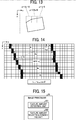
- FIG. 14 is a diagram illustrating an example of size detection (horizontal direction), according to the present embodiment. As illustrated in FIG. 14 , for representative positions in the vertical direction of the image, distances between the left side edge and the right side edge of the document 12, which is the subject, are obtained, and a size in the horizontal direction is calculated from the median value thereof and an inclination angle, which is calculated separately. In addition, a size in the vertical direction is calculated in substantially the same manner.
- the size information detected in this way is usable for error detection or image correction processing, which is described later.
- the error detection for example, in a case of scanning with a multifunction peripheral, when a size that is different from a document size set in advance by a user is detected, the user is notified to set a document of the correct size.
- the present embodiment with respect to the visible image or the invisible image, by detecting the feature amount of the document 12, which is the subject, and the background portion 13 from at least one of the visible image and the invisible image, information that is not obtainable from the visible image is obtainable from the invisible image, resulting in performing the stable edge detection between the document and the background regardless of the type of the document.
- the imaging unit 22 receives the visible light and the invisible light that are reflected from the document 12, which is the subject, and captures the visible image and the invisible image. This allows the imaging unit 22 to read an image with a simple configuration.
- the invisible light and the invisible image are the infrared light and the infrared image, respectively, the image is readable with a simple configuration.
- the second embodiment is different from the first embodiment in that the feature amount is extracted from each of the visible image and the invisible image, and selection or combination among the feature amounts extracted from both of the visible image and the invisible image are automatically performed.
- the description of the same parts as in the first embodiment will be omitted, and those different from the first embodiment will be described.
- the elements, functions, processes, and steps that are the same or substantially the same as those described in the first embodiment are denoted by the same reference numerals or step numbers, and redundant descriptions thereof are omitted below.
- FIG. 15 is a block diagram illustrating a functional configuration of an image processor according to the second embodiment.
- the image processor 20 includes a feature amount selecting/combining unit 202 in addition to the feature amount detection unit 201.
- the feature amount detection unit 201 detects, with respect to the visible image or the invisible image obtained by the imaging unit 22, the feature amount of the document 12, which is the subject, and the background portion 13, which is detected from at least one of the visible image and the invisible image.
- the feature amount selecting/combining unit 202 selects one among or combines the feature amounts each detected from a corresponding image, based on the feature amount of the document 12, which is the subject, and the background portion 13, which is detected from at least one of the visible image and the invisible image by the feature amount detection unit 201.
- the feature amount selecting/combining unit 202 automatically performs the selection processing described with reference to FIG. 6 .
- a targeted feature amount which is failed to be extracted by the visible image alone or the invisible image alone is obtainable by using the visible image and the invisible image in combination.
- FIG. 16 is a diagram illustrating OR processing performed on an edge (one or more edges, one or more edge portions) by the feature amount selecting/combining unit 202, according to the present embodiment.
- the feature amount selecting/combining unit 202 according to the present embodiment performs the OR processing on an edge when extracting, as the feature amount, the edge of the document 12, which is the subject.
- a portion where the edge is not able to be taken in one of the images is complemented by the other one of the images.
- an edge (edge portion) of the black region of the document is easy to be taken and an edge (edge portion) of the white region is difficult to be taken in the visible image.
- an edge (edge portion) of the white region of the document is easy to be taken and an edge (edge portion) of the black region is difficult to be taken in the invisible image.
- the edge detected from the invisible image may be referred to as a first edge
- the edge detected from the visible image may be referred to as a second edge.
- the feature amount selecting/combining unit 202 combines the edge (edge portion) of the black region in the visible image and the edge (edge portion) of the white region in the invisible image to extract the edge of the entire document that is not obtained by one of the images alone.
- the feature amount selecting/combining unit 202 performs the OR processing on the edges detected from the invisible image and the visible image to combine the edges. Accordingly, there is a portion where the edge is detectable in either the visible image or the invisible image, and thereby the edge between the document 12, which is the subject, and the background portion 13 is detectable in most of the portions of the edge, namely the number of edge detectable portions increases.
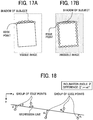
- FIG. 17A and FIG. 17B are diagrams illustrating how edges in the visible image and the invisible image appear, according to the present embodiment.
- a shadow of the document 12, which is the subject may be come out in the background of the visible image, and the edge is failed to be extracted linearly depending on a shape of the shadow. This may give an effect in detection accuracy of an inclination of the document 12, which is the subject.
- the edge extraction, itself is failed to be performed.
- the edge between the document 12, which is a subject and white, and the background portion 13 is easily extractable. Even in the invisible image, there may be a case where a shadow appears on the document 12, which is the subject. However, since the shadow is darker than the background, for example, when the edge is detected with a first order differential filter that filters in order "from a dark part to a bright part", the edge between the shadow and the document is obtainable, but not the edge between the shadow and the background.
- FIG. 18 is a diagram illustrating an example of a determination of the edge detection performed normally, according to the present embodiment.
- Criteria for "normally detect” may be that, for example, as illustrated in FIG. 18 , when the obtained edge point groups are regressed with a straight line, a difference by the least squares method is equal to or less than a threshold value, or an inclination angle of the straight line is equal to or less than a threshold value.
- the criteria for "normally detect” may include that the number of line equations normally determined is equal to or larger than a threshold value.
- the feature amount selecting/combining unit 202 sets, in edge selection processing (selection processing related to the edge), the edge detected from the invisible image in a case where the edge is detected normally from the invisible image and sets the edge detected from the visible image in a case where the edge is not detected normally from the invisible image. In this case, with the invisible image, the edge is more likely to be detected and the detection accuracy is improved.
- FIG. 19A, FIG. 19B, and FIG. 19C are diagrams illustrating an example of failure of the OR processing performed on edges, according to the present embodiment.
- the OR processing is performed on the visible image and the invisible image, there is a possibility that an untargeted edge is extracted.
- FIG. 19A to FIG. 19C when an edge is extracted between a shadow of the document 12, which is the subject, and the background portion 13 in the visible image, the shadow of the document 12, which is the subject, remains after the OR processing is performed, and this gives an effect on the calculation of an inclination of the document.
- the feature amount detection unit 201 performs the OR processing when the edge detection is not normally performed in both the visible image and the invisible image.
- the feature amount selecting/combining unit 202 performs the OR processing on the edge detected from the invisible image and the edge detected from the visible image in a case where neither the edge of the invisible image nor the edge of the visible image is not detected normally. How the edge appears may differ between the visible image and the invisible image due to a shadow of the document. Accordingly, the OR processing is performed when the edge is failed to be detected normally from each image.
- FIG. 20A and FIG. 20B are diagrams illustrating an example of a subject having a plurality of features mixed, according to the present embodiment. As illustrated in FIG. 20 , for example, with the document 12, which is the subject, having a plurality of features mixed, a lower part of the document 12, which is the subject, is extracted from the visible image, and an upper part of the document 12, which is the subject, is extracted from the invisible image.
- the feature amount of the document 12, which is the subject, and the background portion 13 is detected from at least one of the visible image and the invisible image, and the selection processing or the combination processing related the feature amount detected from each of the images is performed.
- the feature amount is automatically selected from one of the visible image and the invisible image, or the feature amount of the visible image and the feature amount of the invisible image are combined.
- the third embodiment is different from the first embodiment and the second embodiment in including an image correction unit that corrects an image of a subject.
- an image correction unit that corrects an image of a subject.
- the description of the same parts as in the first and second embodiments will be omitted, and those different from the first and second embodiments will be described.
- the elements, functions, processes, and steps that are the same or substantially the same as those described in the first and second embodiments are denoted by the same reference numerals or step numbers, and redundant descriptions thereof are omitted below.
- FIG. 21 is a block diagram illustrating a functional configuration of an image processor according to the third embodiment.
- FIG. 22 is a flowchart illustrating operation performed by the image processor according to the third embodiment.
- the image processor 20 includes an image correction unit 203 in addition to the feature amount detection unit 201 and the feature amount selecting/combining unit 202.
- the feature amount detection unit 201 detects, with respect to a visible image or an invisible image obtained by the imaging unit 22, a feature amount of the document 12, which is the subject, and the background portion 13, which is detected from at least one of the visible image and the invisible image (Step S1).
- the feature amount selecting/combining unit 202 selects one among or combines the feature amounts each of which is detected from one of the visible image and the invisible image (Step S2).
- the image correction unit 203 performs image correction for each of the visible image and the invisible image by using a result obtained by combination processing performed by the feature amount selecting/combining unit 202 (Step S3).
- An example of the image correction is given later.
- FIG. 23 is a diagram illustrating an example of correcting an inclination and a position of the subject, according to the present embodiment.
- the image correction unit 203 corrects the inclination and the position of the document 12, which is the subject, by the feature amount detected by the feature amount selecting/combining unit 202.
- the image correction unit 203 uses a method in which an inclination is obtained after the edge point groups, each of which is extracted from a side of the document 12, which is the subject, are regressed with a straight line, as described above, and then the entire image is rotated based on the obtained inclination.
- the image correction unit 203 uses a method in which a position (point) of an intersection of the regression lines of the edge point groups of the upper side and the left side of the document 12, which is the subject, is obtained, and then the point, which is the intersection, is moved to the origin.
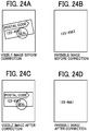
- FIG. 24A to FIG. 24D are diagrams illustrating examples of use of the invisible image, according to the present embodiment.
- OCR optical character recognition
- the document 12, which is the subject is corrected to be easily viewable.
- the OCR accuracy and the like improve.
- FIG. 25 is a diagram illustrating an example of correcting an inclination and a position of a subject and cutting out the subject, according to the present embodiment.
- the image correction unit 203 cuts out a region of the document 12, which is the subject, in a just size by combining the inclination correction and the position correction, which are described above. Even when the feature amount is not detected correctly and the inclination or the position is not corrected, the subject is able to be cut out, though the size is not the just size.
- FIG. 26 is a diagram illustrating an example of inclination correction, according to the present embodiment.
- consecutive pixels in the image are required to be collectively replaced, with equal to or more than a minimum width for the convenience of processing speed.
- instead of the inclination correction it may be desired to delete a region of the background portion 13 as much as possible.
- the image correction unit 203 may perform processing such as, if a rightmost edge point is identified, a region in the right side of the edge point is outside of the document 12, which is the subject, so that the region is deleted from the image.
- FIG. 27 is a diagram illustrating processing for identifying a rightmost edge point, according to the present embodiment.
- the edge extraction is able to be performed on only a part of the image due to an amount of memory
- information on a size in the vertical direction which may be obtained by, for example, sensor information in transferring the document, is enough for the processing.
- the image correction unit 203 calculates the rightmost edge point from the edge pixels in the region by using information including the inclination information.
- the image correction unit 203 deletes an unnecessary region of the background portion 13 by cutting out the region of the document 12, which is the subject.
- the image forming apparatus 100 such as a multifunction peripheral, there are effects obtained, for example, work performed by a user to input a size of the document 12, which is the subject, is reduced, the appearance of the image is improved, the storage area of the image storage destination is saved, and a size of the recording paper is reduced and the consumption of ink and toner is reduced in copying the image.
- the work of the user to input the document size is reduced (in particular, in a case of an irregular size).
- effects such as improving the appearance of the image, saving the storage area of the image storage destination, and reducing the size of the recording paper and reducing the consumption of ink and toner in copying the image are obtained.
- the image correction unit 203 corrects at least one of the visible image and the invisible image, resulting in improving the visibility of the image.
- the image processing apparatus is applied to an MFP having at least two of copying, printing, scanning, and facsimile functions.
- the image processing apparatus may be applied to any image forming apparatus such as for example, a copier, a printer, a scanner, or a facsimile machine.
- the image reading device 101 of the image forming apparatus 100 is applied as the image processing apparatus, but the present disclosure is not limited to this.
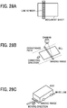
- the definition of the image processing apparatus is any apparatus or device that is able to acquire a reading level without reading as an image, such as a line sensor of the same magnification optical system (contact optical system: contact image sensor (CIS) type) illustrated in FIG. 28A .
- a device illustrated in FIG. 28A reads information on a plurality of lines by moving a line sensor or a document.
- the image processing apparatus is applicable to a bill conveying device as illustrated in FIG. 28B , a white line detection device of an automatic guided vehicle (AGV) as illustrated in FIG. 28C , and the like.
- AGV automatic guided vehicle
- a subject of the bill conveying device illustrated in FIG. 28B is a bill (a piece of paper money).
- a feature amount detected by the bill conveying device is used for correcting an image itself, for example. That is, the bill conveying device illustrated in FIG. 28B recognizes an inclination of the bill by edge detection, and performs skew correction using the recognized inclination.
- a subject of the white line detection device of the automatic guided vehicle illustrated in FIG. 28c is a white line.
- a feature amount output by the white line detection device of the automatic guided vehicle is usable for determining a moving direction of the automatic guided vehicle. That is, the white line detection device of the automatic guided vehicle recognizes an inclination of a white line region by edge detection and determines a moving direction of the automatic guided vehicle using the recognized inclination. Further, the white line detection device of the automatic guided vehicle is able to correct the moving direction according to a position or an orientation of the automatic guided vehicle in a later process. For example, the automatic guided vehicle is able to stop driving when a white line having a thickness different from a predetermined thickness is detected.
- the present disclosure may be implemented in any convenient form, for example using dedicated hardware, or a mixture of dedicated hardware and software.
- the present disclosure may be implemented as computer software implemented by one or more networked processing apparatuses.
- the processing apparatuses can comprise any suitably programmed apparatuses such as a general purpose computer, personal digital assistant, mobile telephone (such as a WAP or 3G-compliant phone) and so on. Since the present disclosure can be implemented as software, each and every aspect of the present disclosure thus encompasses computer software implementable on a programmable device.
- the computer software can be provided to the programmable device using any conventional carrier medium (carrier means).
- the carrier medium can comprise a transient carrier medium such as an electrical, optical, microwave, acoustic or radio frequency signal carrying the computer code.
- transient medium is a TCP/IP signal carrying computer code over an IP network, such as the Internet.
- the carrier medium can also comprise a storage medium for storing processor readable code such as a floppy disk, hard disk, CD ROM, magnetic tape device or solid state memory device.
Abstract
Description
- Embodiments of the present disclosure relate to a reading device, an image processing apparatus, and a method of detecting a feature amount.
- Conventionally, an image processing technique for detecting an edge between a document and a background from an image and correcting an inclination and a position of the document based on the detected edge between the document and the background is known.
-
JP-2014-053739-A - However, according to such a conventional art, although the infrared light low reflection portion is provided as the background, and edge detection of detecting the edge between the document and the background is performed based on the acquired infrared image, there is an issue that the edge detection is not successfully performed depending on a color of the document.
- In view of the above-described issue, an object of one or more embodiments of the present disclosure is to achieve stable edge detection of detecting an edge between a document and a background regardless of a type of the document.
- An exemplary embodiment of the present disclosure includes a reading device (101) including an illumination unit (2), an imaging unit (22), a background portion (13), and an image processor (20, 201). The illumination unit (2) irradiates visible light and invisible light to a subject. The imaging unit (22) receives the visible light and the invisible light, each of which is reflected from the subject, to capture a visible image and an invisible image. The background portion (13) is provided in an image capturing range of the imaging unit (22). The image processor (20, 201) detects a feature amount of the subject and the background portion (13) from at least one of the visible image and the invisible image.
- According to one or more embodiments of the present disclosure, there is an effect that stable edge detection of detecting an edge between a document and a background is able to be performed regardless of a type of the document.
- A more complete appreciation of the disclosure and many of the attendant advantages and features thereof can be readily obtained and understood from the following detailed description with reference to the accompanying drawings, wherein:
-
FIG. 1 is a view illustrating an exemplary configuration of an image forming apparatus according to one or more embodiments; -
FIG. 2 is a cross-sectional view exemplarily illustrating a structure of an image reading device according to one or more embodiments; -
FIG. 3 is a block diagram illustrating electrical connections of components of an image reading device according to one or more embodiments; -
FIG. 4 is a block diagram illustrating an example of a functional configuration of an image processor according to one or more embodiments; -
FIG. 5 is a diagram illustrating difference in spectral reflection characteristics depending on a medium in detection of a feature amount of a subject, according to one or more embodiments; -
FIG. 6A to FIG. 6C are diagrams illustrating difference in spectral reflection characteristics between a visible image and an invisible image depending on a paper type, according to one or more embodiments; -
FIG. 7 is a diagram illustrating an example in selecting a visible component as an extraction target for a feature amount, according to one or more embodiments; -
FIG. 8 is a diagram illustrating an example of spectral reflection characteristics when a background portion is an invisible light low reflection portion, according to one or more embodiments; -
FIG. 9A, FIG. 9B, and FIG. 9C are diagrams each illustrating an example of an invisible light low reflection portion, according to one or more embodiments; -
FIG. 10 is a diagram illustrating information obtained from one or more edges of a subject, according to one or more embodiments; -
FIG. 11A and FIG. 11B are diagrams each illustrating an example of a method of edge detection, according to one or more embodiments; -
FIG. 12A and FIG. 12B are diagrams each illustrating an example of a feature amount using one or more edges, according to one or more embodiments; -
FIG. 13 is a diagram illustrating selection of a line equation in a regression line equation, according one or more embodiments; -
FIG. 14 is a diagram illustrating an example of size detection (horizontal direction), according to one or more embodiments; -
FIG. 15 is a block diagram illustrating a functional configuration of an image processor according to one or more embodiments; -
FIG. 16 is a diagram illustrating OR processing performed on edges, according to one or more embodiments; -
FIG. 17A and FIG. 17B are diagrams illustrating how edges in a visible image and an invisible image appear, according to one or more embodiments; -
FIG. 18 is a diagram illustrating an example of a determination of an edge detection performed normally, according to one or more embodiments; -
FIG. 19A, FIG. 19B, and FIG. 19C are diagrams illustrating an example of failure of OR processing performed on an edge, according to one or more embodiments; -
FIG. 20A and FIG. 20B are diagrams illustrating an example of a subject having a plurality of features mixed, according to one or more embodiments; -
FIG. 21 is a block diagram illustrating a functional configuration of an image processor according to one or more embodiments; -
FIG. 22 is a flowchart illustrating operation performed by an image processor according to one or more embodiment; -
FIG. 23 is a diagram illustrating an example of correcting an inclination and a position of a subject, according to one or more embodiments; -
FIG. 24A to FIG. 24D are diagrams illustrating examples of use of an invisible image, according to one or more embodiments; -
FIG. 25 is a diagram illustrating an example of correcting an inclination and a position of a subject and cutting out the subject, according to one or more embodiments; -
FIG. 26 is a diagram illustrating an example of inclination correction, according to one or more embodiments; -
FIG. 27 is a diagram illustrating processing for identifying a rightmost edge point, according to one or more embodiments; and -
FIG. 28A to FIG. 28C are diagrams each illustrating a modified example of the image processing device, according to one or more embodiments. - The accompanying drawings are intended to depict example embodiments of the present disclosure and should not be interpreted to limit the scope thereof. The accompanying drawings are not to be considered as drawn to scale unless explicitly noted.
- The terminology used herein is for describing particular embodiments only and is not intended to be limiting of the present disclosure. As used herein, the singular forms "a", "an" and "the" are intended to include the plural forms as well, unless the context clearly indicates otherwise. It will be further understood that the terms "includes" and/or "including", when used in this specification, specify the presence of stated features, integers, steps, operations, elements, and/or components, but do not preclude the presence or addition of one or more other features, integers, steps, operations, elements, components, and/or groups thereof. In describing preferred embodiments illustrated in the drawings, specific terminology is employed for the sake of clarity. However, the disclosure of this patent specification is not intended to be limited to the specific terminology so selected, and it is to be understood that each specific element includes all technical equivalents that have the same function, operation in a similar manner, and achieve a similar result.
- Hereinafter, embodiments of a reading device, an image processing apparatus, and a method of detecting a feature amount are described in detail with reference to the attached drawings.
-
FIG. 1 is a view illustrating an exemplary configuration of animage forming apparatus 100 according to a first embodiment of the disclosure. InFIG. 1 , theimage forming apparatus 100, which serves as an image processing apparatus, is an apparatus generally referred to as a multifunction peripheral (MFP) that has at least two functions among a copy function, a printer function, a scanner function, and a facsimile function. - The
image forming apparatus 100 includes animage reading device 101 serving as a reading device, an automatic document feeder (ADF) 102, and animage forming device 103 provided below theimage reading device 101. Theimage forming device 103 is configured to form an image. In order to describe an internal configuration of theimage forming device 103,FIG. 1 illustrates the internal configuration of theimage forming device 103 from which an external cover is removed. - The
ADF 102 is a document supporter that positions, at a reading position, a document including an image to be read. TheADF 102 automatically feeds the document placed on a placement table to the reading position. Theimage reading device 101 reads the document fed by theADF 102 at a predetermined reading position. Theimage reading device 101 has, on a top surface, a contact glass that is the document supporter, on which a document is placed, and reads the document on the contact glass that is at the reading position. Specifically, theimage reading device 101 is a scanner including a light source, an optical system, and a solid-state imaging element such as a complementary metal oxide semiconductor (CMOS) image sensor inside, and reads, by the solid-state imaging element through the optical system, reflected light of the document, which is illuminated, or irradiated, by the light source. - The
image forming device 103 includes a manualfeed roller pair 104 for manually feeding a recording sheet, and a recordingsheet supply unit 107 for supplying the recording sheet. The recordingsheet supply unit 107 includes a mechanism for feeding out the recording sheet from multi-stage recordingpaper feed cassettes 107a. The recording sheet thus supplied is sent to asecondary transfer belt 112 via aregistration roller pair 108. - A
secondary transfer device 114 transfers a toner image from anintermediate transfer belt 113 onto the recording sheet conveyed on thesecondary transfer belt 112. - The
image forming device 103 also includes anoptical writing device 109, an image forming unit (for yellow (Y), magenta (M), cyan (C), and black (K)) 105 employing a tandem system, theintermediate transfer belt 113, and thesecondary transfer belt 112. Specifically, in an image forming process, theimage forming unit 105 renders an image written by theoptical writing device 109 as a toner image and forms the toner image on theintermediate transfer belt 113. - Specifically, the image forming unit (for Y, M, C, and K) 105 includes four photoconductor drums (Y, M, C, and K) in a rotatable manner, and
image forming elements 106 each including a charging roller, a developing device, a primary transfer roller, a cleaner unit, and a static eliminator around the respective photoconductor drums. Theimage forming element 106 functions on each photoconductor drum, and the image on the photoconductor drum is transferred onto theintermediate transfer belt 113 by each primary transfer roller. - The
intermediate transfer belt 113 is arranged to be stretched by a drive roller and a driven roller at a nip between each photoconductor drum and each primary transfer roller. The toner image primarily transferred onto theintermediate transfer belt 113 is secondarily transferred onto the recording sheet on thesecondary transfer belt 112 by a secondary transfer device as theintermediate transfer belt 113 runs. The recording sheet is conveyed to afixing device 110 as thesecondary transfer belt 112 runs, and the toner image is fixed as a color image on the recording sheet. Finally, the recording sheet is discharged onto an output tray disposed outside a housing of theimage forming apparatus 100. Note that, in a case of duplex printing, areverse assembly 111 reverses the front and back sides of the recording sheet and sends out the reversed recording sheet onto thesecondary transfer belt 112. - The
image forming device 103 is not limited to the one that forms an image by an electrophotographic method as described above. Theimage forming device 103 may be one that forms an image by an inkjet method. - Next, a description is given of the
image reading device 101. -
FIG. 2 is a cross-sectional view exemplarily illustrating a structure of theimage reading device 101 according to the present embodiment. As illustrated inFIG. 2 , theimage reading device 101 includes, in ahousing 11, asensor substrate 10 provided with an imaging unit (image sensor) 22, which is a solid-state imaging element, alens unit 8, afirst carriage 6, and asecond carriage 7. Thefirst carriage 6 includes alight source 2, which is a light emitting diode (LED), and amirror 3. Thesecond carriage 7 includesmirrors image reading device 101 is provided with acontact glass 1 on an upper surface. - The
light source 2 is configured as a light source for visible/invisible light. In the description, the invisible light is light having a wavelength equal to or less than 380 nm or equal to or more than 750 nm. That is, thelight source 2 is an illumination unit that irradiates a subject and abackground portion 13 with the visible light and the invisible light (for example, near infrared (NIR) light). - Further, the
image reading device 101 is provided with thebackground portion 13 that is a reference white board, on the upper surface. More specifically, thebackground portion 13 is provided on an opposite side to thelight source 2, which is the illumination unit, with respect to the subject, in an image capturing range of theimaging unit 22. - In a reading operation, the
image reading device 101 irradiates light upward from thelight source 2 while moving thefirst carriage 6 and thesecond carriage 7 from a standby position (home position) in a sub-scanning direction (direction A). Thefirst carriage 6 and thesecond carriage 7 cause reflected light from adocument 12, which is the subject, to be imaged on theimaging unit 22 via thelens unit 8. - Further, when the power is turned on, the
image reading device 101 reads reflected light from the reference white board (background board) 13 to set a reference. That is, theimage reading device 101 moves thefirst carriage 6 directly below the reference white board (background board) 13, turns on thelight source 2, and causes the reflected light from the referencewhite board 13 to be imaged on theimaging unit 22, thereby performing a gain adjustment. - The
imaging unit 22 images visible and invisible wavelength ranges. In theimaging unit 22, pixels that convert incident light level into electric signals are arranged. The pixels are arranged in a matrix, and the electric signals each of which is obtained from corresponding one of the pixels are transferred to a signal processing unit 222, which is arranged in a subsequent stage (seeFIG. 3 ), in a predetermined order at regular time intervals (pixel reading signal). A color filter that transmits light limited to having a specific wavelength is arranged on each pixel. In theimaging unit 22 according to the present embodiment, each signal obtained from a pixel group in which the same color filter is arranged is referred to as a channel. In addition, in the present embodiment, an image captured by theimaging unit 22 by irradiating visible light is referred to as a visible image, and an image captured by theimaging unit 22 by irradiating invisible light such as near infrared light is referred to as an invisible image. - Although an image reading device of a reduction optical system is applied as the
image reading device 101 of the present embodiment, no limitation is intended thereby. Alternatively, an equal magnification optical system (contact optical system: contact image sensor (CIS) type) may be used, for example. -
FIG. 3 is a block diagram illustrating electrical connections of components of theimage reading device 101 according to the present embodiment of the present disclosure. In addition to the imaging unit (image sensor) 22 and thelight source 2 described above, theimage reading device 101 includes animage processor 20, a controller 23, and alight source driver 24 as illustrated inFIG. 3 . The controller 23, which may be implemented by a processor such as a CPU that operates according a program stored in a memory, controls theimaging unit 22, theimage processor 20, and thelight source driver 24. Thelight source driver 24 drives thelight source 2 under control of the controller 23. - The
imaging unit 22 is a sensor for a reduction optical system, such as a CMOS image sensor, for example. Theimaging unit 22 includes a pixel unit 221 and the signal processing unit 222. - In the present embodiment, the
imaging unit 22 is described as having a four-line configuration as an example, but the configuration is not limited to the four-line configuration. In addition, a circuit configuration in a subsequent stage of the pixel unit 221 is not limited to the configuration illustrated inFIG. 3 . - The pixel unit 221 has pixel groups corresponding to four lines, in each of which a plurality of pixel circuits each being configured as a pixel is arranged in a matrix. The signal processing unit 222 processes a signal output from the pixel unit 221 as appropriate and transfers the signal to the
image processor 20 arranged in a subsequent stage. - The
image processor 20 performs various types of image processing on image data according to a purpose of use. -
FIG. 4 is a block diagram illustrating a functional configuration of theimage processor 20, according to the present embodiment of the disclosure. As illustrated inFIG. 4 , theimage processor 20 includes a featureamount detection unit 201. - The feature
amount detection unit 201 detects a feature amount of thedocument 12, which is the subject, with respect to the visible image or the invisible image obtained by theimaging unit 22. -
FIG. 5 is a diagram illustrating difference in spectral reflection characteristics depending on a medium in detection of the feature amount of the subject, according to the present embodiment. When theimaging unit 22 reads the reflected light from thedocument 12, which is the subject, the spectral reflection characteristics of thebackground portion 13 is different from the spectral reflection characteristics of thedocument 12, which is the subject, in general. In the example illustrated inFIG. 5 , thebackground portion 13 is downward to the right, and thedocument 12, which is the subject, is upward to the right. That is, an image obtained with the visible light has a feature different from an image obtained with the invisible light. Accordingly, the featureamount detection unit 201 sets to one of the visible image and the invisible image as an image to be detected (detection target) in advance, according to a type of thedocument 12, which is the subject, and a type of thebackground portion 13. This allows the featureamount detection unit 201 to easily obtain a targeted feature amount. -
FIG. 6A to FIG. 6C are diagrams illustrating difference in spectral reflection characteristics between the visible image and the invisible image depending on a paper type, according to the present embodiment of the disclosure. For example, according to the example illustrated inFIG. 6A, FIG. 6B, and FIG. 6C , when the visible image and the invisible image are compared with respect to a paper type A, the invisible image has larger difference in the spectral reflection characteristics from thebackground portion 13 than the visible image. Accordingly, in the case of the paper type A, the featureamount detection unit 201 sets the invisible image as the detection target for the feature amount. On the other hand, when comparing the visible image and the invisible image with respect to a paper type B, the visible image has larger difference in the spectral reflection characteristics from thebackground portion 13 than the invisible image. Accordingly, in the case of the paper type B, the featureamount detection unit 201 sets the visible image as the detection target for the feature amount. - A description is given below of selecting a visible component as an extraction target for the feature amount.
-
FIG. 7 is a diagram illustrating an example in selecting a visible component as an extraction target for the feature amount, according to the present embodiment. The light actually irradiated has a wide wavelength range, but in the example illustrated inFIG. 7 , a representative wavelength of each component is represented by a dotted line for simplicity. In addition, as an example, the near infrared light is used as the invisible light. - As illustrated in
FIG. 7 , when a reflectance of each visible component is compared with a reflectance (arrow X) of a component of the near infrared light in the difference between thebackground portion 13 and thedocument 12, which is the subject, a blue (B) component has the largest difference. Accordingly, by using the B component, the featureamount detection unit 201 make a difference in the feature amount between thedocument 12, which is the subject, and thebackground portion 13. - That is, the feature
amount detection unit 201 compares, with respect to the invisible light and the visible light, the differences in the spectral reflection characteristics between thebackground portion 13 and thedocument 12, which is the subject, and the selected visible component as the extraction target for the feature amount includes a component that has the largest difference in the spectral reflection characteristics from the invisible light among the visible light (a plurality of components of the visible light). In general, a feature amount of a green (G) component that has a wide wavelength range is often used from the visible image. However, in the case of the example illustrated inFIG. 7 , when the feature amounts in the visible range and the infrared range are used, the difference in the spectral reflection characteristics between the document and the background portion becomes large between the B component and an infrared component, so that edge detection is easier to be performed. - The feature
amount detection unit 201 is not limited to extracting, as the feature amount used as a visible component, the one from the B component alone, but the feature amount used as a visible component may include a part, which is a component having the largest component value among the RGB components, for example. - Further, when the
document 12, which is the subject, has variations in the spectral reflection characteristics, the featureamount detection unit 201 may determine a visible component to be selected as the extraction target for the feature amount by measuring a representative from the variations of thedocument 12, which is the subject, or taking an average of measurement results. - A description is given below of a case where the
background portion 13 is an invisible light low reflection portion. -
FIG. 8 is a diagram illustrating an example of spectral reflection characteristics when thebackground portion 13 is an invisible light low reflection portion, according to the present embodiment. As illustrated inFIG. 8 , thebackground portion 13 may be the invisible light low reflection portion that diffusely reflects the visible light and reflects the invisible light at a reflectance lower than that of the visible light. As a result, a remarkable difference in the spectral reflectance of thebackground portion 13 occurs between the visible image and the invisible image, thereby making a difference in the spectral reflectance between thedocument 12, which is the subject, and thebackground portion 13 as well. This facilitates the featureamount detection unit 201 to extract a targeted feature amount. -
FIG. 9A, FIG. 9B, and FIG. 9C are diagrams each illustrating an example of the invisible light low reflection portion, according to the present embodiment. The invisible light low reflection portion may be provided as the whole of thebackground portion 13 or as a part or a pattern of thebackground portion 13 as illustrated in FIG.FIG. 9A, FIG. 9B, or FIG. 9C . - As described above, the
background portion 13 has the invisible light low reflection portion that diffusely reflects the visible light and reflects the invisible light at a lower reflectance than that of the visible light, and accordingly, there is a remarkable difference in a read value of the background between the visible image and the invisible image, resulting in performing robust edge detection. - A description is given below of a case where the feature
amount detection unit 201 extracts an edge of thedocument 12, which is the subject, as a feature amount. -
FIG. 10 is a diagram illustrating information obtained from an edge (one or more edges, one or more edge portions) of the subject, according to the present embodiment. As illustrated inFIG. 10 , an edge is a boundary between thedocument 12, which is the subject, and thebackground portion 13. By detecting the edge, as illustrated inFIG. 10 , a position, an inclination, a size, and the like of thedocument 12, which is the subject, are recognizable. Then, from the position and the inclination of thedocument 12, which is the subject, an image may be corrected according to the position or the inclination of thedocument 12, which is the subject, in a subsequent processing stage. -
FIG. 11A and FIG. 11B are diagrams each illustrating an example of a method of the edge detection, according to the present embodiment. As a method of the edge detection, as illustrated inFIG. 11A , for example, a method of applying a first order differential filter to the entire image and binarizing each pixel based on whether a value of each pixel exceeds a predetermined threshold value or not is used. In the above-described method, depending on the threshold value, an edge in a horizontal direction appears as consecutive several pixels with respect to vertical (and vice versa). This is because the edge is blurred mainly due to the modulation transfer function (MTF) characteristics of the optical system. To deal with this, as illustrated inFIG. 11B , in order to take representative edge pixels for calculation of a regression line equation and for size detection, which are described later, for example, there is a method of selecting a central pixel of the consecutive pixels (Part a illustrated inFIG. 11 ). -
FIG. 12A and FIG. 12B are diagrams each illustrating an example of a feature amount using an edge (one or more edges, one or more edge portions), according to the present embodiment. The edge may not be extracted as a feature amount itself from the image, but the edge may be used to obtain the feature amount. Such examples include a regression line equation calculated from extracted edge point groups using the least squares method, and a region (a set of positions) inside the edges, as illustrated inFIG. 12A and FIG. 12B , respectively. As for the regression line equation, there is a method of obtaining a single line equation based on all edge information for each side. In addition to that, there is another method of dividing the edge into a plurality of regions to calculate a plurality of line equations and selecting a representative one among the plurality of line equations or combining ones among the plurality of line equations. In the latter method, as a method of deriving a final line equation, a straight line, of which the inclination has a median value, is obtained or an average value of the plurality of the line equations is obtained, for example. -
FIG. 13 is a diagram illustrating selection of a line equation in the regression line equation, according to the present embodiment. By dividing an edge into a plurality of regions to calculate the plurality of line equations and selecting a representative one or combining representative ones among the plurality of line equations, the inclination of thedocument 12, which is the subject, is correctly recognizable even in a case where a corner of thedocument 12, which is the subject, is missing, as illustrated inFIG. 13 . - As the processing described above, the feature
amount detection unit 201 extracts the one or more edges of thedocument 12, which is the subject, as a feature amount, thereby detecting the region of thedocument 12, which is the subject. - Next, a description is given of size detection of the
document 12, which is the subj ect. -
FIG. 14 is a diagram illustrating an example of size detection (horizontal direction), according to the present embodiment. As illustrated inFIG. 14 , for representative positions in the vertical direction of the image, distances between the left side edge and the right side edge of thedocument 12, which is the subject, are obtained, and a size in the horizontal direction is calculated from the median value thereof and an inclination angle, which is calculated separately. In addition, a size in the vertical direction is calculated in substantially the same manner. - The size information detected in this way is usable for error detection or image correction processing, which is described later. Regarding the error detection, for example, in a case of scanning with a multifunction peripheral, when a size that is different from a document size set in advance by a user is detected, the user is notified to set a document of the correct size.
- As described above, according to the present embodiment, with respect to the visible image or the invisible image, by detecting the feature amount of the
document 12, which is the subject, and thebackground portion 13 from at least one of the visible image and the invisible image, information that is not obtainable from the visible image is obtainable from the invisible image, resulting in performing the stable edge detection between the document and the background regardless of the type of the document. - In addition, the
imaging unit 22 receives the visible light and the invisible light that are reflected from thedocument 12, which is the subject, and captures the visible image and the invisible image. This allows theimaging unit 22 to read an image with a simple configuration. - In addition, since the invisible light and the invisible image are the infrared light and the infrared image, respectively, the image is readable with a simple configuration.
- A description is now given of a second embodiment.
- The second embodiment is different from the first embodiment in that the feature amount is extracted from each of the visible image and the invisible image, and selection or combination among the feature amounts extracted from both of the visible image and the invisible image are automatically performed. In the following description of the second embodiment, the description of the same parts as in the first embodiment will be omitted, and those different from the first embodiment will be described. In addition, in the description of the second embodiment, the elements, functions, processes, and steps that are the same or substantially the same as those described in the first embodiment are denoted by the same reference numerals or step numbers, and redundant descriptions thereof are omitted below.
-
FIG. 15 is a block diagram illustrating a functional configuration of an image processor according to the second embodiment. As illustrated inFIG. 15 , theimage processor 20 includes a feature amount selecting/combiningunit 202 in addition to the featureamount detection unit 201. - As described above, the feature
amount detection unit 201 detects, with respect to the visible image or the invisible image obtained by theimaging unit 22, the feature amount of thedocument 12, which is the subject, and thebackground portion 13, which is detected from at least one of the visible image and the invisible image. - The feature amount selecting/combining
unit 202 selects one among or combines the feature amounts each detected from a corresponding image, based on the feature amount of thedocument 12, which is the subject, and thebackground portion 13, which is detected from at least one of the visible image and the invisible image by the featureamount detection unit 201. - More specifically, the feature amount selecting/combining
unit 202 automatically performs the selection processing described with reference toFIG. 6 . As a result, with respect to thedocument 12, which is the subject, a targeted feature amount which is failed to be extracted by the visible image alone or the invisible image alone, is obtainable by using the visible image and the invisible image in combination. -
FIG. 16 is a diagram illustrating OR processing performed on an edge (one or more edges, one or more edge portions) by the feature amount selecting/combiningunit 202, according to the present embodiment. The feature amount selecting/combiningunit 202 according to the present embodiment performs the OR processing on an edge when extracting, as the feature amount, the edge of thedocument 12, which is the subject. - By performing the OR processing for each edge extracted from the invisible image and the visible image, a portion where the edge is not able to be taken in one of the images is complemented by the other one of the images. For example, as illustrated in
FIG. 16 , in a case of a document having a gradation, an edge (edge portion) of the black region of the document is easy to be taken and an edge (edge portion) of the white region is difficult to be taken in the visible image. On the other hand, an edge (edge portion) of the white region of the document is easy to be taken and an edge (edge portion) of the black region is difficult to be taken in the invisible image. In the description, the edge detected from the invisible image may be referred to as a first edge, and the edge detected from the visible image may be referred to as a second edge. - Accordingly, the feature amount selecting/combining
unit 202 combines the edge (edge portion) of the black region in the visible image and the edge (edge portion) of the white region in the invisible image to extract the edge of the entire document that is not obtained by one of the images alone. - In this way, the feature amount selecting/combining
unit 202 performs the OR processing on the edges detected from the invisible image and the visible image to combine the edges. Accordingly, there is a portion where the edge is detectable in either the visible image or the invisible image, and thereby the edge between thedocument 12, which is the subject, and thebackground portion 13 is detectable in most of the portions of the edge, namely the number of edge detectable portions increases. - Next, a description is given of giving priority to the edge detected from the invisible image.
-
FIG. 17A and FIG. 17B are diagrams illustrating how edges in the visible image and the invisible image appear, according to the present embodiment. As illustrated inFIG. 17A , a shadow of thedocument 12, which is the subject, may be come out in the background of the visible image, and the edge is failed to be extracted linearly depending on a shape of the shadow. This may give an effect in detection accuracy of an inclination of thedocument 12, which is the subject. On the other hand, in an area where there is no shadow in the visible image, when thedocument 12, which is the subject, is white, there is a high possibility that the edge extraction, itself, is failed to be performed. - As illustrated in
FIG. 17B , in the invisible image, especially when thebackground portion 13 includes an invisible light low reflection portion, the edge between thedocument 12, which is a subject and white, and thebackground portion 13 is easily extractable. Even in the invisible image, there may be a case where a shadow appears on thedocument 12, which is the subject. However, since the shadow is darker than the background, for example, when the edge is detected with a first order differential filter that filters in order "from a dark part to a bright part", the edge between the shadow and the document is obtainable, but not the edge between the shadow and the background. Alternatively, even when two types of first order differential filters are used to take the edges in order of both "from a dark part to a bright part" and "from a bright part to a dark part", if the brightness is close to that of thebackground portion 13, the edge between the shadow and thebackground portion 13 is not to be extracted. Accordingly, there is a high possibility that accuracy of the edge detection between thedocument 12, which is the subject, and thebackground portion 13 performed with the invisible image is higher than that performed with the visible image. Accordingly, the edge detection with the visible image may be performed when the edge detection with the invisible image is not performed normally. -
FIG. 18 is a diagram illustrating an example of a determination of the edge detection performed normally, according to the present embodiment. Criteria for "normally detect" may be that, for example, as illustrated inFIG. 18 , when the obtained edge point groups are regressed with a straight line, a difference by the least squares method is equal to or less than a threshold value, or an inclination angle of the straight line is equal to or less than a threshold value. In addition, in the case of selecting/combining among the plurality of line equations as described above, the criteria for "normally detect" may include that the number of line equations normally determined is equal to or larger than a threshold value. - In this way, the feature amount selecting/combining
unit 202 sets, in edge selection processing (selection processing related to the edge), the edge detected from the invisible image in a case where the edge is detected normally from the invisible image and sets the edge detected from the visible image in a case where the edge is not detected normally from the invisible image. In this case, with the invisible image, the edge is more likely to be detected and the detection accuracy is improved. - Next, a description is given of a case where the edge is not detected normally in both the visible image and the invisible image.
-
FIG. 19A, FIG. 19B, and FIG. 19C are diagrams illustrating an example of failure of the OR processing performed on edges, according to the present embodiment. When the OR processing is performed on the visible image and the invisible image, there is a possibility that an untargeted edge is extracted. For example, as illustrated inFIG. 19A to FIG. 19C , when an edge is extracted between a shadow of thedocument 12, which is the subject, and thebackground portion 13 in the visible image, the shadow of thedocument 12, which is the subject, remains after the OR processing is performed, and this gives an effect on the calculation of an inclination of the document. However, since there is an advantage that the number of edge detectable portions increases in a case of performing the OR processing, as described above, the featureamount detection unit 201 performs the OR processing when the edge detection is not normally performed in both the visible image and the invisible image. - As described above, the feature amount selecting/combining
unit 202 performs the OR processing on the edge detected from the invisible image and the edge detected from the visible image in a case where neither the edge of the invisible image nor the edge of the visible image is not detected normally. How the edge appears may differ between the visible image and the invisible image due to a shadow of the document. Accordingly, the OR processing is performed when the edge is failed to be detected normally from each image. -
FIG. 20A and FIG. 20B are diagrams illustrating an example of a subject having a plurality of features mixed, according to the present embodiment. As illustrated inFIG. 20 , for example, with thedocument 12, which is the subject, having a plurality of features mixed, a lower part of thedocument 12, which is the subject, is extracted from the visible image, and an upper part of thedocument 12, which is the subject, is extracted from the invisible image. - As described above, according to the present embodiment, with respect to the visible image or the invisible image, the feature amount of the
document 12, which is the subject, and thebackground portion 13 is detected from at least one of the visible image and the invisible image, and the selection processing or the combination processing related the feature amount detected from each of the images is performed. As a result, the feature amount is automatically selected from one of the visible image and the invisible image, or the feature amount of the visible image and the feature amount of the invisible image are combined. - A description is now given of a third embodiment.
- The third embodiment is different from the first embodiment and the second embodiment in including an image correction unit that corrects an image of a subject. In the following description of the third embodiment, the description of the same parts as in the first and second embodiments will be omitted, and those different from the first and second embodiments will be described. In addition, in the description of the third embodiment, the elements, functions, processes, and steps that are the same or substantially the same as those described in the first and second embodiments are denoted by the same reference numerals or step numbers, and redundant descriptions thereof are omitted below.
-
FIG. 21 is a block diagram illustrating a functional configuration of an image processor according to the third embodiment.FIG. 22 is a flowchart illustrating operation performed by the image processor according to the third embodiment. As illustrated inFIG. 21 , theimage processor 20 includes animage correction unit 203 in addition to the featureamount detection unit 201 and the feature amount selecting/combiningunit 202. - As illustrated in
FIG. 22 , the featureamount detection unit 201 detects, with respect to a visible image or an invisible image obtained by theimaging unit 22, a feature amount of thedocument 12, which is the subject, and thebackground portion 13, which is detected from at least one of the visible image and the invisible image (Step S1). - As illustrated in
FIG. 22 , based on the feature amount of thedocument 12, which is the subject, and thebackground portion 13, which is detected from at least one of the visible image and the invisible image by the featureamount detection unit 201, the feature amount selecting/combiningunit 202 selects one among or combines the feature amounts each of which is detected from one of the visible image and the invisible image (Step S2). - As illustrated in
FIG. 22 , theimage correction unit 203 performs image correction for each of the visible image and the invisible image by using a result obtained by combination processing performed by the feature amount selecting/combining unit 202 (Step S3). An example of the image correction is given later. -
FIG. 23 is a diagram illustrating an example of correcting an inclination and a position of the subject, according to the present embodiment. In the example illustrated inFIG. 23 , theimage correction unit 203 corrects the inclination and the position of thedocument 12, which is the subject, by the feature amount detected by the feature amount selecting/combiningunit 202. - Regarding the correction of the inclination of the
document 12, which is the subject, theimage correction unit 203 uses a method in which an inclination is obtained after the edge point groups, each of which is extracted from a side of thedocument 12, which is the subject, are regressed with a straight line, as described above, and then the entire image is rotated based on the obtained inclination. - Regarding the correction of a position of the
document 12, which is the subject, theimage correction unit 203 uses a method in which a position (point) of an intersection of the regression lines of the edge point groups of the upper side and the left side of thedocument 12, which is the subject, is obtained, and then the point, which is the intersection, is moved to the origin. -
FIG. 24A to FIG. 24D are diagrams illustrating examples of use of the invisible image, according to the present embodiment. By correcting an image based on a result obtained by the combination processing performed by the feature amount selecting/combiningunit 202, effects including improvement in visibility of pictures or characters in a document region are obtained. In addition, the reflectance of the invisible component is remarkably different from that of the visible component depending on the coloring material, and as a result, colors may be skipped (diluted) to be removed as illustrated inFIG. 24B and FIG. 24D . By utilizing skipping the colors, processing of optical character recognition (OCR) or the like may be performed in a subsequent processing stage, accordingly. Therefore, there is an advantage that correcting the invisible image in addition to the visible image contributes to improve OCR accuracy. - As described above, by correcting the inclination and the position of the
document 12, which is the subject, based on a result of the edge detection, thedocument 12, which is the subject, is corrected to be easily viewable. In addition, there is a possibility that the OCR accuracy and the like improve. -
FIG. 25 is a diagram illustrating an example of correcting an inclination and a position of a subject and cutting out the subject, according to the present embodiment. As illustrated inFIG. 25 , theimage correction unit 203 cuts out a region of thedocument 12, which is the subject, in a just size by combining the inclination correction and the position correction, which are described above. Even when the feature amount is not detected correctly and the inclination or the position is not corrected, the subject is able to be cut out, though the size is not the just size. -
FIG. 26 is a diagram illustrating an example of inclination correction, according to the present embodiment. In a case of image processing performed by hardware, as an example in which the inclination correction is failed to be performed, as illustrated inFIG. 26 , consecutive pixels in the image are required to be collectively replaced, with equal to or more than a minimum width for the convenience of processing speed. However, it is difficult to correct an inclination when the inclination is too large. In such a case, instead of the inclination correction, it may be desired to delete a region of thebackground portion 13 as much as possible. - In this case, for example, the
image correction unit 203 may perform processing such as, if a rightmost edge point is identified, a region in the right side of the edge point is outside of thedocument 12, which is the subject, so that the region is deleted from the image. -
FIG. 27 is a diagram illustrating processing for identifying a rightmost edge point, according to the present embodiment. Even in a case where the edge extraction is able to be performed on only a part of the image due to an amount of memory, information on a size in the vertical direction, which may be obtained by, for example, sensor information in transferring the document, is enough for the processing. In this case, as illustrated inFIG. 27 , theimage correction unit 203 calculates the rightmost edge point from the edge pixels in the region by using information including the inclination information. The same applies to cases of an uppermost edge, a leftmost edge, and a lowermost edge, in addition to the rightmost edge. - The
image correction unit 203 deletes an unnecessary region of thebackground portion 13 by cutting out the region of thedocument 12, which is the subject. As a result, in theimage forming apparatus 100 such as a multifunction peripheral, there are effects obtained, for example, work performed by a user to input a size of thedocument 12, which is the subject, is reduced, the appearance of the image is improved, the storage area of the image storage destination is saved, and a size of the recording paper is reduced and the consumption of ink and toner is reduced in copying the image. - As described above, by automatically detecting and cutting out the size of the
document 12, which is the subject, from the image based on the edge, the work of the user to input the document size is reduced (in particular, in a case of an irregular size). In addition, effects such as improving the appearance of the image, saving the storage area of the image storage destination, and reducing the size of the recording paper and reducing the consumption of ink and toner in copying the image are obtained. - As described above, according to the present embodiment, the
image correction unit 203 corrects at least one of the visible image and the invisible image, resulting in improving the visibility of the image. - Note that in the embodiments described above, the image processing apparatus is applied to an MFP having at least two of copying, printing, scanning, and facsimile functions. Alternatively, the image processing apparatus may be applied to any image forming apparatus such as for example, a copier, a printer, a scanner, or a facsimile machine.
- In each of the above embodiments, the
image reading device 101 of theimage forming apparatus 100 is applied as the image processing apparatus, but the present disclosure is not limited to this. The definition of the image processing apparatus is any apparatus or device that is able to acquire a reading level without reading as an image, such as a line sensor of the same magnification optical system (contact optical system: contact image sensor (CIS) type) illustrated inFIG. 28A . A device illustrated inFIG. 28A reads information on a plurality of lines by moving a line sensor or a document. - Further, the image processing apparatus is applicable to a bill conveying device as illustrated in
FIG. 28B , a white line detection device of an automatic guided vehicle (AGV) as illustrated inFIG. 28C , and the like. - A subject of the bill conveying device illustrated in
FIG. 28B is a bill (a piece of paper money). A feature amount detected by the bill conveying device is used for correcting an image itself, for example. That is, the bill conveying device illustrated inFIG. 28B recognizes an inclination of the bill by edge detection, and performs skew correction using the recognized inclination. - A subject of the white line detection device of the automatic guided vehicle illustrated in
FIG. 28c is a white line. A feature amount output by the white line detection device of the automatic guided vehicle is usable for determining a moving direction of the automatic guided vehicle. That is, the white line detection device of the automatic guided vehicle recognizes an inclination of a white line region by edge detection and determines a moving direction of the automatic guided vehicle using the recognized inclination. Further, the white line detection device of the automatic guided vehicle is able to correct the moving direction according to a position or an orientation of the automatic guided vehicle in a later process. For example, the automatic guided vehicle is able to stop driving when a white line having a thickness different from a predetermined thickness is detected. - Any one of the above-described operations may be performed in various other ways, for example, in an order different from the one described above.
- The present disclosure may be implemented in any convenient form, for example using dedicated hardware, or a mixture of dedicated hardware and software. The present disclosure may be implemented as computer software implemented by one or more networked processing apparatuses. The processing apparatuses can comprise any suitably programmed apparatuses such as a general purpose computer, personal digital assistant, mobile telephone (such as a WAP or 3G-compliant phone) and so on. Since the present disclosure can be implemented as software, each and every aspect of the present disclosure thus encompasses computer software implementable on a programmable device. The computer software can be provided to the programmable device using any conventional carrier medium (carrier means). The carrier medium can comprise a transient carrier medium such as an electrical, optical, microwave, acoustic or radio frequency signal carrying the computer code. An example of such a transient medium is a TCP/IP signal carrying computer code over an IP network, such as the Internet. The carrier medium can also comprise a storage medium for storing processor readable code such as a floppy disk, hard disk, CD ROM, magnetic tape device or solid state memory device.
- Although the embodiments of the disclosure have been described and illustrated above, such description is not intended to limit the disclosure to the illustrated embodiments. Numerous additional modifications and variations are possible in light of the above teachings. It is therefore to be understood that within the scope of the appended claims, the embodiments may be practiced otherwise than as specifically described herein. For example, elements and/or features of different illustrative embodiments may be combined with each other and/or substituted for each other within the scope of this disclosure and appended claims.
Claims (15)
- A reading device (101), comprising:an illumination unit (2) that irradiates visible light and invisible light to a subject;an imaging unit (22) configured to receive the visible light and the invisible light, each of which is reflected from the subject, to capture a visible image and an invisible image;a background portion (13) provided in an image capturing range of the imaging unit (22); andan image processor (20, 201) configured to detect a feature amount of the subject and the background portion (13) from at least one of the visible image or the invisible image.
- The reading device (101), according to claim 1,
wherein the illumination unit (2) irradiates infrared light as the invisible light, and
wherein the imaging unit (22) captures an infrared image as the invisible image. - The reading device (101), according to any one of claims 1 and 2,
wherein the image processor (20, 201, 202) detects the feature amount of the subject and the background portion (13) from at least one of the visible image or the invisible image, and performs selection processing or combination processing depending on at least one of the feature amount detected from the visible image or the feature amount detected from the invisible image. - The reading device (101), according to any one of claims 1 to 3,
wherein the image processor (20, 201) compares, with respect to the invisible light and the visible light, differences in spectral reflection characteristics between the background portion (13) and the subject, and
the feature amount detected from the visible image including a component having the largest difference from the invisible light among a plurality of components of the visible light. - The reading device (101), according to any one of claims 1 to 4,
wherein the background portion (13) includes an invisible light low reflection portion that diffusely reflects the visible light and reflects the invisible light at a reflectance lower than the reflectance of the visible light. - The reading device (101), according to any one of claims 3 to 5,
wherein the image processor (20, 201) detects, as the feature amount, an edge of the subject, the edge being at least one of a first edge that is detected from the invisible image or a second edge that is detected from the visible image. - The reading device (101), according to claim 6,
wherein the image processor (20, 202) performs OR processing on the first edge detected from the invisible image and the second edge detected from the visible image to combine the first edge and second edge. - The reading device (101), according to claim 6,
wherein, in a case where the first edge is detected normally from the invisible image, the image processor (20, 202) selects the first edge,
wherein, in a case where the first edge is detected normally from the invisible image, the image processor (20, 202) selects the second edge. - The reading device (101), according to claim 6,
wherein, in a case where the image processor (20, 201) fails to normally detect the first edge from the invisible image and the second edge from the visible image, the image processor (20, 202) performs OR processing on the first edge and the second edge to combine the first edge and second edge. - The reading device (101), according to any one of claims 6 to 9,
wherein the image processor (20, 201) detects a size of the subject based on the edge. - The reading device (101), according to any one of claims 6 to 10,
wherein the image processor (20, 203) corrects an inclination and a position of the subject based on the edge. - The reading device (101), according to any one of claims 6 to 11,
wherein the image processor (20, 203) cuts out the subject based on the edge. - The reading device (101), according to any one of claims 1 to 11,
wherein the image processor (20, 203) corrects at least one of the visible image or the invisible image. - An image processing apparatus (100), comprising:the reading device (101) according to any one of claims 1 to 13; andan image forming device (103) provided below the reading device (101) and configured to form an image.
- A method of detecting a feature amount comprising
detecting (S1, S2, S3) a feature amount of a subject and a background portion from at least one of a visible image or an invisible image, each of the visible image and the invisible image being captured by an imaging unit receiving visible light and invisible light that is irradiated from a light source and reflected from the subject, the background portion being provided in an image capturing range of the imaging unit.
Applications Claiming Priority (1)
| Application Number | Priority Date | Filing Date | Title |
|---|---|---|---|
| JP2020038264A JP2021141467A (en) | 2020-03-05 | 2020-03-05 | Reading device, image processing device, and feature amount detection method |
Publications (2)
| Publication Number | Publication Date |
|---|---|
| EP3876509A1 true EP3876509A1 (en) | 2021-09-08 |
| EP3876509B1 EP3876509B1 (en) | 2024-04-24 |
Family
ID=74758661
Family Applications (1)
| Application Number | Title | Priority Date | Filing Date |
|---|---|---|---|
| EP21159319.9A Active EP3876509B1 (en) | 2020-03-05 | 2021-02-25 | Reading device, image processing apparatus, and method of detecting feature amount |
Country Status (3)
| Country | Link |
|---|---|
| US (1) | US11695892B2 (en) |
| EP (1) | EP3876509B1 (en) |
| JP (1) | JP2021141467A (en) |
Families Citing this family (3)
| Publication number | Priority date | Publication date | Assignee | Title |
|---|---|---|---|---|
| JP2022110367A (en) | 2021-01-18 | 2022-07-29 | 株式会社リコー | Fraud confirmation assist device and fraud confirmation method |
| JP2023042893A (en) * | 2021-09-15 | 2023-03-28 | 株式会社リコー | Image processing apparatus, reading system, image formation system and feature amount detection method |
| US20230308597A1 (en) * | 2022-03-23 | 2023-09-28 | Ayumu HASHIMOTO | Image processing apparatus, scanner, image forming apparatus, data management system, and image processing method |
Citations (3)
| Publication number | Priority date | Publication date | Assignee | Title |
|---|---|---|---|---|
| EP2706511A1 (en) * | 2012-09-06 | 2014-03-12 | Kabushiki Kaisha Toshiba | Image reading apparatus and sheet processing apparatus |
| WO2016018395A1 (en) * | 2014-07-31 | 2016-02-04 | Hewlett-Packard Development Company, L.P. | Document region detection |
| EP3609171A1 (en) * | 2018-08-10 | 2020-02-12 | Ricoh Company, Ltd. | Reading device, image forming apparatus including same, and reading method |
Family Cites Families (61)
| Publication number | Priority date | Publication date | Assignee | Title |
|---|---|---|---|---|
| US7684095B2 (en) * | 2004-09-27 | 2010-03-23 | Lexmark International, Inc. | Scanning apparatus having an ultraviolet light source |
| JP4565567B2 (en) | 2006-02-07 | 2010-10-20 | 株式会社リコー | Analog signal buffer, analog signal processing system, image reading apparatus, and image forming apparatus |
| JP4699417B2 (en) | 2007-04-16 | 2011-06-08 | 株式会社リコー | Analog processing circuit, analog integrated circuit device, image reading device, and image forming device |
| JP5444795B2 (en) | 2008-07-29 | 2014-03-19 | 株式会社リコー | Image reading apparatus, image forming apparatus, amplitude adjusting method, and computer program |
| JP5206423B2 (en) | 2009-01-07 | 2013-06-12 | 株式会社リコー | Image reading apparatus, image forming apparatus, and sample / hold control method |
| JP5326911B2 (en) | 2009-07-30 | 2013-10-30 | 株式会社リコー | Spread spectrum clock generator, circuit device, image reading device, image forming device, and spread spectrum clock generation method |
| JP5454019B2 (en) | 2009-09-02 | 2014-03-26 | 株式会社リコー | Photoelectric conversion element, sensor control circuit, image reading apparatus, and image forming apparatus |
| JP5476876B2 (en) | 2009-09-11 | 2014-04-23 | 株式会社リコー | Sensor driving circuit, driver device, image reading device, and image forming device |
| JP2011222360A (en) | 2010-04-12 | 2011-11-04 | Ricoh Co Ltd | Light source driving device, image processing device, image reading device, and image forming device |
| JP5724463B2 (en) | 2011-03-03 | 2015-05-27 | 株式会社リコー | Signal processing circuit, image reading apparatus, and image forming apparatus |
| JP5842350B2 (en) | 2011-03-18 | 2016-01-13 | 株式会社リコー | LIGHT SOURCE CONTROL DEVICE, LIGHT SOURCE CONTROL METHOD, IMAGE READING DEVICE, AND IMAGE FORMING DEVICE |
| JP6226508B2 (en) | 2011-09-13 | 2017-11-08 | 株式会社リコー | Image reading apparatus, image forming apparatus, and image reading method |
| JP6051654B2 (en) | 2012-07-25 | 2016-12-27 | 株式会社リコー | Image reading apparatus and image forming apparatus |
| JP6146015B2 (en) | 2013-01-18 | 2017-06-14 | 株式会社リコー | Photoelectric conversion element, image reading apparatus, and image forming apparatus |
| JP6127536B2 (en) | 2013-01-24 | 2017-05-17 | 株式会社リコー | Image reading apparatus, image forming apparatus, and image reading method |
| JP6149408B2 (en) | 2013-01-29 | 2017-06-21 | 株式会社リコー | Solid-state imaging device, image reading apparatus, and image forming apparatus |
| JP6205885B2 (en) | 2013-06-18 | 2017-10-04 | 株式会社リコー | Photoelectric conversion element, image reading apparatus, image forming apparatus, and image reading method |
| JP6383143B2 (en) | 2013-10-08 | 2018-08-29 | 株式会社リコー | Imaging device, image reading apparatus, image forming apparatus, and imaging method |
| JP6287058B2 (en) | 2013-10-24 | 2018-03-07 | 株式会社リコー | Photoelectric conversion element for reduction optical system, image reading apparatus, image forming apparatus, and image reading method |
| JP6225682B2 (en) | 2013-12-11 | 2017-11-08 | 株式会社リコー | Image sensor, image reading apparatus, and image forming apparatus |
| JP6281304B2 (en) | 2014-02-04 | 2018-02-21 | 株式会社リコー | Image sensor, image reading apparatus, and image forming apparatus |
| JP2015165626A (en) | 2014-03-03 | 2015-09-17 | 株式会社リコー | Document reading device and image forming apparatus |
| JP6519997B2 (en) | 2014-07-04 | 2019-05-29 | 株式会社リコー | PHOTOELECTRIC CONVERSION ELEMENT, IMAGE READER, AND IMAGE FORMING APPARATUS |
| JP6451104B2 (en) | 2014-07-04 | 2019-01-16 | 株式会社リコー | Photoelectric conversion element, image reading apparatus, image forming apparatus, and signal control method |
| JP6379794B2 (en) | 2014-07-24 | 2018-08-29 | 株式会社リコー | Image processing apparatus, image processing method, and image processing system |
| JP6549366B2 (en) | 2014-09-19 | 2019-07-24 | 株式会社リコー | PHOTOELECTRIC CONVERSION ELEMENT, IMAGE READER, AND IMAGE FORMING APPARATUS |
| JP6612492B2 (en) | 2014-10-16 | 2019-11-27 | 株式会社リコー | Photoelectric conversion element, image reading apparatus, and image forming apparatus |
| JP6519142B2 (en) | 2014-10-28 | 2019-05-29 | 株式会社リコー | Processing apparatus, image reading apparatus, and image forming apparatus |
| JP6432332B2 (en) | 2014-12-15 | 2018-12-05 | 株式会社リコー | Photoelectric conversion element, image reading apparatus, and image forming apparatus |
| US10106353B2 (en) * | 2015-01-29 | 2018-10-23 | Ricoh Company, Limited | Edge detection device, image forming apparatus, and edge detection method |
| JP6544070B2 (en) | 2015-06-16 | 2019-07-17 | 株式会社リコー | PHOTOELECTRIC CONVERSION ELEMENT, IMAGE READER, AND IMAGE FORMING APPARATUS |
| US9973659B2 (en) | 2015-07-13 | 2018-05-15 | Ricoh Company, Ltd. | Imaging element, image reading device, image forming apparatus, and imaging method |
| JP6790752B2 (en) | 2015-11-20 | 2020-11-25 | 株式会社リコー | Image reader, image forming device and image reading method |
| JP6682832B2 (en) | 2015-12-03 | 2020-04-15 | 株式会社リコー | Photoelectric conversion element, image reading device, image forming device, and image reading method |
| JP6668728B2 (en) | 2015-12-14 | 2020-03-18 | 株式会社リコー | Photoelectric conversion element, image reading device, and image forming device |
| JP2017126833A (en) | 2016-01-12 | 2017-07-20 | 株式会社リコー | Photoelectric conversion element, image reading apparatus, image forming apparatus, and image reading method |
| JP6728750B2 (en) | 2016-02-22 | 2020-07-22 | 株式会社リコー | Image reading apparatus, image forming apparatus, document image display method and program |
| JP6772493B2 (en) | 2016-03-14 | 2020-10-21 | 株式会社リコー | Image processing equipment, image processing methods and programs |
| JP6699305B2 (en) | 2016-04-07 | 2020-05-27 | 株式会社リコー | Signal processing device, photoelectric conversion element, image reading device, image forming device, and signal processing method |
| US10182177B2 (en) | 2016-04-15 | 2019-01-15 | Ricoh Company, Ltd. | Signal processing device, image scanning device, image forming apparatus, and method of controlling the same |
| JP6822096B2 (en) | 2016-11-24 | 2021-01-27 | 株式会社リコー | Photoelectric conversion device, photoelectric conversion method and image forming device |
| JP6880709B2 (en) | 2016-12-20 | 2021-06-02 | 株式会社リコー | Photoelectric conversion device, photoelectric conversion method and image forming device |
| US10542184B2 (en) | 2017-01-25 | 2020-01-21 | Ricoh Company, Ltd. | Photoelectric conversion device, defective pixel determining method, image forming apparatus, and recording medium |
| WO2018211588A1 (en) * | 2017-05-16 | 2018-11-22 | オリンパス株式会社 | Image capture device, image capture method, and program |
| JP6946983B2 (en) | 2017-11-30 | 2021-10-13 | 株式会社リコー | Position detection device, image reader, image forming device, program and position detection method |
| JP7056176B2 (en) | 2018-01-26 | 2022-04-19 | 株式会社リコー | Position detection device, image forming device, and position detection method |
| JP7159568B2 (en) | 2018-02-23 | 2022-10-25 | 株式会社リコー | Photoelectric conversion device, image reading device, and image forming device |
| JP7010131B2 (en) | 2018-04-24 | 2022-01-26 | 株式会社リコー | Color inspection equipment, image forming equipment, color inspection methods and programs |
| JP7081286B2 (en) | 2018-04-27 | 2022-06-07 | 株式会社リコー | Readers, image forming devices, information detection methods, and programs |
| CN110830670A (en) | 2018-08-10 | 2020-02-21 | 株式会社理光 | Reading device, image forming apparatus, authentication system, and reading method |
| JP7155737B2 (en) | 2018-08-10 | 2022-10-19 | 株式会社リコー | Image processing device, image processing system, program and image processing method |
| JP7115206B2 (en) | 2018-10-11 | 2022-08-09 | 株式会社リコー | Document size detection device, image reading device, image forming device, and document size detection method |
| JP7183682B2 (en) | 2018-10-12 | 2022-12-06 | 株式会社リコー | Reading device, image reading device, image forming device, and reading method |
| JP7131287B2 (en) | 2018-10-15 | 2022-09-06 | 株式会社リコー | Document size detection device, image reading device, image forming device, and document size detection method |
| JP7196540B2 (en) | 2018-10-31 | 2022-12-27 | 株式会社リコー | Sheet material reading device, document reading device and image forming device |
| JP7196644B2 (en) | 2019-01-30 | 2022-12-27 | 株式会社リコー | TILT DETECTION DEVICE, READING DEVICE, IMAGE PROCESSING DEVICE, AND TILT DETECTION METHOD |
| JP7131415B2 (en) | 2019-01-31 | 2022-09-06 | 株式会社リコー | TILT DETECTION DEVICE, READING DEVICE, IMAGE PROCESSING DEVICE, AND TILT DETECTION METHOD |
| JP7196698B2 (en) | 2019-03-11 | 2022-12-27 | 株式会社リコー | Image processing device, image processing method, and image processing program |
| JP7211238B2 (en) | 2019-04-16 | 2023-01-24 | 株式会社リコー | Edge detection device, tilt correction device, reading device, image processing device, and edge detection method |
| JP7310354B2 (en) | 2019-06-25 | 2023-07-19 | 株式会社リコー | Image processing device, image forming device and image processing method |
| JP7392302B2 (en) | 2019-06-25 | 2023-12-06 | 株式会社リコー | Image processing device, image forming device, and image processing method |
-
2020
- 2020-03-05 JP JP2020038264A patent/JP2021141467A/en active Pending
-
2021
- 2021-01-29 US US17/161,704 patent/US11695892B2/en active Active
- 2021-02-25 EP EP21159319.9A patent/EP3876509B1/en active Active
Patent Citations (4)
| Publication number | Priority date | Publication date | Assignee | Title |
|---|---|---|---|---|
| EP2706511A1 (en) * | 2012-09-06 | 2014-03-12 | Kabushiki Kaisha Toshiba | Image reading apparatus and sheet processing apparatus |
| JP2014053739A (en) | 2012-09-06 | 2014-03-20 | Toshiba Corp | Image reader and paper sheet processing device |
| WO2016018395A1 (en) * | 2014-07-31 | 2016-02-04 | Hewlett-Packard Development Company, L.P. | Document region detection |
| EP3609171A1 (en) * | 2018-08-10 | 2020-02-12 | Ricoh Company, Ltd. | Reading device, image forming apparatus including same, and reading method |
Also Published As
| Publication number | Publication date |
|---|---|
| EP3876509B1 (en) | 2024-04-24 |
| JP2021141467A (en) | 2021-09-16 |
| US11695892B2 (en) | 2023-07-04 |
| US20210281712A1 (en) | 2021-09-09 |
Similar Documents
| Publication | Publication Date | Title |
|---|---|---|
| EP3876509B1 (en) | Reading device, image processing apparatus, and method of detecting feature amount | |
| JP7211238B2 (en) | Edge detection device, tilt correction device, reading device, image processing device, and edge detection method | |
| US10484559B2 (en) | Control device for controlling image processing system, image forming apparatus, image reading apparatus, control method, and computer-readable recording medium | |
| JP7131415B2 (en) | TILT DETECTION DEVICE, READING DEVICE, IMAGE PROCESSING DEVICE, AND TILT DETECTION METHOD | |
| US8976414B2 (en) | Image processing method, image processing apparatus and image forming apparatus including the same, image reading apparatus, and recording medium | |
| JP6537699B2 (en) | Image reading apparatus, control method and control program | |
| US11457116B2 (en) | Image processing apparatus and image reading method | |
| US10574856B2 (en) | Image reading apparatus with reference surface to generate reference data for shading correction, and related image forming apparatus and method | |
| US11582362B2 (en) | Image reading apparatus comprising a processor that detects an abnormal pixel, and outputs an image obtained by a first processing or second processing based on if character recognition processing of a character obtained by first processing is the same as the character obtained by the second processing | |
| US20200286218A1 (en) | Image inspecting apparatus and image forming system | |
| US7777921B2 (en) | Digital scanning control method and system | |
| JP5008918B2 (en) | Image reading apparatus, image processing apparatus, image forming apparatus, right side of streak image detection method, and program | |
| US11457121B2 (en) | Reading device, image forming apparatus, and color mixture prevention method | |
| US11451685B2 (en) | Color conversion table corrector that corrects the color conversion table according to data related to a first captured image excluding a specified area | |
| US10897554B2 (en) | System and method for correctly detecting a printing area | |
| JP7383923B2 (en) | Reading device, image forming device and correction method | |
| JP2022128248A (en) | Image reading device and image forming apparatus | |
| US11917113B2 (en) | Image processing device, reading device, image forming apparatus, and amount-of-characteristic detecting method | |
| US20180229956A1 (en) | Document conveyance apparatus and image forming apparatus | |
| JP2007019854A (en) | Image processing apparatus and image processing method | |
| CN113810557B (en) | Image processing apparatus and image reading method | |
| US11496633B2 (en) | Image processing apparatus and server apparatus with interactive refinement of streak detection, control method therefor, and storage medium | |
| JP2022059526A (en) | Reading device, image forming apparatus, and state detection method |
Legal Events
| Date | Code | Title | Description |
|---|---|---|---|
| PUAI | Public reference made under article 153(3) epc to a published international application that has entered the european phase |
Free format text: ORIGINAL CODE: 0009012 |
|
| STAA | Information on the status of an ep patent application or granted ep patent |
Free format text: STATUS: REQUEST FOR EXAMINATION WAS MADE |
|
| 17P | Request for examination filed |
Effective date: 20210225 |
|
| AK | Designated contracting states |
Kind code of ref document: A1 Designated state(s): AL AT BE BG CH CY CZ DE DK EE ES FI FR GB GR HR HU IE IS IT LI LT LU LV MC MK MT NL NO PL PT RO RS SE SI SK SM TR |
|
| GRAP | Despatch of communication of intention to grant a patent |
Free format text: ORIGINAL CODE: EPIDOSNIGR1 |
|
| STAA | Information on the status of an ep patent application or granted ep patent |
Free format text: STATUS: GRANT OF PATENT IS INTENDED |
|
| INTG | Intention to grant announced |
Effective date: 20231213 |
|
| P01 | Opt-out of the competence of the unified patent court (upc) registered |
Effective date: 20240123 |
|
| GRAS | Grant fee paid |
Free format text: ORIGINAL CODE: EPIDOSNIGR3 |
|
| GRAA | (expected) grant |
Free format text: ORIGINAL CODE: 0009210 |
|
| STAA | Information on the status of an ep patent application or granted ep patent |
Free format text: STATUS: THE PATENT HAS BEEN GRANTED |
|
| AK | Designated contracting states |
Kind code of ref document: B1 Designated state(s): AL AT BE BG CH CY CZ DE DK EE ES FI FR GB GR HR HU IE IS IT LI LT LU LV MC MK MT NL NO PL PT RO RS SE SI SK SM TR |
|
| REG | Reference to a national code |
Ref country code: GB Ref legal event code: FG4D |