EP3876455A1 - Relais in strukturierten ad-hoc-netzwerken - Google Patents
Relais in strukturierten ad-hoc-netzwerken Download PDFInfo
- Publication number
- EP3876455A1 EP3876455A1 EP21161039.9A EP21161039A EP3876455A1 EP 3876455 A1 EP3876455 A1 EP 3876455A1 EP 21161039 A EP21161039 A EP 21161039A EP 3876455 A1 EP3876455 A1 EP 3876455A1
- Authority
- EP
- European Patent Office
- Prior art keywords
- signal
- node
- nodes
- subslot
- data
- Prior art date
- Legal status (The legal status is an assumption and is not a legal conclusion. Google has not performed a legal analysis and makes no representation as to the accuracy of the status listed.)
- Granted
Links
- 238000000034 method Methods 0.000 claims abstract description 76
- 230000000977 initiatory effect Effects 0.000 claims abstract description 49
- 230000005540 biological transmission Effects 0.000 claims description 71
- 230000007480 spreading Effects 0.000 claims description 10
- 230000008859 change Effects 0.000 claims description 8
- 230000009467 reduction Effects 0.000 claims description 8
- 238000012937 correction Methods 0.000 claims description 7
- 208000032369 Primary transmission Diseases 0.000 claims description 4
- 230000006872 improvement Effects 0.000 abstract description 4
- 238000004891 communication Methods 0.000 description 28
- 238000010586 diagram Methods 0.000 description 24
- 230000009897 systematic effect Effects 0.000 description 10
- 238000007726 management method Methods 0.000 description 9
- 230000006978 adaptation Effects 0.000 description 6
- 230000002829 reductive effect Effects 0.000 description 6
- 230000004044 response Effects 0.000 description 6
- 230000008569 process Effects 0.000 description 5
- 239000006185 dispersion Substances 0.000 description 4
- 238000013459 approach Methods 0.000 description 3
- 230000008901 benefit Effects 0.000 description 3
- 238000005457 optimization Methods 0.000 description 3
- 238000012545 processing Methods 0.000 description 3
- 235000008694 Humulus lupulus Nutrition 0.000 description 2
- 230000009471 action Effects 0.000 description 2
- 230000002411 adverse Effects 0.000 description 2
- 230000001066 destructive effect Effects 0.000 description 2
- 238000001514 detection method Methods 0.000 description 2
- 238000011156 evaluation Methods 0.000 description 2
- 238000005562 fading Methods 0.000 description 2
- 230000006870 function Effects 0.000 description 2
- 238000010348 incorporation Methods 0.000 description 2
- 230000007246 mechanism Effects 0.000 description 2
- 230000010363 phase shift Effects 0.000 description 2
- 238000012876 topography Methods 0.000 description 2
- 238000012546 transfer Methods 0.000 description 2
- 101000741965 Homo sapiens Inactive tyrosine-protein kinase PRAG1 Proteins 0.000 description 1
- 102100038659 Inactive tyrosine-protein kinase PRAG1 Human genes 0.000 description 1
- 238000007476 Maximum Likelihood Methods 0.000 description 1
- 238000003491 array Methods 0.000 description 1
- 230000009286 beneficial effect Effects 0.000 description 1
- 230000001413 cellular effect Effects 0.000 description 1
- 238000006243 chemical reaction Methods 0.000 description 1
- 230000001447 compensatory effect Effects 0.000 description 1
- 238000010276 construction Methods 0.000 description 1
- 125000004122 cyclic group Chemical group 0.000 description 1
- 230000003247 decreasing effect Effects 0.000 description 1
- 230000001934 delay Effects 0.000 description 1
- 230000003111 delayed effect Effects 0.000 description 1
- 238000013461 design Methods 0.000 description 1
- 230000002452 interceptive effect Effects 0.000 description 1
- 230000000670 limiting effect Effects 0.000 description 1
- 239000000463 material Substances 0.000 description 1
- 230000006855 networking Effects 0.000 description 1
- 230000003287 optical effect Effects 0.000 description 1
- 230000000644 propagated effect Effects 0.000 description 1
- 230000010076 replication Effects 0.000 description 1
- 238000013468 resource allocation Methods 0.000 description 1
- 230000000717 retained effect Effects 0.000 description 1
- 238000000926 separation method Methods 0.000 description 1
- 230000008054 signal transmission Effects 0.000 description 1
- 230000001360 synchronised effect Effects 0.000 description 1
- 230000009466 transformation Effects 0.000 description 1
- 230000007704 transition Effects 0.000 description 1
Images


Classifications
-
- H—ELECTRICITY
- H04—ELECTRIC COMMUNICATION TECHNIQUE
- H04W—WIRELESS COMMUNICATION NETWORKS
- H04W72/00—Local resource management
- H04W72/04—Wireless resource allocation
- H04W72/044—Wireless resource allocation based on the type of the allocated resource
- H04W72/0446—Resources in time domain, e.g. slots or frames
-
- H—ELECTRICITY
- H04—ELECTRIC COMMUNICATION TECHNIQUE
- H04L—TRANSMISSION OF DIGITAL INFORMATION, e.g. TELEGRAPHIC COMMUNICATION
- H04L1/00—Arrangements for detecting or preventing errors in the information received
- H04L1/12—Arrangements for detecting or preventing errors in the information received by using return channel
- H04L1/16—Arrangements for detecting or preventing errors in the information received by using return channel in which the return channel carries supervisory signals, e.g. repetition request signals
- H04L1/18—Automatic repetition systems, e.g. Van Duuren systems
- H04L1/1812—Hybrid protocols; Hybrid automatic repeat request [HARQ]
- H04L1/1819—Hybrid protocols; Hybrid automatic repeat request [HARQ] with retransmission of additional or different redundancy
-
- H—ELECTRICITY
- H04—ELECTRIC COMMUNICATION TECHNIQUE
- H04B—TRANSMISSION
- H04B7/00—Radio transmission systems, i.e. using radiation field
- H04B7/14—Relay systems
- H04B7/15—Active relay systems
- H04B7/204—Multiple access
- H04B7/212—Time-division multiple access [TDMA]
-
- H—ELECTRICITY
- H04—ELECTRIC COMMUNICATION TECHNIQUE
- H04B—TRANSMISSION
- H04B7/00—Radio transmission systems, i.e. using radiation field
- H04B7/24—Radio transmission systems, i.e. using radiation field for communication between two or more posts
- H04B7/26—Radio transmission systems, i.e. using radiation field for communication between two or more posts at least one of which is mobile
- H04B7/2643—Radio transmission systems, i.e. using radiation field for communication between two or more posts at least one of which is mobile using time-division multiple access [TDMA]
- H04B7/2656—Radio transmission systems, i.e. using radiation field for communication between two or more posts at least one of which is mobile using time-division multiple access [TDMA] for structure of frame, burst
-
- H—ELECTRICITY
- H04—ELECTRIC COMMUNICATION TECHNIQUE
- H04L—TRANSMISSION OF DIGITAL INFORMATION, e.g. TELEGRAPHIC COMMUNICATION
- H04L1/00—Arrangements for detecting or preventing errors in the information received
- H04L1/0001—Systems modifying transmission characteristics according to link quality, e.g. power backoff
- H04L1/0002—Systems modifying transmission characteristics according to link quality, e.g. power backoff by adapting the transmission rate
-
- H—ELECTRICITY
- H04—ELECTRIC COMMUNICATION TECHNIQUE
- H04L—TRANSMISSION OF DIGITAL INFORMATION, e.g. TELEGRAPHIC COMMUNICATION
- H04L1/00—Arrangements for detecting or preventing errors in the information received
- H04L1/004—Arrangements for detecting or preventing errors in the information received by using forward error control
- H04L1/0076—Distributed coding, e.g. network coding, involving channel coding
-
- H—ELECTRICITY
- H04—ELECTRIC COMMUNICATION TECHNIQUE
- H04W—WIRELESS COMMUNICATION NETWORKS
- H04W40/00—Communication routing or communication path finding
- H04W40/24—Connectivity information management, e.g. connectivity discovery or connectivity update
-
- H—ELECTRICITY
- H04—ELECTRIC COMMUNICATION TECHNIQUE
- H04W—WIRELESS COMMUNICATION NETWORKS
- H04W52/00—Power management, e.g. TPC [Transmission Power Control], power saving or power classes
- H04W52/04—TPC
- H04W52/38—TPC being performed in particular situations
- H04W52/46—TPC being performed in particular situations in multi hop networks, e.g. wireless relay networks
-
- H—ELECTRICITY
- H04—ELECTRIC COMMUNICATION TECHNIQUE
- H04W—WIRELESS COMMUNICATION NETWORKS
- H04W72/00—Local resource management
- H04W72/20—Control channels or signalling for resource management
-
- H—ELECTRICITY
- H04—ELECTRIC COMMUNICATION TECHNIQUE
- H04W—WIRELESS COMMUNICATION NETWORKS
- H04W84/00—Network topologies
- H04W84/18—Self-organising networks, e.g. ad-hoc networks or sensor networks
-
- H—ELECTRICITY
- H04—ELECTRIC COMMUNICATION TECHNIQUE
- H04L—TRANSMISSION OF DIGITAL INFORMATION, e.g. TELEGRAPHIC COMMUNICATION
- H04L1/00—Arrangements for detecting or preventing errors in the information received
- H04L1/08—Arrangements for detecting or preventing errors in the information received by repeating transmission, e.g. Verdan system
-
- H—ELECTRICITY
- H04—ELECTRIC COMMUNICATION TECHNIQUE
- H04L—TRANSMISSION OF DIGITAL INFORMATION, e.g. TELEGRAPHIC COMMUNICATION
- H04L1/00—Arrangements for detecting or preventing errors in the information received
- H04L2001/0092—Error control systems characterised by the topology of the transmission link
- H04L2001/0097—Relays
-
- H—ELECTRICITY
- H04—ELECTRIC COMMUNICATION TECHNIQUE
- H04W—WIRELESS COMMUNICATION NETWORKS
- H04W88/00—Devices specially adapted for wireless communication networks, e.g. terminals, base stations or access point devices
- H04W88/02—Terminal devices
- H04W88/04—Terminal devices adapted for relaying to or from another terminal or user
-
- Y—GENERAL TAGGING OF NEW TECHNOLOGICAL DEVELOPMENTS; GENERAL TAGGING OF CROSS-SECTIONAL TECHNOLOGIES SPANNING OVER SEVERAL SECTIONS OF THE IPC; TECHNICAL SUBJECTS COVERED BY FORMER USPC CROSS-REFERENCE ART COLLECTIONS [XRACs] AND DIGESTS
- Y02—TECHNOLOGIES OR APPLICATIONS FOR MITIGATION OR ADAPTATION AGAINST CLIMATE CHANGE
- Y02D—CLIMATE CHANGE MITIGATION TECHNOLOGIES IN INFORMATION AND COMMUNICATION TECHNOLOGIES [ICT], I.E. INFORMATION AND COMMUNICATION TECHNOLOGIES AIMING AT THE REDUCTION OF THEIR OWN ENERGY USE
- Y02D30/00—Reducing energy consumption in communication networks
- Y02D30/70—Reducing energy consumption in communication networks in wireless communication networks
Definitions
- TDMA time-division multiple access
- a method of routing a first signal in a telecommunication network comprises plural nodes.
- the telecommunication network uses time-division multiple access (TDMA) frames. Each TDMA frame is divided into time slots. Each time slot is divided into subslots.
- the method includes the step of transmitting a first signal from an initiating node in a first subslot.
- the method includes the step of receiving the first signal at other nodes in the network in the first subslot.
- the method includes the step of retransmitting the first signal or an algorithmically related first signal in a second subslot subsequent to the first subslot.
- An improvement in the method includes the step of preparing a retransmission of at least one of the first signal or the algorithmically related first signal by two or more nodes via a controller, wherein at least two of the first signals or the algorithmically related first signals are time-dispersed.
- one or more nodes are configured to control multipath spreading by dithering retransmission delay, wherein a node determines multipath spreading through at least one of self-assessment by the node or reception of control data from another node.
- the first signal of at least one subslot is combined with a replica or algorithmically related first signal of at least one other subslot to increase the probability of reception.
- one or more nodes are further configured to repeat the receiving and retransmitting of a first signal or an algorithmically related first signal by the other nodes in subsequent subslots
- the method includes the step of operating a coding scheme, wherein the first signal or the algorithmically related first signal further includes a forward error correction code with a rate of less than or equal to one.
- the step of operating a coding scheme further includes the step of recovering the data from the first signal or the algorithmically related first signal and validating the data, wherein the retransmission of the first signal or the algorithmically related first signal in the subsequent subslot is further prepared to contain parity bits derived from the data of the first signal or the algorithmically related first signal.
- the step of operating a coding scheme further includes the step of recovering the data from the first signal or the algorithmically related first signal.
- the step of recovering the data from the first signal or the algorithmically related first signal includes the step of evaluating the data from at least one of the algorithmically related first signal or a combination of the first signal and the algorithmically related first signal. In some embodiments, the step of recovering the data from the first signal or the algorithmically related first signal further includes the step of validating the integrity of the data, wherein the retransmission of the first signal or the algorithmically related first signal is further prepared to contains parity bits derived from the data of the first signal or the algorithmically related that are different from the parity bits of one or more preceding retransmissions. In some embodiments, the coding scheme further includes the step of recovering the data from the first signal or the algorithmically related first signal.
- the step of recovering the data from the first signal or the algorithmically first signal further includes the step of evaluating the data from any combination of the first signal and subsequent algorithmically related signals, validating the integrity of the data, wherein the retransmission of the first signal or the algorithmically related first signal further is prepared.
- the combination of the received first signal or algorithmically related first signal can at least one of increase the number of decoding algorithms that can recover the data or decrease the code rate.
- the telecommunication network further comprises a feedback protocol.
- a data transmission slot is designated as a negative-acknowledgement (NACK) slot.
- the feedback protocol designates a slot to at least one of object to a scheduled increase in dither or request a reduction in dither.
- the feedback protocol further includes an automatic repeat request (ARQ) protocol using the NACK slot to provide feedback to request a repeated transmission of data.
- ARQ automatic repeat request
- the telecommunication network is further configured to at least one of increase the number of subslots in a slot depending on one or more data signals sent from one or more nodes or decrease the number of subslots in a slot depending on one or more data signals sent from one or more nodes.
- the telecommunication network includes a slot dedicated to at least one of vetoing a change in subslot number or request an increase in subslot number.
- the method further includes requiring each node to report a unique identification when they are the initiating node. In some embodiments, the method further includes requiring all nodes to report what nodes they hear a primary transmission of the first signal or the algorithmically related first signal from with an indication of link margin. In some embodiments, the method further includes reducing the power of a node if all neighboring nodes report a sufficient link margin to allow a reduction in power. In some embodiments, the method further includes evaluating variability of at least one of connectivity or topology of the telecommunication network through adjusting at least one of data rates, power, or modulation. In some embodiments, the method further includes managing global power through a slot dedicated to power management.
- the initiating node is further configured to transmit a second signal or an algorithmically related second signal in a subslot subsequent to the first subslot on a different frequency than the retransmitted first signal or an algorithmically related first signal.
- the node that retransmits the first signal or the algorithmically related first signal is configured to retransmit the first signal or the algorithmically related first signal in a subslot subsequent to the first subslot on a different frequency.
- At least one node not within the range of the initiating node is configured to transmit a at least one of a second signal or an algorithmically related second signal in a first subslot and/or second subslot subsequent to the first subslot on a different frequency than the transmitted first signal or the algorithmically related first signal.
- an initial TDMA frame starts asynchronously on the transmission of a first signal by a primary transmitter.
- a letter following a reference numeral is intended to reference an embodiment of the feature or element that may be similar, but not necessarily identical, to a previously described element or feature bearing the same reference numeral (e.g., 1, 1a, 1b).
- reference numeral e.g. 1, 1a, 1b
- Such shorthand notations are used for purposes of convenience only and should not be construed to limit the disclosure in any way unless expressly stated to the contrary.
- any reference to “one embodiment” or “some embodiments” means that a particular element, feature, structure, or characteristic described in connection with the embodiment is included in at least one embodiment disclosed herein.
- the appearances of the phrase “in some embodiments” in various places in the specification are not necessarily all referring to the same embodiment, and embodiments may include one or more of the features expressly described or inherently present herein, or any combination or subcombination of two or more such features, along with any other features which may not necessarily be expressly described or inherently present in the instant disclosure.
- Embodiments of the inventive concepts here are directed to improvements of a method for routing signals using relays in an ad hoc TDMA communication network.
- the use of ad hoc relays in a TDMA communication network are described in United States patents No. 6,594,273, filed July 9th, 1999 and No. 4,639,937, filed December 7th, 1983 .
- the waveform may be a time division multiple access (TDMA) based waveform that supports frames, time slots and subslots. Data streams are divided into frames, which are then divided into time slots.
- the time slots can be allocated to users statically and/or dynamically for different purposes, including transmitting data, voice, relaying data, and performing network management. Time slots may be further divided into subslots, allowing the transmission of a variety of one or more signals into one or more subslots within a time slot.
- subslots are dedicated to the same message or specific parts of the same message.
- an initiating node may send an initial portion of a signal on an initial subslot.
- the receiving node that receives the initial portion of the signal on the initial subslot may then retransmit the signal on a second subslot to another node.
- the initiating node may send multiple portions of a signal in multiple subslots.
- the receiving node may receive these multiple portions of a signal on multiple subslots, then retransmit one or more portions of these signals on subsequent subslots.
- a node may have multiple uses for a subslot within a slot.
- a node may reuse a subslot for traffic management on an opportunistic basis.
- Several uses and combination of uses of subslots by nodes are possible.
- a node may be excluded from using a subslot, and vice-versa. Therefore, the description of nodes and subslots herein should not be interpreted as a limitation, but merely as an illustration.
- a TDMA slot may be split into six subslots, wherein three of the subslots may be dedicated to a single channel, with one subslot dedicated to a first signal (i.e., the transmission of a signal by the initiating node 120), and two subslots dedicated to relay purposes.
- a TDMA based waveform is different from a conventional point to point contention-based waveform, which does not depend on the knowledge of time.
- TDMA based waveform may be better suited to support a large number of nodes, and that many of these nodes may be used to receive and retransmit data as a relay node, provide improved efficiency, efficacy, and resource allocation compared to a conventional contention-based waveform.
- slots, time slots and subslots may at times be used interchangeably
- the first signal once transmitted by the initiating node 120, retains the status as the first signal after retransmission through another node 110, as the message encoded by the signal does not change.
- a first signal that is encoded (e.g., to produce an algorithmically related first signal) by a node 110 and transmitted is may still referred to as a first signal or may be referred to as an algorithmically related first signal (i.e., the first signal retains the same message, whether or not a retransmission of the first signal has been encoded).
- a subsequent signal transmitted by an initiating node that contains a message different that the first signal is referred to as a second signal.
- FIG. 1 is a diagram depicting a telecommunication network 100 in accordance with one or more embodiments of this disclosure.
- the telecommunication network 100 includes a plurality of nodes 110.
- a node 110 is a connection point that can receive, create, modify, store, or send data along a telecommunication network 100.
- the majority of nodes 110 in the telecommunication network 100 may be configured to receive and send data in the telecommunication network 100.
- a node 110 may be able to receive and send data as well as modify the signal.
- the node 110 may be able to send or retransmit data at a different frequency than another node 110.
- the node 110 may be able to retransmit the data with a variable time delay.
- the node 110 may be able to retransmit the data with a different modulation.
- the retransmitted first signal is exactly the same signal (e.g., a replica) as the initial transmission of the first signal by the initiating node 120.
- the retransmission is a signal different from initial transmission of the first signal by the initiating node 120 that carries the same message.
- the retransmission may be a transmission algorithmically related to the first signal that would improve the probability of receivers to recover the information encoded in the initial transmission of the first signal by the initiating node 120, while still allowing the message of the initial transmission of the first signal by the initiating node 120 to stay intact.
- This replication of the original transmission of the first signal by the initiating node 120 may be repeated through several iterations as the message is transmitted and retransmitted though different relays.
- the use of multiple transmissions of first signals, algorithmically related first signals, and replica signals of first signals and algorithmically first signals is intended to increase the probability of reception.
- a node 110 may take the form of any communication device capable of receiving or sending a signal.
- a node 110 may take the form of a mobile device (e.g., a cellular phone or mobile military radio).
- a node 110 may be a fixed-site node.
- the node 110 may have differing power capabilities within the network.
- the telecommunication network 100 may contain both a fixed-site transmitting node 110 with greater than 1 kW capabilities, and a mobile node 110 with constrained power usage and transmitting capabilities.
- the nodes 110 or the telecommunication network 100 may be arranged by any method or topology that allow nodes 110 to receive and send data from other nodes 110.
- the nodes 110 may be arranged in an ad hoc telecommunication network 100.
- the telecommunication network 100 includes an initiating node 120.
- the initiating node 120 initiates the sending of a first signal 130 through the telecommunication network 100.
- the initiating node may transmit the first signal 130 to nodes 110 within range (e.g., nodes 110a-c).
- Nodes 110a-c receiving the first signal 130 may then retransmit the first signal 130 to other nodes (e.g., node 110d that are in range.
- a node 110 that received the transmission from the initiating node 120 may retransmit the first signal 130 back to the initiating node.
- the initiating node 120 may have similar characteristics to the other nodes 110 within the telecommunication system.
- the initiating node 120 may be a mobile radio unit, with the plurality of nodes within the telecommunication network 100 also being mobile radio units.
- the initiating node 120 may have different characteristics than other nodes 110 in the telecommunication network 100.
- the initiating node 120 may be a fixed-site transceiver, with the other nodes 110 being mobile radio units.
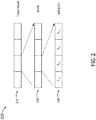
- FIG. 2 is a diagram illustrating a TDMA data stream 200, in accordance with one or more embodiments of this disclosure.
- TDMA allows multiple users to transmit on a single frequency, with each user given one or more portions of time within a longer time period to transmit a signal.
- TDMA time periods are commonly divided into frames 210, with each frame 210 divided into time slots 220.
- Time slots 220 are defined periods in time that a user may transmit a signal using the TDMA architecture.
- the data transmitted from the node 110 within a time slot 220 may include not only the payload data that the user wants to send (e.g., voice data) but also control data that assists in signal synchronization and propagation. This control data is often included in a preamble of the data stream.
- time slots 220 are further divided into subslots 230.
- subslots 230 may be utilized to support relay node utilization within the ad hoc communication network 100.
- Nodes 110 acting as relays may relay the same signal (e.g., data) or signals that have been algorithmically derived from the data received from the first signal 130.
- nodes 110 may retransmit once within the slot (e.g., a subsequent subslot 230).
- nodes 110 may retransmit more than once within the slot.
- nodes 110 may transmit at every opportunity within the time slot 220.
- initiating nodes 120 or other transmitting nodes 110 that determine that they are the sole connection to other nodes 110 may transmit their signal more than once.
- the TDMA structure only contains subslots 230 (e.g., with time slots 220 and/or frames 210 omitted).
- the subslots 230 may start asynchronously or synchronously, depending on the structure and need of the network.
- an initial TDMA frame starts asynchronously on the transmission of a first signal 130 by a primary transmitter.
- the telecommunication network 100 does not have a TDMA structure.
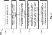
- FIG. 3 is a flow chart illustrating the steps for the method 300 for using subslot 230 in the telecommunication network 100.
- the method 300 includes the step 310 of transmitting a first signal 130 from an initiating node 120 in a first subslot 230.
- An illustration of the first signal 130 being transmitted from an initiating node 120 is shown in FIG. 1 .
- FIG. 2 illustrates the designation of the first subslot 230 as subslot S 1A .
- the method includes the step 320 of receiving the first signal 130 at other nodes 110 in the network in the first subslot.
- the first signal 130 is received by the node 110a in the first subslot S 1a after being sent from the initiating node 120.
- the first signal 130 may also be received by other nodes 110b-c in the first subslot S 1a if they are in range of the initiating node 120.
- the method 300 includes the step 330 of retransmitting the first signal 130 or an algorithmically related first signal 130 in a second subslot 230 subsequent to the first subslot.
- node 110a retransmits the first signal 130 to other nodes 110b-c in the telecommunication network in a subsequent subslot 230 (e.g., subslot S 1b in FIG. 2 ).
- the method 300 further includes the improvement step 340 of preparing a retransmission of at least one of the first signal or the algorithmically related first signal by two or more nodes via a controller, wherein at least two of the first signals or the algorithmically related first signals are time-dispersed.
- Time-dispersion of multiple signals e.g., also referred to as multipath or relay diversity
- time-dispersed signals e.g., two or more signals with slightly different delays
- fading of the signal from each separate transmitter is likely to be uncorrelated resulting in a higher likelihood of the receiver recovering the message when the signals are dispersed in time sufficiently to allow the receiver to resolve the individual paths.
- the first signal 130 or an algorithmically related first signal may be retransmitted by multiple nodes simultaneously multiple times. With every time a node then hears a transmission and/or retransmission, the node has a better chance of correctly receiving the transmission.
- the step 340 of preparing a time-dispersed transmission or retransmission of at least one of the first signal 130 or a time-dispersed algorithmically related first signal by two or more nodes via a controller may occur at any point within the method 300. Step 340 may occur before the transmission of the first signal 130 or the algorithmically related first signal. In the case of coordinated NACKs, a controlling element prepares a coordinated transmission of replica signals by all nodes transmitting in that slot. As another example, the step 340 may occur after the reception of a first signal 130 from an initiating node 120 to a receiving node 110 and before the retransmission of the first signal 130 or the algorithmically related first signal by the receiving node.
- the retransmission (e.g., time-dispersed) may be prepared in response to a previous reception or receptions, where the controlling elements at individual nodes ensure that signals transmitted by multiple nodes that overlap in time and frequency are all replicas of the same signal.
- the NACK slot there is no transmission to relay, but the NACK is in response to previous reception(s), or lack thereof (e.g., missed data).
- the time-diverse retransmission may be transmitted in response to the signal to be relayed (e.g., as in a TDMA network), or in response to an asynchronous first signal that may or may not eventually organize within an ad hoc network to form a TDMA relay structure.
- the method 300 further includes the step 350 of repeating the receiving and retransmitting of a first signal 130 or an algorithmically related first signal by other nodes in subsequent subslots.
- the step 350 may be repeated a number of times, with each set of repeated steps adding data from the first signal 130 or an algorithmically related first signal to subsequent subslots (e.g., slots S 1c and S 1d in FIG. 2 ).
- Contacting every node 110 in the network ensures that the first signal 130 or an algorithmically related first signal 130 will reach the intended node 110. It should be noted that as the number of relays required to allow a signal to propagate across an entire network increases, the number of subslots required to manage the relaying of signal increases as well.
- the number of subslots utilized in the telecommunication network 100 may need to be adjusted according to the topography and number of the relay nodes 110.
- the method 300 does not require routing tables, simplifying the routing process. Signals that return to nodes 110 that have already transmitted or received the first signal 130 or an algorithmically related first signal 130 will convey to the node 110 information regarding the structure, status or other characteristic about the communication network 100. However, these signals may not be retransmitted.
- one or more nodes 110 of the telecommunication network 100 is further configured to control multipath spreading by varying transmission delay with respect to a time reference (start of a subslot or time of reception of the signal to be relayed for example).
- Diversity relay is a multipath-controlling method for ensuring that a transmitted signal reaches its destination, as the higher number of paths that the signal takes, the greater probability that the signal will be received by the intended node 110.
- Multipath time relay provides greatest benefit when the time dispersion at the node 110 is sufficient to allow the node 110 to resolve separate paths, but not so great as to exceed the multipath delay spread capabilities of the node 110 (e.g., such as when using an equalizer or rake receiver). It is also desirable to create a time diverse path in the event that the physical geometry doesn't provide sufficient delay separation between individual relay transmissions. In some embodiments a time diverse path is accomplished by having nodes stagger or dither their transmission (i.e., control multipath spreading by dithering retransmission delay) with respect to the nominal slot start, either deterministically, or in a pseudo random fashion. In some embodiments, the node 110 may determine multipath spreading by self-assessment. In some embodiments, the node 110 may determine multipath spreading through the reception of control data form another node.
- FIG. 4 is a diagram illustrating a communication system containing nodes 110 that relay the first signal 130 or the algorithmically related first signal 130 in a time-diverse multipath arrangement, in accordance with one or more embodiments of this disclosure.
- a first signal 130 is transmitted from an initiating node 120 to other nodes 110a-c in the telecommunication network 100.
- the receiving nodes 110a-c Upon receiving the first signal 130, the receiving nodes 110a-c retransmits the first signal 130 or the algorithmically related first signal 130 to a node 110d that is an intended destination of the first signal 130.
- one, more than one, or all nodes 110 of the communication network 100 may be targeted to receive the first signal 130 or the algorithmically related first signal.
- One or more retransmissions from the retransmission nodes 110a-c may be time delayed (e.g., T1, T2 or T3 in FIG. 4 ) so that the receiving node 110d receives the first signal 130 or the algorithmically related first signal as a time-diverse spread signal. For example, if nodes 110a-c transmit precisely on the start of the subslot, the signals are received at 110d at the respective time of propagation from each node to 110d following the start of the subslot. If the distance from 110a-c to 110d is the same for all three paths, the signals would be received at exactly the same time. Introducing a variable time delay between 110a-c retransmissions can spread the reception time at 110d out to optimize the time dispersion for reception.
- T1, T2 or T3 in FIG. 4 time delayed
- the decision to control multipath spreading can be taken locally or globally.
- the key limitation is that the delay dither should not result in received multipath that exceeds the design capability of the node 110 or telecommunication network 100.
- a node 110 may determine multipath spreading through self-assessment. All nodes 110a-c have the ability to monitor the delay spread that they are seeing and if any of them detect delay spread approaching their limit, the nodes 110a-c would transmit a signal to reduce spread in a slot 220 or subslot 230 designated for signal-spreading control data. If nothing is heard in that slot 220 or subslot 230 for a period of time, time-delay of the signal may be increased by some modest amount.
- the multipath delay spread would be decreased and maintained at the lower level for a longer period (e.g., hysteresis) before allowing a future increase.
- multipath delay can be managed between neighbors.
- the only transmissions that matter to a node 110 are transmission to and from neighboring nodes 110, and not transmissions to and from nodes 110 not within range.
- each node 110 is able to assess locally what delay spread it is seeing and could report that metric when it transmits (e.g., the node 110 may receive control data from other neighboring nodes 110). If all of a node's neighbors report low delay spread, a node 110 may increase the time delay that it retransmits the signal.
- nodes can explicitly report which nodes that they are hearing (e.g., when they transmit in the first subslot and include a node identifier field, but not in a subsequent subslot) and signal characteristics such as received SNR and delay.
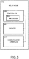
- FIG. 5 is a block diagram illustrating a node 110 used for relaying a first signal 130 or the algorithmically related first signal 130, in accordance with one or more embodiments of this disclosure.
- the nodes 110 are configured to opportunistically receive a first signal 130 from the initiating node 120, and retransmit the first signal 130 or the algorithmically related first signal to another node 110.
- the relay nodes 110 include a controller 500.
- the controller 500 provides processing functionality for the relay node 110 and can include any number of processors 504.
- the one or more processors 504 may include any processors 504 used in the art including, but not limited to, field programmable gate arrays (FPGA), and application-specific integrated circuits (ASIC).
- the controller 500 may utilize the one or more processors 504 to receive and decode incoming transmissions and recode and retransmit the relayed transmissions.
- the controller 500 may also include resident or external memory 508 for storing data, executable code, and other information accessed or generated by the relay node 110.
- the controller 500 can execute one or more software programs embodied in a non-transitory computer readable medium (e.g., a memory 508) that implements techniques described herein.
- a non-transitory computer readable medium e.g., a memory 508
- the controller 500 is not limited by the materials from which it is formed or the processing mechanisms employed therein.
- the memory 508 can be an example of a tangible, computer-readable storage medium that provides storage functionality to store various data and/or program code associated with operation of the relay node 110 and or controller 500, such as software programs and/or code segments, or other data to instruct the controller 500, and possibly other components of the relay node 110.
- the memory 508 can store data, such as a program of instructions for operating the relay node 110 and/or incoming data from the first signal 130 or the algorithmically related first signal 130. It should be noted that while a single memory 508 is described, a wide variety of types and combinations of memory 508 (e.g., tangible, non-transitory memory) can be employed.
- the memory 508 can be integral with the controller 104, can comprise stand-alone memory, or can be a combination of both. Some examples of the memory 508 can include removable and non-removable memory components, such as random-access memory (RAM), read-only memory (ROM), flash memory (e.g., a secure digital (SD) memory card, a mini-SD memory card, and/or a micro-SD memory card), solid-state drive (SSD) memory, magnetic memory, optical memory, universal serial bus (USB) memory devices, hard disk memory, external memory, and so forth.
- RAM random-access memory
- ROM read-only memory
- flash memory e.g., a secure digital (SD) memory card, a mini-SD memory card, and/or a micro-SD memory card
- SSD solid-state drive
- magnetic memory magnetic memory
- optical memory optical memory
- USB universal serial bus
- the relay node 110 includes a communication interface 512.
- the communication interface 512 can be operatively configured to communicate with the components of the relay node 110 and the controller 500.
- the communication interface 512 can be configured to retrieve data from the controller 500 or other devices, transmit data for storage in memory 508, retrieve data from storage in memory, 508 and so forth.
- the communication interface 512 can also be communicatively coupled with the controller 500 to facilitate data transfer between components of the relay node 110 and the controller 500.
- the communication interface 512 is described as a component of the relay node 110, one or more components of the communication interface 512 can be implemented as external components communicatively coupled to the relay node 110 via a wire and/or wireless connection.
- the relay node 110 may also include and/or connect to one or more input/output (I/O) devices.
- the communication interface 512 includes or is coupled to a transmitter, receiver, transceiver, physical connection interface, or any combination thereof.
- the first signal 130 or the algorithmically related first signal 130 of at least one subslot 230 is combined with a replica or algorithmically related first signal or the algorithmically related first signal 130 of at least one other subslot 230.
- nodes 110 receiving the first signal 130 or the algorithmically related first signal 130 can combine information obtained in the two subslots 230 to improve the received first signal or the algorithmically related first signal 130 to the point where it can be successfully decoded.
- Subslots 230 may be combined using soft decisions, which uses metrics for the quality of received bits or symbols to weight the contribution from each copy of the same bit or symbol in the detection process.
- first signals 130 may be captured, retained, and the subslots 230 combined by any of the commonly used diversity receive combining techniques. By combining subsequent slots in this manner, the subsequent impulse response may be assessed and used to determine if artificial delay may be added to increase multipath capabilities (e.g., an enhancement in diversity gain).
- CRC cyclic redundancy check
- the telecommunication network 100 further comprises a feedback protocol.
- Feedback protocols are necessary in networks to resolve or prevent errors in data transmissions.
- the feedback protocol is generated by designating a slot 220 following a data transmission slot 220 as a negative-acknowledgement (NACK) slot 220, as shown in FIG. 6 .
- NACK negative-acknowledgement
- Any nodes 110 that require retransmission transmit the identical retransmission request in the slot 220, which could then be relayed in subslots 230.
- a single node 110 or multiple nodes 110 requiring retransmission will provide the same NACK when multiple nodes send a NACK simultaneously, the result is beneficial rather than destructive because the receiving nodes 110 see the same kind of artificial multipath as in McGibney diversity relay.
- the feedback protocol includes an automatic repeat request (ARQ) protocol.
- ARQ automatic repeat request
- NACK requests are prepared before the coordinated retransmission of first signals or algorithmically related first signals by all nodes 110 transmitting in a slot (i.e., the NACK is not a rebroadcast of the first signal 130).
- Adaptation of global dithering of timing to improve received time dispersion of relayed signals may also be accomplished in a fashion similar to negative acknowledgment based ARQ protocols.
- data slots 220 are designated to allow a receiving node 110 to at least one of object to an increase in dither or request an increase in dither.
- the global dither can therefore be managed by the telecommunication network 100 at the node 110 level with low overhead. It should be noted that dedicated management slots 220 should be far enough apart as to not adversely impact overheads and balanced for adaptability.
- Efficiency in telecommunication networks 100 may be increased through optimization of the number of subslots 230 utilized within a data slot 220 of a frame 210.
- the telecommunication network 100 is further configured to at least one of increase the number of subslots 230 in a slot 220 depending on one or more data signals sent from one or more nodes or decrease the number of subslots 230 in a slot 220 depending on one or more data signals sent from one or more nodes..
- one or more subslots 230 have been designated as subslots one, two and three, and one or more nodes 110 have been designated as nodes A, B, C, D, and E.
- the number of subslots 230 in a slot 220 may be reduced if one or more subslots 230 are not utilized. For instance, if node A transmits in subslot one, nodes B and C relay in subslot two, and nodes D and E relay in subslot three, if there are no nodes beyond D and E, that would mean that three subslots 230 were not required and that the message propagated to all nodes 110 within the network within two subslots 230. If all nodes 110 initiating the transmission are found to only require two subslots 230 to propagate the signal to all nodes 110, then the number of subslots 230 may be reduced. In another example, the number of subslots 230 may be increased.
- the node 110 may object to any reduction in the number of subslots 230.
- the node 110 may request that the number of subslots 230 increase.
- the telecommunication network 100 further comprises a slot 220 dedicated to at least one of vetoing a change in subslot 230 number or request an increase in subslot 230 number.
- a mechanism for vetoing may be a dedicated slot 220 in which all nodes 110 that wish to maintain the current number of relay opportunities based on the number of subslots 230 transmit an agreed upon message.
- a second dedicated slot 220 may be assigned to allow any node 110 requiring more subslots 230 for relaying to transmit an agreed upon message to increase the number of subslots 230.
- FIG. 7 is a diagram illustrating a series 700 of slots (e.g., slots 710-750) with possible arrangements of subslots 230, in accordance with one or more embodiments of this disclosure.
- a slot 710-750 begins with a primary subslot 230, designated by a 'P' (e.g., hatched background).
- Subslots 230 used in a relay context are shown with an 'R' with a subscript indicating which relay level they represent.
- Aligned primary slots 220 across rows permit adaptation within the slots/subslots between the aligned primary slots to occur with some degree of robustness possible because the aligned primary slots can be consistent across all possible subslot 230 arrangements.
- an adaptation within the slot structure could include slots with zero, one, two, three, or five relay subslots (e.g., in slots 710-750).
- the adaptation rules are modified for a three to five, or five to three, transition as the adaptation is a transformation by two subslots 230, rather than a change by one subslot 230. If less than the maximum number of relay subslots 230 are being used, then an opportunity exists for signals other than the first signal 130 or the algorithmically related first signal 130 to be transmitted.
- the ability to support other services can be added as the capacity improves (e.g., when the number of relay nodes needed is reduced).
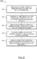
- FIG. 8 is a flow diagram illustrating a method 800 for managing power within the telecommunication network 100, in accordance with one or more embodiments of this disclosure.
- the method 800 includes the step 810 of requiring each node to report a unique identification when they are the initiating node. Node 110 usage data may then be used for local power optimization of the telecommunication network 100. In some embodiments, the method 800 includes the step 820 of requiring all nodes 110 report who they hear primary transmissions of the first signal 130 or the algorithmically related first signal from with an indication of margin. Primary transmission denotes the first time that a node 110 has received the first signal 130 or the algorithmically related first signal. Node 110 reception data may then also be used in local power optimization.
- the method 800 further includes the step 830 of reducing the power of a node 110 if all neighboring nodes 110 report a sufficient link margin to allow a reduction in power. For example, the power of a transmitting node 110 may be reduced if a neighboring node 110 determines that the transmitting node 110 could reasonably operate at half transmission power.
- the method 800 further includes the step 840 of evaluating connectivity and/or topology variability through adjusted data rates or power. For example, using a higher data rate may decrease the transmission time of a transmitting node 110, which may decrease power consumption.
- using a lower data rate may allow a longer transmission distance, reducing the number of subslot 230 used to relay the signal, thereby reducing the overhead and increasing the data capacity of the telecommunication network 100.
- the use of more efficient data transmission waveform may reduce power consumption.
- a binary phase shift keying (BPSK) signal may be converted to a quadrature phase shift keying (QPSK) signal, resulting in a doubling of the data rate for the signal and increased power efficiency.
- the data rate is set by the node sending the first signal 130 or the algorithmically related first signal.
- the data rate may be changed by nodes acting as relays along the signal path. However, changes in the data rate must be coordinated with other nodes within the communication network 100 to ensure that all overlapping transmissions are replicas.
- the method 800 further includes the step 845 of managing global power adaptation through dedicated management slots 220 or reducing power at specific times if no node 110 objects. For example, if any node 110 sends the defined agreed upon signal (e.g., or packet) requesting increased power in a management slot 220 designated for power management, then the entire telecommunication network 100 would increase power.
- the defined agreed upon signal e.g., or packet
- data rates and/or power management within a communication network 100 may be modified (e.g., optimized) according to changes in network topography.
- a lower data rate would be considered if the signal strength dropped because the distance between nodes increased or the power of the nodes had been reduced.
- an overall reduction in the area covered by the communication network 100 e.g., a communication network 100 that has reduced from covering 10000 square kilometers to 1000 square kilometers, comprising one or more mobile nodes 110
- the method 300 further includes the step of operating a coding scheme.
- all nodes 110 acting as a relay need to send a signal that encodes exactly the same message sent from the initiating node 120.
- the signals transmitted by the initiating node and relay node for the same message may differ due to coding schemes (e.g., error correction codes such as convolutional codes), which are then algorithmically derived back into the same message.
- coding schemes e.g., error correction codes such as convolutional codes
- Subslots used to relay data do not necessarily have to be a direct copy of the first signal 130 or the algorithmically related first signal in all cases. All relays need to send exactly the same signal in response to a received signal, but that does not need to be identical to the received first signal, the constraint is only that signals that overlap at a receiver on a frequency in time must be replicas of one another so that they can be combined. That replica signal can be derived algorithmically from the first signal 130. For example, nodes 110 can compute parity bits from the first signal 130 and send those.
- the method for generating the parity bits changes from subslot to subslot but is predefined so all relays do the same thing for every subslot, nodes that are not able to detect a message from a single subslot can improve their likelihood of detecting a message using multiple received subslots, each of which carries different parity bits.
- the method is general, but specific examples can be given: Reed Solomon codes could be used in one instance, convolutional codes in another, Turbo-codes or LDPC codes in still others.
- the first signal 130 or algorithmically related first signal includes a forward error correction code with a rate equal to or less than 1.
- Convolutional codes are a type of error-correcting codes that generate parity symbols through a sliding application of a Boolean polynomial function to a data stream, which can then be decoded using the Viterbi algorithm.
- Convolutional codes are of particular use with fading channels, as they can be used to determine probabilities correctness of bits for signals within transmissions where errors are present (e.g., through soft decision decoding).
- Convolutional codes may be systematic, where the encoded message includes the original data bits, potentially interleaved or permuted, as well as parity bits derived from the original data bits.
- Non-systematic codes do not send the original data bits, but only bits derived from the polynomial functions.
- non-systematic codes are preferable when convolutional codes are employed with a traditional Viterbi maximum likelihood decoder.
- convolutional codes are used to form a code that is decoded by with a turbo-code approach, systematic convolutional codes are preferred. In either case, so long as the code rate is 1 or less, the original message can be recovered if there are no errors in the transmission. Lowering the rate of the code improves the ability to recover the original message in the presence of errors.
- the coding scheme may include the step of recovering the data in the first signal 130 or algorithmically related first signal and validating the integrity of the data.
- a non-systematic convolutional code could use a rate 1/3 convolutional code, using 3 polynomials to generate the encoded message. If the output of the first polynomial were sent as the primary message, with a CRC appended, the original message could be recovered if there were no errors in the reception. In the first subsequent subslot, all transmissions could use the output of the second polynomial, again with a CRC appended.
- Retransmissions by nodes that received the primary message would be made by detecting the first signal 130 or the algorithmically related first signal, confirming from the CRC that it was not corrupted, recovering the original message bits, encoding them with the rate 1/3 encoder and using the bits from the second polynomial as the basis of the re-transmission. Similarly, for the second subsequent subslot, the message would be based on the bits encoded by the third polynomial.
- a receiver can attempt to decode the message with any individual slot as a rate 1/3 code, punctured to rate 1. If it receives any two subslots, it can attempt the decoding as a rate 1/3 code punctured to rate 1/2.
- the decoding can use the full power of the rate 1/3 code.
- An obvious extension to this includes sending encoded messages which have some amount of redundancy to allow for error correction, for example, by basing the messages on a rate 1 ⁇ 4 convolutional code, with the primary message consisting of the output of the first polynomial and the first 1/3 of the bits output from the fourth polynomial.
- the second subslot would use the encoded bits from the second polynomial and the second 1/3 of the bits from the fourth polynomial and the third sub-slot would use the output of the third polynomial and the last 1/3 of the bits from the fourth polynomial.
- the coding scheme may include evaluating the data from at least one of the algorithmically related first signal or a combination of the first signal 130 and the algorithmically related first signal.
- the evaluation of the first signal 130 and the algorithmically related first signal may be performed through the use of turbo codes.
- Turbo codes are a type of convolutional code that combines two convolutional codes to achieve better performance than a convolutional code by itself. Signals are run through two or more encoding steps, transmitted, and the signals are decoded at the receiving node. The process of turbo coding can be expanded to an additional splitting step and combining step, resulting in an increased code rate without having to change on-air bandwidth or modulation.
- the retransmission of the first signal 130 or algorithmically related first signal in the subsequent subslot is further prepared to contain parity bits derived from the data of the first signal 130 or algorithmically related first signal.
- the data from the first signal 130 or the algorithmically-derived first signal may be encoded into data bits and parity bits.
- the convolutional codes used in the coding scheme are systematic convolutional codes, or are codes where the original message bits can be recovered by reordering the sequence of the bits.
- the coding scheme and the convolutional codes used in the coding scheme are associated within STANAG 4538 data link protocols or other code combining automatic repeat request (ARQ) protocols.
- the coding scheme may include combining the convolutional codes into a turbo code.
- the turbo code may be encoded by sending the data through a convolutional encoder, then sending an interleaved copy of the data through the same convolutional encoder. The original data, checksum 1, and checksum 2 are combined into one data stream.
- the encoded sequence will be X 1 Y 1 Z 1 X 2 Y 2 Z 2 X 3 Y 3 Z 3 ...
- X n Y n Z n where X 1 ...X n are the data bits, Y 1 ...Y n are the checksum bits, and Z 1 ...Z n are the checksum bits from an interleaved convolutional encoder.
- the coding scheme may include splitting the turbo code into two or more data streams, wherein a first data stream comprises checksum bits from the first convolutional encoder and data bits, and a second data stream comprises checksum bits from the interleaved convolutional encoder and interleaved data bits.
- a first data stream comprises checksum bits from the first convolutional encoder and data bits
- a second data stream comprises checksum bits from the interleaved convolutional encoder and interleaved data bits.
- X n Y n Z n may be further split into two signals: X 1 Y 1 X 2 Y 2 X 3 Y 3 ...X n Y n and I 1 Z 1 I 2 Z 2 I 3 Z 3 ...I n Z n , where X 1 ...X n are the data bits, Y 1 ...Y n are the checksum bits from the convolutional encoder, Z 1 ...Z n are the checksum bits from the interleaved convolutional encoder, and I 1 ...I n are the interleaved data bits.
- the coding scheme may include preparing and retransmitting the algorithmically related first signal in a subsequent subslot.
- the data streams may be transmitted independently from each other.
- the data stream containing checksum bits from the convolutional encoder may be transmitted in a first subslot, wherein the data stream containing checksum bits from the first interleaved convolutional encoder may be transmitted in a second subsequent subslot.
- the independent data streams may also be sent within different subslots within the same time slot.
- the coding scheme may include receiving the transmitted data stream (e.g., by a receiver on a node 110).
- the coding scheme may include at least one of combining the data streams into a turbo code and decoding the data stream with a turbo code decoder, or decoding one or more data streams with a Viterbi decoder.
- a node 110 may receive the two data streams from the transmitted split signal, each from separate slots, and combine them.
- the interleaver may be different on both slots 220, as the reception of any two slots 220 may be decoded with a turbo code decoder.
- When transmitted in subsequent slots 220 with a high enough SNR either reception can be received independently. For example, if both transmissions were received, but both receptions have errors, the data can be combined and decoded with a turbo code decoder.
- a Viterbi decoder may be used to decode the received signals, particularly if at high SNR values (i.e., the coded signals may be decoded through different iterations of decoders until one decoder is found with the fewest errors or zero errors.
- three or more convolutional codes e.g., a "super turbo code” may be utilized to encode and decode first signals or algorithmically related first signals.
- the first signal 130 or algorithmically related first signal is further prepared to contains parity bits derived from the data of the first signal 130 or algorithmically related that are different from the parity bits of one or more preceding retransmissions.
- the data from one or more combinations of a first signal 130 and subsequent algorithmically related signals are evaluated, and a retransmission of the first signal 130 or algorithmically related first signal if prepared based on the evaluation.
- the combination of the received first signal or algorithmically related first signal can at least one of increase the number of decoding algorithms that can recover the data or decrease the code rate.
- the coding scheme may be identical for any retransmission. In some embodiments, the coding scheme may be different for any retransmission.
- the decoding scheme can decode any retransmission independently. In some embodiments, the decoding scheme can be improved by the reception of multiple retransmissions. In some embodiments, multiple decoding schemes can be used to decode a single transmission. In some embodiments, multiple decoding schemes can be used to decode receptions improved by the reception of multiple retransmissions. It should be known that one slot, multiple slots, or a combination of slots may be used in association with the coding scheme. For example, multiple subslots may be used for redundant messaging (e.g., in case that an initial signal is missed).
- the method 850 allows the encoding of a first signal 130 into two coded signals with differing coding properties, and allows the reception of either of the two coded signals to be received in order to recover data from the first signal 130 with a Viterbi decoder, or reception of both signals (with errors) to be decoded by a Turbocode decoder.
- the coding scheme further includes a code puncturing scheme, wherein data streams within two or more subslots coding redundant first signals are punctured with a unique puncture pattern.
- Data puncturing is the process of removing some parity bits from an encoded signal after encoding with an error-correction code, and is commonly associated with convolutional or turbo codes. Puncturing reduces the number of transmitted bits, which increased the overall data transmission rate. For example, the turbo convoluted code X 1 Y 1 X 2 Y 2 X 3 Y 3 ...
- punctured turbo code e.g., or other punctured, convolutionally encoded code
- the payload data is still intact once the transmission is decoded.
- first signals or algorithmically related first signals in multipath or subslot-repeated transmissions may be punctured multiple times and expanded. This puncture rate expansion works with both systematic and non-systematic convolutional codes as long as the transmitted data is the same underlying sequence that has been punctured differently.
- FIG. 9 is a diagram illustrating a setup 900 for puncture rate expansion within a slot, in accordance with one or more embodiments of this disclosure.
- the convoluted data X A1 Y A1 X B1 Y B1 X C1 Y C1 is punctured using the puncture pattern 111010.
- the CRC passes, then the reception was satisfactory and the data can be retransmitted. If the CRC fails, the data is not satisfactory and the soft decisions are stored for the next slot.
- the data after the first reception is expanded after the first reception to produce X A1 Y A1 X B1 0 X C1 0....
- the data is reencoded and punctured with a second distinct pattern, 101110, a pattern capable of converting a signal of X A2 Y A2 X B2 Y B2 X C2 Y C2 ... to X A2 0 XB 2 Y B2 X C2 0 ... that may be transmitted.
- the soft decisions are combined in such a way that there are fewer expanded bits, using the first and second combined equation 925.
- the data is reencoded and punctured with a third distinct pattern, 101011, a pattern capable of converting a signal of X A3 Y A3 X B3 Y B1 X C3 Y C3 ... to X A3 0 X B3 0 X C3 Y C3 ... that is transmitted.
- the soft decisions are combined in such a way that all checksum bits have been transmitted at least once, using the first, second, and third combined equation 935.
- the code puncturing scheme is adjusted to optimize the number of times that the bits are punctured. For example, it may be more suitable to puncture a non-systematic convolutional code with retransmissions set up to minimize the number of times the same unique bit is analyzed, and maximizing the number of different bits that are analyzed. For instance, if two of six bits are punctured using a non-systematic convolutional code, each bit will be analyzed twice after three transmissions, whereas a systematic convolutional code may analyze some bits three times, and other bits only once.
- Both the expanded use of turbo codes and puncture rates may modify the code rate without having to change the on-air bandwidth or modulation, which allows either a longer range, or a lower transmit power for the same probability of correct reception.
- Lower transmit power will increase the battery life of power constrained nodes (e.g., battery powered radios) and reduce the range in which adversaries can detect radio transmitters.
- Each expansion method has its own advantage and disadvantage. Puncture rate expansion has a lower complexity receiver and can be used with higher data rates or with less processing power. Puncturing also reduces redundancy, which increases the code rate i.e., from rate 1 ⁇ 2 to rate 3 ⁇ 4) making the transmission less robust.
- Turbo code expansion has a more complex receiver but can operate with poorer signal quality.
- the management data of the telecommunication network 100 is all overhead data as far as the user is concerned and ideally would be transmitted in a way that doesn't impact the user (e.g., through transmitting in a different frequency).
- nodes 110 When two nodes 110 that are in range of each other transmit on the same frequency, their transmissions interfere with each other. If the nodes 110 are transmitting identical data, the interference can be constructive and improve the reception at a receiver node 110. If the data is different the interference is destructive and can prevent reception of either transmission at the receiving node 110.
- FIG. 10A is a diagram illustrating two transmitting nodes 110 operating in a telecommunication network 100 with on-air collisions.
- the transmitting nodes are only two hops away from each other. Signals transmitted by transmitting nodes one and three collide at node two, whereas node four only receives one signal from node three. With only two nodes 110 acting as a relay node, transmitting nodes can never be far enough apart that there will not be on air collisions.
- FIG. 10B is a diagram illustrating two transmitting nodes 110 operating in a telecommunication network 100 without on-air collisions (e.g., the transmitters are three hops apart.
- a potential for interference in transmitting with relay nodes 110 arises from signals retransmitted from relay nodes 110 interfering with new signals sent from initiating nodes 120. For example, after sending a first signal 130 to a relay node 110, in the first subslot 230, an initiating node 120 may then transmit overhead data (e.g., a second signal) to other nodes 110 in a subsequent subslot 230. If the node 110 receiving the initial signal retransmits the first signal 130 or algorithmically related first signal in the second subslot 230, the first signal 130 and the overhead data will interfere with each other. In this scenario, additional frequencies may be utilized.
- overhead data e.g., a second signal
- the initiating node 120 is further configured to transmit a second signal in the second subslot 230 (e.g., subsequent subslot) or a third subslot 230 subsequent to the third subslot in a different frequency than the retransmitted first signal or algorithmically related first signal 130.
- one or more nodes 110 of the communication network 100 may comprise half duplex devices that communicate with other half-duplex devices, but not simultaneously. For example, for these half-duplex devices, the relay will receive in the first subslot 230, transmit in the second subslot 230 and will not be able to receive another signal until the third subslot.
- FIG. 11A-C is a diagram illustrating a method for relaying transmissions without collisions in a three-relay telecommunication network 100.
- a first signal 130 from node one is initially transmitted to node two in subslot one (e.g., FIG. 11A ).
- Node two then transmits the first signal 130 to node three in subslot two (e.g., FIG. 11B ).
- Node one also receives a retransmitted first signal or algorithmically related first signal 130 from node two, but disregards it with respect to retransmitting the first signal 130 or algorithmically related first signal.
- node one may also take note of other aspects of the received transmission (e.g., whether no other retransmission is heard, or whether the retransmission is transmitted on the same frequency, either in the next subslot or in a later first subslot).
- both node one and node two will switch to a secondary frequency.
- node three is shown transmitting the first signal 130 or algorithmically related first signal to nodes two and four, while node one is transmitting overhead data to node two using the secondary frequency (e.g., in a second subslot 230 subsequent to the first subslot 230).
- the two signals reaching node two do not interfere with each other, as the frequencies of the two transmissions are different.
- FIG. 12A-C are diagrams illustrating the use of frequency diversity in an eight-node mesh TDMA network using a first, a second, and a third subslot, respectively. Transmissions with similar frequencies are shown with identical arrow patterns in FIGS. 12A-C .
- At least one node 110 that is not within the range of the initiating node 120 is configured to transmit a second signal or algorithmically related second signal in at a first subslot 230 and/or a second subslot 230 subsequent to the first subslot 230 in a different frequency than initiating node one.
- node three in FIG. 12A is configured to transmit a second signal or algorithmically related second signal in at a first subslot 230 and/or a second subslot 230 subsequent to the first subslot 230 in a different frequency than initiating node one. For example, node three in FIG.
- the initiating node 120 e.g., node one
- nodes two and six will not receive the second signal or algorithmically related second signal if they are only capable of receiving on a single channel and are configured to listen for the signal from node one in this subslot.
- the second signal or algorithmically related second signal may contain data similar or dissimilar to the first signal 130 or algorithmically related first signal.
- nodes within the communication network 100 may act as relays when they are capable of doing so. By having all nodes 110 always acting as relay nodes when possible, no overhead is needed to assign specific nodes for relaying, reducing resource needs required to operate the communication network 100.
- one of the nodes 110 that received the first signal 130 from node one retransmits the first signal 130 or algorithmically related first signal 130 in the second subslot to nodes 110 in range using the same frequency as the initial transmission of the first signal 130 from node one to node two.
- the node that initially transmitted the first signal 130, node one is transmitting another signal (e.g., a secondary signal) to the second subslot 230 using a secondary frequency
- another signal e.g., a secondary signal
- a node not in range of node two, node four is transmitting a third signal within the second subslot 230 using a secondary frequency.
- Nodes five and six receive both signals from nodes one and two if they are capable of receiving signals on multiple frequencies. If nodes five and six are only capable of receiving a single frequency, then they will only receive transmissions from node one or node two.
- Node two acting as a transceiver, would not be able to receive the transmission from node one at the same time that it is transmitting to nodes one, three, five, six and seven. It should be noted that some transmissions in FIG. 12B (e.g., from nodes five and six) were removed for clarity. All nodes that receive a transmission would then automatically retransmit the signal. It should also be noted that the nodes 110 in FIG. 12B have full duplex capability, and can transmit on a different frequency than the frequency for which they are receiving transmissions. Communication networks 100 operating with one or more nodes 110 with half duplex capability may have different relay capabilities or patterns, as half duplex nodes are not capable of transmitting on different frequencies that the frequency for which they are receiving transmissions. For example, a node sending a first signal 130 may wait until after its neighbors have had an opportunity to retransmit the first signal 130 or algorithmically related first signal before sending a second signal in a subsequent subslot on the same or different frequency.
- one of the nodes 110 that received the first signal 130 or algorithmically related first signal from node two retransmits the first signal 130 or algorithmically related first signal using a third subslot 230 to all neighboring nodes.
- nodes 110 When this transmission occurs, all nodes within the network have received the first signal 130 or algorithmically related first signal at which time the first signal 130 or algorithmically related first signal will no longer propagate.
- other nodes 110 have transmitted, and may continue to transmit, signals through the telecommunication network 100.
- nodes 110 As in FIG. 12B , some transmissions in FIG. 12C were removed for clarity (e.g., all nodes that receive a transmission automatically retransmit the signal).
- the method of routing signals in a telecommunication network 100 further includes adjusting the power level of a node based upon at least one characteristic of the reception of the first signal 130 or algorithmically related first signal, or the condition of the neighboring nodes 110.
- overhead data could be transmitted globally at a high power and a low data rate, which will allow the node to transmit at maximum range.
- the data waveforms may then adjust the power rate and/or the data rate according to one or more qualities of the link. For instance, the data rate which can impact the topology of the network, and the number of subslots, which affects the overhead, may be jointly optimized to maximize the capacity of the network. Power levels may also be adapted on a node-by-node basis.
- a node acting only as a relay may be turned off if it is determined that another node may provide the same action (i.e., a reduction of redundant nodes).
- data may also be modulated to increase data rates. For example, switching from a QPSK modulation to an eight-phase shift keying (8PSK) modulation could increase data rate with a compensatory decrease in power usage.
- PSK eight-phase shift keying
- By adjusting power locally or globally within the telecommunication network 100 data may be efficiently managed without overextending the data capacity of the telecommunication network 100.
- Other characteristics of the first signal 130, algorithmically related first signal, or condition of the neighboring nodes may be used as a basis for adjusting the power level of a node. Therefore, the above description should not be interpreted as a limitation of the present disclosure, but merely an illustration.
- the methods described herein for modifying, delaying, otherwise adapting signals received and/or transmitted by the nodes may be performed by the components operating within the node including but not limited to the controller 500, memory 508, processors 504, or the communication interface 512.
- embodiments of the methods disclosed herein may include one or more of the steps described herein. Further, such steps may be carried out in any desired order and two or more of the steps may be carried out simultaneously with one another. Two or more of the steps disclosed herein may be combined in a single step, and in some embodiments, one or more of the steps may be carried out as two or more substeps. Further, other steps or substeps may be carried in addition to, or as substitutes to one or more of the steps disclosed herein.
Landscapes
- Engineering & Computer Science (AREA)
- Computer Networks & Wireless Communication (AREA)
- Signal Processing (AREA)
- Quality & Reliability (AREA)
- Mobile Radio Communication Systems (AREA)
Applications Claiming Priority (1)
| Application Number | Priority Date | Filing Date | Title |
|---|---|---|---|
| US16/810,542 US11464009B2 (en) | 2020-03-05 | 2020-03-05 | Relays in structured ad hoc networks |
Publications (2)
| Publication Number | Publication Date |
|---|---|
| EP3876455A1 true EP3876455A1 (de) | 2021-09-08 |
| EP3876455B1 EP3876455B1 (de) | 2023-07-26 |
Family
ID=74859346
Family Applications (1)
| Application Number | Title | Priority Date | Filing Date |
|---|---|---|---|
| EP21161039.9A Active EP3876455B1 (de) | 2020-03-05 | 2021-03-05 | Relais in strukturierten ad-hoc-netzwerken |
Country Status (2)
| Country | Link |
|---|---|
| US (1) | US11464009B2 (de) |
| EP (1) | EP3876455B1 (de) |
Cited By (1)
| Publication number | Priority date | Publication date | Assignee | Title |
|---|---|---|---|---|
| EP4297316A1 (de) * | 2022-06-20 | 2023-12-27 | Rockwell Collins, Inc. | Verbesserung einer kontinuierlichen übertragung mit kooperativer übertragung |
Citations (5)
| Publication number | Priority date | Publication date | Assignee | Title |
|---|---|---|---|---|
| US4639937A (en) | 1983-12-07 | 1987-01-27 | Harris Corporation | HF avalanche relay communication technique |
| US6594273B1 (en) | 1999-07-09 | 2003-07-15 | Telecommunications Research Laboratories | Self-configuring radio network |
| US7103371B1 (en) * | 2003-10-22 | 2006-09-05 | Itt Manufacturing Enterprises, Inc. | Method and apparatus for dynamic voice reservation within wireless networks |
| US20130301633A1 (en) * | 2007-08-02 | 2013-11-14 | Trellisware Technologies, Inc. | Method and system for synchronization of time-slotted barrage relay networks |
| US20150163720A1 (en) * | 2012-11-06 | 2015-06-11 | Universidade Do Porto | Density-aware zone-based packet forwarding in vehicular networks |
Family Cites Families (29)
| Publication number | Priority date | Publication date | Assignee | Title |
|---|---|---|---|---|
| ATE84656T1 (de) | 1986-04-09 | 1993-01-15 | Siemens Ag | Verfahren zur uebertragung digitaler signale bei mobilfunksystemen. |
| FR2608874B1 (fr) | 1986-12-19 | 1989-03-24 | Trt Telecom Radio Electr | Procede de reglage du retard entre stations dans un systeme de transmission d'informations comprenant un grand nombre de stations relais en cascade et utilisant dans un sens de transmission le principe dit d'a.m.r.t. et systeme pour lequel est mis en oeuvre un tel procede |
| US4887050A (en) | 1989-03-31 | 1989-12-12 | Motorola, Inc. | Frequency control apparatus and method for a digital radio receiver |
| US5222101A (en) | 1991-05-03 | 1993-06-22 | Bell Communications Research | Phase equalizer for TDMA portable radio systems |
| US5155742A (en) | 1991-05-03 | 1992-10-13 | Bell Communications Research, Inc. | Time dispersion equalizer receiver with a time-reversal structure for TDMA portable radio systems |
| SE9400722L (sv) | 1994-03-03 | 1995-09-04 | Telia Ab | Anordning för att förbättra funktion i radiokommunikationssystem |
| IL117221A0 (en) | 1995-02-28 | 1996-06-18 | Gen Instrument Corp | Configurable hybrid medium access control for cable metropolitan area networks |
| US5790598A (en) | 1996-03-01 | 1998-08-04 | Her Majesty The Queen In Right Of Canada | Block decision feedback equalizer |
| US6023477A (en) | 1996-12-18 | 2000-02-08 | Ericsson Inc. | System and method of time and frequency synchronization in a radiocommunication system |
| US7536624B2 (en) | 2002-01-03 | 2009-05-19 | The Directv Group, Inc. | Sets of rate-compatible universal turbo codes nearly optimized over various rates and interleaver sizes |
| IL126540A0 (en) | 1998-10-11 | 1999-08-17 | Tadiran Spectralink Ltd | Digital data bi-directional communication method and apparatus |
| US6659947B1 (en) | 2000-07-13 | 2003-12-09 | Ge Medical Systems Information Technologies, Inc. | Wireless LAN architecture for integrated time-critical and non-time-critical services within medical facilities |
| US7023824B2 (en) | 2001-02-27 | 2006-04-04 | Telefonaktiebolaget L M Ericsson (Publ) | Method, apparatus, and system for optimizing transmission power and bit rate in multi-transmission scheme communication systems |
| WO2003003672A2 (en) * | 2001-06-28 | 2003-01-09 | King's College London | Electronic data communication system |
| JP4558739B2 (ja) | 2003-10-28 | 2010-10-06 | 株式会社エヌ・ティ・ティ・ドコモ | マルチキャストサービスを提供する方法 |
| KR100656385B1 (ko) | 2005-12-21 | 2006-12-11 | 전자부품연구원 | 선형 구조를 가지는 실시간 무선 센서 네트워크 통신방법 |
| US20070195746A1 (en) | 2006-02-23 | 2007-08-23 | San Diego Research Center, Inc. | Topology Management, Power Control and Cross-Layer Design for Wireless Mobile Ad Hoc Networks with Directional Antennas |
| US7924761B1 (en) * | 2006-09-28 | 2011-04-12 | Rockwell Collins, Inc. | Method and apparatus for multihop network FEC encoding |
| US7865813B2 (en) | 2007-07-30 | 2011-01-04 | Marvell International Ltd. | Rate matching for a wireless communications systems |
| WO2010041555A1 (ja) | 2008-10-06 | 2010-04-15 | 三菱電機株式会社 | データ中継システムおよび動作時刻割り当て方法 |
| US20110038356A1 (en) * | 2009-08-13 | 2011-02-17 | Yuval Bachrach | VBR interference mitigation in an mmwave network |
| US9185629B2 (en) | 2009-10-15 | 2015-11-10 | Hewlett-Packard Development Company, L.P. | Multi-hop network having reduced power consumption |
| US8885631B2 (en) | 2010-04-26 | 2014-11-11 | Collison Communications, Inc. | Multiuser detection enabled medium access control in mobile ad hoc networks |
| US8559464B2 (en) | 2010-04-30 | 2013-10-15 | International Business Machines Corporation | Synchronizing nodes of a multi-hop network |
| US10542435B2 (en) | 2013-09-24 | 2020-01-21 | Qualcomm Incorporated | Carrier sense adaptive transmission (CSAT) in unlicensed spectrum |
| US10671923B2 (en) | 2013-12-20 | 2020-06-02 | Gemtrex Inc. | Genetic method for the tracking of time varying signals |
| DK3202225T3 (da) | 2014-09-29 | 2019-10-28 | Cardo Systems Ltd | Ad hoc-kommunikationsnetværk og kommunikationsfremgangsmåde |
| CA2972900C (en) | 2014-12-31 | 2023-05-23 | Echostar Technologies Llc | Communications signal isolation on multi-port device |
| FR3037462B1 (fr) * | 2015-06-12 | 2017-07-21 | Thales Sa | Procede de correction locale du chemin de routage dans un reseau ad hoc et reseau ad hoc associe |
-
2020
- 2020-03-05 US US16/810,542 patent/US11464009B2/en active Active
-
2021
- 2021-03-05 EP EP21161039.9A patent/EP3876455B1/de active Active
Patent Citations (5)
| Publication number | Priority date | Publication date | Assignee | Title |
|---|---|---|---|---|
| US4639937A (en) | 1983-12-07 | 1987-01-27 | Harris Corporation | HF avalanche relay communication technique |
| US6594273B1 (en) | 1999-07-09 | 2003-07-15 | Telecommunications Research Laboratories | Self-configuring radio network |
| US7103371B1 (en) * | 2003-10-22 | 2006-09-05 | Itt Manufacturing Enterprises, Inc. | Method and apparatus for dynamic voice reservation within wireless networks |
| US20130301633A1 (en) * | 2007-08-02 | 2013-11-14 | Trellisware Technologies, Inc. | Method and system for synchronization of time-slotted barrage relay networks |
| US20150163720A1 (en) * | 2012-11-06 | 2015-06-11 | Universidade Do Porto | Density-aware zone-based packet forwarding in vehicular networks |
Cited By (1)
| Publication number | Priority date | Publication date | Assignee | Title |
|---|---|---|---|---|
| EP4297316A1 (de) * | 2022-06-20 | 2023-12-27 | Rockwell Collins, Inc. | Verbesserung einer kontinuierlichen übertragung mit kooperativer übertragung |
Also Published As
| Publication number | Publication date |
|---|---|
| US11464009B2 (en) | 2022-10-04 |
| US20210282135A1 (en) | 2021-09-09 |
| EP3876455B1 (de) | 2023-07-26 |
Similar Documents
| Publication | Publication Date | Title |
|---|---|---|
| EP2218204B1 (de) | Verfahren und system zur datenübertragung in einem datennetzwerk | |
| JP4834081B2 (ja) | 複数キャリアのスケジューリング | |
| US8819529B2 (en) | Method of communication | |
| CN102037671A (zh) | Wcdma和lte网络中harq的重传设置的选择 | |
| US20140010147A1 (en) | Data retransmission method, relay station, base station, and communication system | |
| US20220021483A1 (en) | Methods and appratuses for broadcast multicast or groupcast transmission using vertical check blocks | |
| CN108521316B (zh) | 一种混合自动重传请求方法及装置 | |
| CN115298991A (zh) | 使用交叉分组校验块进行网络编码的方法和系统 | |
| CN109565371B (zh) | 针对marc/mamrc系统利用全双工中继器和有限反馈对数字信号的动态和选择性fd-dsdf传输 | |
| EP3876455B1 (de) | Relais in strukturierten ad-hoc-netzwerken | |
| Durvy et al. | Towards reliable broadcasting using ACKs | |
| RU2378770C2 (ru) | Способ и устройство для кодирования и планирования в системах передачи пакетных данных | |
| Ostovari et al. | Reliable broadcast with joint forward error correction and erasure codes in wireless communication networks | |
| Lin et al. | An adaptive hybrid ARQ scheme with constant packet lengths | |
| JP5032678B2 (ja) | 複数キャリアのスケジューリング | |
| Pu et al. | Performance analysis of joint Chase combining and network coding in wireless broadcast retransmission | |
| WO2023050102A1 (en) | Methods and appratuses for wireless communication retransmission using check blocks generated according to subblock interleavers | |
| Swamy et al. | Network coding for real-time wireless communication for automation | |
| Borkotoky et al. | Preliminary results on the performance of an adaptive protocol for packet relay with fountain coding | |
| Anghel et al. | On the performance of selection cooperation ARQ | |
| WO2024065490A1 (en) | Methods, system, and apparatus for joint error correction coding of a self-decodable payload | |
| EP4297316A1 (de) | Verbesserung einer kontinuierlichen übertragung mit kooperativer übertragung | |
| WO2023137720A1 (en) | Methods and apparatuses for network coding-based harq retransmission with scrambling | |
| Park et al. | The performance analysis of hybrid ARQ-II for cooperative communication over wireless channels | |
| Kundu et al. | Implementation and throughput analysis of aggressive packet combining scheme in Rayleigh fading channel |
Legal Events
| Date | Code | Title | Description |
|---|---|---|---|
| PUAI | Public reference made under article 153(3) epc to a published international application that has entered the european phase |
Free format text: ORIGINAL CODE: 0009012 |
|
| STAA | Information on the status of an ep patent application or granted ep patent |
Free format text: STATUS: THE APPLICATION HAS BEEN PUBLISHED |
|
| AK | Designated contracting states |
Kind code of ref document: A1 Designated state(s): AL AT BE BG CH CY CZ DE DK EE ES FI FR GB GR HR HU IE IS IT LI LT LU LV MC MK MT NL NO PL PT RO RS SE SI SK SM TR |
|
| STAA | Information on the status of an ep patent application or granted ep patent |
Free format text: STATUS: REQUEST FOR EXAMINATION WAS MADE |
|
| 17P | Request for examination filed |
Effective date: 20220308 |
|
| RBV | Designated contracting states (corrected) |
Designated state(s): AL AT BE BG CH CY CZ DE DK EE ES FI FR GB GR HR HU IE IS IT LI LT LU LV MC MK MT NL NO PL PT RO RS SE SI SK SM TR |
|
| GRAP | Despatch of communication of intention to grant a patent |
Free format text: ORIGINAL CODE: EPIDOSNIGR1 |
|
| STAA | Information on the status of an ep patent application or granted ep patent |
Free format text: STATUS: GRANT OF PATENT IS INTENDED |
|
| RIC1 | Information provided on ipc code assigned before grant |
Ipc: H04W 88/04 20090101ALI20230126BHEP Ipc: H04W 52/46 20090101ALI20230126BHEP Ipc: H04W 40/24 20090101ALI20230126BHEP Ipc: H04W 84/18 20090101ALI20230126BHEP Ipc: H04L 1/00 20060101ALI20230126BHEP Ipc: H04L 1/18 20060101AFI20230126BHEP |
|
| INTG | Intention to grant announced |
Effective date: 20230215 |
|
| GRAS | Grant fee paid |
Free format text: ORIGINAL CODE: EPIDOSNIGR3 |
|
| GRAA | (expected) grant |
Free format text: ORIGINAL CODE: 0009210 |
|
| STAA | Information on the status of an ep patent application or granted ep patent |
Free format text: STATUS: THE PATENT HAS BEEN GRANTED |
|
| AK | Designated contracting states |
Kind code of ref document: B1 Designated state(s): AL AT BE BG CH CY CZ DE DK EE ES FI FR GB GR HR HU IE IS IT LI LT LU LV MC MK MT NL NO PL PT RO RS SE SI SK SM TR |
|
| REG | Reference to a national code |
Ref country code: CH Ref legal event code: EP |
|
| REG | Reference to a national code |
Ref country code: IE Ref legal event code: FG4D |
|
| REG | Reference to a national code |
Ref country code: DE Ref legal event code: R096 Ref document number: 602021003690 Country of ref document: DE |
|
| REG | Reference to a national code |
Ref country code: LT Ref legal event code: MG9D |
|
| REG | Reference to a national code |
Ref country code: NL Ref legal event code: MP Effective date: 20230726 |
|
| REG | Reference to a national code |
Ref country code: AT Ref legal event code: MK05 Ref document number: 1593192 Country of ref document: AT Kind code of ref document: T Effective date: 20230726 |
|
| PG25 | Lapsed in a contracting state [announced via postgrant information from national office to epo] |
Ref country code: NL Free format text: LAPSE BECAUSE OF FAILURE TO SUBMIT A TRANSLATION OF THE DESCRIPTION OR TO PAY THE FEE WITHIN THE PRESCRIBED TIME-LIMIT Effective date: 20230726 |
|
| PG25 | Lapsed in a contracting state [announced via postgrant information from national office to epo] |
Ref country code: GR Free format text: LAPSE BECAUSE OF FAILURE TO SUBMIT A TRANSLATION OF THE DESCRIPTION OR TO PAY THE FEE WITHIN THE PRESCRIBED TIME-LIMIT Effective date: 20231027 |
|
| PG25 | Lapsed in a contracting state [announced via postgrant information from national office to epo] |
Ref country code: IS Free format text: LAPSE BECAUSE OF FAILURE TO SUBMIT A TRANSLATION OF THE DESCRIPTION OR TO PAY THE FEE WITHIN THE PRESCRIBED TIME-LIMIT Effective date: 20231126 |
|
| PG25 | Lapsed in a contracting state [announced via postgrant information from national office to epo] |
Ref country code: SE Free format text: LAPSE BECAUSE OF FAILURE TO SUBMIT A TRANSLATION OF THE DESCRIPTION OR TO PAY THE FEE WITHIN THE PRESCRIBED TIME-LIMIT Effective date: 20230726 Ref country code: RS Free format text: LAPSE BECAUSE OF FAILURE TO SUBMIT A TRANSLATION OF THE DESCRIPTION OR TO PAY THE FEE WITHIN THE PRESCRIBED TIME-LIMIT Effective date: 20230726 Ref country code: PT Free format text: LAPSE BECAUSE OF FAILURE TO SUBMIT A TRANSLATION OF THE DESCRIPTION OR TO PAY THE FEE WITHIN THE PRESCRIBED TIME-LIMIT Effective date: 20231127 Ref country code: NO Free format text: LAPSE BECAUSE OF FAILURE TO SUBMIT A TRANSLATION OF THE DESCRIPTION OR TO PAY THE FEE WITHIN THE PRESCRIBED TIME-LIMIT Effective date: 20231026 Ref country code: LV Free format text: LAPSE BECAUSE OF FAILURE TO SUBMIT A TRANSLATION OF THE DESCRIPTION OR TO PAY THE FEE WITHIN THE PRESCRIBED TIME-LIMIT Effective date: 20230726 Ref country code: LT Free format text: LAPSE BECAUSE OF FAILURE TO SUBMIT A TRANSLATION OF THE DESCRIPTION OR TO PAY THE FEE WITHIN THE PRESCRIBED TIME-LIMIT Effective date: 20230726 Ref country code: IS Free format text: LAPSE BECAUSE OF FAILURE TO SUBMIT A TRANSLATION OF THE DESCRIPTION OR TO PAY THE FEE WITHIN THE PRESCRIBED TIME-LIMIT Effective date: 20231126 Ref country code: HR Free format text: LAPSE BECAUSE OF FAILURE TO SUBMIT A TRANSLATION OF THE DESCRIPTION OR TO PAY THE FEE WITHIN THE PRESCRIBED TIME-LIMIT Effective date: 20230726 Ref country code: GR Free format text: LAPSE BECAUSE OF FAILURE TO SUBMIT A TRANSLATION OF THE DESCRIPTION OR TO PAY THE FEE WITHIN THE PRESCRIBED TIME-LIMIT Effective date: 20231027 Ref country code: FI Free format text: LAPSE BECAUSE OF FAILURE TO SUBMIT A TRANSLATION OF THE DESCRIPTION OR TO PAY THE FEE WITHIN THE PRESCRIBED TIME-LIMIT Effective date: 20230726 Ref country code: AT Free format text: LAPSE BECAUSE OF FAILURE TO SUBMIT A TRANSLATION OF THE DESCRIPTION OR TO PAY THE FEE WITHIN THE PRESCRIBED TIME-LIMIT Effective date: 20230726 |
|
| PG25 | Lapsed in a contracting state [announced via postgrant information from national office to epo] |
Ref country code: PL Free format text: LAPSE BECAUSE OF FAILURE TO SUBMIT A TRANSLATION OF THE DESCRIPTION OR TO PAY THE FEE WITHIN THE PRESCRIBED TIME-LIMIT Effective date: 20230726 |
|
| PG25 | Lapsed in a contracting state [announced via postgrant information from national office to epo] |
Ref country code: ES Free format text: LAPSE BECAUSE OF FAILURE TO SUBMIT A TRANSLATION OF THE DESCRIPTION OR TO PAY THE FEE WITHIN THE PRESCRIBED TIME-LIMIT Effective date: 20230726 |
|
| PG25 | Lapsed in a contracting state [announced via postgrant information from national office to epo] |
Ref country code: SM Free format text: LAPSE BECAUSE OF FAILURE TO SUBMIT A TRANSLATION OF THE DESCRIPTION OR TO PAY THE FEE WITHIN THE PRESCRIBED TIME-LIMIT Effective date: 20230726 Ref country code: RO Free format text: LAPSE BECAUSE OF FAILURE TO SUBMIT A TRANSLATION OF THE DESCRIPTION OR TO PAY THE FEE WITHIN THE PRESCRIBED TIME-LIMIT Effective date: 20230726 Ref country code: ES Free format text: LAPSE BECAUSE OF FAILURE TO SUBMIT A TRANSLATION OF THE DESCRIPTION OR TO PAY THE FEE WITHIN THE PRESCRIBED TIME-LIMIT Effective date: 20230726 Ref country code: EE Free format text: LAPSE BECAUSE OF FAILURE TO SUBMIT A TRANSLATION OF THE DESCRIPTION OR TO PAY THE FEE WITHIN THE PRESCRIBED TIME-LIMIT Effective date: 20230726 Ref country code: DK Free format text: LAPSE BECAUSE OF FAILURE TO SUBMIT A TRANSLATION OF THE DESCRIPTION OR TO PAY THE FEE WITHIN THE PRESCRIBED TIME-LIMIT Effective date: 20230726 Ref country code: CZ Free format text: LAPSE BECAUSE OF FAILURE TO SUBMIT A TRANSLATION OF THE DESCRIPTION OR TO PAY THE FEE WITHIN THE PRESCRIBED TIME-LIMIT Effective date: 20230726 Ref country code: SK Free format text: LAPSE BECAUSE OF FAILURE TO SUBMIT A TRANSLATION OF THE DESCRIPTION OR TO PAY THE FEE WITHIN THE PRESCRIBED TIME-LIMIT Effective date: 20230726 |
|
| PGFP | Annual fee paid to national office [announced via postgrant information from national office to epo] |
Ref country code: DE Payment date: 20240220 Year of fee payment: 4 |