EP3876335A1 - Circuit de commande de batterie, batterie et véhicule aérien sans pilote - Google Patents
Circuit de commande de batterie, batterie et véhicule aérien sans pilote Download PDFInfo
- Publication number
- EP3876335A1 EP3876335A1 EP18938391.2A EP18938391A EP3876335A1 EP 3876335 A1 EP3876335 A1 EP 3876335A1 EP 18938391 A EP18938391 A EP 18938391A EP 3876335 A1 EP3876335 A1 EP 3876335A1
- Authority
- EP
- European Patent Office
- Prior art keywords
- switch
- terminal
- battery
- control circuit
- cell
- Prior art date
- Legal status (The legal status is an assumption and is not a legal conclusion. Google has not performed a legal analysis and makes no representation as to the accuracy of the status listed.)
- Withdrawn
Links
Images


Classifications
-
- H—ELECTRICITY
- H01—ELECTRIC ELEMENTS
- H01M—PROCESSES OR MEANS, e.g. BATTERIES, FOR THE DIRECT CONVERSION OF CHEMICAL ENERGY INTO ELECTRICAL ENERGY
- H01M10/00—Secondary cells; Manufacture thereof
- H01M10/42—Methods or arrangements for servicing or maintenance of secondary cells or secondary half-cells
- H01M10/425—Structural combination with electronic components, e.g. electronic circuits integrated to the outside of the casing
-
- H—ELECTRICITY
- H02—GENERATION; CONVERSION OR DISTRIBUTION OF ELECTRIC POWER
- H02J—CIRCUIT ARRANGEMENTS OR SYSTEMS FOR SUPPLYING OR DISTRIBUTING ELECTRIC POWER; SYSTEMS FOR STORING ELECTRIC ENERGY
- H02J7/00—Circuit arrangements for charging or depolarising batteries or for supplying loads from batteries
- H02J7/007—Regulation of charging or discharging current or voltage
-
- H—ELECTRICITY
- H01—ELECTRIC ELEMENTS
- H01M—PROCESSES OR MEANS, e.g. BATTERIES, FOR THE DIRECT CONVERSION OF CHEMICAL ENERGY INTO ELECTRICAL ENERGY
- H01M10/00—Secondary cells; Manufacture thereof
- H01M10/42—Methods or arrangements for servicing or maintenance of secondary cells or secondary half-cells
- H01M10/425—Structural combination with electronic components, e.g. electronic circuits integrated to the outside of the casing
- H01M10/4257—Smart batteries, e.g. electronic circuits inside the housing of the cells or batteries
-
- H—ELECTRICITY
- H01—ELECTRIC ELEMENTS
- H01M—PROCESSES OR MEANS, e.g. BATTERIES, FOR THE DIRECT CONVERSION OF CHEMICAL ENERGY INTO ELECTRICAL ENERGY
- H01M10/00—Secondary cells; Manufacture thereof
- H01M10/42—Methods or arrangements for servicing or maintenance of secondary cells or secondary half-cells
- H01M10/44—Methods for charging or discharging
- H01M10/448—End of discharge regulating measures
-
- H—ELECTRICITY
- H01—ELECTRIC ELEMENTS
- H01M—PROCESSES OR MEANS, e.g. BATTERIES, FOR THE DIRECT CONVERSION OF CHEMICAL ENERGY INTO ELECTRICAL ENERGY
- H01M10/00—Secondary cells; Manufacture thereof
- H01M10/42—Methods or arrangements for servicing or maintenance of secondary cells or secondary half-cells
- H01M10/48—Accumulators combined with arrangements for measuring, testing or indicating the condition of cells, e.g. the level or density of the electrolyte
-
- H—ELECTRICITY
- H02—GENERATION; CONVERSION OR DISTRIBUTION OF ELECTRIC POWER
- H02J—CIRCUIT ARRANGEMENTS OR SYSTEMS FOR SUPPLYING OR DISTRIBUTING ELECTRIC POWER; SYSTEMS FOR STORING ELECTRIC ENERGY
- H02J7/00—Circuit arrangements for charging or depolarising batteries or for supplying loads from batteries
- H02J7/0029—Circuit arrangements for charging or depolarising batteries or for supplying loads from batteries with safety or protection devices or circuits
- H02J7/0031—Circuit arrangements for charging or depolarising batteries or for supplying loads from batteries with safety or protection devices or circuits using battery or load disconnect circuits
-
- H—ELECTRICITY
- H02—GENERATION; CONVERSION OR DISTRIBUTION OF ELECTRIC POWER
- H02M—APPARATUS FOR CONVERSION BETWEEN AC AND AC, BETWEEN AC AND DC, OR BETWEEN DC AND DC, AND FOR USE WITH MAINS OR SIMILAR POWER SUPPLY SYSTEMS; CONVERSION OF DC OR AC INPUT POWER INTO SURGE OUTPUT POWER; CONTROL OR REGULATION THEREOF
- H02M3/00—Conversion of dc power input into dc power output
- H02M3/02—Conversion of dc power input into dc power output without intermediate conversion into ac
- H02M3/04—Conversion of dc power input into dc power output without intermediate conversion into ac by static converters
- H02M3/10—Conversion of dc power input into dc power output without intermediate conversion into ac by static converters using discharge tubes with control electrode or semiconductor devices with control electrode
- H02M3/145—Conversion of dc power input into dc power output without intermediate conversion into ac by static converters using discharge tubes with control electrode or semiconductor devices with control electrode using devices of a triode or transistor type requiring continuous application of a control signal
- H02M3/155—Conversion of dc power input into dc power output without intermediate conversion into ac by static converters using discharge tubes with control electrode or semiconductor devices with control electrode using devices of a triode or transistor type requiring continuous application of a control signal using semiconductor devices only
- H02M3/156—Conversion of dc power input into dc power output without intermediate conversion into ac by static converters using discharge tubes with control electrode or semiconductor devices with control electrode using devices of a triode or transistor type requiring continuous application of a control signal using semiconductor devices only with automatic control of output voltage or current, e.g. switching regulators
- H02M3/158—Conversion of dc power input into dc power output without intermediate conversion into ac by static converters using discharge tubes with control electrode or semiconductor devices with control electrode using devices of a triode or transistor type requiring continuous application of a control signal using semiconductor devices only with automatic control of output voltage or current, e.g. switching regulators including plural semiconductor devices as final control devices for a single load
-
- H—ELECTRICITY
- H01—ELECTRIC ELEMENTS
- H01M—PROCESSES OR MEANS, e.g. BATTERIES, FOR THE DIRECT CONVERSION OF CHEMICAL ENERGY INTO ELECTRICAL ENERGY
- H01M10/00—Secondary cells; Manufacture thereof
- H01M10/42—Methods or arrangements for servicing or maintenance of secondary cells or secondary half-cells
- H01M10/425—Structural combination with electronic components, e.g. electronic circuits integrated to the outside of the casing
- H01M2010/4271—Battery management systems including electronic circuits, e.g. control of current or voltage to keep battery in healthy state, cell balancing
-
- H—ELECTRICITY
- H01—ELECTRIC ELEMENTS
- H01M—PROCESSES OR MEANS, e.g. BATTERIES, FOR THE DIRECT CONVERSION OF CHEMICAL ENERGY INTO ELECTRICAL ENERGY
- H01M2220/00—Batteries for particular applications
- H01M2220/20—Batteries in motive systems, e.g. vehicle, ship, plane
-
- H—ELECTRICITY
- H02—GENERATION; CONVERSION OR DISTRIBUTION OF ELECTRIC POWER
- H02J—CIRCUIT ARRANGEMENTS OR SYSTEMS FOR SUPPLYING OR DISTRIBUTING ELECTRIC POWER; SYSTEMS FOR STORING ELECTRIC ENERGY
- H02J2207/00—Indexing scheme relating to details of circuit arrangements for charging or depolarising batteries or for supplying loads from batteries
- H02J2207/20—Charging or discharging characterised by the power electronics converter
-
- H—ELECTRICITY
- H02—GENERATION; CONVERSION OR DISTRIBUTION OF ELECTRIC POWER
- H02J—CIRCUIT ARRANGEMENTS OR SYSTEMS FOR SUPPLYING OR DISTRIBUTING ELECTRIC POWER; SYSTEMS FOR STORING ELECTRIC ENERGY
- H02J7/00—Circuit arrangements for charging or depolarising batteries or for supplying loads from batteries
- H02J7/0047—Circuit arrangements for charging or depolarising batteries or for supplying loads from batteries with monitoring or indicating devices or circuits
-
- H—ELECTRICITY
- H02—GENERATION; CONVERSION OR DISTRIBUTION OF ELECTRIC POWER
- H02J—CIRCUIT ARRANGEMENTS OR SYSTEMS FOR SUPPLYING OR DISTRIBUTING ELECTRIC POWER; SYSTEMS FOR STORING ELECTRIC ENERGY
- H02J7/00—Circuit arrangements for charging or depolarising batteries or for supplying loads from batteries
- H02J7/0063—Circuit arrangements for charging or depolarising batteries or for supplying loads from batteries with circuits adapted for supplying loads from the battery
-
- Y—GENERAL TAGGING OF NEW TECHNOLOGICAL DEVELOPMENTS; GENERAL TAGGING OF CROSS-SECTIONAL TECHNOLOGIES SPANNING OVER SEVERAL SECTIONS OF THE IPC; TECHNICAL SUBJECTS COVERED BY FORMER USPC CROSS-REFERENCE ART COLLECTIONS [XRACs] AND DIGESTS
- Y02—TECHNOLOGIES OR APPLICATIONS FOR MITIGATION OR ADAPTATION AGAINST CLIMATE CHANGE
- Y02E—REDUCTION OF GREENHOUSE GAS [GHG] EMISSIONS, RELATED TO ENERGY GENERATION, TRANSMISSION OR DISTRIBUTION
- Y02E60/00—Enabling technologies; Technologies with a potential or indirect contribution to GHG emissions mitigation
- Y02E60/10—Energy storage using batteries
Definitions
- the present disclosure relates to the field of battery control, and, more particularly, relates to a battery control circuit, battery, and an unmanned aerial vehicle (UAV).
- UAV unmanned aerial vehicle
- a battery is generally equipped with a battery control circuit. Under a control of the battery control circuit, the battery can be discharged or charged.
- An existing battery is provided with two different types of ports. One port is configured to connect an external load, and the battery discharges to the external load through the port. The other port is configured to connect an external power source, and the external power source charges the battery through the other port. Accordingly, the existing battery requires two supporting charging cables, which is troublesome to use and inconvenient.
- the present disclosure provides a battery control circuit, including a switch control circuit, a voltage conversion circuit and a port.
- the switch control circuit is configured to control turning-on and turning-off of a battery cell and the voltage conversion circuit.
- One terminal of the voltage conversion circuit is connected to the switch control circuit, and the other terminal is connected to the port.
- the port is configured to connect an external device.
- the voltage conversion circuit is configured to convert a voltage of one of them and the converted voltage is used to charge the other one of them.
- the present disclosure further provides a battery including a battery cell, a housing, and the above-described battery control circuit.
- the battery cell and the battery control circuit are packaged in the housing.
- the present disclosure further provides an unmanned aerial vehicle (UAV), which includes a body and the above battery.
- the body is provided with a slot for installing the battery.
- a power receiving port is provided in the slot for connecting a power supply port of the battery.
- a port of the battery control circuit can be connected to a load as well as a power supply.
- a bidirectional charging that is, the battery cell charging the load and the power supply charging the battery cell, can be realized through the port and one supporting charging cable.
- Bat- battery cell Q1, Q2, Q3, Q4, Q5, Q6 - nMOSFET; D1, D2, D3, D4, D5 - parasitic diode; Rs- current detection resistor; L1- energy storage inductor; Vin- power supply voltage; Vout - Load charging voltage; Ds, Dj- freewheeling diode.
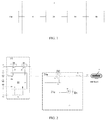
- An embodiment of the present disclosure provides a battery control circuit 1, as shown in FIG. 1 , including a switch control circuit 10, a voltage conversion circuit 20, and a port 30.
- the switch control circuit 10 is configured to control turning-on and turning-off of a battery cell Bat and the voltage conversion circuit 20.
- One terminal of the voltage conversion circuit 20 is connected to the switch control circuit 10, and the other terminal is connected to the port 30.
- the port 30 is configured to connect an external device 40.
- the voltage conversion circuit 20 is configured to convert a voltage of one of them and the converted voltage is used to charge the other one of them.
- the voltage conversion circuit 20 is a buck-boost circuit 20a.
- the external device 40 can be either a load or a power source, that is, the port 30 of the battery control circuit 1 can be connected to a load or a power source.
- the buck-boost circuit 20a is configured to reduce a cell voltage to a load charging voltage Vout to charge the load.
- the buck-boost circuit 20a is configured to boost the power supply voltage to a cell charging voltage to charge the battery cell Bat.
- the buck-boost circuit 20a includes: a first switch, a second switch, an energy storage inductor L1, and a buck-boost controller 21a.
- a first terminal of the switch control circuit 10 is connected to the battery cell Bat.
- One terminal of the second switch is connected to a second terminal of the switch control circuit 10, and the other terminal is connected to one terminal of the energy storage inductor L1 and one terminal of the first switch.
- the other terminal of the energy storage inductor L1 is connected to the port 30.
- the other terminal of the first switch is grounded, and the buck-boost controller 21a is configured to control turning-on and turning-off of the first switch and the second switch.
- the first switch is nMOSFET Q1
- the second switch is nMOSFET Q2.
- a drain of Q2 is connected to a source of Q3, a source of Q2 is connected to one terminal of the energy storage inductor L1 and a drain of Ql, and a source of Q1 is grounded.
- a gate of Q1 and a gate of Q2 are respectively connected to control pins LO and HO of the buck-boost controller 21a.
- the other terminal of the energy storage inductor L1 is connected to the port 30.
- the switch control circuit 10 includes: a switch controller 11, a third switch, and a fourth switch.
- the third switch is nMOSFET Q3, and the fourth switch is nMOSFET Q4.
- a source of Q4 is connected to a positive electrode of the battery cell Bat, and a negative electrode of the battery cell Bat is grounded.
- Q3 and Q4 are connected back-to-back, and a drain of Q4 is connected to a drain of Q3.
- the source of Q4 receives a cell voltage
- the source of Q3 outputs the cell voltage.
- the source of Q3 receives a cell charging voltage
- the source of Q4 outputs the cell charging voltage.
- a gate of Q3 and a gate of Q4 are respectively connected to two control pins of the switch controller 11: CHG and DSG.
- the battery cell Bat is also connected to VC1, VC2 and VC3 pins of the switch controller 11.
- a current detection resistor Rs is connected between the SRP and SRN pins of the switch controller 11.
- the CHG pin of the switch controller 11 maintains a low-level output, and Q4 is in a turning-off state.
- DSG pin maintains a high-level output, and Q3 is in a turning-on state.
- the LO pin of the buck-boost controller 21 a maintains a low-level output, and Q1 is in a turning-off state.
- the HO pin of the buck-boost controller 21a outputs pulse signals.
- Q2 is controlled to be turned on.
- the cell voltage passes through the parasitic diode D4 of Q4 and Q3 and is output at the source of Q3.
- the cell voltage output by the source of Q3 drops to the load charging voltage Vout after passing through Q2 and the energy storage inductor L1.
- the load charging voltage Vout charges a load through the port 30.
- the cell voltage output by the source of Q3 also charges the energy storage inductor L1 through Q2.
- Q2 is controlled to be turned off.
- the energy storage inductor L1, the parasitic diode D1 of Q1 , and the load form a loop.
- the load charging voltage Vout output by the energy storage inductor L1 continues to charge the load through port 30 to realize a step-down charging of the load.
- the DSG pin of the switch controller 11 When the port 30 is connected to a power supply, the DSG pin of the switch controller 11 maintains a low-level output, and Q3 is in a turning-off state.
- the CHG pin maintains a high-level output, and Q4 is in a turning-on state.
- the HO pin of the buck-boost controller 21a maintains a low-level output, and Q2 is in a turning-off state.
- the LO pin of the buck-boost controller 21a outputs pulse signals.
- Q1 When the LO pin outputs a high level, Q1 is controlled to be turned on.
- a power supply voltage rises to a cell charging voltage after passing through the energy storage inductor L1.
- the cell charging voltage charges the battery cell Bat through the parasitic diode D2 of Q2, the parasitic diode D3 of Q3, and Q4.
- the power supply charges the energy storage inductor L1 at a same time.
- Q1 When the LO pin outputs a low level, Q1 is controlled to be turned off.
- the cell charging voltage output by the energy storage inductor L1 charges the battery cell Bat through the parasitic diode D2 of Q2, the parasitic diode D3 of Q3, and Q4, so as to realize a boost charging of the battery cell Bat.
- the port 30 is a USB interface
- the USB interface can be any type of USB interface, such as but not limited to a USB micro interface, a USB mini-interface, and a USB type C interface.
- charging is achieved through two ports, that is, a battery cell charges a load through one port, a power source charges the battery cell through the other port.
- two supporting charging cables are required.
- one port of the battery control circuit 1 can be connected to both a load and a power supply. Through the port and a supporting charging cable, a bidirectional charging can be realized. That is, the battery cell charges the load, and the power supply charges the battery cell.
- circuit structure in the present embodiment is simpler, cost is lowered, usage is more convenient and simpler, and customer experience is improved.
- the above is only an exemplary description, and the present embodiment is not limited thereto.
- the first switch, the second switch, the third switch, and the fourth switch are not limited to nMOSFETs, and other unidirectional switching elements connected in parallel with a reverse bypass can also be used.
- the battery control circuit 1 may include a plurality of the buck-boost circuits 20a. One terminal of each buck-boost circuit 20a is connected to the switch control circuit 10, and the other terminal is connected to a port 30. Each port 30 can be connected to a load or a power source. Therefore, the battery control circuit 1 can simultaneously charge multiple loads and can also use multiple power sources to simultaneously charge the battery cell.
- a switch control circuit 10 in the present embodiment includes: a third switch, a fourth switch, and a switch controller 11.
- One terminal of the fourth switch is connected to the battery cell Bat, and the other terminal of the fourth switch is connected to one terminal of the third switch.
- the switch controller 11 is configured to control turning-on and turning-off of the third switch and the fourth switch, so that the other terminal of the third switch outputs a cell voltage.
- the buck-boost circuit 20a includes a fifth switch and the energy storage inductor L1.
- One terminal of the fifth switch is connected to the other terminal of the third switch and one terminal of the energy storage inductor L1, and the other terminal of the fifth switch is grounded.
- the other terminal of the energy storage inductor L1 is connected to the port 30.
- the buck-boost controller 21a is configured to control turning-on and turning-off of the fifth switch.
- the third switch of the switch control circuit 10 is an nMOSFET Q3, and the fourth switch is an nMOSFET Q4.
- a source of Q4 is connected to a positive electrode of the battery cell Bat, and a negative electrode of the battery cell Bat is grounded.
- Q3 and Q4 are connected back-to-back, and a drain of Q4 is connected to a drain of Q3.
- the source of Q4 receives a cell voltage, and the source of Q3 outputs the cell voltage.
- the source of Q3 receives a cell charging voltage, and the source of Q4 outputs the cell charging voltage.
- a gate of Q3 and a gate of Q4 are respectively connected to two control pins of the switch controller 11: CHG and DSG.
- the battery cell Bat is also connected to VC1, VC2 and VC3 pins of the switch controller 11.
- a current detection resistor Rs is connected between SRP and SRN pins of the switch controller 11.
- the fifth switch of the buck-boost circuit 20a is an nMOSFET Q5.
- a drain of Q5 is connected to the source of Q3 and one terminal of the energy storage inductor L1, and a source of Q5 is grounded.
- the other terminal of the energy storage inductor L1 is connected to the port 30.
- a gate of Q5 is connected to a control pin LO of the switch controller 11.
- the CHG pin of the switch controller 11 maintains a low-level output and Q4 is in a turning-off state.
- the LO pin maintains a low-level output, and Q5 is in a turning-off state.
- the DSG pin of the switch controller 11 outputs pulse signals.
- Q3 is controlled to be turned on.
- the cell voltage passes through the parasitic diode D4 of Q4 and Q3 and is output at the source of Q3.
- the cell voltage output by the source of Q3 drops to the load charging voltage Vout through the energy storage inductor L1, and the load charging voltage Vout charges the load through the port 30.
- the cell voltage output by the source of Q3 also charges the energy storage inductor L1.
- Q3 is controlled to be turned off.
- the energy storage inductor L1, the parasitic diode D5 of Q5, and the load form a loop.
- the load charging voltage Vout output by the energy storage inductor L1 continues to charge the load through the port 30 to realize a step-down charging of the load.
- the DSG pin of the switch controller 11 When the port 30 is connected to a power supply, the DSG pin of the switch controller 11 maintains a low-level output and Q3 is in a turning-off state; the CHG pin maintains a high-level output and Q4 is in a turning-on state.
- the LO pin of the switch controller 11 outputs pulse signals.
- Q5 When the LO pin outputs a high level, Q5 is controlled to be turned on.
- the power supply voltage rises to a cell charging voltage through the energy storage inductor L1, and the cell charging voltage charges the battery cell Bat through the parasitic diode D3 of Q3 and Q4.
- the power supply charges the energy storage inductor L1 at a same time.
- Q5 When the LO pin outputs a low level, Q5 is controlled to be turned off.
- the cell charging voltage output by the energy storage inductor L1 charges the battery cell Bat through the parasitic diode D3 of Q3 and Q4, so as to realize a boost charging of the battery cell Bat.
- the battery control circuit in the present embodiment can also realize a bidirectional charging through a port and a supporting charging cable, that is, the battery cell charges a load, and a power source charges a battery cell.
- circuit structure in the present embodiment is simpler, the cost is lower, use is more convenient and simpler, and customer experience is improved.
- the circuit structure shares a controller and a switch with the switch control circuit 10.
- a buck-boost controller and a switch are omitted in the present embodiment, thereby further reducing cost and simplifying circuit structure.
- the external device 40 is a load.
- the voltage conversion circuit 20 is a step-down circuit 20b.
- the step-down circuit 20b is configured to reduce the cell voltage to the load charging voltage Vout to charge the load.
- a first terminal of the switch control circuit 10 is connected to the battery cell Bat.
- a second terminal of the switch control circuit 10 is configured to output a cell voltage.
- An input terminal of the step-down circuit 20b is connected to the second terminal of the switch control circuit 10.
- An output terminal of the step-down circuit 20b is connected to the port 30 for stepping down and outputting the cell voltage.
- the step-down circuit 20b in the present embodiment includes a step-down controller 21b, a second switch Q2, a freewheeling diode Ds and the energy storage inductor L1, which is equivalent to replacing Q1 in FIG. 2 with the freewheeling diode Ds.
- a drain of Q2 is connected to a source of Q3, and the source is connected to one terminal of the energy storage inductor L1 and a cathode of the freewheeling diode.
- the other terminal of the energy storage inductor L1 is connected to the port 30.
- An anode of the freewheeling diode is grounded.
- a gate of Q2 is connected to a pin HO of the step-down controller 21b.
- the CHG pin of the switch controller 11 when the battery control circuit 1 is working, the CHG pin of the switch controller 11 maintains a low-level output, and Q4 is in a turning-off state.
- the DSG pin maintains a high-level output, and Q3 is in a turning-on state.
- the HO pin of the buck-boost controller 21a outputs pulse signals.
- Q2 When the HO pin outputs a high level, Q2 is controlled to be turned on.
- a cell voltage passes through the parasitic diode D4 of Q4 and Q3 and is output at the source of Q3.
- the cell voltage output by the source of Q3 drops to the load charging voltage Vout after passing through Q2 and the energy storage inductor L1, and the load charging voltage Vout charges the load through the port 30.
- the cell voltage output by the source of Q3 also charges the energy storage inductor L1 through Q2.
- Q2 When the HO pin outputs a low level, Q2 is controlled to be turned off.
- the energy storage inductor L1, the freewheeling diode , and the load form a loop.
- the load charging voltage Vout output by the energy storage inductor L1 continues to charge the load through the port 30 to realize a step-down charging of the load.
- the battery control circuit 1 in the present embodiment can charge a load through the port 30 and is suitable for unidirectional charging scenarios where only a load needs to be charged from a battery, and the battery does not need to be charged from a power source.
- circuit structure in the present embodiment is simpler, and cost is further reduced.
- the battery control circuit 1 in the present embodiment includes the energy storage inductor L1 and a freewheeling diode.
- the switch control circuit 10 includes a third switch, a fourth switch, and a switch controller 11. One terminal of the fourth switch is connected to the battery cell Bat, and the other terminal of the fourth switch is connected to one terminal of the third switch.
- the switch controller 11 is configured to control turning-on and turning-off of the third switch and the fourth switch, so that the other terminal of the third switch outputs a cell voltage.
- the third switch, the energy storage inductor L1, the freewheeling diode, and the switch controller 11 form a step-down circuit 20b. An output terminal of the step-down circuit 20b is connected to the port 30 for stepping down and outputting the cell voltage.
- the step-down circuit 20b only includes the freewheeling diode Ds and the energy storage inductor L1.
- a source of Q3 is connected to one terminal of the energy storage inductor L1 and a cathode of the freewheeling diode.
- the other terminal of the energy storage inductor L1 is connected to the port 30.
- An anode of the freewheeling diode is grounded.
- the CHG pin of the switch controller 11 maintains a low-level output, and Q4 is in a turning-off state.
- the DSG pin of the switch controller 11 outputs pulse signals.
- Q3 When the DSG pin outputs a high level, Q3 is controlled to be turned on.
- a cell voltage passes through the parasitic diode D4 of Q4 and Q3 and is output at the source of Q3.
- the cell voltage output by the source of Q3 drops to the load charging voltage Vout through the energy storage inductor L1.
- the load charging voltage Vout charges the load through the port 30.
- the cell voltage output by the source of Q3 also charges the energy storage inductor L1.
- Q3 When the DSG pin outputs a low level, Q3 is controlled to be turned off.
- the energy storage inductor L1, the freewheeling diode , and the load form a loop.
- the load charging voltage Vout output by the energy storage inductor L1 continues to charge the load through the port 30 to realize a step-down charging of the load.
- the battery control circuit 1 in the present embodiment shares a controller and a switch with the switch control circuit 10. Compared with the previous embodiment, a step-down controller and a switch are omitted in the present embodiment, thereby further reducing cost and simplifying circuit structure.
- the external device 40 is a power source.
- the voltage conversion circuit 20 is a boost circuit 20c for boosting a power supply voltage to a cell charging voltage to charge the battery cell Bat.
- An input terminal of the boost circuit 20c is connected to the port 30 for inputting the power supply voltage.
- An output terminal of the boost circuit 20c is configured to output the battery charging voltage.
- a second terminal of the switch control circuit 10 is connected to the output terminal of the boost circuit 20c.
- a first terminal of the switch control circuit 10 is connected to the battery cell Bat for outputting the cell charging voltage.
- the boost circuit 20c includes a boost controller 21c, a first switch Q1, a freewheeling diode Dj and the energy storage inductor L1, which is equivalent to replacing Q2 in FIG. 1 with the freewheeling diode Dj.
- a cathode of Dj is connected to the source of Q3.
- An anode of Dj is connected to one terminal of the energy storage inductor L1 and a drain of Q1.
- a source of Q1 is grounded.
- the other terminal of the energy storage inductor L1 is connected to the port 30.
- a gate of Q1 is connected to the pin LO of the boost controller 21c.
- the CHG pin of the switch controller 11 when the battery control circuit 1 is working, the CHG pin of the switch controller 11 maintains a high-level output, and Q4 is in a turning-on state.
- the DSG pin maintains a low-level output, and Q3 is in a turning-off state.
- the LO pin of the boost controller 21c outputs pulse signals.
- Q1 When the LO pin outputs a high level, Q1 is controlled to be turned on.
- a power supply voltage Vin rises to a cell charging voltage through the energy storage inductor L1.
- the cell charging voltage charges the battery cell Bat through the freewheeling diode, the parasitic diode D3 of Q3, and Q4.
- the power supply charges the energy storage inductor L1 at a same time.
- Q1 When the LO pin outputs a low level, Q1 is controlled to be turned off.
- the energy storage inductor L1 charges the battery cell Bat through the freewheeling diode, the parasitic diode D3 of Q3, and Q4 to realize a boost charging of the battery cell Bat.
- the battery control circuit 1 in the present embodiment can charge the battery cell through a port and is suitable for unidirectional charging scenarios where only a battery cell needs to be charged by a power source, and the battery cell does not need to charge a load.
- circuit structure in the present embodiment is simpler, and cost is further reduced.
- a battery 2 includes a battery cell Bat, a housing 3, and the battery control circuit 1.
- the battery cell Bat and the battery control circuit 1 are packaged in the housing 3.
- the battery control circuit 1 may be the battery control circuit 1 described in any of the above embodiments.
- the battery control circuit 1 further includes a power supply port 50 configured to connect an electrical device 60. Under a control of the switch control circuit 10, a cell voltage is supplied to the electrical device 60 through the power supply port 50.
- the switch control circuit 10 of the battery control circuit 1 includes: a third switch, a fourth switch, a sixth switch, and the switch controller 11. One terminal of the fourth switch is connected to the battery cell Bat, and the other terminal of the fourth switch is connected to one terminal of the third switch. One terminal of the sixth switch is connected to the other terminal of the third switch. The other terminal of the sixth switch is connected to the power supply port 50.
- the switch controller 11 is configured to control turning-on and turning-off of the third switch, the fourth switch and the sixth switch.
- the third switch is nMOSFET Q3, the fourth switch is nMOSFET Q4, and the sixth switch is nMOSFET Q6.
- a source of Q4 is connected to an anode of the battery cell Bat. A cathode of the battery cell Bat is grounded.
- Q3 and Q4 are connected back-to-back.
- a drain of Q4 is connected to a drain of Q3.
- a gate of Q3 and a gate of Q4 are respectively connected to two control pins of the switch controller 11: CHG and DSG.
- a drain of Q6 is connected to a source of Q3.
- a source of Q6 is connected to the power supply port 50.
- a gate of Q6 is connected to a control pin CTRL of the switch controller 11.
- the CHG pin of the switch controller 11 when the battery 2 is working, the CHG pin of the switch controller 11 maintains a low-level output, and Q4 is in a turning-off state.
- the DSG pin maintains a high-level output, and Q3 is in a turning-on state.
- a cell voltage is output through the parasitic diode D4 of Q4 and Q3.
- the switch controller 11 detects a remaining power of the battery Bat. When the remaining power of the battery Bat is greater than a threshold, the CTRL pin of the switch controller 11 outputs a high level, Q6 is turned on.
- the cell voltage supplies power to the electrical device 60 through Q6 and the power supply port 50.
- the CTRL pin When the remaining power of the battery cell Bat is less than or equal to the threshold, the CTRL pin outputs a low level, Q6 is turned off. Power supply to the electrical device 60 is stopped. Although no power is supplied to the electrical device 60 at this time, the cell voltage is still output to the buck-boost circuit 20a, and the remaining power of the cell can still charge a load.
- a battery cell For a UAV, which is an electrical device with high requirements for power supply safety, when a remaining power of a battery cell is less than a threshold, for example, 30% of a total power, if power to the UAV is continuously supplied, a battery may be too low to meet a voyage range of the UAV, thereby affecting flight safety of the UAV. Therefore, in this case, the battery cell can no longer supply power to the UAV. However, if the remaining power is not used, it will cause a waste of energy.
- the battery 2 in the present embodiment also has the port 30 for charging a load. For a battery cell whose remaining power is less than the threshold, the remaining power can continue to charge the load. Therefore, a battery can meet the power needs of the UAV and can also charge a load such as a mobile device. Users no longer need to carry a separate charging power source for the mobile device.
- a threshold for example, 30% of a total power
- a UAV 4 includes a body 41 and a battery 2.
- the body 41 is provided with a slot 411 configured to install the battery 2.
- the slot 411 is provided with a power receiving port 412 configured to connect a power supply port 50 of the battery 2.
- the battery 2 supplies power to the body 41 through the power supply port 50 and the power receiving port 412.
Applications Claiming Priority (1)
| Application Number | Priority Date | Filing Date | Title |
|---|---|---|---|
| PCT/CN2018/112725 WO2020087284A1 (fr) | 2018-10-30 | 2018-10-30 | Circuit de commande de batterie, batterie et véhicule aérien sans pilote |
Publications (1)
| Publication Number | Publication Date |
|---|---|
| EP3876335A1 true EP3876335A1 (fr) | 2021-09-08 |
Family
ID=69746138
Family Applications (1)
| Application Number | Title | Priority Date | Filing Date |
|---|---|---|---|
| EP18938391.2A Withdrawn EP3876335A1 (fr) | 2018-10-30 | 2018-10-30 | Circuit de commande de batterie, batterie et véhicule aérien sans pilote |
Country Status (4)
| Country | Link |
|---|---|
| US (1) | US20210249870A1 (fr) |
| EP (1) | EP3876335A1 (fr) |
| CN (1) | CN110892603A (fr) |
| WO (1) | WO2020087284A1 (fr) |
Families Citing this family (2)
| Publication number | Priority date | Publication date | Assignee | Title |
|---|---|---|---|---|
| CN116762252A (zh) * | 2021-01-15 | 2023-09-15 | 菲利普莫里斯生产公司 | 用于可再充电电子装置的智能充电器 |
| CN115208009B (zh) * | 2022-07-07 | 2024-04-30 | 深圳拓邦股份有限公司 | 电池保护电路及电器 |
Family Cites Families (7)
| Publication number | Priority date | Publication date | Assignee | Title |
|---|---|---|---|---|
| CN201266996Y (zh) * | 2008-06-25 | 2009-07-01 | 比亚迪股份有限公司 | 一种手机电池及具有该手机电池的手机 |
| JP5596521B2 (ja) * | 2010-12-03 | 2014-09-24 | 株式会社Nttファシリティーズ | 直流給電システム及び双方向電力変換装置 |
| CN203368093U (zh) * | 2013-07-26 | 2013-12-25 | 深圳市恒盛利科技有限公司 | 共用充放电接口的移动电源 |
| CN104158255B (zh) * | 2014-08-20 | 2017-09-26 | 矽力杰半导体技术(杭州)有限公司 | 充放电管理系统及其应用的移动电源 |
| CN106026249A (zh) * | 2016-06-22 | 2016-10-12 | 深圳众思科技有限公司 | 电池低压工作电路及其控制方法 |
| CN106253399B (zh) * | 2016-08-24 | 2019-01-01 | 天津市天楚科技有限公司 | 一种移动电源 |
| CN107124906B (zh) * | 2016-09-26 | 2019-01-29 | 深圳市大疆创新科技有限公司 | 一种电池的固持组件、无人机及充电器 |
-
2018
- 2018-10-30 CN CN201880038717.1A patent/CN110892603A/zh active Pending
- 2018-10-30 WO PCT/CN2018/112725 patent/WO2020087284A1/fr unknown
- 2018-10-30 EP EP18938391.2A patent/EP3876335A1/fr not_active Withdrawn
-
2021
- 2021-04-27 US US17/242,292 patent/US20210249870A1/en not_active Abandoned
Also Published As
| Publication number | Publication date |
|---|---|
| US20210249870A1 (en) | 2021-08-12 |
| WO2020087284A1 (fr) | 2020-05-07 |
| CN110892603A (zh) | 2020-03-17 |
Similar Documents
| Publication | Publication Date | Title |
|---|---|---|
| US7994756B2 (en) | Power distribution circuit for use in a portable telecommunications device | |
| US11545896B1 (en) | Power supply conversion structure and electronic device including the same | |
| US11522466B1 (en) | Power conversion structure, power conversion method, electronic device including power conversion structure, and chip unit | |
| US20210249870A1 (en) | Battery control circuit, battery and unmanned aerial vehicle | |
| CN109904913B (zh) | 一种充电设备及其快速充电电路 | |
| CN102118052B (zh) | 电源管理系统 | |
| CN104767252A (zh) | 平板电脑 | |
| CN111049222A (zh) | 电源装置 | |
| US11588391B1 (en) | Power conversion structure, system, method, electronic device including power conversion structure, and chip unit | |
| CN110138217B (zh) | 一种三端口dc-dc变换器及其控制方法 | |
| KR102196926B1 (ko) | 복수의 배터리 셀의 직렬, 병렬 전환이 가능한 전력관리장치 | |
| CN101795014B (zh) | 一种移动终端对外部设备的供电装置及方法 | |
| CN113794373B (zh) | 多电平直流转换器及供电系统 | |
| CN113013956A (zh) | 充放电电路和电子设备 | |
| WO2015156597A1 (fr) | Convertisseur de puissance pour éliminer des ondulations | |
| CN116388350B (zh) | 充电控制方法、储能设备和可读存储介质 | |
| CN113067385A (zh) | 电池单元充放电装置 | |
| CN211266526U (zh) | 电源装置 | |
| CN115699500A (zh) | 用于控制电芯的电路和电子设备 | |
| CN114094684B (zh) | 一种用于给电池充电的架构 | |
| WO2021104373A1 (fr) | Circuit de commande de commutation à batteries multiples, appareil et système, et procédé de commande | |
| CN113991782A (zh) | 供电系统 | |
| CN112751387A (zh) | 变流系统及具有其的电池系统 | |
| CN220914951U (zh) | 储能电源和储能系统 | |
| CN212517041U (zh) | 一种电表拉合闸电路 |
Legal Events
| Date | Code | Title | Description |
|---|---|---|---|
| STAA | Information on the status of an ep patent application or granted ep patent |
Free format text: STATUS: THE INTERNATIONAL PUBLICATION HAS BEEN MADE |
|
| PUAI | Public reference made under article 153(3) epc to a published international application that has entered the european phase |
Free format text: ORIGINAL CODE: 0009012 |
|
| STAA | Information on the status of an ep patent application or granted ep patent |
Free format text: STATUS: REQUEST FOR EXAMINATION WAS MADE |
|
| 17P | Request for examination filed |
Effective date: 20210514 |
|
| AK | Designated contracting states |
Kind code of ref document: A1 Designated state(s): AL AT BE BG CH CY CZ DE DK EE ES FI FR GB GR HR HU IE IS IT LI LT LU LV MC MK MT NL NO PL PT RO RS SE SI SK SM TR |
|
| STAA | Information on the status of an ep patent application or granted ep patent |
Free format text: STATUS: THE APPLICATION HAS BEEN WITHDRAWN |
|
| 18W | Application withdrawn |
Effective date: 20211029 |