EP3875939B1 - Dynamic characteristic measurement device - Google Patents
Dynamic characteristic measurement device Download PDFInfo
- Publication number
- EP3875939B1 EP3875939B1 EP19886599.0A EP19886599A EP3875939B1 EP 3875939 B1 EP3875939 B1 EP 3875939B1 EP 19886599 A EP19886599 A EP 19886599A EP 3875939 B1 EP3875939 B1 EP 3875939B1
- Authority
- EP
- European Patent Office
- Prior art keywords
- measurement device
- characteristic measurement
- dynamic characteristic
- dynamic
- vibration
- Prior art date
- Legal status (The legal status is an assumption and is not a legal conclusion. Google has not performed a legal analysis and makes no representation as to the accuracy of the status listed.)
- Active
Links
Images



Classifications
-
- G—PHYSICS
- G01—MEASURING; TESTING
- G01M—TESTING STATIC OR DYNAMIC BALANCE OF MACHINES OR STRUCTURES; TESTING OF STRUCTURES OR APPARATUS, NOT OTHERWISE PROVIDED FOR
- G01M7/00—Vibration-testing of structures; Shock-testing of structures
- G01M7/02—Vibration-testing by means of a shake table
- G01M7/022—Vibration control arrangements, e.g. for generating random vibrations
-
- G—PHYSICS
- G01—MEASURING; TESTING
- G01M—TESTING STATIC OR DYNAMIC BALANCE OF MACHINES OR STRUCTURES; TESTING OF STRUCTURES OR APPARATUS, NOT OTHERWISE PROVIDED FOR
- G01M7/00—Vibration-testing of structures; Shock-testing of structures
- G01M7/02—Vibration-testing by means of a shake table
- G01M7/025—Measuring arrangements
-
- G—PHYSICS
- G01—MEASURING; TESTING
- G01M—TESTING STATIC OR DYNAMIC BALANCE OF MACHINES OR STRUCTURES; TESTING OF STRUCTURES OR APPARATUS, NOT OTHERWISE PROVIDED FOR
- G01M7/00—Vibration-testing of structures; Shock-testing of structures
- G01M7/02—Vibration-testing by means of a shake table
- G01M7/027—Specimen mounting arrangements, e.g. table head adapters
-
- G—PHYSICS
- G01—MEASURING; TESTING
- G01N—INVESTIGATING OR ANALYSING MATERIALS BY DETERMINING THEIR CHEMICAL OR PHYSICAL PROPERTIES
- G01N3/00—Investigating strength properties of solid materials by application of mechanical stress
- G01N3/32—Investigating strength properties of solid materials by application of mechanical stress by applying repeated or pulsating forces
-
- G—PHYSICS
- G01—MEASURING; TESTING
- G01N—INVESTIGATING OR ANALYSING MATERIALS BY DETERMINING THEIR CHEMICAL OR PHYSICAL PROPERTIES
- G01N3/00—Investigating strength properties of solid materials by application of mechanical stress
- G01N3/32—Investigating strength properties of solid materials by application of mechanical stress by applying repeated or pulsating forces
- G01N3/38—Investigating strength properties of solid materials by application of mechanical stress by applying repeated or pulsating forces generated by electromagnetic means
-
- G—PHYSICS
- G01—MEASURING; TESTING
- G01N—INVESTIGATING OR ANALYSING MATERIALS BY DETERMINING THEIR CHEMICAL OR PHYSICAL PROPERTIES
- G01N33/00—Investigating or analysing materials by specific methods not covered by groups G01N1/00 - G01N31/00
- G01N33/44—Resins; Plastics; Rubber; Leather
- G01N33/445—Rubber
Definitions
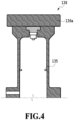
- Fig. 4 is a cross-sectional view illustrating the resonant jig 136 also serving as the static load measurement unit of the dynamic characteristic measurement device 100 shown in Figs. 1 to 3 .
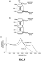
- Fig. 5A is a schematic diagram illustrating a state of attaching a rigid jig 536 to a conventional electrodynamic vibrator vibrating table 132.
- Fig. 5B is a schematic diagram illustrating a state of attaching the resonant jig 136 to the electrodynamic vibrator vibrating table 132.
- Fig. 5C is a diagram illustrating a comparison between frequency characteristics in the states of attaching any of the rigid jig 536 and the resonant jig 136.
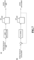
- the position of the electrodynamic vibrator vibrating table 132 is measured by using the position sensor 137 and this displacement signal is used as a signal value as illustrated in Fig. 7B .
- a PID control unit can perform the feedback control of the electrodynamic vibrator vibrating table 132 by using a closed loop, thereby controlling an accurate position of the electrodynamic vibrator vibrating table 132.
- This position control function makes it possible to measure the static spring constant of the object under test.
- the power amplifier housing 230 is controlled by a signal from the vibrator operating panel 213 of the main control device 210, and is configured to control operations of the electrodynamic vibrator vibrating table 132 of the electrodynamic vibrator 113 of the dynamic characteristic measurement device 100, for example.
Landscapes
- Physics & Mathematics (AREA)
- General Physics & Mathematics (AREA)
- Health & Medical Sciences (AREA)
- Life Sciences & Earth Sciences (AREA)
- Chemical & Material Sciences (AREA)
- Analytical Chemistry (AREA)
- Pathology (AREA)
- Immunology (AREA)
- General Health & Medical Sciences (AREA)
- Biochemistry (AREA)
- Electromagnetism (AREA)
- Engineering & Computer Science (AREA)
- Medicinal Chemistry (AREA)
- Food Science & Technology (AREA)
- Measurement Of Mechanical Vibrations Or Ultrasonic Waves (AREA)
- Investigating Strength Of Materials By Application Of Mechanical Stress (AREA)
- Other Investigation Or Analysis Of Materials By Electrical Means (AREA)
- Testing Or Measuring Of Semiconductors Or The Like (AREA)
- Testing Electric Properties And Detecting Electric Faults (AREA)
Description
- The present invention relates to a dynamic characteristic measurement device, or more specifically, to a dynamic characteristic measurement device to measure dynamic characteristics of a rubber isolator for an automobile and the like.
- Dynamic characteristics of a rubber isolator are key factors for determining vibration isolation, ride comfort, steering stability, kinematic performances, sound isolation, and energy saving performances of an automobile and the like. Control of the dynamic characteristics is an important issue not only for rubber isolator manufacturers but also for automobile manufacturers. The dynamic performances of the rubber isolators are influenced by frequencies, environmental temperatures, amplitudes, preloads, and the like. Accordingly, advanced design techniques, measurement techniques, and signal processing techniques are essential for achieving measurements at high accuracy.
- As for dynamic properties of rubber isolators, there have been strong demands for improvements in dynamic properties of products and enhancement in management levels with a central focus mainly on rubber isolators for automobiles. Accordingly, testing methods have been standardized as defined in SRIS 3503 (The Society of Rubber Science and Technology, Japan Standards), for example. Note that the dynamic properties referred to herein are collective terms including a storage spring constant, a loss spring constant, an absolute spring constant, an attenuation coefficient, a loss coefficient, and a phase angle.
- PTL 1 describes a dynamic characteristic testing device configured to install a vibrator, a test piece, and a load detector in series between a base member and a support member, which is placed on the base member via an elastic body, in such a way as to apply a dynamic load from the vibrator to the test piece, and to set a mass on the support member side and a spring constant of the elastic body such that a resonance frequency to be determined by the mass on the support member side supported by the base member via the elastic body and the spring constant of the elastic body becomes sufficiently smaller than a vibration frequency by the vibrator.
- Meanwhile, PTL 2 describes a dynamic characteristic measurement device for a rubber isolator, which is a measurement device configured to perform a dynamic characteristic measurement by using a load cell while repeatedly applying loads to a test piece such as a rubber isolator, which adopts a piezoelectric element type load cell prepared by arranging three or more piezoelectric elements in parallel as the load cell.
- In the meantime, PTL 3 describes a dynamic characteristic measurement device in which a rubber isolator is sandwiched in a direction of vibration between a first support member and a second support member that are fixed to a base via an elastic body, and the first support body is disposed on an opposite side of a vibration side and has a sufficient mass for not being influenced by the vibration. Here, a pressing device applies a constant load from outside of the elastic body to the rubber isolator via the elastic body in a direction that one of the first support member and the second member approaches the other one of the first support member and the second member, and the rubber isolator is vibrated by a vibrator from outside.
- On the other hand, hybrid type vehicles and electric vehicles which utilize rotatory power of electric motors have been rapidly diffused in recent years in addition to conventional vehicles that utilize gasoline engines. A vibration range of such an electric motor exceeds a vibration range of a conventional reciprocating engine around 1.5 kHz and reaches a high-frequency range up to 5 kHz. Particularly, in order to analyze factors including noise, vibration, harshness (NVH), and the like which disturb drivers and passengers, there is a growing need for measuring dynamic vibration characteristic data in a high-frequency range up to 3 kHz regarding a rubber isolator used in a vehicle that mounts the aforementioned electric motor.
-
US 6 813 960 B1 discloses a characteristic measurement device but does not disclose an elastic body and a support body with a resonance frequency of at least 3 kHz generated by the shape of the support part. - Also
JP 2007 271268 A -
- PTL 1:
Japanese Patent Publication No. 61-22251 - PTL 2:
Japanese Patent Laid-Open No. 64-13434 - PTL 3:
Japanese Patent Laid-Open No. 2007-271268 - However, the conventional dynamic characteristic measurement apparatus as described in PTL 1 or 2 has the upper limit of the vibration frequency of about 1.5 kHz due to its structure, and cannot therefore deal with the vibration in the aforementioned high-frequency range.
- In the meantime, although PTL 3 describes the dynamic characteristic measurement device that embeds the vibrator capable of applying the vibration up to about 5 kHz and the mechanism for applying the constant load by using the pressing device in order to deal with the high frequency. However, PTL 3 does not include a description as to whether or not the device can perform an accurate measurement up to a high frequency.
- In other words, the measurement of the dynamic characteristics in the high-frequency vibration range has a problem that it is difficult to perform an accurate measurement in a range around the resonance frequency unless a resonance point of a frame is set higher than a range of the measurement frequency. Meanwhile, particularly in the case of a rubber isolator for an automobile and the like, it is necessary to measure the dynamic characteristics in a state of application of a high load (a preload) on the assumption of a state of an actual vehicle. However, in the state of applying the preload as mentioned above, it is necessary to broaden a measurement range in a measurement with a load detector. Hence, there is a problem of a difficulty in measuring a small dynamic load at a high frequency. On the other hand, while a high vibration capacity and a high amplitude which are proportional to a square of the frequency are required in the high-frequency vibration range, a resonance frequency drops in a case where a weight is reduced in order to activate an electrodynamic vibrator at a high speed. This drop in vibration capacity also leads to a problem of a difficulty in obtaining a required vibration amplitude.
- Accordingly, it is an object of the present invention to provide a dynamic characteristic measurement device, which is capable of measuring a small dynamic load in a state of applying a preload while eliminating an influence of a resonance frequency of a frame even in a high-frequency vibration range up to 3 kHz, and of accurately measuring dynamic vibration characteristics of a rubber isolator and the like in the high-frequency vibration range by increasing a level of vibration of an object under test.
- This object is achieved by a dynamic characteristic measurement device according to claim 1.
- Further improvements are given in the dependent claims.
- Moreover, the preload may be applied together with the electrodynamic vibrator and air provided on the electrodynamic vibrator side.
- According to the present invention, it is possible to provide a dynamic characteristic measurement device, which is capable of measuring a small dynamic load in a state of applying a preload while eliminating an influence of a resonance frequency of a frame even in a high-frequency vibration range up to 3 kHz, and of accurately measuring dynamic vibration characteristics of a rubber isolator and the like in the high-frequency vibration range by increasing a level of vibration of an object under test.
-
- [
Fig. 1] Fig. 1 is a perspective view illustrating an example of a dynamic characteristic measurement device according to the present invention. - [
Fig. 2] Fig. 2A is a partial cross-sectional view illustrating the dynamic characteristic measurement device shown inFig. 1 and being viewed from a front face, andFig. 2B is an enlarged cross-sectional view illustrating a portion IIb shown inFig. 2A . - [
Fig. 3] Fig. 3 is a side view illustrating a state of stretching support pillars of the dynamic characteristic measurement device shown inFig. 2A . - [
Fig. 4] Fig. 4 is a cross-sectional view illustrating a resonant jig that also serves as a static load measurement unit of the dynamic characteristic measurement device shown inFigs. 1 to 3 . - [
Fig. 5] Fig. 5A is a schematic diagram illustrating a state of attaching a rigid jig to a conventional electrodynamic vibrator vibrating table,Fig. 5B is a schematic diagram illustrating a state of attaching the resonant jig to the electrodynamic vibrator vibrating table, andFig. 5C is a diagram illustrating a comparison between frequency characteristics in the states of attaching any of the rigid jig and the resonant jig. - [
Fig. 6] Fig 6 is a system block diagram of a control system applied to the dynamic characteristic measurement device shown inFigs. 1 to 3 . - [
Fig. 7] Fig. 7A is a block diagram illustrating open loop control of a conventional electrodynamic vibrator vibrating table andFig. 7B is a block diagram illustrating closed loop feedback control of the electrodynamic vibrator vibrating table. - An embodiment of the present invention will be described below with reference to the drawings.
- Note that the concept of upper and lower positions in the following description corresponds to upper and lower positions in
Fig. 2A , for example, which indicates a relative positional relation between respective components but does not indicate an absolute positional relation therebetween. -
Fig. 1 is a perspective view illustrating an exemplary dynamiccharacteristic measurement device 100 according to the present invention.Fig. 2A is a partial cross-sectional view illustrating the dynamiccharacteristic measurement device 100 shown inFig. 1 and being viewed from a front face, andFig. 2B is an enlarged cross-sectional view illustrating a portion IIb shown inFig. 2A .Fig. 3 is a side view illustrating a state of stretching support pillars of the dynamiccharacteristic measurement device 100 shown inFig. 2A . - In
Fig. 1 to 3 , the dynamiccharacteristic measurement device 100 is a measurement device that measures dynamic properties of a rubber isolator for an automobile and the like, which are standardized as defined in SRIS 3503 (The Society of Rubber Science and Technology, Japan Standards), for example. Note that the dynamic properties referred to herein are collective terms including a storage spring constant, a loss spring constant, an absolute spring constant, an attenuation coefficient, a loss coefficient, and a phase angle. - The dynamic
characteristic measurement device 100 includes abase 110, asupport part 120 that is placed above the base 110 so as to be capable of floating via an elastic body such as anair spring 122 to be described later, and ameasurement unit 130 arranged between the base 110 and thesupport part 120. - The
base 110 includesleg parts 111, air springs 112, anelectrodynamic vibrator 113, and abase mount part 114. - The
leg parts 111 are arranged at positions located on a lower side illustrated inFig. 2A and in contact with a ground, thus fixing the dynamiccharacteristic measurement device 100 to the ground. Here, the dynamiccharacteristic measurement device 100 is fixed to the ground by using fourleg parts 111. However, such an attachment unit is not limited to this configuration as long as the attachment unit can endure outside factors such as earthquakes, because transmission of vibration is prevented by attachment to a body part via the air springs 112 as described below. - Here, four air springs 112 are provided, each of which is arranged between corresponding one of the four
leg parts 111 and the body part of the dynamiccharacteristic measurement device 100. The four air springs 112 are provided in order to prevent transmission of vibration between the ground and the dynamiccharacteristic measurement device 100 in the course of a vibration test. - The
electrodynamic vibrator 113 is attached to thebase mount part 114 of the dynamiccharacteristic measurement device 100 and connected to acontrol system 200 to be described later so as to drive an electrodynamic vibrator vibrating table 132 to be described later. A set of thebase mount part 114 and theelectrodynamic vibrator 113 has a sufficient mass and plays a role for preventing vibration transmission in conjunction with the above-mentioned air springs 112. - The
support part 120 includessupport pillars 121, air springs 122,fasteners 123, acrosshead 124, and anintermediate plate 125. - Here, four
support pillars 121 are arranged above the base 110 so that thecrosshead 124 can be placed above, and are joined to theintermediate plate 125. Note that thesupport pillars 121 of the dynamiccharacteristic measurement device 100 can also be stretched as illustrated inFig. 3 . Thestretchable support pillars 121 as mentioned above make it possible to house and measure a constant temperature bath into themeasurement unit 130, and to measure anobject 131 under test which is large in size. - Each
air spring 122 is an elastic body that is placed above theintermediate plate 125. Provision of the air springs 122 makes it possible to establish a floating state of blocking transmission of vibration such as resonance between thecrosshead 124 placed above the air springs 122 and the base 110 in a state of high-frequency vibration and the like. Although the dynamiccharacteristic measurement device 100 is provided with eight air springs 122 as illustrated inFig. 1 , the present invention is not limited to this configuration. A different quantity of the air springs 122 may be provided as long as the floating state can be established therewith. - The
fasteners 123 are driven by a hydraulic pressure, an air pressure, or the like. Thefasteners 123 are provided in order to fix thecrosshead 124 to theintermediate plate 125 and to release the floating state. Here, the case of releasing the floating state may conceivably involve a case in which thebase mount part 114, thesupport pillars 121, theintermediate plate 125, and thecrosshead 124 are rigidly joined to one another to have high rigidity, and the object under test is subjected to a measurement of its static spring constant, a measurement at a low vibration frequency such as a frequency in a range from about 100 to 150 Hz inclusive, and so forth. Meanwhile, thefasteners 123 are installed at four positions in this case as illustrated inFig. 1 . However, the number of thefasteners 123 installed is not limited to this number as long as sufficient coupling rigidity is available. - The
crosshead 124 is placed above the base 110 so as to be capable of floating via the air springs 122. A vibration range of electric motors for hybrid-type vehicles and electric vehicles reaches a high-frequency range in excess of 1.5 kHz that represents a vibration range of conventional reciprocating engines. Here, a measurement takes place in a high-frequency vibration range up to 3 kHz. In this case, if a resonance frequency unique to thecrosshead 124 is low, thecrosshead 124 may be resonated during the measurement whereby an accurate measurement is infeasible. Accordingly, the resonance frequency of thecrosshead 124 needs to be set to a higher frequency than a measurement range to be examined. - In the dynamic
characteristic measurement device 100 of the present invention, thecrosshead 124 is formed into such a shape that has a sufficient weight (1500 kg or above) so as to raise the resonance frequency of thecross head 124. Moreover, this shape is formed into a shape close to a cylinder. In addition, the shape has a value of a ratio of a thickness to a diameter (H/D inFig. 2A ) close to 1 (0.7 to 1.3). - First, regarding the weight of the
crosshead 124, the vibration of themeasurement unit 130 cannot be fully blocked if the weight is too low. On the other hand, the resonance frequency cannot be raised if the weight is too high. Accordingly, a certain level of the weight is required. Meanwhile, regarding the shape, the vibration has several modes including longitudinal vibration, bending vibration, swing vibration, and the like, and a probability of the occurrence of resonance along with any of the vibration modes becomes higher in a case where any of the thickness and the diameter is increased. It is therefore possible to raise an average resonance frequency by setting the ratio of the thickness to the diameter to a value close to 1. - As a result of the measurement, the resonance frequency of the
crosshead 124 was successfully set around 4 kHz by adopting the above-described shape. Meanwhile, by using the above-describedcrosshead 124 in the dynamiccharacteristic measurement device 100, it is possible to measure the high-frequency range up to 3 kHz while eliminating an influence of the resonance frequency of thecrosshead 124. - The
measurement unit 130 includes theobject 131 under test, the electrodynamic vibrator vibrating table 132,load washers 133, anaccelerometer 134,distortion meters 135, aresonant jig 136, aposition sensor 137, and a loadwasher attachment block 138. - In the case of the dynamic
characteristic measurement device 100 of the present invention, theobject 131 under test is a rubber isolator for an automobile and the like. Here, the rubber isolator includes a rubber isolator provided with a phase element such as a rubber isolator provided with a mass and a rubber isolator sealing a liquid. Theobject 131 under test is measured by being sandwiched between the electrodynamic vibrator vibrating table 132 and theload washers 133. - The electrodynamic vibrator vibrating table 132 is installed above the
electrodynamic vibrator 113 and is controlled by thecontrol system 200 to be described later. Although illustration is omitted, a vibratingplate 132a and acoil portion 132b are directly coupled to the electrodynamic vibrator vibrating table 132, and a direct-current magnetic field is arranged around them. The electrodynamic vibrator vibrating table 132 is driven by applying an electric current to this coil. Here, the vibration frequency range of theelectrodynamic vibrator 113 is up to 3 kHz. However, the range is not particularly limited to 3 kHz and may be equal to or above 3 kHz. - The
load washers 133 are attached via the loadwasher attachment block 138 to thecrosshead 124 on the opposite side of theelectrodynamic vibrator 113 for theobject 131 under test. Eachload washer 133 is a highly rigid piezoelectric element which has a high response speed and a small measurement threshold. Accordingly, theload washer 133 herein constitutes a dynamic load measuring instrument to measure a dynamic load applied to theobject 131 under test. Note that fourload washers 133 are arranged and installed as illustrated inFig. 2B and an average value thereof is obtained. However, the present invention is not limited to this configuration. - As illustrated in
Fig. 2B , theaccelerometer 134 is attached to flanges on a side of theload washers 133 to which theobject 131 under test is attached. Theaccelerometer 134 is provided in order to calculate a dynamic load from a measured acceleration rate in a case where thecrosshead 124 vibrates, and to accurately measure theobject 131 under test while eliminating an influence of the vibration. Accordingly, the measurement by using theaccelerometer 134 does not have to be carried out in a case where the influence of the vibration of thecrosshead 124 to the measurement accuracy is negligible. - The
resonant jig 136 which also serves as a static load measurement unit is attached to a side of the electrodynamic vibrator vibrating table 132 near theobject 131 under test. Here, theresonant jig 136 also serving as the static load measurement unit will be described by usingFigs. 4 to 5C . -
Fig. 4 is a cross-sectional view illustrating theresonant jig 136 also serving as the static load measurement unit of the dynamiccharacteristic measurement device 100 shown inFigs. 1 to 3 .Fig. 5A is a schematic diagram illustrating a state of attaching arigid jig 536 to a conventional electrodynamic vibrator vibrating table 132.Fig. 5B is a schematic diagram illustrating a state of attaching theresonant jig 136 to the electrodynamic vibrator vibrating table 132.Fig. 5C is a diagram illustrating a comparison between frequency characteristics in the states of attaching any of therigid jig 536 and theresonant jig 136. - As illustrated in
Fig. 4 , thedistortion meters 135 constituting the static load measurement unit are arranged at equal intervals on an inner periphery of theresonant jig 136 having a cylindrical shape here, and are capable of measuring a load in an axial direction. Note that arigid block 136a for attaching theobject 131 under test is provided above theresonant jig 136. Thedistortion meters 135 are provided for the purpose of measuring a static preload and are not affected by a dynamic load from an acceleration rate attributed to a mass of theblock 136a and the like in an averaging procedure and a filtering procedure. In the meantime, thedistortion meters 135 do not always have to be highly responsive. This static load measurement jig also has functions as the resonant jig as described below. However, the present invention is not limited to this configuration. - In the case of the rubber isolator for an automobile and the like, it is necessary to measure the dynamic characteristics in a state of application of a high load (a preload) on the assumption of a state of an actual vehicle. However, in the state of applying the preload as mentioned above, it is necessary to broaden a measurement range in a measurement of a dynamic load. In the case of the high frequency, a displacement of the object under test is reduced and the load is reduced as well. Accordingly, there is a problem a difficulty in measuring the load. Moreover, a performance of the rubber isolator does not have linearly and is therefore difficult to predict. Given the situation, the present invention newly provides the
distortion meters 135 each serving as a static load measuring instrument, and is configured to improve an S/N ratio and to measure the dynamic load accurately by measuring only the dynamic load with theload washers 133 and reducing a measurement range of acharge amplifier 212 in a block diagram illustrated inFig. 6 . - As illustrated in
Fig. 4 , theresonant jig 136 is the cylindrical component attached to the electrodynamic vibrator vibrating table 132. It is possible to provide theresonant jig 136 with a desired resonance frequency by forming theresonant jig 136 into the cylindrical shape. As illustrated inFig. 5A , the electrodynamic vibrator vibrating table 132 of the related art has a resonance point between the vibratingplate 132a and thecoil portion 132b, and its vibration capacity is reduced in proportion to the square of the frequency after exceeding the resonance point. In addition, in the case where therigid jig 536 is attached, the resonance point further drops and it is not possible to obtain a required vibration amplitude due to a drop in vibration capacity as illustrated inFig. 5C . One conceivable method for reducing the aforementioned influence by the resonance is to raise the resonance point of the electrodynamic vibrator vibrating table 132. However, it is difficult to significantly change the resonance point from structural perspectives because its magnitude is almost determined by required vibration force and strokes. Another conceivable method is to increase the vibration force which may fulfill the required vibration force even in the case where the vibration capacity is reduced. However, this case will lead to increases in overall dimensions and costs of the device. - In contrast, in the case of attaching the
resonant jig 136 to the electrodynamic vibrator vibrating table 132 as illustrated inFig. 5B , it is possible to provide theresonant jig 136 with a desired resonance frequency, and thus to improve an amplitude level in a frequency band where the vibration capacity is reduced due to the resonance point of the electrodynamic vibrator vibrating table 132 as illustrated inFig. 5C . Note that the amplitude level around 3 kHz being a measurement frequency band of the dynamiccharacteristic measurement device 100 of the present invention is improved herein. However, the present invention is not limited to this configuration. Meanwhile, inFigs. 5A and 5B , it is also possible to consider that the electrodynamic vibrator vibrating table 132 is formed from the vibratingplate 132a and thecoil portion 132b. In this case, it is possible to consider that a two-degrees-of-freedom resonance system is formed in conjunction with the cylindricalresonant jig 136. The amplitude level can be improved in the desired frequency band in this case as well. - Back to
Figs. 1 to 3 , theposition sensor 137 provided to themeasurement unit 130 will be described. - The
position sensor 137 is attached to the electrodynamic vibrator vibrating table 132 to measure a position of this electrodynamic vibrator vibrating table 132. Now, a description will be given of the electrodynamic vibrator vibrating table 132 and theposition sensor 137 by usingFigs. 7A and 7B . -
Fig. 7A is a block diagram illustrating open loop control of a conventional electrodynamic vibrator vibrating table 732 andFig. 7B is a block diagram illustrating closed loop feedback control of the electrodynamic vibrator vibrating table 132. - In
Fig. 7A , an instruction value to be inputted to the conventional electrodynamic vibrator vibrating table 732 configured to perform the open loop control is the acceleration rate. While the electrodynamic vibrator vibrating table 732 is driven by amplifying this acceleration rate, an output value therefrom is the acceleration rate again. In this case, since the acceleration rate is used as a signal value, this configuration is not suitable for feedback control to be described later and it is not possible to control an accurate position of the electrodynamic vibrator vibrating table 732. - In contrast, according to the dynamic
characteristic measurement device 100 of the present invention, the position of the electrodynamic vibrator vibrating table 132 is measured by using theposition sensor 137 and this displacement signal is used as a signal value as illustrated inFig. 7B . In this way, a PID control unit can perform the feedback control of the electrodynamic vibrator vibrating table 132 by using a closed loop, thereby controlling an accurate position of the electrodynamic vibrator vibrating table 132. This position control function makes it possible to measure the static spring constant of the object under test. -
Fig. 6 is a system block diagram of thecontrol system 200 applied to the dynamiccharacteristic measurement device 100 illustrated inFigs. 1 to 3 . - In
Fig. 6 , thecontrol system 200 mainly includes amain control device 210, a power amplifier housing 230, and the like. - The
main control device 210 is connected to apower supply 221 via anactivator 222, connected to the dynamiccharacteristic measurement device 100 via anoperating line 216, and configured to control the dynamiccharacteristic measurement device 100. - The
main control device 210 mainly includes amain servo controller 211, thecharge amplifier 212, avibrator operating panel 213, anuninterruptible power supply 214, auser interface 215, and the like. Signals of the dynamic load, the static load, the displacement, the acceleration rate are inputted from various sensors of the dynamiccharacteristic measurement device 100 and various measurements and calculations are carried out. As described above, themain servo controller 211 can separately measure the dynamic load and the static load, and automatically change a measurement range and a display range depending on measured load levels. - The power amplifier housing 230 is controlled by a signal from the
vibrator operating panel 213 of themain control device 210, and is configured to control operations of the electrodynamic vibrator vibrating table 132 of theelectrodynamic vibrator 113 of the dynamiccharacteristic measurement device 100, for example. - As illustrated in
Fig. 6 , thecontrol system 200 further includes adry air unit 223 for applying the preload to theobject 131 under test, apreload control valve 224 that controls a pressure from thedry air unit 223, ablower 231 for cooling theelectrodynamic vibrator 113, and the like. - As described above, according to the dynamic characteristic measurement device of the present invention, it is possible to provide a dynamic characteristic measurement device which is capable of measuring a small dynamic load in a state of applying a preload while eliminating an influence of a resonance frequency of a frame even in a high-frequency vibration range up to 3 kHz, and of accurately measuring dynamic vibration characteristics of a rubber isolator and the like in the high-frequency vibration range by increasing a level of vibration of an object under test.
-
- 100
- dynamic characteristic measurement device
- 110
- base
- 111
- leg part
- 112, 122
- air spring
- 113
- electrodynamic vibrator
- 114
- base mount part
- 120
- support part
- 121
- support pillar
- 123
- fastener
- 124
- crosshead
- 125
- intermediate plate
- 130
- measurement unit
- 131
- object under test
- 132
- electrodynamic vibrator vibrating table
- 133
- load washer
- 134
- accelerometer
- 135
- distortion meter
- 136
- resonant jig
- 137
- position sensor
- 138
- load washer attachment block
- 200
- control system
- 210
- main control device
- 211
- main servo controller
- 212
- charge amplifier
- 213
- vibrator operating panel
- 214
- uninterruptible power supply
- 215
- user interface
- 216
- operating line
- 221
- power supply
- 222
- activator
- 223
- dry air unit
- 224
- preload control valve
- 230
- power amplifier housing
- 231
- blower
Claims (5)
- A dynamic characteristic measurement device (100) comprising:a base (110);a support part (120, 124) placed above the base (110) so as to be capable of floating via an elastic body (122);an electrodynamic vibrator (113) provided on the base (110) side of an object (131) under test mounted between the base (110) and the support part (120, 124) and configured to vibrate the object (131) under test; anda dynamic load measuring instrument (133) provided on the support part (120, 124) side of the object (131) under test and configured to measure a dynamic load applied to the object (131) under test, whereinthe shape of the support part (120) is such that a resonant frequency of the support part (120) is at least 3 kHz, andthe dynamic characteristic measurement device (100) further includes a static load measuring instrument (135) attached to the electrodynamic vibrator (113) and configured to measure a static load applied to the object (131) under test.
- The dynamic characteristic measurement device (100) according to claim 1, wherein the static load measuring instrument (135) is attached to a resonant jig (136) attached to the electrodynamic vibrator (113).
- The dynamic characteristic measurement device (100) according to claim 1 or 2, wherein an accelerometer configured to remove an influence of the dynamic load to the support part (120, 124) is attached to the dynamic load measuring instrument (133).
- The dynamic characteristic measurement device (100) according to any one of claims 1 to 3,
whereina position sensor (137) configured to measure a position of the electrodynamic vibrator (113) is attached to the electrodynamic vibrator (113), andvibration of the electrodynamic vibrator (113) is controlled by feedback control based on a displacement signal from the position sensor (137). - The dynamic characteristic measurement device (100) according to any one of claims 1 to 4, wherein a preload is applied from the electrodynamic vibrator (113) side to the object (131) under test.
Applications Claiming Priority (2)
| Application Number | Priority Date | Filing Date | Title |
|---|---|---|---|
| JP2018216485A JP7062576B2 (en) | 2018-11-19 | 2018-11-19 | Dynamic characteristic measuring device |
| PCT/JP2019/035957 WO2020105251A1 (en) | 2018-11-19 | 2019-09-12 | Dynamic characteristic measurement device |
Publications (4)
| Publication Number | Publication Date |
|---|---|
| EP3875939A1 EP3875939A1 (en) | 2021-09-08 |
| EP3875939A4 EP3875939A4 (en) | 2022-08-03 |
| EP3875939C0 EP3875939C0 (en) | 2023-07-26 |
| EP3875939B1 true EP3875939B1 (en) | 2023-07-26 |
Family
ID=70773940
Family Applications (1)
| Application Number | Title | Priority Date | Filing Date |
|---|---|---|---|
| EP19886599.0A Active EP3875939B1 (en) | 2018-11-19 | 2019-09-12 | Dynamic characteristic measurement device |
Country Status (6)
| Country | Link |
|---|---|
| US (1) | US11280697B2 (en) |
| EP (1) | EP3875939B1 (en) |
| JP (1) | JP7062576B2 (en) |
| KR (1) | KR102444620B1 (en) |
| CN (1) | CN113056662B (en) |
| WO (1) | WO2020105251A1 (en) |
Families Citing this family (6)
| Publication number | Priority date | Publication date | Assignee | Title |
|---|---|---|---|---|
| KR102491565B1 (en) * | 2021-06-10 | 2023-01-26 | 경성시험기주식회사 | Jig for Dynamic characteristics tester |
| JP7585181B2 (en) * | 2021-11-25 | 2024-11-18 | 株式会社鷺宮製作所 | Characteristics measuring equipment |
| JP7506652B2 (en) * | 2021-12-27 | 2024-06-26 | 株式会社鷺宮製作所 | Dynamic testing apparatus and control method thereof |
| JP7847776B2 (en) * | 2022-11-11 | 2026-04-20 | 大成建設株式会社 | Force testing device |
| US20240219278A1 (en) * | 2022-12-23 | 2024-07-04 | Illinois Tool Works Inc. | Strut assembly for high frequency elastomer testing in a test machine used for damper testing |
| USD1104805S1 (en) * | 2023-10-30 | 2025-12-09 | Saginomiya Seisakusho, Inc. | Vibration test device for driving simulator |
Family Cites Families (23)
| Publication number | Priority date | Publication date | Assignee | Title |
|---|---|---|---|---|
| CH644450A5 (en) * | 1980-02-11 | 1984-07-31 | Russenberger Pruefmasch | DEVICE FOR THE VIBRATION STRENGTH TEST. |
| JPS5748632A (en) | 1980-08-06 | 1982-03-20 | Saginomiya Seisakusho Inc | Dynamic characteristic measuring device |
| US4916391A (en) * | 1984-11-15 | 1990-04-10 | Doerman Eryk S | LVDT displacement sensor with signal noise reduction for use in weighing apparatus |
| JPS6122251A (en) | 1985-05-31 | 1986-01-30 | Shimadzu Corp | Bubble chromatography |
| JPS6413434A (en) | 1987-07-08 | 1989-01-18 | Saginomiya Seisakusho Inc | Dynamic characteristic measuring instrument for vibration damping rubber |
| CN2184203Y (en) * | 1993-12-04 | 1994-11-30 | 清华大学 | Test installation for dynamic characteristics of rubber |
| AU6330898A (en) * | 1997-02-21 | 1998-09-09 | Southwest Research Institute | High-cycle fatigue test machine |
| US6813960B1 (en) * | 2002-08-19 | 2004-11-09 | Southwest Research Institute | Asymmetrical column assembly for high-cycle fatigue test machines |
| JP2004219196A (en) * | 2003-01-14 | 2004-08-05 | Akashi Corp | Electrokinetic vibration generator |
| JP3970204B2 (en) * | 2003-05-22 | 2007-09-05 | 株式会社鷺宮製作所 | Load test method |
| JP2007113944A (en) * | 2005-10-18 | 2007-05-10 | Lintec Corp | Measuring instrument of viscoelasticity, and measuring method of viscoelasticity |
| JP2007271268A (en) * | 2006-03-30 | 2007-10-18 | Tokai Rubber Ind Ltd | Dynamic characteristic measuring device |
| WO2009130818A1 (en) | 2008-04-24 | 2009-10-29 | 国際計測器株式会社 | Electrodynamic vibration testing system |
| CN101532931B (en) * | 2009-04-17 | 2011-07-13 | 中国科学院武汉岩土力学研究所 | Experimental method of simulating dynamic and static load and device thereof |
| CN101608965B (en) * | 2009-07-13 | 2011-02-09 | 浙江工业大学 | Single Rod Hydraulic Cylinder Electro-hydraulic Vibrator |
| FR2954498B1 (en) * | 2009-12-23 | 2012-03-16 | Snpe Materiaux Energetiques | DEVICE FOR CONTROLLING A VISCOELASTIC MATERIAL |
| US8789423B2 (en) * | 2011-11-02 | 2014-07-29 | The Boeing Company | High frequency vibration system |
| JP5559253B2 (en) * | 2012-06-21 | 2014-07-23 | 株式会社鷺宮製作所 | Load test equipment |
| DE102012014893B4 (en) * | 2012-07-27 | 2014-09-25 | Fraunhofer-Gesellschaft zur Förderung der angewandten Forschung e.V. | Test system for dynamic and / or cyclic load testing of a sample |
| FR2995080B1 (en) * | 2012-09-04 | 2015-10-23 | Snecma | METHOD FOR HIGH-FREQUENCY DETERMINATION OF FATURE NON-PROPAGATION FATIGUE THRESHOLD |
| DE102014001515A1 (en) * | 2014-02-07 | 2015-08-13 | Schenck Process Gmbh | vibrating machine |
| EP2921842B1 (en) * | 2014-03-18 | 2020-06-24 | Russenberger Prüfmaschinen AG | Resonance testing machine |
| JP6167214B2 (en) * | 2016-08-23 | 2017-07-19 | 株式会社鷺宮製作所 | Vibration test equipment |
-
2018
- 2018-11-19 JP JP2018216485A patent/JP7062576B2/en active Active
-
2019
- 2019-09-12 EP EP19886599.0A patent/EP3875939B1/en active Active
- 2019-09-12 US US17/295,215 patent/US11280697B2/en active Active
- 2019-09-12 CN CN201980075862.1A patent/CN113056662B/en active Active
- 2019-09-12 WO PCT/JP2019/035957 patent/WO2020105251A1/en not_active Ceased
- 2019-09-12 KR KR1020217014837A patent/KR102444620B1/en active Active
Also Published As
| Publication number | Publication date |
|---|---|
| JP7062576B2 (en) | 2022-05-06 |
| EP3875939A4 (en) | 2022-08-03 |
| JP2020085528A (en) | 2020-06-04 |
| EP3875939A1 (en) | 2021-09-08 |
| EP3875939C0 (en) | 2023-07-26 |
| KR20210063430A (en) | 2021-06-01 |
| CN113056662B (en) | 2021-12-21 |
| US20210389208A1 (en) | 2021-12-16 |
| KR102444620B1 (en) | 2022-09-19 |
| WO2020105251A1 (en) | 2020-05-28 |
| US11280697B2 (en) | 2022-03-22 |
| CN113056662A (en) | 2021-06-29 |
Similar Documents
| Publication | Publication Date | Title |
|---|---|---|
| US11280697B2 (en) | Dynamic characteristic measurement device | |
| US3699808A (en) | Dynamic testing device for visco-elastic materials | |
| CN101666730B (en) | A test method using equipment for testing air spring vibration characteristics | |
| US9010188B2 (en) | System and method for accelerating a device | |
| US9097604B2 (en) | Electrodynamic modal test impactor system and method | |
| CN105416609A (en) | Multi-field coupling testing system and method | |
| CN107061613B (en) | Multidimensional active control vibration damping device and method | |
| JP6041474B2 (en) | Torsion testing machine | |
| CN101144516A (en) | Vibration isolation device | |
| CN107144435B (en) | A kind of dynamic vibration absorber frequency test method | |
| Morgan et al. | A 1 kHz servohydraulic fatigue testing system | |
| CN207336090U (en) | A kind of active engine mount testing equipment | |
| CN201488923U (en) | Equipment for testing the vibration characteristics of air springs | |
| CN106908205A (en) | A kind of test device of engine mounting dynamic stiffness | |
| KR102032491B1 (en) | Method for measuring resistance of model ship using active vibration control technology | |
| CN112903228B (en) | Magnetic force excitation bolt joint vibration failure experimental device and testing method | |
| Mikhailov et al. | A vibration-control platform on the basis of magnetorheological elastomers | |
| CN105973455B (en) | A kind of piezoelectric strain combined type microvibration measuring device | |
| EP1707532A2 (en) | Probing card and inspection apparatus for microstructure | |
| CN113155389B (en) | Device and method for measuring and evaluating vibration transmissivity of glove palm | |
| CN107179148A (en) | Measure magnetic suspension shafting and the platform of the contact forces of protection bearing | |
| CN115200851A (en) | Test bench for modularly measuring output performance and magnetic flux leakage of magnetostrictive actuator | |
| CN120760983A (en) | A vibration centrifugal equivalent loading device for vibration reduction system | |
| Ziaran et al. | Analysis of the impact of different types of vibration isolation on the dynamic loading of machines and the surrounding environment | |
| Ripin et al. | Dynamic characterization of engine mount at different orientation using sine swept frequency test |
Legal Events
| Date | Code | Title | Description |
|---|---|---|---|
| STAA | Information on the status of an ep patent application or granted ep patent |
Free format text: STATUS: THE INTERNATIONAL PUBLICATION HAS BEEN MADE |
|
| PUAI | Public reference made under article 153(3) epc to a published international application that has entered the european phase |
Free format text: ORIGINAL CODE: 0009012 |
|
| STAA | Information on the status of an ep patent application or granted ep patent |
Free format text: STATUS: REQUEST FOR EXAMINATION WAS MADE |
|
| 17P | Request for examination filed |
Effective date: 20210518 |
|
| AK | Designated contracting states |
Kind code of ref document: A1 Designated state(s): AL AT BE BG CH CY CZ DE DK EE ES FI FR GB GR HR HU IE IS IT LI LT LU LV MC MK MT NL NO PL PT RO RS SE SI SK SM TR |
|
| DAV | Request for validation of the european patent (deleted) | ||
| DAX | Request for extension of the european patent (deleted) | ||
| A4 | Supplementary search report drawn up and despatched |
Effective date: 20220706 |
|
| RIC1 | Information provided on ipc code assigned before grant |
Ipc: G01M 7/02 20060101ALI20220630BHEP Ipc: G01N 3/00 20060101AFI20220630BHEP |
|
| GRAP | Despatch of communication of intention to grant a patent |
Free format text: ORIGINAL CODE: EPIDOSNIGR1 |
|
| STAA | Information on the status of an ep patent application or granted ep patent |
Free format text: STATUS: GRANT OF PATENT IS INTENDED |
|
| INTG | Intention to grant announced |
Effective date: 20230328 |
|
| GRAS | Grant fee paid |
Free format text: ORIGINAL CODE: EPIDOSNIGR3 |
|
| GRAA | (expected) grant |
Free format text: ORIGINAL CODE: 0009210 |
|
| STAA | Information on the status of an ep patent application or granted ep patent |
Free format text: STATUS: THE PATENT HAS BEEN GRANTED |
|
| AK | Designated contracting states |
Kind code of ref document: B1 Designated state(s): AL AT BE BG CH CY CZ DE DK EE ES FI FR GB GR HR HU IE IS IT LI LT LU LV MC MK MT NL NO PL PT RO RS SE SI SK SM TR |
|
| REG | Reference to a national code |
Ref country code: CH Ref legal event code: EP |
|
| REG | Reference to a national code |
Ref country code: IE Ref legal event code: FG4D |
|
| REG | Reference to a national code |
Ref country code: DE Ref legal event code: R096 Ref document number: 602019033781 Country of ref document: DE |
|
| U01 | Request for unitary effect filed |
Effective date: 20230726 |
|
| U07 | Unitary effect registered |
Designated state(s): AT BE BG DE DK EE FI FR IT LT LU LV MT NL PT SE SI Effective date: 20230731 |
|
| U20 | Renewal fee for the european patent with unitary effect paid |
Year of fee payment: 5 Effective date: 20230823 |
|
| REG | Reference to a national code |
Ref country code: LT Ref legal event code: MG9D |
|
| PG25 | Lapsed in a contracting state [announced via postgrant information from national office to epo] |
Ref country code: GR Free format text: LAPSE BECAUSE OF FAILURE TO SUBMIT A TRANSLATION OF THE DESCRIPTION OR TO PAY THE FEE WITHIN THE PRESCRIBED TIME-LIMIT Effective date: 20231027 |
|
| PG25 | Lapsed in a contracting state [announced via postgrant information from national office to epo] |
Ref country code: IS Free format text: LAPSE BECAUSE OF FAILURE TO SUBMIT A TRANSLATION OF THE DESCRIPTION OR TO PAY THE FEE WITHIN THE PRESCRIBED TIME-LIMIT Effective date: 20231126 |
|
| PG25 | Lapsed in a contracting state [announced via postgrant information from national office to epo] |
Ref country code: RS Free format text: LAPSE BECAUSE OF FAILURE TO SUBMIT A TRANSLATION OF THE DESCRIPTION OR TO PAY THE FEE WITHIN THE PRESCRIBED TIME-LIMIT Effective date: 20230726 Ref country code: NO Free format text: LAPSE BECAUSE OF FAILURE TO SUBMIT A TRANSLATION OF THE DESCRIPTION OR TO PAY THE FEE WITHIN THE PRESCRIBED TIME-LIMIT Effective date: 20231026 Ref country code: IS Free format text: LAPSE BECAUSE OF FAILURE TO SUBMIT A TRANSLATION OF THE DESCRIPTION OR TO PAY THE FEE WITHIN THE PRESCRIBED TIME-LIMIT Effective date: 20231126 Ref country code: HR Free format text: LAPSE BECAUSE OF FAILURE TO SUBMIT A TRANSLATION OF THE DESCRIPTION OR TO PAY THE FEE WITHIN THE PRESCRIBED TIME-LIMIT Effective date: 20230726 Ref country code: GR Free format text: LAPSE BECAUSE OF FAILURE TO SUBMIT A TRANSLATION OF THE DESCRIPTION OR TO PAY THE FEE WITHIN THE PRESCRIBED TIME-LIMIT Effective date: 20231027 |
|
| PG25 | Lapsed in a contracting state [announced via postgrant information from national office to epo] |
Ref country code: PL Free format text: LAPSE BECAUSE OF FAILURE TO SUBMIT A TRANSLATION OF THE DESCRIPTION OR TO PAY THE FEE WITHIN THE PRESCRIBED TIME-LIMIT Effective date: 20230726 |
|
| PG25 | Lapsed in a contracting state [announced via postgrant information from national office to epo] |
Ref country code: ES Free format text: LAPSE BECAUSE OF FAILURE TO SUBMIT A TRANSLATION OF THE DESCRIPTION OR TO PAY THE FEE WITHIN THE PRESCRIBED TIME-LIMIT Effective date: 20230726 |
|
| REG | Reference to a national code |
Ref country code: DE Ref legal event code: R097 Ref document number: 602019033781 Country of ref document: DE |
|
| PG25 | Lapsed in a contracting state [announced via postgrant information from national office to epo] |
Ref country code: SM Free format text: LAPSE BECAUSE OF FAILURE TO SUBMIT A TRANSLATION OF THE DESCRIPTION OR TO PAY THE FEE WITHIN THE PRESCRIBED TIME-LIMIT Effective date: 20230726 Ref country code: RO Free format text: LAPSE BECAUSE OF FAILURE TO SUBMIT A TRANSLATION OF THE DESCRIPTION OR TO PAY THE FEE WITHIN THE PRESCRIBED TIME-LIMIT Effective date: 20230726 Ref country code: ES Free format text: LAPSE BECAUSE OF FAILURE TO SUBMIT A TRANSLATION OF THE DESCRIPTION OR TO PAY THE FEE WITHIN THE PRESCRIBED TIME-LIMIT Effective date: 20230726 Ref country code: CZ Free format text: LAPSE BECAUSE OF FAILURE TO SUBMIT A TRANSLATION OF THE DESCRIPTION OR TO PAY THE FEE WITHIN THE PRESCRIBED TIME-LIMIT Effective date: 20230726 Ref country code: SK Free format text: LAPSE BECAUSE OF FAILURE TO SUBMIT A TRANSLATION OF THE DESCRIPTION OR TO PAY THE FEE WITHIN THE PRESCRIBED TIME-LIMIT Effective date: 20230726 |
|
| REG | Reference to a national code |
Ref country code: CH Ref legal event code: PL |
|
| PG25 | Lapsed in a contracting state [announced via postgrant information from national office to epo] |
Ref country code: MC Free format text: LAPSE BECAUSE OF FAILURE TO SUBMIT A TRANSLATION OF THE DESCRIPTION OR TO PAY THE FEE WITHIN THE PRESCRIBED TIME-LIMIT Effective date: 20230726 |
|
| PLBE | No opposition filed within time limit |
Free format text: ORIGINAL CODE: 0009261 |
|
| STAA | Information on the status of an ep patent application or granted ep patent |
Free format text: STATUS: NO OPPOSITION FILED WITHIN TIME LIMIT |
|
| GBPC | Gb: european patent ceased through non-payment of renewal fee |
Effective date: 20231026 |
|
| 26N | No opposition filed |
Effective date: 20240429 |
|
| REG | Reference to a national code |
Ref country code: IE Ref legal event code: MM4A |
|
| PG25 | Lapsed in a contracting state [announced via postgrant information from national office to epo] |
Ref country code: IE Free format text: LAPSE BECAUSE OF NON-PAYMENT OF DUE FEES Effective date: 20230912 |
|
| PG25 | Lapsed in a contracting state [announced via postgrant information from national office to epo] |
Ref country code: GB Free format text: LAPSE BECAUSE OF NON-PAYMENT OF DUE FEES Effective date: 20231026 |
|
| PG25 | Lapsed in a contracting state [announced via postgrant information from national office to epo] |
Ref country code: CH Free format text: LAPSE BECAUSE OF NON-PAYMENT OF DUE FEES Effective date: 20230930 |
|
| PG25 | Lapsed in a contracting state [announced via postgrant information from national office to epo] |
Ref country code: IE Free format text: LAPSE BECAUSE OF NON-PAYMENT OF DUE FEES Effective date: 20230912 Ref country code: GB Free format text: LAPSE BECAUSE OF NON-PAYMENT OF DUE FEES Effective date: 20231026 Ref country code: CH Free format text: LAPSE BECAUSE OF NON-PAYMENT OF DUE FEES Effective date: 20230930 |
|
| U20 | Renewal fee for the european patent with unitary effect paid |
Year of fee payment: 6 Effective date: 20240807 |
|
| PG25 | Lapsed in a contracting state [announced via postgrant information from national office to epo] |
Ref country code: CY Free format text: LAPSE BECAUSE OF FAILURE TO SUBMIT A TRANSLATION OF THE DESCRIPTION OR TO PAY THE FEE WITHIN THE PRESCRIBED TIME-LIMIT; INVALID AB INITIO Effective date: 20190912 |
|
| PG25 | Lapsed in a contracting state [announced via postgrant information from national office to epo] |
Ref country code: HU Free format text: LAPSE BECAUSE OF FAILURE TO SUBMIT A TRANSLATION OF THE DESCRIPTION OR TO PAY THE FEE WITHIN THE PRESCRIBED TIME-LIMIT; INVALID AB INITIO Effective date: 20190912 |
|
| U20 | Renewal fee for the european patent with unitary effect paid |
Year of fee payment: 7 Effective date: 20250807 |
|
| PG25 | Lapsed in a contracting state [announced via postgrant information from national office to epo] |
Ref country code: TR Free format text: LAPSE BECAUSE OF FAILURE TO SUBMIT A TRANSLATION OF THE DESCRIPTION OR TO PAY THE FEE WITHIN THE PRESCRIBED TIME-LIMIT Effective date: 20230726 |