EP3875903A1 - Bidirectional optical-carrying microwave resonance system based on circulator structure and method for detecting angular velocity by said system - Google Patents
Bidirectional optical-carrying microwave resonance system based on circulator structure and method for detecting angular velocity by said system Download PDFInfo
- Publication number
- EP3875903A1 EP3875903A1 EP18938457.1A EP18938457A EP3875903A1 EP 3875903 A1 EP3875903 A1 EP 3875903A1 EP 18938457 A EP18938457 A EP 18938457A EP 3875903 A1 EP3875903 A1 EP 3875903A1
- Authority
- EP
- European Patent Office
- Prior art keywords
- cavity
- optical
- length
- microwave
- bidirectional
- Prior art date
- Legal status (The legal status is an assumption and is not a legal conclusion. Google has not performed a legal analysis and makes no representation as to the accuracy of the status listed.)
- Granted
Links
- 230000002457 bidirectional effect Effects 0.000 title claims abstract description 68
- 238000000034 method Methods 0.000 title claims abstract description 10
- 230000003287 optical effect Effects 0.000 claims abstract description 171
- 230000010287 polarization Effects 0.000 claims abstract description 77
- 230000001172 regenerating effect Effects 0.000 claims abstract description 56
- 238000001514 detection method Methods 0.000 claims abstract description 27
- 238000002789 length control Methods 0.000 claims abstract description 26
- 238000001228 spectrum Methods 0.000 claims abstract description 25
- 239000000835 fiber Substances 0.000 claims description 69
- 230000000694 effects Effects 0.000 claims description 20
- 238000001914 filtration Methods 0.000 claims description 18
- 230000003595 spectral effect Effects 0.000 claims description 12
- 238000006073 displacement reaction Methods 0.000 claims description 10
- 230000035559 beat frequency Effects 0.000 claims description 3
- 238000005516 engineering process Methods 0.000 abstract description 10
- 230000010355 oscillation Effects 0.000 abstract description 6
- 230000005540 biological transmission Effects 0.000 abstract description 5
- 238000005259 measurement Methods 0.000 abstract description 3
- 239000013307 optical fiber Substances 0.000 abstract description 3
- 238000000926 separation method Methods 0.000 abstract 3
- 230000008030 elimination Effects 0.000 abstract 1
- 238000003379 elimination reaction Methods 0.000 abstract 1
- 230000003321 amplification Effects 0.000 description 3
- 238000006243 chemical reaction Methods 0.000 description 3
- 238000010586 diagram Methods 0.000 description 3
- 238000003199 nucleic acid amplification method Methods 0.000 description 3
- 238000012986 modification Methods 0.000 description 2
- 230000004048 modification Effects 0.000 description 2
- 230000003071 parasitic effect Effects 0.000 description 2
- 230000008929 regeneration Effects 0.000 description 2
- 238000011069 regeneration method Methods 0.000 description 2
- 238000012935 Averaging Methods 0.000 description 1
- 230000009286 beneficial effect Effects 0.000 description 1
- 230000007547 defect Effects 0.000 description 1
- 238000013461 design Methods 0.000 description 1
- 238000012423 maintenance Methods 0.000 description 1
- 238000011160 research Methods 0.000 description 1
- 230000035945 sensitivity Effects 0.000 description 1
- 230000010356 wave oscillation Effects 0.000 description 1
Images


Classifications
-
- G—PHYSICS
- G01—MEASURING; TESTING
- G01C—MEASURING DISTANCES, LEVELS OR BEARINGS; SURVEYING; NAVIGATION; GYROSCOPIC INSTRUMENTS; PHOTOGRAMMETRY OR VIDEOGRAMMETRY
- G01C19/00—Gyroscopes; Turn-sensitive devices using vibrating masses; Turn-sensitive devices without moving masses; Measuring angular rate using gyroscopic effects
- G01C19/58—Turn-sensitive devices without moving masses
- G01C19/64—Gyrometers using the Sagnac effect, i.e. rotation-induced shifts between counter-rotating electromagnetic beams
- G01C19/72—Gyrometers using the Sagnac effect, i.e. rotation-induced shifts between counter-rotating electromagnetic beams with counter-rotating light beams in a passive ring, e.g. fibre laser gyrometers
- G01C19/721—Details
- G01C19/722—Details of the mechanical construction
-
- G—PHYSICS
- G01—MEASURING; TESTING
- G01C—MEASURING DISTANCES, LEVELS OR BEARINGS; SURVEYING; NAVIGATION; GYROSCOPIC INSTRUMENTS; PHOTOGRAMMETRY OR VIDEOGRAMMETRY
- G01C19/00—Gyroscopes; Turn-sensitive devices using vibrating masses; Turn-sensitive devices without moving masses; Measuring angular rate using gyroscopic effects
- G01C19/58—Turn-sensitive devices without moving masses
- G01C19/64—Gyrometers using the Sagnac effect, i.e. rotation-induced shifts between counter-rotating electromagnetic beams
- G01C19/72—Gyrometers using the Sagnac effect, i.e. rotation-induced shifts between counter-rotating electromagnetic beams with counter-rotating light beams in a passive ring, e.g. fibre laser gyrometers
- G01C19/727—Gyrometers using the Sagnac effect, i.e. rotation-induced shifts between counter-rotating electromagnetic beams with counter-rotating light beams in a passive ring, e.g. fibre laser gyrometers using a passive ring resonator
-
- G—PHYSICS
- G02—OPTICS
- G02B—OPTICAL ELEMENTS, SYSTEMS OR APPARATUS
- G02B27/00—Optical systems or apparatus not provided for by any of the groups G02B1/00 - G02B26/00, G02B30/00
- G02B27/28—Optical systems or apparatus not provided for by any of the groups G02B1/00 - G02B26/00, G02B30/00 for polarising
- G02B27/283—Optical systems or apparatus not provided for by any of the groups G02B1/00 - G02B26/00, G02B30/00 for polarising used for beam splitting or combining
Definitions
- the present disclosure is in the field of high precision optical gyroscope technology, and in particular relates to a bidirectional microwave-over-fiber resonant system based on a circulator structure and a method of detecting angular velocity by using the bidirectional microwave-over-fiber resonant system.
- accelerometers are commonly used to detect a translational velocity of a carrier and gyroscopes are commonly used to detect a rotation angular velocity of a carrier.
- High precision gyroscopes are mainly classified into mechanical gyroscopes and optical gyroscopes, and are widely used in various fields such as military, industry, and science.
- Optical gyroscopes primarily contain laser gyroscopes and fiber optic gyroscopes. Laser gyroscopes have high accuracy, but present a latching effect and have a high maintenance cost.
- Interferometric fiber optic gyroscopes have defects such as low optical power utilization, temperature errors, and parasitic noise, which have a low detection accuracy.
- Resonant fiber optic gyroscopes are easy to miniaturize, but have a high demand for light source. Thus, currently the utility thereof is to be improved.
- the overall stability of optical gyroscopes is still insufficient compared to mechanical gyroscopes.
- Their characteristics of compactness and sensitivity allow optical gyroscopes to still occupy a significant share of the market for high precision gyroscopes.
- the rationale for optical gyroscopes detecting the rotation angular velocity of the carrier is Sagnac effect.
- the basic principle of Sagnac effect is that in a closed optical path, two light beams emitted by the same light source and transmitted in clockwise (CW) and counterclockwise (CCW) directions create different optical path differences due to carrier rotation, thereby generating a phase difference or frequency difference. Since the generated phase difference or frequency difference is only related to the rotation angular velocity of the carrier, the rotation angular velocity of the carrier can be measured by detecting the phase difference or frequency difference generated by the optical gyroscopes. To achieve Sagnac effect detection, it is first necessary to achieve the transmission of light emitted from the same light source in both clockwise (CW) and counterclockwise (CCW) directions.
- optical resonant cavity characteristics in clockwise (CW) and counterclockwise (CCW) directions cannot be exactly the same due to the limitation of the bidirectional transmission capability of the photoelectric device.
- the introduced non-reciprocity errors can reduce the accuracy of the microwave-over-fiber gyroscopes. Therefore, high precision and reliable optical gyroscopes remain the focus of gyroscopic research.
- a bidirectional microwave-over-fiber resonant system based on a circulator structure includes: a broadband spectrum light source, a 50:50 coupler, a first wavelength division multiplexer, a second wavelength division multiplexer, a low speed photoelectric converter, an interferometer controller, a cavity length compensation adjuster, a first optical amplifier, a first photoelectric intensity modulator, a first optical circulator, a first optical coupler, a narrowband bidirectional optical filter, a second optical coupler, a second optical amplifier, a second photoelectric intensity modulator, a second optical circulator, a first regenerative cavity cavity-length adjuster, a first high speed photoelectric detector, a first microwave filtering and amplifying unit, a first microwave power divider, a second regenerative cavity cavity-length adjuster, a second high speed photoelectric detector, a second microwave filtering and amplifying unit, a sensing ring interferometer structure, a second microwave power
- the first optical amplifier, the first photoelectric intensity modulator, the cavity length compensation adjuster, the first optical circulator, the second wavelength division multiplexer, the first optical coupler, the narrowband bidirectional optical filter, the sensing ring interferometer structure, the second optical coupler, the first wavelength division multiplexer and the second optical circulator are connected in sequence to form a clockwise ring resonant cavity.
- Resonant light in a clockwise direction passes sequentially through the first optical coupler, the second regenerative cavity cavity-length adjuster, the second high speed photoelectric detector, the second microwave filtering and amplifying unit, and the third microwave power divider to be fed back and modulated by the first photoelectric intensity modulator, so as to constitute a clockwise regenerative mode-locked structure.
- An electric signal generated by the clockwise regenerative mode-locked structure is input into the difference frequency detection unit through the third microwave power divider.
- the second optical amplifier, the second photoelectric intensity modulator, the second optical circulator, the first wavelength division multiplexer, the second optical coupler, the sensing ring interferometer structure, the narrowband bidirectional optical filter, the first optical coupler, the second wavelength division multiplexer and the first optical circulator are connected in sequence to form a counterclockwise ring resonant cavity.
- Resonant light in a counterclockwise direction passes sequentially through the second optical coupler, the first regenerative cavity cavity-length adjuster, the first high speed photoelectric detector, the first microwave filtering and amplifying unit, the first microwave power divider, and the second microwave power divider to be fed back and modulated by the second photoelectric intensity modulator, so as to constitute a counterclockwise regenerative mode-locked structure.
- An electric signal generated by the counterclockwise regenerative mode-locked structure is input into the difference frequency detection unit via the second microwave power divider.
- the broadband spectrum light source, the 50:50 coupler, the first wavelength division multiplexer, the second wavelength division multiplexer, the low speed photoelectric converter, the interferometer controller and the cavity length compensation adjuster constitute a reciprocity error compensation broadband spectrum optical interferometer with double loops in clockwise and counterclockwise directions.
- Light emitted by the broadband spectrum light source is divided into two arms via the 50:50 coupler.
- a first arm passes in sequence through the second wavelength division multiplexer, the first optical circulator, the second optical amplifier, the second photoelectric intensity modulator, the second optical circulator, the first wavelength division multiplexer, the 50:50 coupler to enter the low speed photoelectric converter.
- a second arm passes in sequence through the first wavelength division multiplexer, a second optical circulator, a first optical amplifier, a first photoelectric intensity modulator, the cavity length compensation adjuster, the first optical circulator, the second wavelength division multiplexer, the 50:50 coupler to enter the low speed photoelectric converter.
- a detection signal of the low speed photoelectric converter passes through the interferometer controller and is output to control the cavity length compensation adjuster to achieve a same optical path in both arms of the broadband spectrum optical interferometer and eliminate non-reciprocal errors caused by non-bidirectional devices on both arms.
- the light emitted by the broadband spectrum light source does not interfere with the resonant light in the clockwise direction and the counterclockwise direction.
- the sensing ring interferometer structure includes a first orthogonal polarization state adjusting unit, a polarization beam splitter, a fiber sensing ring and a second orthogonal polarization state adjusting unit.
- the resonant light in the clockwise direction passes through the first orthogonal polarization state adjustment unit to adjust a double-peaked spectral signal of the narrowband bidirectional optical filter to two paths of signals with perpendicular polarization states; and the two paths of signals enter the fiber sensing ring via the polarization beam splitter, and pass through the polarization beam splitter and the second orthogonal polarization state adjustment unit to adjust the polarization states of the two paths of signals back to the initial state.
- the resonant light in the counterclockwise direction passes through the second orthogonal polarization state adjustment unit to adjust the double-peaked spectral signal of the narrowband bidirectional optical filter to two paths of signals with perpendicular polarization states; and the two paths of signals enter the fiber sensing ring via the polarization beam splitter, and pass through the polarization beam splitter and the first orthogonal polarization state adjustment unit to adjust the polarization states of the two paths of signals back to the initial state.
- microwave signals generated by the clockwise regenerative mode-locked structure and the counterclockwise regenerative mode-locked structure are input into the difference frequency detection unit to detect an angular velocity.
- the narrowband bidirectional optical filter changes a resonant microwave-over-fiber signal when the system is operated into a double-peaked spectral signal to achieve bidirectional dual-frequency resonance; wavelengths corresponding to spectral peaks are ⁇ 1 and ⁇ 2 respectively, and a frequency difference between ⁇ 1 and ⁇ 2 is a modulating signal fm.
- each of the first orthogonal polarization state adjusting unit and the second orthogonal polarization state adjusting unit includes several polarization beam splitters and polarization state controllers.
- the two paths of signals with perpendicular polarization states are transmitted in opposite directions at different speeds of light in the sensing ring, to increase a detection gain of Sagnac effect of the sensing ring.
- first regenerative cavity cavity-length adjuster and the second regenerative cavity cavity-length adjuster act as an optical path adjusting unit, each of the first regenerative cavity cavity-length adjuster and the second regenerative cavity cavity-length adjuster adopts a fiber stretcher, a dimmable delay line or a spatial light displacement stage; and the cavity length compensation adjuster acts as a broadband spectrum interferometer arm length adjustment unit, and adopt a fiber stretcher, a dimmable light delay line or a spatial light displacement stage.
- the system further includes a cavity length control system;
- the cavity length control system includes a cavity-length adjuster, a cavity length control unit and an external clock reference source;
- the cavity-length adjuster is disposed within a bidirectional ring resonant cavity, the first microwave power divider is input into the cavity length control unit, the external clock reference source is input into the cavity length control unit, and the cavity length control unit is connected to the cavity-length adjuster to stabilize a cavity length of the resonant cavity.
- the cavity-length adjuster comprises a first stage cavity-length adjuster and a second stage cavity-length adjuster; the first stage cavity-length adjuster has a larger adjustment range than the second stage cavity-length adjuster; wherein the first stage cavity-length adjuster is used for slow adjustment of cavity length, the second stage cavity-length adjuster is used for fast adjustment of cavity length, and the first stage cavity-length adjuster and the second stage cavity-length adjuster are used as an optical path adjustment unit, and each of the first stage cavity-length adjuster and the second stage cavity-length adjuster adopt the fiber stretcher, the dimmable light delay line or the spatial light displacement stage.
- a method for detecting an angular velocity by using the bidirectional microwave-over-fiber resonant system based on the circulator structure includes steps of:
- Step 1 working light in a clockwise direction passing through the clockwise ring resonant cavity and the clockwise regenerative mode-locked structure, to obtain a stable output at a frequency f1 by the third microwave power divider;
- Step 2 generating opposite Sagnac effects in the sensing ring interferometer structure by the working light in the clockwise direction and the working light in the counterclockwise direction; and detecting a frequency difference between the frequency f1 and the frequency f2 obtained in step 1 as a beat frequency, by the frequency difference detection unit, wherein the frequency difference is recorded as ⁇ ⁇ ;
- a cavity length change of the clockwise resonant cavity is a sum of a cavity length change of the clockwise resonant cavity before the cavity length locking and a cavity length change of the counterclockwise resonant cavity before the cavity length locking.
- the beneficial effect of the disclosure is that bidirectional regenerative mode-locked technology is combined with conventional resonant optical gyroscopic technology to construct a bidirectional microwave-over-fiber resonant system based on a Sagnac effect principle.
- This system obtains instead of conventional light wave oscillations, highly stable microwave oscillations is obtained in the system by bidirectional photoelectric oscillation, which is used to measure the rotational angular velocity.
- the system utilizes a broadband spectrum optical interferometer to compensate for non-reciprocity errors in the clockwise and counterclockwise directions, so as to achieve reciprocity of the bidirectional structure of the microwave-over-fiber resonant system.
- Polarization state verticality of bidirectional transmitted signal light within the sensing ring is adjusted using the sensing ring interferometer structure.
- An advantage of the present disclosure is that the accuracy of difference-frequency detection of microwave signals can be much higher than a difference-frequency detection of optical signals.
- the former is able to detect a frequency difference by various methods such as frequency multiplication amplification, and improve the signal-to-noise ratio so that the frequency stability of microwave oscillation signals can reach 10 -13 .
- the oscillation frequencies in one direction is locked onto a more stable standard time reference source, such as an atomic clock, to stabilize the relative cavity length of the photoelectric oscillator, eliminate temperature drift and optical parasitic noise of the fiber ring cavity, and further improve frequency stability.
- the present disclosure greatly improves the signal-to-noise ratio of bidirectional oscillation difference-frequency signals caused by the Sagnac effect.
- the system and method provided herein have high utility and high measurement accuracy that can meet the requirements of high precision optical gyroscope applications.
- broadband spectrum light source 1 50:50 coupler 2, first wavelength division multiplexer 3, second wavelength division multiplexer 4, low speed photoelectric converter 5, interferometer controller 6, cavity length compensation adjuster 7, first optical amplifier 9, first photoelectric intensity modulator 10, first optical circulator 11, first optical coupler 12, narrowband bidirectional optical filter 13, first stage cavity-length adjuster 14, second stage cavity-length adjuster 15, second optical coupler 16, second optical amplifier 17, second photoelectric intensity modulator 18, second optical circulator 19, first regenerative cavity cavity-length adjuster 20, first high speed photoelectric detector 21, first microwave filtering and amplifying unit 22, first microwave power divider 24, second regenerative cavity cavity-length adjuster 25, second high speed photoelectric detector 26, second microwave filtering and amplifying unit 27, sensing ring interferometer structure 29, cavity length control unit 30, first orthogonal polarization state adjustment unit 37, polarization beam splitter 38, fiber sensing ring 39, second orthogonal polarization state adjustment unit 40, external clock reference source 45, second microwave power divider 46, third microwave power divider 47 and difference frequency detection unit 48; the solid line
- a bidirectional microwave-over-fiber resonant system based on a circulator structure includes a broadband spectrum light source 1, a 50:50 coupler 2, a first wavelength division multiplexer 3, a second wavelength division multiplexer 4, a low speed photoelectric converter 5, an interferometer controller 6, a cavity length compensation adjuster 7, a first optical amplifier 9, a first photoelectric intensity modulator 10, a first optical circulator 11, a first optical coupler 12, a narrowband bidirectional optical filter 13, a second optical coupler 16, a second optical amplifier 17, a second photoelectric intensity modulator 18, a second optical circulator 19, a first regenerative cavity cavity-length adjuster 20, a first high speed photoelectric detector 21, a first microwave filtering and amplifying unit 22, a first microwave power divider 24, a second regenerative cavity cavity-length adjuster 25, a second high speed photoelectric detector 26, a second microwave filtering and amplifying unit 27, a sensing ring
- the first optical amplifier 9, the first photoelectric intensity modulator 10, the cavity length compensation adjuster 7, the first optical circulator 11, the second wavelength division multiplexer 4, the first optical coupler 12, the narrowband bidirectional optical filter 13, the sensing ring interferometer structure 29, the second optical coupler 16, the first wavelength division multiplexer 3 and the second optical circulator 19 are connected in sequence to form a clockwise ring resonant cavity.
- Resonant light in a clockwise direction passes sequentially through the first optical coupler 12, the second regenerative cavity cavity-length adjuster 25, the second high speed photoelectric detector 26, the second microwave filtering and amplifying unit 27, and the third microwave power divider 47 to be fed back and modulated by the first photoelectric intensity modulator 10, so as to constitute a clockwise regenerative mode-locked structure.
- the second regeneration cavity cavity-length adjuster 25 can adopt a fiber stretcher, an adjustable optical delay line or a spatial optical displacement stage.
- the second optical amplifier 17, the second photoelectric intensity modulator 18, the second optical circulator 19, the first wavelength division multiplexer 3, the second optical coupler 16, the sensing ring interferometer structure 29, the narrowband bidirectional optical filter 13, the first optical coupler 12, the second wavelength division multiplexer 4 and the first optical circulator 11 are connected in sequence to form a counterclockwise ring resonant cavity.
- Resonant light in a counterclockwise direction passes sequentially through the second optical coupler 16, the first regenerative cavity cavity-length adjuster 20, the first high speed photoelectric detector 21, the first microwave filtering and amplifying unit 22, the first microwave power divider 24, and the second microwave power divider 46 to be fed back and modulated by the second photoelectric intensity modulator 18, so as to constitute a counterclockwise regenerative mode-locked structure.
- the first regeneration cavity cavity-length adjuster 20 can adopt a fiber stretcher, an adjustable optical delay line or a spatial optical displacement stage.
- the broadband spectrum light source 1, the 50:50 coupler 2, the first wavelength division multiplexer 3, the second wavelength division multiplexer 4, the low speed photoelectric converter 5, the interferometer controller 6 and the cavity length compensation adjuster 7 constitute a reciprocity error compensation broadband spectrum optical interferometer with double loops in clockwise and counterclockwise directions.
- the light emitted by the broadband spectrum light source 1 is divided into two arms via the 50:50 coupler 2 A first arm passes in sequence through the second wavelength division multiplexer 4, the first optical circulator 11, the second optical amplifier 17, the second photoelectric intensity modulator 18, the second optical circulator 19, the first wavelength division multiplexer 3, the 50:50 coupler 2 to enter the low speed photoelectric converter 5.
- a second arm sequentially passes through the first wavelength division multiplexer 3, a second optical circulator 19, a first optical amplifier 9, a first photoelectric intensity modulator 10, the cavity length compensation adjuster 7, the first optical circulator 11, the second wavelength division multiplexer 4, the 50:50 coupler 2 to enter the low speed photoelectric converter 5.
- a detection signal of the low speed photoelectric converter 5 passes through interferometer controller 6 and is output to control the cavity length compensation adjuster 7 to achieve the same optical path in both arms of the broadband spectrum optical interferometer and eliminate non-reciprocal errors caused by non-bidirectional devices on both arms.
- the light emitted by the broadband spectrum light source 1 does not interfere with the resonant light in the clockwise and counterclockwise directions.
- the cavity length compensation adjuster 7 can adopt some device such as a fiber stretcher, an adjustable optical delay line or a spatial optical displacement stage.
- the sensing ring interferometer structure 29 includes a first orthogonal polarization state adjusting unit 37, a polarization beam splitter 38, a fiber sensing ring 39 and a second orthogonal polarization state adjusting unit 40.
- the resonant light in the clockwise direction passes through the first orthogonal polarization state adjusting unit 37 to separate the double-peak spectral signal of the narrowband bidirectional optical filter 13 into two paths of optical signals with perpendicular polarization states.
- the central wavelengths of the two paths of optical signals are respectively ⁇ 1 and ⁇ 2.
- the two paths of signals of ⁇ 1 and ⁇ 2 separated by the polarization beam splitter 38 enter the optical fiber sensing ring 39 to sense the angular velocity, and are then combined through the polarization beam splitter 38.
- the combined signal passes through the second orthogonal polarization state adjusting unit 40, to realize that the output signal of the sensing ring interferometer structure 29 has a consistent polarization state with the input signal thereof.
- the resonant light in the counterclockwise direction passes through the second orthogonal polarization state adjusting unit 40 to separate the double-peak spectral signal of the narrowband bidirectional optical filter 13 into two paths of optical signals with perpendicular polarization states.
- the central wavelengths of the two paths of optical signals are respectively ⁇ 1 and ⁇ 2.
- the two paths of signals of ⁇ 1 and ⁇ 2 separated by the polarization beam splitter 38 enter the optical fiber sensing ring 39 to sense the angular velocity, and are then combined through the polarization beam splitter 38.
- the combined signal passes through the first orthogonal polarization state adjusting unit 37, to realize that the output signal of the sensing ring interferometer structure 29 has a consistent polarization state with the input signal.
- microwave signals generated by the clockwise regenerative mode-locked structure and the counterclockwise regenerative mode-locked structure are input into the difference frequency detection unit 48 to detect an angular velocity.
- the narrowband bidirectional optical filter 13 changes a resonant microwave-over-fiber signal when the system is operated into a double-peaked spectral signal. Wavelengths corresponding to spectral peaks are ⁇ 1 and ⁇ 2 respectively. A frequency difference between ⁇ 1 and ⁇ 2 is a modulating signal ⁇ m , so as to achieve bidirectional dual-frequency resonance.
- each of the first orthogonal polarization state adjusting unit 37 and the second orthogonal polarization state adjusting unit 40 includes several polarization beam splitters and several polarization state controllers.
- two path of optical signals with perpendicular polarization states are transmitted in opposite directions at different speeds of light in the sensing ring, thereby increasing a detection gain of Sagnac effect of the sensing ring.
- the signal with a wavelength of ⁇ 1 transmitted in the counterclockwise direction into the sensing ring has the same transmission path as the signal with a wavelength of ⁇ 2 transmitted in the clockwise direction into the sensing ring, and polarization states thereof are perpendicular.
- the signal with a wavelength of ⁇ 2 transmitted in the counterclockwise direction into the sensing ring has the same transmission path as the signal with a wavelength of ⁇ 1 transmitted in the clockwise direction into the sensing ring, and polarization states thereof are perpendicular. In this way, the wavelengths and polarization states of working optical signals in the clockwise direction and the counterclockwise direction are separated.
- optical path differences generated by the Sagnac effect in the clockwise and counterclockwise resonant cavities have opposite signs, resulting in that the optical path difference in clockwise and counterclockwise directions is twice the optical path difference caused by unidirectional Sagnac effect.
- the method for detecting the angular velocity by using the bidirectional microwave-over-fiber resonant system based on the circulator structure includes the following steps.
- Step 1 after the output light of the broadband spectrum light source 1 with an isolator passes through the 50:50 coupler for power averaging, the light is split into two paths.
- the first path is injected into the first wavelength division multiplexer 3, and then passes through the second optical circulator 19, the first optical amplifier 9, the first photoelectric intensity modulator 10, the cavity length compensation adjuster 7 and the first optical circulator 11 sequentially in the clockwise direction, and finally output via the second wavelength division multiplexer 4.
- the second path is injected into the second wavelength division multiplexer 4, and then passes through the first optical circulator 11, the second optical amplifier 17, the second photoelectric intensity modulator 18 and the second optical circulator 19 in sequence in the counterclockwise direction, and finally output via the first wavelength division multiplexer 3.
- the two output signals from the first wavelength division multiplexer 3 and the second wavelength division multiplexer 4 are coupled back through the same 50:50 coupler 2.
- the interference superposed signal is subjected to photoelectric conversion through a low speed photoelectric converter 5 and fed back through an interferometer controller 6 to adjust the cavity length compensation adjuster 7 to keep the two arms of the interferometer equal in length.
- Step 2 the output light of the first optical amplifier 9 enters a common cavity in clockwise direction through the first photoelectric intensity modulator 10 and the first optical circulator 11.
- the light passes through the second wavelength division multiplexer 4 in the common cavity and is split into two paths by the first optical coupler 12.
- One path of signal further passes through the narrowband bidirectional optical filter 13, the sensing ring interferometer structure 29, the second optical coupler 16, the first wavelength division multiplexer 3 and the second optical circulator 19 and then enters the first optical amplifier 9 again to form an optical resonant cavity.
- the other path of signal passes through the second regenerative cavity cavity-length adjuster 25, is subjected to photoelectric conversion by the second high speed photoelectric detector 26, then enters into the second microwave filtering and amplifying unit 27 for microwave filtering and amplification, and split into two paths through the third microwave power divider 47, one path of which is injected into the first photoelectric intensity modulator 10 for microwave modulation to form a regenerative mode-locked loop, and the other path of which is used as a resonant microwave output f1 in the clockwise direction. Adjusting the second regenerative cavity cavity-length adjuster 25 prior to the second high speed photoelectric detector 26 can change the microwave phase injected into the first photoelectric intensity modulator 10 by the regenerative mode-locked loop to achieve a stable output at a frequency of f1.
- Step 3 Regenerative mode-locked principle in the counterclockwise direction is similar to that in the clockwise direction.
- the output light of the second optical amplifier 17 enters the common cavity in the counterclockwise direction through the second photoelectric intensity modulator 18 and the second optical circulator 19; and split into two paths by the second optical coupler 16 in the common cavity.
- One path of signal further passes through the sensing ring interferometer structure 29, the narrowband bidirectional optical filter 13, the first optical coupler 12, the second wavelength division multiplexer 4 and the first optical circulator 11 to enter the second optical amplifier 17 again to form an optical resonant cavity.
- the other path of signal passes through the first regenerative cavity cavity-length adjuster 20, is subjected to photoelectric conversion by the first high speed photoelectric detector 21, then enters into the first microwave filtering and amplifying unit 22 for microwave filtering and amplification, and split into two paths through the first microwave power divider 24 and the second microwave power divider 46; one path of which is injected into the second photoelectric intensity modulator 18 for microwave modulation to form a regenerative mode-locked loop, and the other path of which is used as the resonant microwave output f2 in the counterclockwise direction. Adjusting the first regenerative cavity cavity-length adjuster 20 prior to the first high speed photoelectric detector 21 can change the microwave phase injected into the second photoelectric intensity modulator 18 by the regenerative mode-locked loop to achieve a stable output at a frequency of f2.
- Step 4 the working light in the clockwise direction and the working light in the counterclockwise direction generate opposite Sagnac effects in the sensing ring interferometer structure 29.
- the frequency difference detection unit 48 detects a frequency difference, i.e., a beat frequency, between the frequency f1 and the frequency f2 obtained in step 1, which is recorded as ⁇ ⁇ .
- a bidirectional microwave-over-fiber resonant system based on a circulator structure is provided according to an embodiment.
- the bidirectional microwave-over-fiber resonant system further includes a cavity length control system.
- the cavity length control system includes a cavity length adjuster, a cavity length control unit 30 and an external clock reference source 45.
- the cavity length adjuster is arranged in the bidirectional ring resonant cavity.
- the first microwave power divider 24 is input into the cavity length control unit 30; and the external clock reference source 18 is input into the cavity length control unit 30.
- the cavity length control unit 30 is connected to the cavity length adjuster to stabilize the cavity length of the resonant cavity.
- the cavity length adjuster includes a first stage cavity length adjuster 14 and a second stage cavity length adjuster 15.
- the first stage cavity length adjuster 14 has a larger adjustment range than the second stage cavity length adjuster 15.
- the first stage cavity length adjuster 14 is used for slow adjustment of the cavity length
- the second stage cavity length adjuster 15 is used for fast adjustment of the cavity length.
- the first stage cavity length adjuster 14 and the second stage cavity length adjuster 15 are used as an optical path adjustment unit, which may employ a fiber stretcher, a dimmable delay line, or a spatial light displacement stage.
- Frequency discrimination and phase discrimination are performed on the microwave frequency f1 in the clockwise direction assigned by the second microwave power divider 24 with the external clock reference source 45.
- An output signal passes through the cavity length control unit 30 to control a cavity length regulator for a cavity length locking of the clockwise resonant cavity.
- a resonant cavity length change in the clockwise direction is a sum of a resonant cavity length change in the clockwise direction before the cavity length locking and a resonant cavity length change in the counterclockwise direction before the cavity length locking.
Abstract
Description
- The present disclosure is in the field of high precision optical gyroscope technology, and in particular relates to a bidirectional microwave-over-fiber resonant system based on a circulator structure and a method of detecting angular velocity by using the bidirectional microwave-over-fiber resonant system.
- In the field of inertial navigation, accelerometers are commonly used to detect a translational velocity of a carrier and gyroscopes are commonly used to detect a rotation angular velocity of a carrier. High precision gyroscopes are mainly classified into mechanical gyroscopes and optical gyroscopes, and are widely used in various fields such as military, industry, and science. Optical gyroscopes primarily contain laser gyroscopes and fiber optic gyroscopes. Laser gyroscopes have high accuracy, but present a latching effect and have a high maintenance cost. Interferometric fiber optic gyroscopes have defects such as low optical power utilization, temperature errors, and parasitic noise, which have a low detection accuracy. Resonant fiber optic gyroscopes are easy to miniaturize, but have a high demand for light source. Thus, currently the utility thereof is to be improved. The overall stability of optical gyroscopes is still insufficient compared to mechanical gyroscopes. Their characteristics of compactness and sensitivity allow optical gyroscopes to still occupy a significant share of the market for high precision gyroscopes.
- The rationale for optical gyroscopes detecting the rotation angular velocity of the carrier is Sagnac effect. The basic principle of Sagnac effect is that in a closed optical path, two light beams emitted by the same light source and transmitted in clockwise (CW) and counterclockwise (CCW) directions create different optical path differences due to carrier rotation, thereby generating a phase difference or frequency difference. Since the generated phase difference or frequency difference is only related to the rotation angular velocity of the carrier, the rotation angular velocity of the carrier can be measured by detecting the phase difference or frequency difference generated by the optical gyroscopes. To achieve Sagnac effect detection, it is first necessary to achieve the transmission of light emitted from the same light source in both clockwise (CW) and counterclockwise (CCW) directions. However, optical resonant cavity characteristics in clockwise (CW) and counterclockwise (CCW) directions cannot be exactly the same due to the limitation of the bidirectional transmission capability of the photoelectric device. Thus, the introduced non-reciprocity errors can reduce the accuracy of the microwave-over-fiber gyroscopes. Therefore, high precision and reliable optical gyroscopes remain the focus of gyroscopic research.
- It is an object of the disclosure to overcome shortcomings of existing angular velocity measurement solution of an optical gyroscope and to provide a bidirectional microwave-over-fiber resonant system based on a circulator structure and a method of detecting angular velocity by using the bidirectional microwave-over-fiber resonant system.
- In order to achieve the above object, the present disclosure employs the following design solution. A bidirectional microwave-over-fiber resonant system based on a circulator structure includes: a broadband spectrum light source, a 50:50 coupler, a first wavelength division multiplexer, a second wavelength division multiplexer, a low speed photoelectric converter, an interferometer controller, a cavity length compensation adjuster, a first optical amplifier, a first photoelectric intensity modulator, a first optical circulator, a first optical coupler, a narrowband bidirectional optical filter, a second optical coupler, a second optical amplifier, a second photoelectric intensity modulator, a second optical circulator, a first regenerative cavity cavity-length adjuster, a first high speed photoelectric detector, a first microwave filtering and amplifying unit, a first microwave power divider, a second regenerative cavity cavity-length adjuster, a second high speed photoelectric detector, a second microwave filtering and amplifying unit, a sensing ring interferometer structure, a second microwave power divider, a third microwave power divider, and a difference frequency detection unit.
- The first optical amplifier, the first photoelectric intensity modulator, the cavity length compensation adjuster, the first optical circulator, the second wavelength division multiplexer, the first optical coupler, the narrowband bidirectional optical filter, the sensing ring interferometer structure, the second optical coupler, the first wavelength division multiplexer and the second optical circulator are connected in sequence to form a clockwise ring resonant cavity. Resonant light in a clockwise direction passes sequentially through the first optical coupler, the second regenerative cavity cavity-length adjuster, the second high speed photoelectric detector, the second microwave filtering and amplifying unit, and the third microwave power divider to be fed back and modulated by the first photoelectric intensity modulator, so as to constitute a clockwise regenerative mode-locked structure. An electric signal generated by the clockwise regenerative mode-locked structure is input into the difference frequency detection unit through the third microwave power divider.
- The second optical amplifier, the second photoelectric intensity modulator, the second optical circulator, the first wavelength division multiplexer, the second optical coupler, the sensing ring interferometer structure, the narrowband bidirectional optical filter, the first optical coupler, the second wavelength division multiplexer and the first optical circulator are connected in sequence to form a counterclockwise ring resonant cavity. Resonant light in a counterclockwise direction passes sequentially through the second optical coupler, the first regenerative cavity cavity-length adjuster, the first high speed photoelectric detector, the first microwave filtering and amplifying unit, the first microwave power divider, and the second microwave power divider to be fed back and modulated by the second photoelectric intensity modulator, so as to constitute a counterclockwise regenerative mode-locked structure. An electric signal generated by the counterclockwise regenerative mode-locked structure is input into the difference frequency detection unit via the second microwave power divider.
- The broadband spectrum light source, the 50:50 coupler, the first wavelength division multiplexer, the second wavelength division multiplexer, the low speed photoelectric converter, the interferometer controller and the cavity length compensation adjuster constitute a reciprocity error compensation broadband spectrum optical interferometer with double loops in clockwise and counterclockwise directions. Light emitted by the broadband spectrum light source is divided into two arms via the 50:50 coupler. A first arm passes in sequence through the second wavelength division multiplexer, the first optical circulator, the second optical amplifier, the second photoelectric intensity modulator, the second optical circulator, the first wavelength division multiplexer, the 50:50 coupler to enter the low speed photoelectric converter. A second arm passes in sequence through the first wavelength division multiplexer, a second optical circulator, a first optical amplifier, a first photoelectric intensity modulator, the cavity length compensation adjuster, the first optical circulator, the second wavelength division multiplexer, the 50:50 coupler to enter the low speed photoelectric converter. A detection signal of the low speed photoelectric converter passes through the interferometer controller and is output to control the cavity length compensation adjuster to achieve a same optical path in both arms of the broadband spectrum optical interferometer and eliminate non-reciprocal errors caused by non-bidirectional devices on both arms. The light emitted by the broadband spectrum light source does not interfere with the resonant light in the clockwise direction and the counterclockwise direction.
- The sensing ring interferometer structure includes a first orthogonal polarization state adjusting unit, a polarization beam splitter, a fiber sensing ring and a second orthogonal polarization state adjusting unit.
- The resonant light in the clockwise direction passes through the first orthogonal polarization state adjustment unit to adjust a double-peaked spectral signal of the narrowband bidirectional optical filter to two paths of signals with perpendicular polarization states; and the two paths of signals enter the fiber sensing ring via the polarization beam splitter, and pass through the polarization beam splitter and the second orthogonal polarization state adjustment unit to adjust the polarization states of the two paths of signals back to the initial state.
- The resonant light in the counterclockwise direction passes through the second orthogonal polarization state adjustment unit to adjust the double-peaked spectral signal of the narrowband bidirectional optical filter to two paths of signals with perpendicular polarization states; and the two paths of signals enter the fiber sensing ring via the polarization beam splitter, and pass through the polarization beam splitter and the first orthogonal polarization state adjustment unit to adjust the polarization states of the two paths of signals back to the initial state.
- Furthermore, in the bidirectional microwave-over-fiber resonant system based on the circulator structure, microwave signals generated by the clockwise regenerative mode-locked structure and the counterclockwise regenerative mode-locked structure are input into the difference frequency detection unit to detect an angular velocity.
- Furthermore, the narrowband bidirectional optical filter changes a resonant microwave-over-fiber signal when the system is operated into a double-peaked spectral signal to achieve bidirectional dual-frequency resonance; wavelengths corresponding to spectral peaks are λ1 and λ2 respectively, and a frequency difference between λ1 and λ2 is a modulating signal fm.
- Furthermore, in the sensing ring interferometer structure, each of the first orthogonal polarization state adjusting unit and the second orthogonal polarization state adjusting unit includes several polarization beam splitters and polarization state controllers.
- Furthermore, in the sensing ring interferometer structure, the two paths of signals with perpendicular polarization states are transmitted in opposite directions at different speeds of light in the sensing ring, to increase a detection gain of Sagnac effect of the sensing ring.
- Furthermore, the first regenerative cavity cavity-length adjuster and the second regenerative cavity cavity-length adjuster act as an optical path adjusting unit, each of the first regenerative cavity cavity-length adjuster and the second regenerative cavity cavity-length adjuster adopts a fiber stretcher, a dimmable delay line or a spatial light displacement stage; and the cavity length compensation adjuster acts as a broadband spectrum interferometer arm length adjustment unit, and adopt a fiber stretcher, a dimmable light delay line or a spatial light displacement stage.
- Furthermore, the system further includes a cavity length control system; the cavity length control system includes a cavity-length adjuster, a cavity length control unit and an external clock reference source; the cavity-length adjuster is disposed within a bidirectional ring resonant cavity, the first microwave power divider is input into the cavity length control unit, the external clock reference source is input into the cavity length control unit, and the cavity length control unit is connected to the cavity-length adjuster to stabilize a cavity length of the resonant cavity.
- Furthermore, the cavity-length adjuster comprises a first stage cavity-length adjuster and a second stage cavity-length adjuster; the first stage cavity-length adjuster has a larger adjustment range than the second stage cavity-length adjuster; wherein the first stage cavity-length adjuster is used for slow adjustment of cavity length, the second stage cavity-length adjuster is used for fast adjustment of cavity length, and the first stage cavity-length adjuster and the second stage cavity-length adjuster are used as an optical path adjustment unit, and each of the first stage cavity-length adjuster and the second stage cavity-length adjuster adopt the fiber stretcher, the dimmable light delay line or the spatial light displacement stage.
- A method for detecting an angular velocity by using the bidirectional microwave-over-fiber resonant system based on the circulator structure includes steps of:
- Step 1: working light in a clockwise direction passing through the clockwise ring resonant cavity and the clockwise regenerative mode-locked structure, to obtain a stable output at a frequency f1 by the third microwave power divider;
- working light in a counterclockwise direction passing through the counterclockwise ring resonant cavity and the counterclockwise regenerative mode-locked structure, to obtain a stable output at a frequency f2 by the second microwave power divider;
- Step 2: generating opposite Sagnac effects in the sensing ring interferometer structure by the working light in the clockwise direction and the working light in the counterclockwise direction; and detecting a frequency difference between the frequency f1 and the frequency f2 obtained in
step 1 as a beat frequency, by the frequency difference detection unit, wherein the frequency difference is recorded as Δƒ ; - Step 3: obtaining a rotational angular velocity Ω r by a following formula:

where S is an area enclosed by the fiber sensing ring in the sensing ring interferometer structure, λ is a wavelength corresponding to the frequency f1 or the frequency f2, and L is a total fiber length of the fiber sensing ring; G 1 is a gain generated due to sensing to the Sagnac effect of two paths with perpendicular polarization states after the working light in the clockwise direction enters the fiber sensing ring; and G 2 is a gain generated due to sensing to the Sagnac effect of two paths with perpendicular polarization states after the working light in the counterclockwise direction enters the fiber sensing ring. - Furthermore, when the bidirectional microwave-over-fiber resonant system based on the circulator structure has a cavity length control system, frequency discrimination and phase discrimination are performed on the microwave frequency f1 in the counterclockwise direction assigned by the first microwave power divider with an external clock reference source, and an output signal passes through a cavity length control unit to control a cavity-length adjuster for counterclockwise resonant cavity length locking; in this case, a cavity length change of the clockwise resonant cavity is a sum of a cavity length change of the clockwise resonant cavity before the cavity length locking and a cavity length change of the counterclockwise resonant cavity before the cavity length locking.
- The beneficial effect of the disclosure is that bidirectional regenerative mode-locked technology is combined with conventional resonant optical gyroscopic technology to construct a bidirectional microwave-over-fiber resonant system based on a Sagnac effect principle. This system obtains instead of conventional light wave oscillations, highly stable microwave oscillations is obtained in the system by bidirectional photoelectric oscillation, which is used to measure the rotational angular velocity. The system utilizes a broadband spectrum optical interferometer to compensate for non-reciprocity errors in the clockwise and counterclockwise directions, so as to achieve reciprocity of the bidirectional structure of the microwave-over-fiber resonant system. Polarization state verticality of bidirectional transmitted signal light within the sensing ring is adjusted using the sensing ring interferometer structure. An advantage of the present disclosure is that the accuracy of difference-frequency detection of microwave signals can be much higher than a difference-frequency detection of optical signals. The former is able to detect a frequency difference by various methods such as frequency multiplication amplification, and improve the signal-to-noise ratio so that the frequency stability of microwave oscillation signals can reach 10-13. The oscillation frequencies in one direction is locked onto a more stable standard time reference source, such as an atomic clock, to stabilize the relative cavity length of the photoelectric oscillator, eliminate temperature drift and optical parasitic noise of the fiber ring cavity, and further improve frequency stability. The present disclosure greatly improves the signal-to-noise ratio of bidirectional oscillation difference-frequency signals caused by the Sagnac effect. The system and method provided herein have high utility and high measurement accuracy that can meet the requirements of high precision optical gyroscope applications.
-
-
FIG. 1 is a composition block diagram of a bidirectional microwave-over-fiber resonant system based on a circulator structure in accordance with one embodiment of the present disclosure; -
FIG. 2 is a composition block diagram of a bidirectional microwave-over-fiber resonant system based on a circulator structure in accordance with another embodiment of the present disclosure; and -
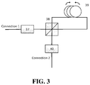
FIG. 3 is a composition block diagram of a sensing ring interferometer structure. - In the figures, broadband spectrum light source 1, 50:50 coupler 2, first wavelength division multiplexer 3, second wavelength division multiplexer 4, low speed photoelectric converter 5, interferometer controller 6, cavity length compensation adjuster 7, first optical amplifier 9, first photoelectric intensity modulator 10, first optical circulator 11, first optical coupler 12, narrowband bidirectional optical filter 13, first stage cavity-length adjuster 14, second stage cavity-length adjuster 15, second optical coupler 16, second optical amplifier 17, second photoelectric intensity modulator 18, second optical circulator 19, first regenerative cavity cavity-length adjuster 20, first high speed photoelectric detector 21, first microwave filtering and amplifying unit 22, first microwave power divider 24, second regenerative cavity cavity-length adjuster 25, second high speed photoelectric detector 26, second microwave filtering and amplifying unit 27, sensing ring interferometer structure 29, cavity length control unit 30, first orthogonal polarization state adjustment unit 37, polarization beam splitter 38, fiber sensing ring 39, second orthogonal polarization state adjustment unit 40, external clock reference source 45, second microwave power divider 46, third microwave power divider 47 and difference frequency detection unit 48; the solid line parts in the figures represent light path connections, which are light paths; the dotted lines indicate microwave circuit connections, which are electrical paths.
- The present disclosure will now be described in further detail with reference to the accompanying drawings and specific examples.
- As shown in
FIG. 1 , a bidirectional microwave-over-fiber resonant system based on a circulator structure is provided according to an embodiment. The bidirectional microwave-over-fiber resonant system includes a broadband spectrumlight source 1, a 50:50coupler 2, a firstwavelength division multiplexer 3, a secondwavelength division multiplexer 4, a low speedphotoelectric converter 5, aninterferometer controller 6, a cavitylength compensation adjuster 7, a firstoptical amplifier 9, a firstphotoelectric intensity modulator 10, a firstoptical circulator 11, a firstoptical coupler 12, a narrowband bidirectionaloptical filter 13, a secondoptical coupler 16, a secondoptical amplifier 17, a secondphotoelectric intensity modulator 18, a secondoptical circulator 19, a first regenerative cavity cavity-length adjuster 20, a first high speedphotoelectric detector 21, a first microwave filtering and amplifyingunit 22, a firstmicrowave power divider 24, a second regenerative cavity cavity-length adjuster 25, a second high speedphotoelectric detector 26, a second microwave filtering and amplifyingunit 27, a sensingring interferometer structure 29, a secondmicrowave power divider 46, a thirdmicrowave power divider 47, and a differencefrequency detection unit 48. - The first
optical amplifier 9, the firstphotoelectric intensity modulator 10, the cavitylength compensation adjuster 7, the firstoptical circulator 11, the secondwavelength division multiplexer 4, the firstoptical coupler 12, the narrowband bidirectionaloptical filter 13, the sensingring interferometer structure 29, the secondoptical coupler 16, the firstwavelength division multiplexer 3 and the secondoptical circulator 19 are connected in sequence to form a clockwise ring resonant cavity. Resonant light in a clockwise direction passes sequentially through the firstoptical coupler 12, the second regenerative cavity cavity-length adjuster 25, the second high speedphotoelectric detector 26, the second microwave filtering and amplifyingunit 27, and the thirdmicrowave power divider 47 to be fed back and modulated by the firstphotoelectric intensity modulator 10, so as to constitute a clockwise regenerative mode-locked structure. An electric signal generated by the clockwise regenerative mode-locked structure is input into the differencefrequency detection unit 48 through the thirdmicrowave power divider 47. As an optical path adjusting unit, the second regeneration cavity cavity-length adjuster 25 can adopt a fiber stretcher, an adjustable optical delay line or a spatial optical displacement stage. - The second
optical amplifier 17, the secondphotoelectric intensity modulator 18, the secondoptical circulator 19, the firstwavelength division multiplexer 3, the secondoptical coupler 16, the sensingring interferometer structure 29, the narrowband bidirectionaloptical filter 13, the firstoptical coupler 12, the secondwavelength division multiplexer 4 and the firstoptical circulator 11 are connected in sequence to form a counterclockwise ring resonant cavity. Resonant light in a counterclockwise direction passes sequentially through the secondoptical coupler 16, the first regenerative cavity cavity-length adjuster 20, the first high speedphotoelectric detector 21, the first microwave filtering and amplifyingunit 22, the firstmicrowave power divider 24, and the secondmicrowave power divider 46 to be fed back and modulated by the secondphotoelectric intensity modulator 18, so as to constitute a counterclockwise regenerative mode-locked structure. An electric signal generated by the counterclockwise regenerative mode-locked structure is input into the differencefrequency detection unit 48 via the secondmicrowave power divider 46. As an optical path adjusting unit, the first regeneration cavity cavity-length adjuster 20 can adopt a fiber stretcher, an adjustable optical delay line or a spatial optical displacement stage. - The broadband spectrum
light source 1, the 50:50coupler 2, the firstwavelength division multiplexer 3, the secondwavelength division multiplexer 4, the low speedphotoelectric converter 5, theinterferometer controller 6 and the cavitylength compensation adjuster 7 constitute a reciprocity error compensation broadband spectrum optical interferometer with double loops in clockwise and counterclockwise directions. The light emitted by the broadband spectrumlight source 1 is divided into two arms via the 50:50 coupler 2 A first arm passes in sequence through the secondwavelength division multiplexer 4, the firstoptical circulator 11, the secondoptical amplifier 17, the secondphotoelectric intensity modulator 18, the secondoptical circulator 19, the firstwavelength division multiplexer 3, the 50:50coupler 2 to enter the low speedphotoelectric converter 5. A second arm sequentially passes through the firstwavelength division multiplexer 3, a secondoptical circulator 19, a firstoptical amplifier 9, a firstphotoelectric intensity modulator 10, the cavitylength compensation adjuster 7, the firstoptical circulator 11, the secondwavelength division multiplexer 4, the 50:50coupler 2 to enter the low speedphotoelectric converter 5. A detection signal of the low speedphotoelectric converter 5 passes throughinterferometer controller 6 and is output to control the cavitylength compensation adjuster 7 to achieve the same optical path in both arms of the broadband spectrum optical interferometer and eliminate non-reciprocal errors caused by non-bidirectional devices on both arms. The light emitted by the broadband spectrumlight source 1 does not interfere with the resonant light in the clockwise and counterclockwise directions. As the arm length adjusting unit of the broadband spectrum interferometer, the cavitylength compensation adjuster 7 can adopt some device such as a fiber stretcher, an adjustable optical delay line or a spatial optical displacement stage. - The sensing
ring interferometer structure 29 includes a first orthogonal polarizationstate adjusting unit 37, apolarization beam splitter 38, afiber sensing ring 39 and a second orthogonal polarizationstate adjusting unit 40. - The resonant light in the clockwise direction passes through the first orthogonal polarization
state adjusting unit 37 to separate the double-peak spectral signal of the narrowband bidirectionaloptical filter 13 into two paths of optical signals with perpendicular polarization states. The central wavelengths of the two paths of optical signals are respectivelyλ1 and λ2. The two paths of signals of λ1 and λ2 separated by thepolarization beam splitter 38 enter the opticalfiber sensing ring 39 to sense the angular velocity, and are then combined through thepolarization beam splitter 38. The combined signal passes through the second orthogonal polarizationstate adjusting unit 40, to realize that the output signal of the sensingring interferometer structure 29 has a consistent polarization state with the input signal thereof. - The resonant light in the counterclockwise direction passes through the second orthogonal polarization
state adjusting unit 40 to separate the double-peak spectral signal of the narrowband bidirectionaloptical filter 13 into two paths of optical signals with perpendicular polarization states. The central wavelengths of the two paths of optical signals are respectivelyλ1 and λ2. The two paths of signals of λ1 and λ2 separated by thepolarization beam splitter 38 enter the opticalfiber sensing ring 39 to sense the angular velocity, and are then combined through thepolarization beam splitter 38. The combined signal passes through the first orthogonal polarizationstate adjusting unit 37, to realize that the output signal of the sensingring interferometer structure 29 has a consistent polarization state with the input signal. - In the bidirectional microwave-over-fiber resonant system based on the circulator structure, microwave signals generated by the clockwise regenerative mode-locked structure and the counterclockwise regenerative mode-locked structure are input into the difference
frequency detection unit 48 to detect an angular velocity. - The narrowband bidirectional
optical filter 13 changes a resonant microwave-over-fiber signal when the system is operated into a double-peaked spectral signal. Wavelengths corresponding to spectral peaks are λ1 and λ2 respectively. A frequency difference between λ1 and λ2 is a modulating signal ƒ m, so as to achieve bidirectional dual-frequency resonance. - In the sensing ring interferometer structure, each of the first orthogonal polarization
state adjusting unit 37 and the second orthogonal polarizationstate adjusting unit 40 includes several polarization beam splitters and several polarization state controllers. - In the sensing
ring interferometer structure 29, two path of optical signals with perpendicular polarization states are transmitted in opposite directions at different speeds of light in the sensing ring, thereby increasing a detection gain of Sagnac effect of the sensing ring. - The signal with a wavelength of λ1 transmitted in the counterclockwise direction into the sensing ring has the same transmission path as the signal with a wavelength of λ2 transmitted in the clockwise direction into the sensing ring, and polarization states thereof are perpendicular. The signal with a wavelength of λ2 transmitted in the counterclockwise direction into the sensing ring has the same transmission path as the signal with a wavelength of λ1 transmitted in the clockwise direction into the sensing ring, and polarization states thereof are perpendicular. In this way, the wavelengths and polarization states of working optical signals in the clockwise direction and the counterclockwise direction are separated.
- The optical path differences (phase differences) generated by the Sagnac effect in the clockwise and counterclockwise resonant cavities have opposite signs, resulting in that the optical path difference in clockwise and counterclockwise directions is twice the optical path difference caused by unidirectional Sagnac effect.
- The method for detecting the angular velocity by using the bidirectional microwave-over-fiber resonant system based on the circulator structure includes the following steps.
- Step 1: after the output light of the broadband spectrum
light source 1 with an isolator passes through the 50:50 coupler for power averaging, the light is split into two paths. The first path is injected into the firstwavelength division multiplexer 3, and then passes through the secondoptical circulator 19, the firstoptical amplifier 9, the firstphotoelectric intensity modulator 10, the cavitylength compensation adjuster 7 and the firstoptical circulator 11 sequentially in the clockwise direction, and finally output via the secondwavelength division multiplexer 4. The second path is injected into the secondwavelength division multiplexer 4, and then passes through the firstoptical circulator 11, the secondoptical amplifier 17, the secondphotoelectric intensity modulator 18 and the secondoptical circulator 19 in sequence in the counterclockwise direction, and finally output via the firstwavelength division multiplexer 3. The two output signals from the firstwavelength division multiplexer 3 and the secondwavelength division multiplexer 4 are coupled back through the same 50:50coupler 2. The interference superposed signal is subjected to photoelectric conversion through a low speedphotoelectric converter 5 and fed back through aninterferometer controller 6 to adjust the cavitylength compensation adjuster 7 to keep the two arms of the interferometer equal in length. - Step 2: the output light of the first
optical amplifier 9 enters a common cavity in clockwise direction through the firstphotoelectric intensity modulator 10 and the firstoptical circulator 11. The light passes through the secondwavelength division multiplexer 4 in the common cavity and is split into two paths by the firstoptical coupler 12. One path of signal further passes through the narrowband bidirectionaloptical filter 13, the sensingring interferometer structure 29, the secondoptical coupler 16, the firstwavelength division multiplexer 3 and the secondoptical circulator 19 and then enters the firstoptical amplifier 9 again to form an optical resonant cavity. The other path of signal passes through the second regenerative cavity cavity-length adjuster 25, is subjected to photoelectric conversion by the second high speedphotoelectric detector 26, then enters into the second microwave filtering and amplifyingunit 27 for microwave filtering and amplification, and split into two paths through the thirdmicrowave power divider 47, one path of which is injected into the firstphotoelectric intensity modulator 10 for microwave modulation to form a regenerative mode-locked loop, and the other path of which is used as a resonant microwave output f1 in the clockwise direction. Adjusting the second regenerative cavity cavity-length adjuster 25 prior to the second high speedphotoelectric detector 26 can change the microwave phase injected into the firstphotoelectric intensity modulator 10 by the regenerative mode-locked loop to achieve a stable output at a frequency of f1. - Step 3: Regenerative mode-locked principle in the counterclockwise direction is similar to that in the clockwise direction. The output light of the second
optical amplifier 17 enters the common cavity in the counterclockwise direction through the secondphotoelectric intensity modulator 18 and the secondoptical circulator 19; and split into two paths by the secondoptical coupler 16 in the common cavity. One path of signal further passes through the sensingring interferometer structure 29, the narrowband bidirectionaloptical filter 13, the firstoptical coupler 12, the secondwavelength division multiplexer 4 and the firstoptical circulator 11 to enter the secondoptical amplifier 17 again to form an optical resonant cavity. The other path of signal passes through the first regenerative cavity cavity-length adjuster 20, is subjected to photoelectric conversion by the first high speedphotoelectric detector 21, then enters into the first microwave filtering and amplifyingunit 22 for microwave filtering and amplification, and split into two paths through the firstmicrowave power divider 24 and the secondmicrowave power divider 46; one path of which is injected into the secondphotoelectric intensity modulator 18 for microwave modulation to form a regenerative mode-locked loop, and the other path of which is used as the resonant microwave output f2 in the counterclockwise direction. Adjusting the first regenerative cavity cavity-length adjuster 20 prior to the first high speedphotoelectric detector 21 can change the microwave phase injected into the secondphotoelectric intensity modulator 18 by the regenerative mode-locked loop to achieve a stable output at a frequency of f2. - Step 4: the working light in the clockwise direction and the working light in the counterclockwise direction generate opposite Sagnac effects in the sensing
ring interferometer structure 29. The frequencydifference detection unit 48 detects a frequency difference, i.e., a beat frequency, between the frequency f1 and the frequency f2 obtained instep 1, which is recorded as Δƒ . - Step 5: the rotational angular velocity Ω r is obtained by the following formula:

where S is an area enclosed by the fiber sensing ring in the sensing ring interferometer structure, λ is a wavelength corresponding to the frequency f1 or the frequency f2, and L is a total fiber length of the fiber sensing ring; G 1 is a gain generated due to sensing to the Sagnac effect of two paths of signals with perpendicular polarization states after the working light in the clockwise direction enters the fiber sensing ring; G 2 is a gain generated due to sensing to the Sagnac effect of two paths of signals with perpendicular polarization states after the working light in the counterclockwise direction enters the fiber sensing ring. - As shown in
FIG. 2 , a bidirectional microwave-over-fiber resonant system based on a circulator structure is provided according to an embodiment. Based on the first embodiment, the bidirectional microwave-over-fiber resonant system further includes a cavity length control system. The cavity length control system includes a cavity length adjuster, a cavitylength control unit 30 and an externalclock reference source 45. - The cavity length adjuster is arranged in the bidirectional ring resonant cavity. The first
microwave power divider 24 is input into the cavitylength control unit 30; and the externalclock reference source 18 is input into the cavitylength control unit 30. The cavitylength control unit 30 is connected to the cavity length adjuster to stabilize the cavity length of the resonant cavity. - Further, the cavity length adjuster includes a first stage
cavity length adjuster 14 and a second stagecavity length adjuster 15. The first stagecavity length adjuster 14 has a larger adjustment range than the second stagecavity length adjuster 15. The first stagecavity length adjuster 14 is used for slow adjustment of the cavity length, and the second stagecavity length adjuster 15 is used for fast adjustment of the cavity length. The first stagecavity length adjuster 14 and the second stagecavity length adjuster 15 are used as an optical path adjustment unit, which may employ a fiber stretcher, a dimmable delay line, or a spatial light displacement stage. - Frequency discrimination and phase discrimination are performed on the microwave frequency f1 in the clockwise direction assigned by the second
microwave power divider 24 with the externalclock reference source 45. An output signal passes through the cavitylength control unit 30 to control a cavity length regulator for a cavity length locking of the clockwise resonant cavity. In this case, a resonant cavity length change in the clockwise direction is a sum of a resonant cavity length change in the clockwise direction before the cavity length locking and a resonant cavity length change in the counterclockwise direction before the cavity length locking. - Those skilled in the art will readily be able to make numerous variations and modifications from the written description, the drawings, and the claims provided herein without departing from the spirit and scope of the disclosure as defined in the claims. Any modifications and equivalent variations made to the above-described embodiments according to the technical idea and essence of the present disclosure fall within the scope of protection defined in the claims of the present disclosure.
Claims (10)
- A bidirectional microwave-over-fiber resonant system based on a circulator structure, comprising a broadband spectrum light source (1), a 50:50 coupler (2), a first wavelength division multiplexer (3), a second wavelength division multiplexer (4), a low speed photoelectric converter (5), an interferometer controller (6), a cavity length compensation adjuster (7), a first optical amplifier (9), a first photoelectric intensity modulator (10), a first optical circulator (11), a first optical coupler (12), a narrowband bidirectional optical filter (13), a second optical coupler (16), a second optical amplifier (17), a second photoelectric intensity modulator (18), a second optical circulator (19), a first regenerative cavity cavity-length adjuster (20), a first high speed photoelectric detector (21), a first microwave filtering and amplifying unit (22), a first microwave power divider (24), a second regenerative cavity cavity-length adjuster (25), a second high speed photoelectric detector (26), a second microwave filtering and amplifying unit (27), a sensing ring interferometer structure (29), a second microwave power divider (46), a third microwave power divider (47), and a difference frequency detection unit (48);wherein the first optical amplifier (9), the first photoelectric intensity modulator (10), the cavity length compensation adjuster (7), the first optical circulator (11), the second wavelength division multiplexer (4), the first optical coupler (12), the narrowband bidirectional optical filter (13), the sensing ring interferometer structure (29), the second optical coupler (16), the first wavelength division multiplexer (3) and the second optical circulator (19) are connected in sequence to form a clockwise ring resonant cavity; resonant light in a clockwise direction passes sequentially through the first optical coupler (12), the second regenerative cavity cavity-length adjuster (25), the second high speed photoelectric detector (26), the second microwave filtering and amplifying unit (27), and the third microwave power divider (47) to be fed back and modulated by the first photoelectric intensity modulator (10), so as to constitute a clockwise regenerative mode-locked structure; an electric signal generated by the clockwise regenerative mode-locked structure is input into the difference frequency detection unit (48) through the third microwave power divider (47);wherein the second optical amplifier (17), the second photoelectric intensity modulator (18), the second optical circulator (19), the first wavelength division multiplexer (3), the second optical coupler (16), the sensing ring interferometer structure (29), the narrowband bidirectional optical filter (13), the first optical coupler (12), the second wavelength division multiplexer (4) and the first optical circulator (11) are connected in sequence to form a counterclockwise ring resonant cavity; resonant light in a counterclockwise direction passes sequentially through the second optical coupler (16), the first regenerative cavity cavity-length adjuster (20), the first high speed photoelectric detector (21), the first microwave filtering and amplifying unit (22), the first microwave power divider (24), and the second microwave power divider (46) to be fed back and modulated by the second photoelectric intensity modulator (18), so as to constitute a counterclockwise regenerative mode-locked structure; an electric signal generated by the counterclockwise regenerative mode-locked structure is input into the difference frequency detection unit (48) via the second microwave power divider (46);wherein the broadband spectrum light source (1), the 50:50 coupler (2), the first wavelength division multiplexer (3), the second wavelength division multiplexer (4), the low speed photoelectric converter (5), the interferometer controller (6) and the cavity length compensation adjuster (7) constitute a reciprocity error compensation broadband spectrum optical interferometer with double loops in clockwise and counterclockwise directions; light emitted by the broadband spectrum light source (1) is divided into two arms via the 50:50 coupler (2), wherein a first arm passes in sequence through the second wavelength division multiplexer (4), the first optical circulator (11), the second optical amplifier (17), the second photoelectric intensity modulator (18), the second optical circulator (19), the first wavelength division multiplexer (3), the 50:50 coupler (2) to enter the low speed photoelectric converter (5); a second arm passes in sequence through the first wavelength division multiplexer (3), a second optical circulator (19), a first optical amplifier (9), a first photoelectric intensity modulator (10), the cavity length compensation adjuster (7), the first optical circulator (11), the second wavelength division multiplexer (4), the 50:50 coupler (2) to enter the low speed photoelectric converter (5); a detection signal of the low speed photoelectric converter (5) passes through the interferometer controller (6) and is output to control the cavity length compensation adjuster (7) to achieve a same optical path in both arms of the broadband spectrum optical interferometer and eliminate non-reciprocal errors caused by non-bidirectional devices on both arms; the light emitted by the broadband spectrum light source (1) does not interfere with the resonant light in the clockwise direction and the counterclockwise direction;the sensing ring interferometer structure (29) comprises a first orthogonal polarization state adjusting unit (37), a polarization beam splitter (38), a fiber sensing ring (39) and a second orthogonal polarization state adjusting unit (40);the resonant light in the clockwise direction passes through the first orthogonal polarization state adjustment unit (37) to adjust a double-peaked spectral signal of the narrowband bidirectional optical filter (13) to two paths of signals with perpendicular polarization states; and the two paths of signals enter the fiber sensing ring (39) via the polarization beam splitter (38), and pass through the polarization beam splitter (38) and the second orthogonal polarization state adjustment unit (40) to adjust the polarization states back to an initial state;the resonant light in the counterclockwise direction passes through the second orthogonal polarization state adjustment unit (40) to adjust the double-peaked spectral signal of the narrowband bidirectional optical filter (13) to two paths of signals with perpendicular polarization states; and the two paths of signals enter the fiber sensing ring (39) via the polarization beam splitter (38), and pass through the polarization beam splitter (38) and the first orthogonal polarization state adjustment unit (37) to adjust the polarization states back to an initial state.
- The bidirectional microwave-over-fiber resonant system based on the circulator structure according to claim 1, wherein microwave signals generated by the clockwise regenerative mode-locked structure and the counterclockwise regenerative mode-locked structure are input into the difference frequency detection unit (48) to detect an angular velocity.
- The bidirectional microwave-over-fiber resonant system based on the circulator structure according to claim 1, wherein the narrowband bidirectional optical filter (13) changes a resonant microwave-over-fiber signal when the system is operated into a double-peaked spectral signal to achieve bidirectional dual-frequency resonance; wavelengths corresponding to spectral peaks are λ1 and λ2 respectively, and a frequency difference between λ1 and λ2 is a modulating signal ƒ m.
- The bidirectional microwave-over-fiber resonant system based on the circulator structure according to claim 1, wherein in the sensing ring interferometer structure (29), each of the first orthogonal polarization state adjusting unit (37) and the second orthogonal polarization state adjusting unit (40) comprises a plurality of polarization beam splitters and a plurality of polarization state controllers.
- The bidirectional microwave-over-fiber resonant system based on the circulator structure according to claim 1, wherein in the sensing ring interferometer structure (29), two paths of signals with perpendicular polarization states are transmitted in opposite directions at different speeds of light in a sensing ring, to increase a detection gain of Sagnac effect of the sensing ring.
- The bidirectional microwave-over-fiber resonant system based on the circulator structure according to claim 1,wherein the first regenerative cavity cavity-length adjuster (20) and the second regenerative cavity cavity-length adjuster (25) act as an optical path adjusting unit; and each of the first regenerative cavity cavity-length adjuster (20) and the second regenerative cavity cavity-length adjuster (25) adopts a fiber stretcher, a dimmable delay line or a spatial light displacement stage; and the cavity length compensation adjuster (7) acts as a broadband spectrum interferometer arm length adjustment unit, and adopt a fiber stretcher, a dimmable light delay line or a spatial light displacement stage.
- The bidirectional microwave-over-fiber resonant system based on the circulator structure according to claim 1, further comprising a cavity length control system; wherein the cavity length control system comprises a cavity-length adjuster, a cavity length control unit (30) and an external clock reference source (45); the cavity-length adjuster is disposed within a bidirectional ring resonant cavity, the first microwave power divider (24) is input into the cavity length control unit (30), the external clock reference source (45) is input into the cavity length control unit (30), and the cavity length control unit (30) is connected to the cavity-length adjuster to stabilize a cavity length of the resonant cavity.
- The bidirectional microwave-over-fiber resonant system based on the circulator structure according to claim 1, wherein the cavity-length adjuster comprises a first stage cavity-length adjuster (14) and a second stage cavity-length adjuster (15); the first stage cavity-length adjuster (14) has a larger adjustment range than the second stage cavity-length adjuster (15); wherein the first stage cavity-length adjuster (14) is used for slow adjustment of cavity length, and the second stage cavity-length adjuster (15) is used for fast adjustment of cavity length; and the first stage cavity-length adjuster (14) and the second stage cavity-length adjuster (15) are used as an optical path adjustment unit, and each of the first stage cavity-length adjuster (14) and the second stage cavity-length adjuster (15) adopt a fiber stretcher, a dimmable light delay line or a spatial light displacement stage.
- A method for detecting an angular velocity by using the bidirectional microwave-over-fiber resonant system based on the circulator structure according to claim 1, comprising steps of:Step 1: working light in the clockwise direction passing through the clockwise ring resonant cavity and the clockwise regenerative mode-locked structure, so as to obtain a stable output at a frequency f1 by the third microwave power divider (47);working light in the counterclockwise direction passing through the counterclockwise ring resonant cavity and the counterclockwise regenerative mode-locked structure, so as to obtain a stable output at a frequency f2 by the second microwave power divider (46);Step 2: generating opposite Sagnac effects in the sensing ring interferometer structure (29) by the working light in the clockwise direction and the working light in the counterclockwise direction, and detecting a frequency difference between the frequency f1 and the frequency f2 obtained in step 1 as a beat frequency, by the frequency difference detection unit (48), wherein the frequency difference is recorded as Δƒ ;Step 3: obtaining a rotational angular velocity Ω r by a following formula:

- The method according to claim 9, wherein when the bidirectional microwave-over-fiber resonant system based on the circulator structure has a cavity length control system, frequency discrimination and phase discrimination are performed on the microwave frequency f1 in the counterclockwise direction assigned by the first microwave power divider (24) with an external clock reference source (45), and an output signal passes through a cavity length control unit (30) to control a cavity-length adjuster for counterclockwise resonant cavity length locking; and a cavity length change of the clockwise resonant cavity is a sum of a cavity length change of the clockwise resonant cavity before the cavity length locking and a cavity length change of the counterclockwise resonant cavity before the cavity length locking.
Applications Claiming Priority (1)
| Application Number | Priority Date | Filing Date | Title |
|---|---|---|---|
| PCT/CN2018/113213 WO2020087423A1 (en) | 2018-10-31 | 2018-10-31 | Bidirectional optical-carrying microwave resonance system based on circulator structure and method for detecting angular velocity by said system |
Publications (3)
| Publication Number | Publication Date |
|---|---|
| EP3875903A1 true EP3875903A1 (en) | 2021-09-08 |
| EP3875903A4 EP3875903A4 (en) | 2022-06-22 |
| EP3875903B1 EP3875903B1 (en) | 2023-09-13 |
Family
ID=70462924
Family Applications (1)
| Application Number | Title | Priority Date | Filing Date |
|---|---|---|---|
| EP18938457.1A Active EP3875903B1 (en) | 2018-10-31 | 2018-10-31 | Bidirectional optical-carrying microwave resonance system based on circulator structure and method for detecting angular velocity by said system |
Country Status (3)
| Country | Link |
|---|---|
| US (1) | US11874113B2 (en) |
| EP (1) | EP3875903B1 (en) |
| WO (1) | WO2020087423A1 (en) |
Families Citing this family (3)
| Publication number | Priority date | Publication date | Assignee | Title |
|---|---|---|---|---|
| EP3875904B1 (en) * | 2018-10-31 | 2023-05-24 | Zhejiang University | Polarization-maintaining fully-reciprocal bi-directional optical carrier microwave resonance system and angular velocity measurement method thereof |
| CN116026306B (en) * | 2023-03-30 | 2023-06-06 | 中国船舶集团有限公司第七〇七研究所 | Gyroscope based on low-coherence light source and angular velocity measurement method thereof |
| CN117128945B (en) * | 2023-10-20 | 2023-12-26 | 中北大学 | Super-sensitive angular velocity sensor based on singular surface and measuring method |
Family Cites Families (7)
| Publication number | Priority date | Publication date | Assignee | Title |
|---|---|---|---|---|
| JP3443534B2 (en) * | 1998-12-17 | 2003-09-02 | 日本電信電話株式会社 | Atomic frequency standard laser pulse oscillator |
| CN103267522B (en) * | 2013-05-10 | 2015-08-12 | 浙江大学 | The two-way frequency locking switching method of microwave gyroscope irreplaceable error is carried for eliminating light |
| CN103278150B (en) * | 2013-05-10 | 2015-10-28 | 浙江大学 | A kind of light of detection angle speed carries microwave gyroscope method |
| CN103471579B (en) * | 2013-09-29 | 2016-02-17 | 浙江大学 | A kind of angular velocity detection method adopting two-way full reciprocity coupling light electrical oscillator |
| CN104075705A (en) * | 2014-06-26 | 2014-10-01 | 中航捷锐(北京)光电技术有限公司 | Optical fiber gyroscope for improving velocity sensitivity |
| CN108344408B (en) * | 2017-12-19 | 2020-08-25 | 北京交通大学 | Angular velocity measuring device based on tunable optoelectronic oscillator |
| CN108614126B (en) * | 2018-05-30 | 2019-10-18 | 北京交通大学 | Angular velocity measurement device and method based on wideband adjustable optical-electronic oscillator |
-
2018
- 2018-10-31 EP EP18938457.1A patent/EP3875903B1/en active Active
- 2018-10-31 WO PCT/CN2018/113213 patent/WO2020087423A1/en unknown
-
2021
- 2021-04-30 US US17/244,965 patent/US11874113B2/en active Active
Also Published As
| Publication number | Publication date |
|---|---|
| WO2020087423A1 (en) | 2020-05-07 |
| US20220034660A1 (en) | 2022-02-03 |
| EP3875903A4 (en) | 2022-06-22 |
| EP3875903B1 (en) | 2023-09-13 |
| US11874113B2 (en) | 2024-01-16 |
Similar Documents
| Publication | Publication Date | Title |
|---|---|---|
| US11874113B2 (en) | Bidirectional optical-carrying microwave resonance system based on circulator structure and method for detecting angular velocity by said system | |
| US4702600A (en) | Method and apparatus for measuring angular rate with a passive optical resonator | |
| US9568319B2 (en) | Angular velocity detection method adopting bi-directional full reciprocal coupling optoelectronic oscillator | |
| CN109357672B (en) | Two-way optical carrier microwave resonance system based on circulator structure and method for detecting angular velocity of two-way optical carrier microwave resonance system | |
| JP6404656B2 (en) | Method and apparatus for tracking / rocking the free spectral range of a resonator and its application to a resonator fiber optic gyroscope | |
| CN103278150B (en) | A kind of light of detection angle speed carries microwave gyroscope method | |
| WO2011119232A2 (en) | Optical gyroscope sensors based on optical whispering gallery mode resonators | |
| JPH0130317B2 (en) | ||
| CN102692314A (en) | Apparatus and method for testing power spectral density of frequency noise of laser based on fiber resonator | |
| US11378401B2 (en) | Polarization-maintaining fully-reciprocal bi-directional optical carrier microwave resonance system and angular velocity measurement method thereof | |
| CN104950311A (en) | OEO (optoelectronic oscillator) based wide-range and high-precision absolute distance measurement system with self-calibration function | |
| CN110530497A (en) | Interference-type optical fiber vibrating sensing demodulating system and method based on optical-electronic oscillator | |
| CN115112111A (en) | Single-beam wide-spectrum light source secondary filtering resonant fiber optic gyroscope and closed-loop control method | |
| CN103267522B (en) | The two-way frequency locking switching method of microwave gyroscope irreplaceable error is carried for eliminating light | |
| CN114899702A (en) | Laser device offset frequency stabilizing device and method based on optical fiber ring resonator | |
| CN112113556B (en) | High-sensitivity resonant micro-optical gyroscope based on self-injection frequency locking and detection method thereof | |
| CN103267521A (en) | Method for detecting angular velocity through adopting one-loop two-way bidirectional resonant optical microwaves | |
| CN109323690B (en) | Polarization-preserving full-reciprocity bidirectional optical carrier microwave resonance system and angular velocity detection method thereof | |
| Li et al. | IFOG Based on Rhombic Optical Path Difference Bias Configuration for High-Frequency Angular Vibration Measurement | |
| Ye et al. | High-sensitivity angular velocity measurement based on bidirectional coupled optoelectronic oscillator | |
| US5285257A (en) | Optic rotation sensing apparatus and related method including providing synchronous detection at a phase at which the AM noise is minimized | |
| CN112129229A (en) | Quasi-distributed displacement measuring device and method based on photoelectric oscillator | |
| CN111060896A (en) | Large-range and high-precision absolute distance measuring instrument based on OEO (optical output interface) quick switching | |
| CN220649542U (en) | Integrated optical chip and optical gyroscope | |
| JPS63138208A (en) | Optical fiber gyro by phase modulation system |
Legal Events
| Date | Code | Title | Description |
|---|---|---|---|
| STAA | Information on the status of an ep patent application or granted ep patent |
Free format text: STATUS: THE INTERNATIONAL PUBLICATION HAS BEEN MADE |
|
| PUAI | Public reference made under article 153(3) epc to a published international application that has entered the european phase |
Free format text: ORIGINAL CODE: 0009012 |
|
| STAA | Information on the status of an ep patent application or granted ep patent |
Free format text: STATUS: REQUEST FOR EXAMINATION WAS MADE |
|
| 17P | Request for examination filed |
Effective date: 20210528 |
|
| AK | Designated contracting states |
Kind code of ref document: A1 Designated state(s): AL AT BE BG CH CY CZ DE DK EE ES FI FR GB GR HR HU IE IS IT LI LT LU LV MC MK MT NL NO PL PT RO RS SE SI SK SM TR |
|
| DAV | Request for validation of the european patent (deleted) | ||
| DAX | Request for extension of the european patent (deleted) | ||
| REG | Reference to a national code |
Ref legal event code: R079 Ref document number: 602018057765 Country of ref document: DE Free format text: PREVIOUS MAIN CLASS: G01C0019660000 Ipc: G01C0019720000 Ref country code: DE |
|
| A4 | Supplementary search report drawn up and despatched |
Effective date: 20220519 |
|
| RIC1 | Information provided on ipc code assigned before grant |
Ipc: G01C 19/72 20060101AFI20220513BHEP |
|
| GRAP | Despatch of communication of intention to grant a patent |
Free format text: ORIGINAL CODE: EPIDOSNIGR1 |
|
| STAA | Information on the status of an ep patent application or granted ep patent |
Free format text: STATUS: GRANT OF PATENT IS INTENDED |
|
| INTG | Intention to grant announced |
Effective date: 20230323 |
|
| GRAS | Grant fee paid |
Free format text: ORIGINAL CODE: EPIDOSNIGR3 |
|
| GRAA | (expected) grant |
Free format text: ORIGINAL CODE: 0009210 |
|
| STAA | Information on the status of an ep patent application or granted ep patent |
Free format text: STATUS: THE PATENT HAS BEEN GRANTED |
|
| AK | Designated contracting states |
Kind code of ref document: B1 Designated state(s): AL AT BE BG CH CY CZ DE DK EE ES FI FR GB GR HR HU IE IS IT LI LT LU LV MC MK MT NL NO PL PT RO RS SE SI SK SM TR |
|
| REG | Reference to a national code |
Ref country code: CH Ref legal event code: EP |
|
| REG | Reference to a national code |
Ref country code: DE Ref legal event code: R096 Ref document number: 602018057765 Country of ref document: DE |
|
| REG | Reference to a national code |
Ref country code: IE Ref legal event code: FG4D |
|
| P01 | Opt-out of the competence of the unified patent court (upc) registered |
Effective date: 20230908 |
|
| REG | Reference to a national code |
Ref country code: LT Ref legal event code: MG9D |
|
| REG | Reference to a national code |
Ref country code: NL Ref legal event code: MP Effective date: 20230913 |
|
| PG25 | Lapsed in a contracting state [announced via postgrant information from national office to epo] |
Ref country code: GR Free format text: LAPSE BECAUSE OF FAILURE TO SUBMIT A TRANSLATION OF THE DESCRIPTION OR TO PAY THE FEE WITHIN THE PRESCRIBED TIME-LIMIT Effective date: 20231214 |
|
| PG25 | Lapsed in a contracting state [announced via postgrant information from national office to epo] |
Ref country code: SE Free format text: LAPSE BECAUSE OF FAILURE TO SUBMIT A TRANSLATION OF THE DESCRIPTION OR TO PAY THE FEE WITHIN THE PRESCRIBED TIME-LIMIT Effective date: 20230913 Ref country code: RS Free format text: LAPSE BECAUSE OF FAILURE TO SUBMIT A TRANSLATION OF THE DESCRIPTION OR TO PAY THE FEE WITHIN THE PRESCRIBED TIME-LIMIT Effective date: 20230913 Ref country code: NO Free format text: LAPSE BECAUSE OF FAILURE TO SUBMIT A TRANSLATION OF THE DESCRIPTION OR TO PAY THE FEE WITHIN THE PRESCRIBED TIME-LIMIT Effective date: 20231213 Ref country code: LV Free format text: LAPSE BECAUSE OF FAILURE TO SUBMIT A TRANSLATION OF THE DESCRIPTION OR TO PAY THE FEE WITHIN THE PRESCRIBED TIME-LIMIT Effective date: 20230913 Ref country code: LT Free format text: LAPSE BECAUSE OF FAILURE TO SUBMIT A TRANSLATION OF THE DESCRIPTION OR TO PAY THE FEE WITHIN THE PRESCRIBED TIME-LIMIT Effective date: 20230913 Ref country code: HR Free format text: LAPSE BECAUSE OF FAILURE TO SUBMIT A TRANSLATION OF THE DESCRIPTION OR TO PAY THE FEE WITHIN THE PRESCRIBED TIME-LIMIT Effective date: 20230913 Ref country code: GR Free format text: LAPSE BECAUSE OF FAILURE TO SUBMIT A TRANSLATION OF THE DESCRIPTION OR TO PAY THE FEE WITHIN THE PRESCRIBED TIME-LIMIT Effective date: 20231214 Ref country code: FI Free format text: LAPSE BECAUSE OF FAILURE TO SUBMIT A TRANSLATION OF THE DESCRIPTION OR TO PAY THE FEE WITHIN THE PRESCRIBED TIME-LIMIT Effective date: 20230913 |
|
| PGFP | Annual fee paid to national office [announced via postgrant information from national office to epo] |
Ref country code: FR Payment date: 20231023 Year of fee payment: 6 |
|
| REG | Reference to a national code |
Ref country code: AT Ref legal event code: MK05 Ref document number: 1611699 Country of ref document: AT Kind code of ref document: T Effective date: 20230913 |
|
| PG25 | Lapsed in a contracting state [announced via postgrant information from national office to epo] |
Ref country code: NL Free format text: LAPSE BECAUSE OF FAILURE TO SUBMIT A TRANSLATION OF THE DESCRIPTION OR TO PAY THE FEE WITHIN THE PRESCRIBED TIME-LIMIT Effective date: 20230913 |
|
| PG25 | Lapsed in a contracting state [announced via postgrant information from national office to epo] |
Ref country code: IS Free format text: LAPSE BECAUSE OF FAILURE TO SUBMIT A TRANSLATION OF THE DESCRIPTION OR TO PAY THE FEE WITHIN THE PRESCRIBED TIME-LIMIT Effective date: 20240113 |