EP3875751B1 - Rotorblatt für eine windenergieanlage und rotorblattspitze - Google Patents
Rotorblatt für eine windenergieanlage und rotorblattspitze Download PDFInfo
- Publication number
- EP3875751B1 EP3875751B1 EP20160359.4A EP20160359A EP3875751B1 EP 3875751 B1 EP3875751 B1 EP 3875751B1 EP 20160359 A EP20160359 A EP 20160359A EP 3875751 B1 EP3875751 B1 EP 3875751B1
- Authority
- EP
- European Patent Office
- Prior art keywords
- rotor blade
- blade tip
- tip
- drainage hole
- bore
- Prior art date
- Legal status (The legal status is an assumption and is not a legal conclusion. Google has not performed a legal analysis and makes no representation as to the accuracy of the status listed.)
- Active
Links
Images


Classifications
-
- F—MECHANICAL ENGINEERING; LIGHTING; HEATING; WEAPONS; BLASTING
- F03—MACHINES OR ENGINES FOR LIQUIDS; WIND, SPRING, OR WEIGHT MOTORS; PRODUCING MECHANICAL POWER OR A REACTIVE PROPULSIVE THRUST, NOT OTHERWISE PROVIDED FOR
- F03D—WIND MOTORS
- F03D1/00—Wind motors with rotation axis substantially parallel to the air flow entering the rotor
- F03D1/06—Rotors
- F03D1/065—Rotors characterised by their construction elements
- F03D1/0675—Rotors characterised by their construction elements of the blades
-
- F—MECHANICAL ENGINEERING; LIGHTING; HEATING; WEAPONS; BLASTING
- F03—MACHINES OR ENGINES FOR LIQUIDS; WIND, SPRING, OR WEIGHT MOTORS; PRODUCING MECHANICAL POWER OR A REACTIVE PROPULSIVE THRUST, NOT OTHERWISE PROVIDED FOR
- F03D—WIND MOTORS
- F03D80/00—Details, components or accessories not provided for in groups F03D1/00 - F03D17/00
- F03D80/30—Lightning protection
-
- F—MECHANICAL ENGINEERING; LIGHTING; HEATING; WEAPONS; BLASTING
- F05—INDEXING SCHEMES RELATING TO ENGINES OR PUMPS IN VARIOUS SUBCLASSES OF CLASSES F01-F04
- F05B—INDEXING SCHEME RELATING TO WIND, SPRING, WEIGHT, INERTIA OR LIKE MOTORS, TO MACHINES OR ENGINES FOR LIQUIDS COVERED BY SUBCLASSES F03B, F03D AND F03G
- F05B2240/00—Components
- F05B2240/20—Rotors
- F05B2240/30—Characteristics of rotor blades, i.e. of any element transforming dynamic fluid energy to or from rotational energy and being attached to a rotor
-
- F—MECHANICAL ENGINEERING; LIGHTING; HEATING; WEAPONS; BLASTING
- F05—INDEXING SCHEMES RELATING TO ENGINES OR PUMPS IN VARIOUS SUBCLASSES OF CLASSES F01-F04
- F05B—INDEXING SCHEME RELATING TO WIND, SPRING, WEIGHT, INERTIA OR LIKE MOTORS, TO MACHINES OR ENGINES FOR LIQUIDS COVERED BY SUBCLASSES F03B, F03D AND F03G
- F05B2240/00—Components
- F05B2240/20—Rotors
- F05B2240/30—Characteristics of rotor blades, i.e. of any element transforming dynamic fluid energy to or from rotational energy and being attached to a rotor
- F05B2240/302—Segmented or sectional blades
-
- F—MECHANICAL ENGINEERING; LIGHTING; HEATING; WEAPONS; BLASTING
- F05—INDEXING SCHEMES RELATING TO ENGINES OR PUMPS IN VARIOUS SUBCLASSES OF CLASSES F01-F04
- F05B—INDEXING SCHEME RELATING TO WIND, SPRING, WEIGHT, INERTIA OR LIKE MOTORS, TO MACHINES OR ENGINES FOR LIQUIDS COVERED BY SUBCLASSES F03B, F03D AND F03G
- F05B2240/00—Components
- F05B2240/20—Rotors
- F05B2240/30—Characteristics of rotor blades, i.e. of any element transforming dynamic fluid energy to or from rotational energy and being attached to a rotor
- F05B2240/307—Blade tip, e.g. winglets
-
- F—MECHANICAL ENGINEERING; LIGHTING; HEATING; WEAPONS; BLASTING
- F05—INDEXING SCHEMES RELATING TO ENGINES OR PUMPS IN VARIOUS SUBCLASSES OF CLASSES F01-F04
- F05B—INDEXING SCHEME RELATING TO WIND, SPRING, WEIGHT, INERTIA OR LIKE MOTORS, TO MACHINES OR ENGINES FOR LIQUIDS COVERED BY SUBCLASSES F03B, F03D AND F03G
- F05B2260/00—Function
- F05B2260/60—Fluid transfer
- F05B2260/602—Drainage
-
- Y—GENERAL TAGGING OF NEW TECHNOLOGICAL DEVELOPMENTS; GENERAL TAGGING OF CROSS-SECTIONAL TECHNOLOGIES SPANNING OVER SEVERAL SECTIONS OF THE IPC; TECHNICAL SUBJECTS COVERED BY FORMER USPC CROSS-REFERENCE ART COLLECTIONS [XRACs] AND DIGESTS
- Y02—TECHNOLOGIES OR APPLICATIONS FOR MITIGATION OR ADAPTATION AGAINST CLIMATE CHANGE
- Y02E—REDUCTION OF GREENHOUSE GAS [GHG] EMISSIONS, RELATED TO ENERGY GENERATION, TRANSMISSION OR DISTRIBUTION
- Y02E10/00—Energy generation through renewable energy sources
- Y02E10/70—Wind energy
- Y02E10/72—Wind turbines with rotation axis in wind direction
Definitions
- the invention relates to a rotor blade for a wind turbine, which has a rotor blade main body and a rotor blade tip.
- the invention also relates to such a rotor blade tip.
- the rotor blades are made of fiber composite materials and are hollow inside. There are correspondingly large amounts of air within these cavities. The water bound in the air can condense on the inside of the rotor blades under certain conditions, such as temperature changes, etc., which leads to water accumulating in the rotor blade. This water must be able to drain out of the rotor blade to avoid subsequent damage.
- a drainage hole typically installed at an angle to the pitch axis.
- the hole extends through the laminate and/or through a metallic blade tip receptor to the end edge of the rotor blade.
- the rotor blade has only a small profile thickness in the area of the blade tip. This limits the diameter of the drainage hole, with the disadvantage that dirt, e.g. production residues, adhesive residues, can collect in the blade area in front of the hole, which clogs the relatively small hole so that water cannot drain away reliably.
- a negative pressure can form in the blade, which makes it difficult to open the access hatches at the blade root or even damages them.
- the US20110103963A1 relates to a method for producing a rotor blade for a wind turbine, which has a drainage hole in the region of the rotor blade tip, a rotor blade for a wind turbine with a drainage hole in the region of the rotor blade tip, a wind turbine with a corresponding rotor blade and the use of a surface element in a rotor blade for a wind turbine, which has a drainage hole in the region of the rotor blade tip.
- the US 2017/0335830 A1 relates to a lightning receptor for a rotor blade of a wind turbine, wherein the lightning receptor is manufactured in one piece in a casting process.
- An object underlying the invention is to provide a concept for a rotor blade which contributes to a particularly effective drainage of water from a rotor blade.
- a rotor blade for a wind turbine has a rotor blade main body which a rotor blade cavity.
- the rotor blade main body is formed, for example, by two half-shells made of fiber composite material that are firmly connected to one another along the nose edge and the trailing edge.
- the rotor blade has a rotor blade tip that is firmly connected to the rotor blade main body.
- the rotor blade main body and the rotor blade tip can be made in one piece, for example from a fiber composite material.
- the rotor blade main body can be made from a fiber composite material and the rotor blade tip from an electrically conductive material, for example metallic, and the rotor blade main body is firmly connected to the rotor blade tip by means of an adhesive connection.
- the rotor blade tip has a drainage hole that is fluidically coupled to the rotor blade cavity.
- the drainage hole is open to a suction-side surface of the rotor blade tip, so that fluid, in particular water, can be drained out of the rotor blade cavity on the suction-side surface of the rotor blade tip by means of the drainage hole.
- the bore center axis of the drainage bore is inclined with respect to the pitch axis in such a way that the bore center axis runs from the direction of a pressure-side surface in the direction of the suction-side surface of the rotor blade tip.
- the bore center axis of the drainage bore also runs at a certain angle with respect to the pitch axis of the rotor blade in the direction of a tip-side end of the rotor blade tip.
- a drainage bore in the sense of the invention is understood to mean both a straight bore and a channel produced by another manufacturing process, which can have a straight or slightly curved course.
- the drainage hole fluidically connects the rotor blade cavity with the suction-side surface of the rotor blade shell, so that condensed water from the rotor blade cavity can be drained outwards directly via the blade tip.
- An inlet opening of the drainage hole faces the rotor blade cavity, while an outlet opening of the drainage hole is arranged on the suction side (suction-side surface) of the rotor blade tip.
- the drainage hole is open on the one hand to the rotor blade cavity and on the other hand to the suction side.
- the drainage hole is, for example, a simple, single straight hole.
- the drainage hole described enables water to be drained particularly effectively and efficiently from the rotor blade.
- its positioning and its exit on the suction side enable air to be actively sucked out of the inside of the blade in the area of negative pressure during operation of the rotor blade.
- This contributes significantly to improved drainage of the rotor blade.
- the aerodynamic profile of the blade tip is not or only insignificantly negatively affected. It also helps to avoid cost disadvantages due to consequential damage caused by water entering the inside of the blade. It also makes it possible to make the hole with a larger diameter, as it extends through an area of the profile cross-section in which it has a sufficient thickness. Clogging of the hole can thus be reduced or even prevented. This allows cost savings to be achieved by avoiding service work (drilling).
- the rotor blade tip is preferably a separate component of the rotor blade.
- the rotor blade tip is designed to conduct electricity, for example.
- the rotor blade tip is made of aluminum, although multi-component structures made of metal, fiber material and non-conductive materials are also conceivable.
- the rotor blade tip is optionally designed as a lightning protection device, such as a so-called receptor.
- the rotor blade tip is typically connected to the suction and pressure side of the rotor blade during the manufacturing process of the rotor blade, in particular glued or laminated between the two blade shells.
- a bore center axis of the drainage bore is inclined with respect to the pitch axis in such a way that the bore center axis runs from the direction of a pressure-side surface in the direction of the suction-side surface of the rotor blade tip.
- the bore center axis runs inclined with respect to a main extension plane or center plane of the rotor blade tip. This also contributes to water being able to be drained away particularly effectively.
- a bore center axis of the drainage bore runs at a specific angle with respect to a pitch axis of the rotor blade in the direction of a tip-side end of the rotor blade tip.
- the pitch axis of the rotor blade is the axis about which the rotor blade can be rotated. This sets an angle of attack for the rotor blade during operation.
- the bore center axis and thus the drainage bore do not run parallel to the pitch axis.
- the drainage bore extends in the direction of the profile end edge, i.e. the bore center axis points in the direction of the profile end edge. The alignment of the bore center axis prevents vertical overflow of the drainage bore and thus aeroacoustic resonance. This also contributes to a cost advantage.
- the predetermined angle is, for example, in an interval of 1° to 45°, preferably 1° to 15°. This represents an optimum for the advantages and functions mentioned above.
- the drainage hole is designed in such a way that it is only accessible from the suction side.
- This has the advantage that the profile end edge of the rotor blade tip (trailing edge), unlike solutions known from the prior art, has a closed, continuous course.
- This enables a particularly effective aerodynamic profile at the rotor blade tip and makes a significant positive contribution to the aerodynamic properties of the rotor blade tip and thus of the rotor blade, with the acoustic properties in particular being optimized.
- the trailing edge of the blade tip can be made particularly thin. The A wind turbine with such a rotor blade can be operated in a particularly powerful mode.
- the drainage bore is freely accessible from the outside in a straight extension of its bore center axis. As above, this contributes to making maintenance work on the bore easy. In particular, a bore blocked by dirt can easily be drilled out again. The bore is therefore directly accessible from the outside for maintenance work.
- the suction-side surface of the rotor blade tip has a recess in the area of an outlet opening of the drainage hole. This in turn contributes to improved accessibility of the hole from the outside.
- the recess also helps to ensure particularly good aerodynamic and aeroacoustic properties of the rotor blade tip.
- the recess is, for example, a groove or trough made in the blade tip that extends as an extension of the hole.
- the drainage hole runs in an area of the blade with sufficient profile thickness and opens or flows into the recess on the suction side. In this area of the recess there is still a "residual profile thickness" so that the pressure side remains closed.
- the recess is designed in such a way that the drainage bore is freely accessible from the outside in a straight extension of its bore center axis, ie when the bore exits to the outside, the bore opens into a flat, plane surface.
- the depression is designed such that the suction-side surface has a substantially continuous contour in a direction perpendicular to the bore center axis.
- the depression is designed to be edge- and/or step-free along the bore center axis, for example rounded.
- the depression has no edges transverse to an air flow of the rotor blade during operation. This contributes in particular to an optimal flow pattern, with the aerodynamic and aeroacoustic properties being optimized.
- a diameter of the drainage bore is 1 mm to 20 mm, in particular it is 8 mm, 9 mm or 10 mm.
- the rotor blade tip is provided with a cover.
- the cover is placed in the area of the recess (cutout) and is permeable to water. On its outside, it has a contour adapted to the rotor blade surface, whereby the air flow on the outer contour can be optimized even further.
- a rotor blade tip for a rotor blade of a wind turbine is disclosed.
- the rotor blade tip is designed to be firmly connected to a rotor blade main body of the rotor blade.
- the rotor blade tip has a drainage bore that can be fluidically coupled to the rotor blade cavity and is open to a suction-side surface of the rotor blade tip. so that fluid can be drained out of the rotor blade cavity on the suction-side surface of the rotor blade tip by means of the drainage bore.
- a bore center axis of the drainage bore is inclined with respect to a pitch axis of the rotor blade such that the bore center axis runs from the direction of a pressure-side surface in the direction of the suction-side surface of the rotor blade tip.
- the bore center axis of the drainage bore runs at a certain angle with respect to the pitch axis of the rotor blade in the direction of a tip-side end of the rotor blade tip.
- the rotor blade tip enables the advantages and functions mentioned above.
- the further developments described above apply analogously to the rotor blade tip.
- FIG. 1 shows a schematic representation of a wind turbine 100.
- the wind turbine 100 has a tower 102.
- the tower 102 is supported by a foundation 104 attached to a base.
- a nacelle 106 is rotatably mounted at an end of the tower 102 opposite the base.
- the nacelle 106 has, for example, a generator which is coupled to a rotor 108 via a rotor shaft (not shown).
- the rotor 108 has one or more (wind turbine) rotor blades 110 which are arranged on a rotor hub 112.
- the rotor 108 is set in rotation by an air flow, for example wind. This rotational movement is transmitted to the generator via the rotor shaft and, if necessary, a gear.
- the generator converts the kinetic energy of the rotor 108 into electrical energy.
- FIG 2 shows a schematic of a rotor blade 110.
- the rotor blade 110 has the shape of a conventional rotor blade and is formed by a rotor blade main body 111 and a rotor blade tip 119.
- the rotor blade tip 119 is designed as a separate element and made of an aluminum material.
- the rotor blade tip 119 is firmly connected to the rotor blade main body 111 via an adhesive connection.
- the rotor blade main body 111 is formed by two interconnected half-shells made of fiber composite material and is essentially hollow on the inside, delimiting a rotor blade cavity 113.
- the rotor blade 110 has a rotor blade root region 114 that faces the rotor hub 112.
- the rotor blade root region 114 typically has an essentially circular cross-section.
- the rotor blade root region 114 is followed by a transition region 116 and a profile region 118 of the rotor blade 110.
- the rotor blade 110 has a pressure side 122 and an opposite suction side 124 with respect to a longitudinal extension direction 120.
- a rotor blade connection end 126 with a flange connection 128 is provided, by means of which the rotor blade 110 is mechanically connected to a pitch bearing or an extender.
- the rotor blade 110 i.e. both the rotor blade main body 111 and the rotor blade tip 119, has a profile end edge 140 and a profile nose edge 142.
- a profile depth 144 is defined as the distance from the profile end edge 140 to the profile nose edge 142 with respect to a profile cross-section.
- a profile thickness 146 is defined as a distance from the pressure side 122 to the suction side 124, which in the present context means the maximum profile thickness of a profile cross-section.
- the profile thickness 146 is measured at right angles to the longitudinal axis 120 and to the profile depth 144.
- a (profile) cross-section lies in a plane normal to the longitudinal axis 120.
- Figure 3 shows a perspective view looking at the suction side 124 of the rotor blade tip 119
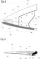
- Figure 4 shows a view along the rotor blade tip 119
- Figure 5 shows a plan view of the suction side 124 of the rotor blade tip 119.
- the rotor blade tip 119 is connected to the rotor blade main body 111 in such a way that there is an essentially seamless transition from the rotor blade main body 111 to the rotor blade tip 119 with regard to the aerodynamic profile (outer contour of the rotor blade), ie including the profile end and profile nose edge 140, 142.
- the rotor blade tip 119 has a suction-side surface 150 (of the suction side 124) and an opposite pressure-side surface 152 (of the pressure side 122).
- the rotor blade tip 119 has a drainage hole 154 which extends from the rotor blade cavity 113 (in Figures 3 and 4 indicated) extends towards the suction-side surface 150.
- An inlet opening 156 of the drainage bore 154 faces the rotor blade cavity 113, an outlet opening 158 of the drainage bore 154 is arranged on the suction side 124.
- the drainage bore 154 is only open towards the suction-side surface 150.
- the drainage bore 154 has a diameter 170 of 8 mm.
- the drainage bore 154 has a bore center axis 160 which extends from a pitch axis 164 at a predetermined, acute angle 162 which is in the range of approximately 1° to 10°.
- the bore center axis 160 lies in a main extension plane 166 in the direction of a tip-side end 165 of the rotor blade tip 119.
- the main extension plane 166 is, for example, a center plane of the blade tip 119, along which the blade tip has the greatest extension, for example compared to the significantly smaller extension in a thickness direction of the blade tip 119. It is essential that the bore center axis 160 does not coincide with the pitch axis 164, so that vertical overflow of the drainage bore 154 is prevented during operation.
- the drainage hole 154 runs at a distance from the profile trailing edge 140 and the profile leading edge 142 inside the rotor blade tip 119.
- the drainage bore 154 is slightly inclined with respect to the pitch axis 164, so that the bore center axis 160 runs from the direction of the pressure-side surface 152 in the direction of the suction-side surface 150 of the rotor blade tip 119. In other words, the drainage bore 154 runs in a Angle to the main extension plane 166 of the rotor blade tip 119.
- the suction-side surface 150 has a recess 168 in a straight extension of the bore center axis 160.
- the recess 168 directly adjoins the drainage bore 154 and is designed as a type of channel or trough.
- the recess 168 adjoins the outlet opening 158 of the drainage bore 154.
- the recess 168 is designed such that the drainage bore 154 is freely accessible from the outside in a straight extension of the bore center axis 160.
- the recess 168 is shaped such that in a straight extension of the bore center axis 160 its cross-section corresponds at least to the diameter 170 of the bore. In other words, the recess 168 represents a type of outlet of the drainage bore 154 into which the drainage bore 154 opens.
- the recess 168 is also designed so "harmoniously" that no edges or steps are provided, at least parallel to the bore center axis 160.
- the lines that delimit the recess 168 towards the suction-side surface 150 merely represent visible edges. Instead, the recess has a rounded, continuous contour. In other words, the recess is optimized in terms of aerodynamic properties, with jumps in the contour and sharp edges being avoided.
- the described drainage hole 154 is not open towards the pressure side 122, so that the pressure-side surface 152 is not penetrated by the drainage hole 154 and can form a closed surface.
- the drainage hole 154 is only accessible via the suction side 124.
- the Profile nose edge 142 and profile end edge 140 have a substantially closed, continuous course. In particular, these edges 140, 142 are not interrupted by the drainage hole 154.
- the described rotor blade tip 119 enables the advantages and functions mentioned above.
- a very effective and cost-effective drainage of fluid, in particular (condensation) water, from the rotor blade cavity 113 is made possible.
- Fluid which can collect in the rotor blade cavity 113 as described above is only drained outwards via the drainage hole 154 on the suction-side surface 150.
- Maintenance of the drainage hole 154 is very user-friendly and cost-effective, since the drainage hole 154 is very easily accessible and can be easily drilled out.
Landscapes
- Engineering & Computer Science (AREA)
- Life Sciences & Earth Sciences (AREA)
- Sustainable Development (AREA)
- Sustainable Energy (AREA)
- Chemical & Material Sciences (AREA)
- Combustion & Propulsion (AREA)
- Mechanical Engineering (AREA)
- General Engineering & Computer Science (AREA)
- Wind Motors (AREA)
Priority Applications (4)
| Application Number | Priority Date | Filing Date | Title |
|---|---|---|---|
| EP20160359.4A EP3875751B1 (de) | 2020-03-02 | 2020-03-02 | Rotorblatt für eine windenergieanlage und rotorblattspitze |
| ES20160359T ES2983511T3 (es) | 2020-03-02 | 2020-03-02 | Pala de rotor para una turbina de energía eólica y punta de pala de rotor |
| DK20160359.4T DK3875751T3 (da) | 2020-03-02 | 2020-03-02 | Rotorblad til et vindenergianlæg og rotorbladsspids |
| US17/183,015 US11549483B2 (en) | 2020-03-02 | 2021-02-23 | Rotor blade for a wind turbine and rotor blade tip |
Applications Claiming Priority (1)
| Application Number | Priority Date | Filing Date | Title |
|---|---|---|---|
| EP20160359.4A EP3875751B1 (de) | 2020-03-02 | 2020-03-02 | Rotorblatt für eine windenergieanlage und rotorblattspitze |
Publications (2)
| Publication Number | Publication Date |
|---|---|
| EP3875751A1 EP3875751A1 (de) | 2021-09-08 |
| EP3875751B1 true EP3875751B1 (de) | 2024-05-01 |
Family
ID=69743109
Family Applications (1)
| Application Number | Title | Priority Date | Filing Date |
|---|---|---|---|
| EP20160359.4A Active EP3875751B1 (de) | 2020-03-02 | 2020-03-02 | Rotorblatt für eine windenergieanlage und rotorblattspitze |
Country Status (4)
| Country | Link |
|---|---|
| US (1) | US11549483B2 (da) |
| EP (1) | EP3875751B1 (da) |
| DK (1) | DK3875751T3 (da) |
| ES (1) | ES2983511T3 (da) |
Family Cites Families (10)
| Publication number | Priority date | Publication date | Assignee | Title |
|---|---|---|---|---|
| DE102008048617B9 (de) | 2008-09-23 | 2012-08-16 | Repower Systems Ag | Rotorblatt für eine Windenergieanlage mit wenigstens einer Entwässerungsöffnung |
| EP2226497A1 (en) * | 2009-03-06 | 2010-09-08 | Lm Glasfiber A/S | Wind turbine blade with a lightning protection system |
| DE102009046293B4 (de) * | 2009-11-02 | 2013-03-28 | Repower Systems Ag | Rotorblatt mit Entwässerungsbohrung |
| DE102009046586B4 (de) * | 2009-11-10 | 2012-02-23 | Nordex Energy Gmbh | Blattspitze für ein Rotorblatt einer Windenergieanlage und Verfahren zur Montage der Blattspitze an ein Rotorblatt |
| DE102012015353A1 (de) | 2012-08-06 | 2014-02-06 | Carl Von Ossietzky Universität Oldenburg | Rotorblatt und Rotorblattspitze |
| US20150064003A1 (en) * | 2013-08-27 | 2015-03-05 | General Electric Company | Airflow modifying element for suppressing airflow noise |
| JP5941174B1 (ja) * | 2015-02-03 | 2016-06-29 | 株式会社日立製作所 | 風力発電装置 |
| DK3246562T3 (da) * | 2016-05-18 | 2019-05-13 | Nordex Energy Gmbh | Lynindfanger til et vindenergianlægs-rotorblad |
| DE102017107859A1 (de) | 2017-04-11 | 2018-10-11 | Nordex Energy Gmbh | Blitzschutzeinrichtung für ein Rotorblatt einer Windenergieanlage |
| EP3712422B1 (en) * | 2019-03-20 | 2023-10-11 | Siemens Gamesa Renewable Energy A/S | Rotor blade for a wind turbine |
-
2020
- 2020-03-02 DK DK20160359.4T patent/DK3875751T3/da active
- 2020-03-02 ES ES20160359T patent/ES2983511T3/es active Active
- 2020-03-02 EP EP20160359.4A patent/EP3875751B1/de active Active
-
2021
- 2021-02-23 US US17/183,015 patent/US11549483B2/en active Active
Also Published As
| Publication number | Publication date |
|---|---|
| DK3875751T3 (da) | 2024-08-05 |
| ES2983511T3 (es) | 2024-10-23 |
| US11549483B2 (en) | 2023-01-10 |
| EP3875751A1 (de) | 2021-09-08 |
| US20210270233A1 (en) | 2021-09-02 |
Similar Documents
| Publication | Publication Date | Title |
|---|---|---|
| EP2273101B1 (de) | Verfahren zur montage von rotorblättern einer windenergieanlage | |
| EP2325478B1 (de) | Rotorblatt mit Entwässerungsbohrung | |
| DE102009046586B4 (de) | Blattspitze für ein Rotorblatt einer Windenergieanlage und Verfahren zur Montage der Blattspitze an ein Rotorblatt | |
| EP2004990B1 (de) | Rotorblatt einer windenergieanlage | |
| EP1925818B1 (de) | Rotor einer Windenergieanlage mit einem Schott | |
| EP1923567A2 (de) | Rotorblatt und Windkraftanlage | |
| EP3855014B1 (de) | Geteiltes rotorblatt einer windenergieanlage sowie rotorblattsegment | |
| EP2582963B1 (de) | Peltonturbine mit einem wasserabfuhrsystem | |
| DE102013207640B4 (de) | Windenergieanlagen-Rotorblatt | |
| EP2366891A1 (de) | Windenergieanlagenrotorblatt | |
| WO2018211055A1 (de) | Windenergieanlagen-rotorblatt | |
| EP3455493B1 (de) | Windenergieanlagen-rotorblatt, und windenergieanlage mit selbigem | |
| WO2016045656A1 (de) | Windenergieanlagenrotorblatt | |
| WO2008003389A1 (de) | Rotornabe einer windenergieanlage | |
| DE102008048617B4 (de) | Rotorblatt für eine Windenergieanlage mit wenigstens einer Entwässerungsöffnung | |
| EP3875751B1 (de) | Rotorblatt für eine windenergieanlage und rotorblattspitze | |
| EP2758658B1 (de) | Schott einer windturbinenschaufel | |
| WO2011113764A2 (de) | Rotorblattentwässerung | |
| DE202007004136U1 (de) | Windkraftmaschine | |
| EP4577738B1 (de) | Rotorblatt für eine windenergieanlage sowie rotorblattspitze | |
| EP3280910A1 (de) | Windenergieanlagen-rotorblatt | |
| EP3954892A2 (de) | Rotorblatt für eine windenergieanlage, rotor für eine windenergieanlage, bauwerk und windenergieanlage | |
| EP3690231B1 (de) | Anbauelement für ein windenergieanlagenrotorblatt, anordnung sowie windenergieanlagenrotorblatt | |
| DE924619C (de) | Teilbare Leitschaufel | |
| EP3001028A1 (de) | Spinner für eine Rotornabe |
Legal Events
| Date | Code | Title | Description |
|---|---|---|---|
| PUAI | Public reference made under article 153(3) epc to a published international application that has entered the european phase |
Free format text: ORIGINAL CODE: 0009012 |
|
| STAA | Information on the status of an ep patent application or granted ep patent |
Free format text: STATUS: THE APPLICATION HAS BEEN PUBLISHED |
|
| AK | Designated contracting states |
Kind code of ref document: A1 Designated state(s): AL AT BE BG CH CY CZ DE DK EE ES FI FR GB GR HR HU IE IS IT LI LT LU LV MC MK MT NL NO PL PT RO RS SE SI SK SM TR |
|
| STAA | Information on the status of an ep patent application or granted ep patent |
Free format text: STATUS: REQUEST FOR EXAMINATION WAS MADE |
|
| 17P | Request for examination filed |
Effective date: 20220127 |
|
| RBV | Designated contracting states (corrected) |
Designated state(s): AL AT BE BG CH CY CZ DE DK EE ES FI FR GB GR HR HU IE IS IT LI LT LU LV MC MK MT NL NO PL PT RO RS SE SI SK SM TR |
|
| STAA | Information on the status of an ep patent application or granted ep patent |
Free format text: STATUS: EXAMINATION IS IN PROGRESS |
|
| 17Q | First examination report despatched |
Effective date: 20230622 |
|
| GRAP | Despatch of communication of intention to grant a patent |
Free format text: ORIGINAL CODE: EPIDOSNIGR1 |
|
| STAA | Information on the status of an ep patent application or granted ep patent |
Free format text: STATUS: GRANT OF PATENT IS INTENDED |
|
| INTG | Intention to grant announced |
Effective date: 20231120 |
|
| GRAS | Grant fee paid |
Free format text: ORIGINAL CODE: EPIDOSNIGR3 |
|
| GRAA | (expected) grant |
Free format text: ORIGINAL CODE: 0009210 |
|
| STAA | Information on the status of an ep patent application or granted ep patent |
Free format text: STATUS: THE PATENT HAS BEEN GRANTED |
|
| AK | Designated contracting states |
Kind code of ref document: B1 Designated state(s): AL AT BE BG CH CY CZ DE DK EE ES FI FR GB GR HR HU IE IS IT LI LT LU LV MC MK MT NL NO PL PT RO RS SE SI SK SM TR |
|
| REG | Reference to a national code |
Ref country code: GB Ref legal event code: FG4D Free format text: NOT ENGLISH |
|
| REG | Reference to a national code |
Ref country code: CH Ref legal event code: EP |
|
| REG | Reference to a national code |
Ref country code: IE Ref legal event code: FG4D Free format text: LANGUAGE OF EP DOCUMENT: GERMAN |
|
| REG | Reference to a national code |
Ref country code: DE Ref legal event code: R096 Ref document number: 502020007800 Country of ref document: DE |
|
| REG | Reference to a national code |
Ref country code: DK Ref legal event code: T3 Effective date: 20240731 |
|
| REG | Reference to a national code |
Ref country code: LT Ref legal event code: MG9D |
|
| REG | Reference to a national code |
Ref country code: NL Ref legal event code: MP Effective date: 20240501 |
|
| PG25 | Lapsed in a contracting state [announced via postgrant information from national office to epo] |
Ref country code: IS Free format text: LAPSE BECAUSE OF FAILURE TO SUBMIT A TRANSLATION OF THE DESCRIPTION OR TO PAY THE FEE WITHIN THE PRESCRIBED TIME-LIMIT Effective date: 20240901 |
|
| PG25 | Lapsed in a contracting state [announced via postgrant information from national office to epo] |
Ref country code: BG Free format text: LAPSE BECAUSE OF FAILURE TO SUBMIT A TRANSLATION OF THE DESCRIPTION OR TO PAY THE FEE WITHIN THE PRESCRIBED TIME-LIMIT Effective date: 20240501 |
|
| PG25 | Lapsed in a contracting state [announced via postgrant information from national office to epo] |
Ref country code: HR Free format text: LAPSE BECAUSE OF FAILURE TO SUBMIT A TRANSLATION OF THE DESCRIPTION OR TO PAY THE FEE WITHIN THE PRESCRIBED TIME-LIMIT Effective date: 20240501 Ref country code: FI Free format text: LAPSE BECAUSE OF FAILURE TO SUBMIT A TRANSLATION OF THE DESCRIPTION OR TO PAY THE FEE WITHIN THE PRESCRIBED TIME-LIMIT Effective date: 20240501 |
|
| PG25 | Lapsed in a contracting state [announced via postgrant information from national office to epo] |
Ref country code: GR Free format text: LAPSE BECAUSE OF FAILURE TO SUBMIT A TRANSLATION OF THE DESCRIPTION OR TO PAY THE FEE WITHIN THE PRESCRIBED TIME-LIMIT Effective date: 20240802 |
|
| PG25 | Lapsed in a contracting state [announced via postgrant information from national office to epo] |
Ref country code: PT Free format text: LAPSE BECAUSE OF FAILURE TO SUBMIT A TRANSLATION OF THE DESCRIPTION OR TO PAY THE FEE WITHIN THE PRESCRIBED TIME-LIMIT Effective date: 20240902 |
|
| PG25 | Lapsed in a contracting state [announced via postgrant information from national office to epo] |
Ref country code: NL Free format text: LAPSE BECAUSE OF FAILURE TO SUBMIT A TRANSLATION OF THE DESCRIPTION OR TO PAY THE FEE WITHIN THE PRESCRIBED TIME-LIMIT Effective date: 20240501 |
|
| REG | Reference to a national code |
Ref country code: ES Ref legal event code: FG2A Ref document number: 2983511 Country of ref document: ES Kind code of ref document: T3 Effective date: 20241023 |
|
| PG25 | Lapsed in a contracting state [announced via postgrant information from national office to epo] |
Ref country code: PL Free format text: LAPSE BECAUSE OF FAILURE TO SUBMIT A TRANSLATION OF THE DESCRIPTION OR TO PAY THE FEE WITHIN THE PRESCRIBED TIME-LIMIT Effective date: 20240501 |
|
| PG25 | Lapsed in a contracting state [announced via postgrant information from national office to epo] |
Ref country code: LV Free format text: LAPSE BECAUSE OF FAILURE TO SUBMIT A TRANSLATION OF THE DESCRIPTION OR TO PAY THE FEE WITHIN THE PRESCRIBED TIME-LIMIT Effective date: 20240501 |
|
| PG25 | Lapsed in a contracting state [announced via postgrant information from national office to epo] |
Ref country code: PT Free format text: LAPSE BECAUSE OF FAILURE TO SUBMIT A TRANSLATION OF THE DESCRIPTION OR TO PAY THE FEE WITHIN THE PRESCRIBED TIME-LIMIT Effective date: 20240902 Ref country code: PL Free format text: LAPSE BECAUSE OF FAILURE TO SUBMIT A TRANSLATION OF THE DESCRIPTION OR TO PAY THE FEE WITHIN THE PRESCRIBED TIME-LIMIT Effective date: 20240501 Ref country code: NO Free format text: LAPSE BECAUSE OF FAILURE TO SUBMIT A TRANSLATION OF THE DESCRIPTION OR TO PAY THE FEE WITHIN THE PRESCRIBED TIME-LIMIT Effective date: 20240801 Ref country code: NL Free format text: LAPSE BECAUSE OF FAILURE TO SUBMIT A TRANSLATION OF THE DESCRIPTION OR TO PAY THE FEE WITHIN THE PRESCRIBED TIME-LIMIT Effective date: 20240501 Ref country code: LV Free format text: LAPSE BECAUSE OF FAILURE TO SUBMIT A TRANSLATION OF THE DESCRIPTION OR TO PAY THE FEE WITHIN THE PRESCRIBED TIME-LIMIT Effective date: 20240501 Ref country code: IS Free format text: LAPSE BECAUSE OF FAILURE TO SUBMIT A TRANSLATION OF THE DESCRIPTION OR TO PAY THE FEE WITHIN THE PRESCRIBED TIME-LIMIT Effective date: 20240901 Ref country code: HR Free format text: LAPSE BECAUSE OF FAILURE TO SUBMIT A TRANSLATION OF THE DESCRIPTION OR TO PAY THE FEE WITHIN THE PRESCRIBED TIME-LIMIT Effective date: 20240501 Ref country code: GR Free format text: LAPSE BECAUSE OF FAILURE TO SUBMIT A TRANSLATION OF THE DESCRIPTION OR TO PAY THE FEE WITHIN THE PRESCRIBED TIME-LIMIT Effective date: 20240802 Ref country code: FI Free format text: LAPSE BECAUSE OF FAILURE TO SUBMIT A TRANSLATION OF THE DESCRIPTION OR TO PAY THE FEE WITHIN THE PRESCRIBED TIME-LIMIT Effective date: 20240501 Ref country code: BG Free format text: LAPSE BECAUSE OF FAILURE TO SUBMIT A TRANSLATION OF THE DESCRIPTION OR TO PAY THE FEE WITHIN THE PRESCRIBED TIME-LIMIT Effective date: 20240501 Ref country code: RS Free format text: LAPSE BECAUSE OF FAILURE TO SUBMIT A TRANSLATION OF THE DESCRIPTION OR TO PAY THE FEE WITHIN THE PRESCRIBED TIME-LIMIT Effective date: 20240801 |
|
| PG25 | Lapsed in a contracting state [announced via postgrant information from national office to epo] |
Ref country code: EE Free format text: LAPSE BECAUSE OF FAILURE TO SUBMIT A TRANSLATION OF THE DESCRIPTION OR TO PAY THE FEE WITHIN THE PRESCRIBED TIME-LIMIT Effective date: 20240501 |
|
| PG25 | Lapsed in a contracting state [announced via postgrant information from national office to epo] |
Ref country code: CZ Free format text: LAPSE BECAUSE OF FAILURE TO SUBMIT A TRANSLATION OF THE DESCRIPTION OR TO PAY THE FEE WITHIN THE PRESCRIBED TIME-LIMIT Effective date: 20240501 |
|
| PG25 | Lapsed in a contracting state [announced via postgrant information from national office to epo] |
Ref country code: SK Free format text: LAPSE BECAUSE OF FAILURE TO SUBMIT A TRANSLATION OF THE DESCRIPTION OR TO PAY THE FEE WITHIN THE PRESCRIBED TIME-LIMIT Effective date: 20240501 Ref country code: RO Free format text: LAPSE BECAUSE OF FAILURE TO SUBMIT A TRANSLATION OF THE DESCRIPTION OR TO PAY THE FEE WITHIN THE PRESCRIBED TIME-LIMIT Effective date: 20240501 |
|
| PG25 | Lapsed in a contracting state [announced via postgrant information from national office to epo] |
Ref country code: SM Free format text: LAPSE BECAUSE OF FAILURE TO SUBMIT A TRANSLATION OF THE DESCRIPTION OR TO PAY THE FEE WITHIN THE PRESCRIBED TIME-LIMIT Effective date: 20240501 |
|
| PG25 | Lapsed in a contracting state [announced via postgrant information from national office to epo] |
Ref country code: SM Free format text: LAPSE BECAUSE OF FAILURE TO SUBMIT A TRANSLATION OF THE DESCRIPTION OR TO PAY THE FEE WITHIN THE PRESCRIBED TIME-LIMIT Effective date: 20240501 Ref country code: SK Free format text: LAPSE BECAUSE OF FAILURE TO SUBMIT A TRANSLATION OF THE DESCRIPTION OR TO PAY THE FEE WITHIN THE PRESCRIBED TIME-LIMIT Effective date: 20240501 Ref country code: RO Free format text: LAPSE BECAUSE OF FAILURE TO SUBMIT A TRANSLATION OF THE DESCRIPTION OR TO PAY THE FEE WITHIN THE PRESCRIBED TIME-LIMIT Effective date: 20240501 Ref country code: EE Free format text: LAPSE BECAUSE OF FAILURE TO SUBMIT A TRANSLATION OF THE DESCRIPTION OR TO PAY THE FEE WITHIN THE PRESCRIBED TIME-LIMIT Effective date: 20240501 Ref country code: CZ Free format text: LAPSE BECAUSE OF FAILURE TO SUBMIT A TRANSLATION OF THE DESCRIPTION OR TO PAY THE FEE WITHIN THE PRESCRIBED TIME-LIMIT Effective date: 20240501 |
|
| REG | Reference to a national code |
Ref country code: DE Ref legal event code: R097 Ref document number: 502020007800 Country of ref document: DE |
|
| PG25 | Lapsed in a contracting state [announced via postgrant information from national office to epo] |
Ref country code: IT Free format text: LAPSE BECAUSE OF FAILURE TO SUBMIT A TRANSLATION OF THE DESCRIPTION OR TO PAY THE FEE WITHIN THE PRESCRIBED TIME-LIMIT Effective date: 20240501 |
|
| PLBE | No opposition filed within time limit |
Free format text: ORIGINAL CODE: 0009261 |
|
| STAA | Information on the status of an ep patent application or granted ep patent |
Free format text: STATUS: NO OPPOSITION FILED WITHIN TIME LIMIT |
|
| 26N | No opposition filed |
Effective date: 20250204 |
|
| PG25 | Lapsed in a contracting state [announced via postgrant information from national office to epo] |
Ref country code: SI Free format text: LAPSE BECAUSE OF FAILURE TO SUBMIT A TRANSLATION OF THE DESCRIPTION OR TO PAY THE FEE WITHIN THE PRESCRIBED TIME-LIMIT Effective date: 20240501 |
|
| PGFP | Annual fee paid to national office [announced via postgrant information from national office to epo] |
Ref country code: ES Payment date: 20250416 Year of fee payment: 6 |
|
| PG25 | Lapsed in a contracting state [announced via postgrant information from national office to epo] |
Ref country code: SE Free format text: LAPSE BECAUSE OF FAILURE TO SUBMIT A TRANSLATION OF THE DESCRIPTION OR TO PAY THE FEE WITHIN THE PRESCRIBED TIME-LIMIT Effective date: 20240501 |
|
| PG25 | Lapsed in a contracting state [announced via postgrant information from national office to epo] |
Ref country code: MC Free format text: LAPSE BECAUSE OF FAILURE TO SUBMIT A TRANSLATION OF THE DESCRIPTION OR TO PAY THE FEE WITHIN THE PRESCRIBED TIME-LIMIT Effective date: 20240501 |
|
| REG | Reference to a national code |
Ref country code: CH Ref legal event code: H13 Free format text: ST27 STATUS EVENT CODE: U-0-0-H10-H13 (AS PROVIDED BY THE NATIONAL OFFICE) Effective date: 20251023 |
|
| PG25 | Lapsed in a contracting state [announced via postgrant information from national office to epo] |
Ref country code: LU Free format text: LAPSE BECAUSE OF NON-PAYMENT OF DUE FEES Effective date: 20250302 |
|
| REG | Reference to a national code |
Ref country code: BE Ref legal event code: MM Effective date: 20250331 |
|
| PG25 | Lapsed in a contracting state [announced via postgrant information from national office to epo] |
Ref country code: BE Free format text: LAPSE BECAUSE OF NON-PAYMENT OF DUE FEES Effective date: 20250331 |
|
| PG25 | Lapsed in a contracting state [announced via postgrant information from national office to epo] |
Ref country code: CH Free format text: LAPSE BECAUSE OF NON-PAYMENT OF DUE FEES Effective date: 20250331 |
|
| PG25 | Lapsed in a contracting state [announced via postgrant information from national office to epo] |
Ref country code: IE Free format text: LAPSE BECAUSE OF NON-PAYMENT OF DUE FEES Effective date: 20250302 |
|
| PGFP | Annual fee paid to national office [announced via postgrant information from national office to epo] |
Ref country code: GB Payment date: 20260324 Year of fee payment: 7 |
|
| PGFP | Annual fee paid to national office [announced via postgrant information from national office to epo] |
Ref country code: DE Payment date: 20260320 Year of fee payment: 7 Ref country code: DK Payment date: 20260323 Year of fee payment: 7 |
|
| PGFP | Annual fee paid to national office [announced via postgrant information from national office to epo] |
Ref country code: FR Payment date: 20260325 Year of fee payment: 7 |