EP3875412A1 - Speicheranordnung - Google Patents
Speicheranordnung Download PDFInfo
- Publication number
- EP3875412A1 EP3875412A1 EP20160443.6A EP20160443A EP3875412A1 EP 3875412 A1 EP3875412 A1 EP 3875412A1 EP 20160443 A EP20160443 A EP 20160443A EP 3875412 A1 EP3875412 A1 EP 3875412A1
- Authority
- EP
- European Patent Office
- Prior art keywords
- storage assembly
- reel
- axle
- metal element
- cylindrical metal
- Prior art date
- Legal status (The legal status is an assumption and is not a legal conclusion. Google has not performed a legal analysis and makes no representation as to the accuracy of the status listed.)
- Withdrawn
Links
- 238000003860 storage Methods 0.000 title claims abstract description 68
- 229910052751 metal Inorganic materials 0.000 claims abstract description 61
- 239000002184 metal Substances 0.000 claims abstract description 60
- 239000000463 material Substances 0.000 claims abstract description 21
- 238000004804 winding Methods 0.000 claims abstract description 15
- 239000004033 plastic Substances 0.000 claims abstract description 10
- 229920003023 plastic Polymers 0.000 claims abstract description 10
- 150000002739 metals Chemical class 0.000 claims description 3
- 229920000642 polymer Polymers 0.000 claims description 3
- 238000005452 bending Methods 0.000 description 9
- 238000000034 method Methods 0.000 description 3
- 238000010146 3D printing Methods 0.000 description 2
- XEEYBQQBJWHFJM-UHFFFAOYSA-N Iron Chemical compound [Fe] XEEYBQQBJWHFJM-UHFFFAOYSA-N 0.000 description 2
- PXHVJJICTQNCMI-UHFFFAOYSA-N Nickel Chemical compound [Ni] PXHVJJICTQNCMI-UHFFFAOYSA-N 0.000 description 2
- 229910052782 aluminium Inorganic materials 0.000 description 2
- XAGFODPZIPBFFR-UHFFFAOYSA-N aluminium Chemical compound [Al] XAGFODPZIPBFFR-UHFFFAOYSA-N 0.000 description 2
- 238000004519 manufacturing process Methods 0.000 description 2
- RYGMFSIKBFXOCR-UHFFFAOYSA-N Copper Chemical compound [Cu] RYGMFSIKBFXOCR-UHFFFAOYSA-N 0.000 description 1
- 240000000491 Corchorus aestuans Species 0.000 description 1
- 235000011777 Corchorus aestuans Nutrition 0.000 description 1
- 235000010862 Corchorus capsularis Nutrition 0.000 description 1
- 229920000742 Cotton Polymers 0.000 description 1
- 244000043261 Hevea brasiliensis Species 0.000 description 1
- 239000004677 Nylon Substances 0.000 description 1
- 239000004698 Polyethylene Substances 0.000 description 1
- 229910000831 Steel Inorganic materials 0.000 description 1
- 239000000654 additive Substances 0.000 description 1
- 230000000996 additive effect Effects 0.000 description 1
- 230000000712 assembly Effects 0.000 description 1
- 238000000429 assembly Methods 0.000 description 1
- 238000005266 casting Methods 0.000 description 1
- 229910052802 copper Inorganic materials 0.000 description 1
- 239000010949 copper Substances 0.000 description 1
- 230000008878 coupling Effects 0.000 description 1
- 238000010168 coupling process Methods 0.000 description 1
- 238000005859 coupling reaction Methods 0.000 description 1
- 229920001971 elastomer Polymers 0.000 description 1
- 239000011152 fibreglass Substances 0.000 description 1
- 238000005242 forging Methods 0.000 description 1
- 238000009434 installation Methods 0.000 description 1
- 229910052742 iron Inorganic materials 0.000 description 1
- 238000000465 moulding Methods 0.000 description 1
- 229920003052 natural elastomer Polymers 0.000 description 1
- 229920001194 natural rubber Polymers 0.000 description 1
- 229910052759 nickel Inorganic materials 0.000 description 1
- 229920001778 nylon Polymers 0.000 description 1
- -1 polyethylene Polymers 0.000 description 1
- 229920000573 polyethylene Polymers 0.000 description 1
- 229920002635 polyurethane Polymers 0.000 description 1
- 239000004814 polyurethane Substances 0.000 description 1
- 229920000915 polyvinyl chloride Polymers 0.000 description 1
- 239000004800 polyvinyl chloride Substances 0.000 description 1
- 239000005060 rubber Substances 0.000 description 1
- 238000004528 spin coating Methods 0.000 description 1
- 238000009987 spinning Methods 0.000 description 1
- 229910001220 stainless steel Inorganic materials 0.000 description 1
- 239000010935 stainless steel Substances 0.000 description 1
- 239000010959 steel Substances 0.000 description 1
- 229920003051 synthetic elastomer Polymers 0.000 description 1
- 239000002023 wood Substances 0.000 description 1
Images
Classifications
-
- B—PERFORMING OPERATIONS; TRANSPORTING
- B65—CONVEYING; PACKING; STORING; HANDLING THIN OR FILAMENTARY MATERIAL
- B65H—HANDLING THIN OR FILAMENTARY MATERIAL, e.g. SHEETS, WEBS, CABLES
- B65H75/00—Storing webs, tapes, or filamentary material, e.g. on reels
- B65H75/02—Cores, formers, supports, or holders for coiled, wound, or folded material, e.g. reels, spindles, bobbins, cop tubes, cans, mandrels or chucks
- B65H75/34—Cores, formers, supports, or holders for coiled, wound, or folded material, e.g. reels, spindles, bobbins, cop tubes, cans, mandrels or chucks specially adapted or mounted for storing and repeatedly paying-out and re-storing lengths of material provided for particular purposes, e.g. anchored hoses, power cables
- B65H75/38—Cores, formers, supports, or holders for coiled, wound, or folded material, e.g. reels, spindles, bobbins, cop tubes, cans, mandrels or chucks specially adapted or mounted for storing and repeatedly paying-out and re-storing lengths of material provided for particular purposes, e.g. anchored hoses, power cables involving the use of a core or former internal to, and supporting, a stored package of material
- B65H75/44—Constructional details
- B65H75/4457—Arrangements of the frame or housing
-
- B—PERFORMING OPERATIONS; TRANSPORTING
- B65—CONVEYING; PACKING; STORING; HANDLING THIN OR FILAMENTARY MATERIAL
- B65H—HANDLING THIN OR FILAMENTARY MATERIAL, e.g. SHEETS, WEBS, CABLES
- B65H2701/00—Handled material; Storage means
- B65H2701/30—Handled filamentary material
- B65H2701/33—Hollow or hose-like material
Definitions
- the present disclosure relates to a storage assembly. More specifically, the present disclosure relates to the storage assembly with improvements allowing handling of higher loads.
- a storage assembly may be any housing which allows storage of a component.
- the component may be any material such as a hose, a rope, a thread and the like.
- the storage assembly may be a hose box.
- the hose box allows sitting of a reel to which a hose is wound.
- the reel may be provided with one or more bearings.
- the '268 reference provides a winding drum.
- the winding drum includes a hub member.
- the winding drum includes a plurality of wire spokes bent to U-shape and affixed by their cross-portions to the hub member in circumferentially spaced relation.
- the cross-portions are in substantially parallel relation to one another and arms of each U-shaped spoke extend substantially radially outward from the hub member. Rings are attached to the outer ends of the arms forming rims for the winding drum.
- the '268 reference falls short of disclosing any arrangement to reinforce and customize the hub member or other crucial parts of the winding drum.
- the storage assembly is for a flexible tubular component.
- the storage assembly includes an axle.
- the axle is configured with one or more axle stubs.
- the storage assembly includes a reel.
- the reel is rotatably mounted around the axle to allow winding of the tubular component on the reel.
- the reel is manufactured of a plastic material.
- the storage assembly is characterized in that the one or more axle stubs at least partially enclose at least one cylindrical metal element therein.
- the storage assembly is a hose box.
- the hose box allows ease of handling and storage of the hose.
- the tubular component is one or more of a hose, an electrical cable, an electric fence wire, a power flex, a rope etc.
- the flexible tubular component allows an effective winding on the reel.
- the storage assembly further includes one or more bearings at each end of the axle.
- the one or more bearings allow to retain the wound tubular component within the storage assembly.
- the cylindrical metal element is one or more of a tube, a rod, and a pipe. This provides desired strength to the reel as per the requirements of the user.
- the cylindrical metal element has a length which is longer than a total length of the one or more axle stubs. This helps to customize the total length of the one or more axle stubs enclosing the cylindrical metal element.
- the one or more axle stubs are connected to the cylindrical metal element. This provides a firm connection between the cylindrical metal element and the one or more axle stubs.
- the cylindrical metal element and the one or more axle stubs are connected by a snap connection.
- the snap connection helps to avoid inadvertent movement of the reel relative to the one or more axle stubs.
- the cylindrical metal element is locking and safeguarding the snap connection between the reel and the one or more axle stubs.
- the cylindrical metal element along with the snap connection prevents the reel from moving away from the one or more axle stubs.
- a material of the cylindrical metal element is having higher toughness than a material of the one or more axle stubs. The helps the cylindrical metal element in taking up some of the forces and reduces the bending moment being borne by the reel.
- the cylindrical metal element is fixed with the reel. This prevents bending of the reel even on winding of heavy tubular component.
- the cylindrical metal element is removably assembled with the reel. This allows a user to select suitable material of cylindrical metal element as per application requirements.
- the tubular component is made of a material selected from one or more of polymers, plastics, and metals. This provides the tubular component with characteristic features such as flexibility, cost efficiency, heat resistant properties, vibration resistant properties.
- the storage assembly is mounted on a wall surface. This makes the storage assembly widely usable in outdoor and indoor applications such as gardens, parks, buildings etc.
- the storage assembly is mounted on a ground surface. This also makes the storage assembly widely usable in outdoor and indoor applications such as gardens, parks, buildings.
- the one or more axle stubs are detachable from the reel. This allows to remove the cylindrical metal element as per the requirements.
- the one or more axle stubs are fixed to the reel.
- the fixed one or more axle stubs provides stability to the reel even on introducing heavy loads.
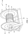
- FIG. 1 illustrates a storage assembly 100.
- the storage assembly 100 of the present disclosure may be any device which finds application in outdoor or garden installations to retain any object such as hose, rope and the like wound to a reel.
- the storage assembly 100 is a hose box.
- the hose box allows easy handling and storage of the hose.
- the storage assembly 100 may be mounted on a wall surface or on a ground surface. The mounting of the storage assembly 100 on a wall/ ground surface provides wide range of usage in outdoor and indoor applications such as gardens, parks, buildings.
- the storage assembly 100 is for a flexible tubular component 106 such as a hose, an electrical cable, an electric fence wire, a power flex, a rope and the like.
- the storage assembly 100 includes an axle 102.
- the storage assembly 100 further includes a reel 104.
- the reel 104 is rotatably mounted around the axle 102 to allow winding of the tubular component 106 on the reel 104.
- the reel 104 is used for storing, paying out and winding in of a wide variety of flexible tubular components 106.
- the reel 104 is manufactured of a plastic material.
- the axle 102 includes one or more bearings i.e. a first bearing 108 and a second bearing 110 one at each end of the axle 102.
- the first bearing 108 is towards a first housing side 112.
- the second bearing 110 is towards a second housing side 114.
- the first bearing 108 and the second bearing 110 are referred to as one or more bearings 108, 110 .
- the one or more bearings 108,110 allow to retain the wound tubular component 106 within the storage assembly 100 .
- the one or more bearings 108, 110 may be ball bearings, roller bearings, ball thrust bearings, roller thrust bearings, tapered roller thrust bearings and the like.
- the tubular component 106 such as hoses, electrical cables, electric fence wires, power flexes, ropes and the like may be made up of materials such as, need not necessarily nylon, polyurethane, polyethylene, poly vinyl chloride, synthetic or natural rubbers, cotton, manila, jute, metal.
- the tubular component 106 may be flexible, light weight, cost effective, heat-resistant, vibration-resistant. These properties provide an effective winding of the tubular component 106 around the reel 104.
- the reel 104 may be manufactured in multiple parts from a suitable plastic material and the multiple parts may then be assembled.
- the reel 104 may be located on a separate axle. Additionally, or alternatively, the reel 104 may be manufactured in a molded form from a plastic material and substantially in one piece. In the preferred form, the axle 102 is integrally molded into the reel 104.
- the reel 104 may even be manufactured from materials such as wood, fiberglass or metal like heavy-gauge steel, stainless steel, aluminum and the like.
- the reel 104 may be a spinning reel, a baitcasting reel, a spin casting reel, a surf fishing reel, a trolling reel, an offshore reel, a fly-fishing reel.
- the reel 104 may have a straight axle, a double drop axle, a full drop axle, or any other arrangement as known or used in the art.
- the reel 104 may be a stationary reel, a mobile reel, a reel cart, a hideaway, a spring-loaded reel, an air hose reel.
- the reel 104 may be chosen according to fitting properties of the reel 104 during housing of the reel 104 such that the reel 104 itself may allow to avoid bending.
- the one or more bearings 108, 110 may be difficult to assemble in a direct sitting at the storage assembly 100.
- the one or more bearings 108, 110 may be moved towards, or away from the storage assembly 100. These movements may cause a bending moment.
- a spring (not shown) may be provided to make the one or more bearings 108, 110 fit into the storage assembly 100. Further, the spring may allow benefits known in the relevant art such as ease of winding up of the reel 104.
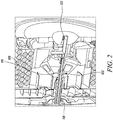
- FIG. 2 illustrates the axle 102 configured with one or more axle stubs i.e. a first axle stub 116 and a second axle stub 122.
- the first axle stub 116 and the second axle stub 122 are referred to as the one or more axle stubs 116, 122.
- the one or more axle stubs 116, 122 at least partially enclose at least one cylindrical metal element 118 within.
- the cylindrical metal element 118 helps in taking up some of the forces and reduces the bending moment being borne by the reel 104.
- the one or more axle stubs 116, 122 are connected to the cylindrical metal element 118.
- the cylindrical metal element 118 helps the reel 104 to bear high forces and retain its natural shape/arrangement.
- the cylindrical metal element 118 is one or more of a tube, a rod, and a pipe. This provides desired strength to the reel 104 as per the requirements of the user.
- the one or more axle stubs 116, 122 may be manufactured using any material, such as polymers, metals, plastics, and the like.
- the one or more axle stubs 116, 122 may be manufactured using any process, such as casting, molding, forging, fabrication, and the like.
- the one or more axle stubs 116, 122 may be manufactured by three-dimensional printing (also known as additive manufacturing or 3D printing).
- the one or more axle stubs 116, 122 may be one or more of an elliot axle stub, a reversed elliot axle stub, a lamoine axle stub, a reversed lamoine axle stub and the like.
- the one or more axle stubs 116, 122 may be integrally molded into the reel 104. Additionally, or alternatively, the one or more axle stubs 116, 122 may be manufactured separately. The one or more axle stubs 116, 122 may further be connected to the axle.
- the cylindrical metal element 118 may have a length which is longer than a total length of the one or more axle stubs 116, 122. This helps to customize the total length of the one or more axle stubs 116, 122 enclosing the cylindrical metal element 118. Further, a material of the cylindrical metal element 118 may have a higher toughness than a material of the one or more axle stubs 116, 122.
- the one or more axle stubs 116, 122 may be made up of a material such as plastic, rubber, and the cylindrical metal element 118 may be made up of copper, aluminum, nickel, iron or any other such material used or known in art. The cylindrical metal element 118 helps in taking up some of the forces and reduces the bending moment being borne by the reel 104.
- the cylindrical metal element 118 may be replaced by numerous smaller cylindrical metal elements. Length, thickness, width, and the like dimensions of the cylindrical metal element 118 may be adjustable. The strength of the cylindrical metal element 118 may be varied by changing these dimensions accordingly.
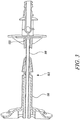
- FIG. 3 illustrates the one or more axle stubs 116, 122 of the storage assembly 100.
- the one or more axle stubs 116, 122 are connected to the reel 104 using a snap connection (not shown).
- the snap connection prevents the reel 104 from moving away from the one or more axle stubs 116, 122.
- the snap connection is positioned on the cylindrical metal element 118.
- the reel 104 locks the one or more axle stubs 116, 122 with the snap connection.
- the snap connection avoids swiveling even after any attachment or accessory (not shown) associated with the storage assembly 100 or the tubular component 106 is mounted.
- the cylindrical metal element 118 when inserted into the one or more axle stubs 116, 122 locks and safeguards the snap connection between the reel 104 and the one or more axle stubs 116, 122.
- the snap connection the reel 104 and the one or more axle stubs 116, 122 helps to avoid inadvertent movement of the reel 104 with the one or more axle stubs 116, 122.
- a single snap connection with desired features such as required size, shape, coupling quality and the like may be used individually. Or numerous small snap connections may be used to provide the required strength.
- the snap connection may be an annular snap fit, a cantilever snap fit, a torsional snap fit, a circle clip. Additionally, or alternatively, in some embodiments, the cylindrical metal element 118 itself and the one or more axle stubs 116, 122 are also connected by a further snap connection.
- cylindrical metal element 118 may be tied, glued to the one or more axle stubs 116, 122 or any such known method may be used. It is also possible that the cylindrical metal element 118 may be screwed to the one or more axle stubs 116, 122.
- the one or more axle stubs 116, 122 may be provided with sockets for receiving the cylindrical metal element 118.
- the one or more axle stubs 116, 122 may be provided with some clamping regions. These clamping regions further help to hold the cylindrical metal element 118 firmly.
- the one or more axle stubs 116, 122 may have a peculiar design to receive the cylindrical metal element 118. These features may prevent use of additional sources such as snap connections, circle clips and the like.
- the one or more axle stubs 116, 122 may be detachable from the reel 104. This allows to remove the cylindrical metal element 118 as per the requirements.
- the one or more axle stubs 116, 122 may be removed electromagnetically.
- a pry bar may be inserted between the one or more axle stubs 116, 122 and the cylindrical metal element 118 .
- the one or more axle stubs 116, 122 may be isolated by pulling the pry bar out.
- the axle stubs may be segregated by removing inserted circle clips (if provided).
- the one or more axle stubs 116, 122 may be fixed to the reel 104.
- the fixed one or more axle stubs 116, 122 provide stability to the reel 104 even on introducing heavy loads.
- the cylindrical metal element 118 may be fixed with the reel 104. This prevents bending of the reel 104 even on winding of heavy tubular component.
- the cylindrical metal element 118 may also be removably assembled with the reel 104. The removably assembled cylindrical metal element 118 may be substituted by any other desired cylindrical metal element 118 during service time of the storage assembly 100.
Landscapes
- Storage Of Web-Like Or Filamentary Materials (AREA)
Priority Applications (5)
| Application Number | Priority Date | Filing Date | Title |
|---|---|---|---|
| EP20160443.6A EP3875412A1 (de) | 2020-03-02 | 2020-03-02 | Speicheranordnung |
| CN202080097875.1A CN115210160B (zh) | 2020-03-02 | 2020-11-16 | 储存组件 |
| PCT/EP2020/082260 WO2021175467A1 (en) | 2020-03-02 | 2020-11-16 | Storage assembly |
| EP20803886.9A EP4114775B1 (de) | 2020-03-02 | 2020-11-16 | Speicheranordnung |
| TW110107239A TW202134162A (zh) | 2020-03-02 | 2021-03-02 | 儲存組件 |
Applications Claiming Priority (1)
| Application Number | Priority Date | Filing Date | Title |
|---|---|---|---|
| EP20160443.6A EP3875412A1 (de) | 2020-03-02 | 2020-03-02 | Speicheranordnung |
Publications (1)
| Publication Number | Publication Date |
|---|---|
| EP3875412A1 true EP3875412A1 (de) | 2021-09-08 |
Family
ID=69743161
Family Applications (2)
| Application Number | Title | Priority Date | Filing Date |
|---|---|---|---|
| EP20160443.6A Withdrawn EP3875412A1 (de) | 2020-03-02 | 2020-03-02 | Speicheranordnung |
| EP20803886.9A Active EP4114775B1 (de) | 2020-03-02 | 2020-11-16 | Speicheranordnung |
Family Applications After (1)
| Application Number | Title | Priority Date | Filing Date |
|---|---|---|---|
| EP20803886.9A Active EP4114775B1 (de) | 2020-03-02 | 2020-11-16 | Speicheranordnung |
Country Status (4)
| Country | Link |
|---|---|
| EP (2) | EP3875412A1 (de) |
| CN (1) | CN115210160B (de) |
| TW (1) | TW202134162A (de) |
| WO (1) | WO2021175467A1 (de) |
Citations (5)
| Publication number | Priority date | Publication date | Assignee | Title |
|---|---|---|---|---|
| US2523268A (en) | 1946-02-23 | 1950-09-26 | Atwood Vacuum Machine Co | Clothesline reel |
| DE7034022U (de) * | 1970-09-12 | 1971-01-07 | Brennenstuhl Hugo | Tragbare kabeltrommel. |
| GB2256632A (en) * | 1991-06-11 | 1992-12-16 | C Dax Systems Ltd | Moulded winding reel |
| US5782412A (en) * | 1995-07-28 | 1998-07-21 | Gulfstream Home & Garden, Inc. | Garden watering tool |
| US20130206891A1 (en) * | 2012-01-19 | 2013-08-15 | Jared Hendricks | Reel hanger clip |
Family Cites Families (2)
| Publication number | Priority date | Publication date | Assignee | Title |
|---|---|---|---|---|
| US5238201A (en) * | 1991-12-17 | 1993-08-24 | Jonushaitis Allen E | Hand-held line reel with brake |
| US20120255627A1 (en) * | 2011-04-08 | 2012-10-11 | Ames True Temper, Inc. | Hose reel assembly having limited hardware |
-
2020
- 2020-03-02 EP EP20160443.6A patent/EP3875412A1/de not_active Withdrawn
- 2020-11-16 WO PCT/EP2020/082260 patent/WO2021175467A1/en not_active Ceased
- 2020-11-16 CN CN202080097875.1A patent/CN115210160B/zh active Active
- 2020-11-16 EP EP20803886.9A patent/EP4114775B1/de active Active
-
2021
- 2021-03-02 TW TW110107239A patent/TW202134162A/zh unknown
Patent Citations (5)
| Publication number | Priority date | Publication date | Assignee | Title |
|---|---|---|---|---|
| US2523268A (en) | 1946-02-23 | 1950-09-26 | Atwood Vacuum Machine Co | Clothesline reel |
| DE7034022U (de) * | 1970-09-12 | 1971-01-07 | Brennenstuhl Hugo | Tragbare kabeltrommel. |
| GB2256632A (en) * | 1991-06-11 | 1992-12-16 | C Dax Systems Ltd | Moulded winding reel |
| US5782412A (en) * | 1995-07-28 | 1998-07-21 | Gulfstream Home & Garden, Inc. | Garden watering tool |
| US20130206891A1 (en) * | 2012-01-19 | 2013-08-15 | Jared Hendricks | Reel hanger clip |
Also Published As
| Publication number | Publication date |
|---|---|
| CN115210160A (zh) | 2022-10-18 |
| TW202134162A (zh) | 2021-09-16 |
| EP4114775A1 (de) | 2023-01-11 |
| WO2021175467A1 (en) | 2021-09-10 |
| CN115210160B (zh) | 2025-05-06 |
| EP4114775B1 (de) | 2024-02-28 |
Similar Documents
| Publication | Publication Date | Title |
|---|---|---|
| WO2008013800A2 (en) | Modular reel assembly | |
| US4667460A (en) | Electric lawn mower with self coiling power cord | |
| US11191259B1 (en) | Fishing spool tool | |
| US20100181406A1 (en) | Fly reel spool | |
| US9902589B2 (en) | Cord winder and rail storage system | |
| KR20070015218A (ko) | 호스, 케이블 등을 감거나 푸는 장치 | |
| US20060070965A1 (en) | Storage rack with tapered slots | |
| EP3875412A1 (de) | Speicheranordnung | |
| US20190118216A1 (en) | Paint roller frame and cage assembly and method of manufacturing | |
| US11291196B2 (en) | Outrigger kit for fishing | |
| US10618770B1 (en) | Electric fence wire reel apparatus | |
| JP2013062891A (ja) | 充電ケーブルの中間把持具 | |
| CN116692612A (zh) | 软管箱组件 | |
| US10526161B2 (en) | Wire spool guide | |
| US2755035A (en) | Combined hose reel and sprinkler | |
| US5709343A (en) | Adjustable drop nozzle system | |
| US8911337B2 (en) | Roller cover support assembly with roller cover retention spring | |
| US848239A (en) | Hose-reel. | |
| US20050072037A1 (en) | Fishing poles, counter-balancing apparatus for fishing poles and handles, and methods for balancing fishing poles | |
| US6463692B1 (en) | Angling device | |
| US7350737B2 (en) | Adjustable lead, cord, rope or sheet storage device | |
| US20170113898A1 (en) | Device for winding elongate flexible objects | |
| US20200299989A1 (en) | Turret cover stand | |
| JP3725110B2 (ja) | ケーブル吊り下げ用螺旋状ケーブルハンガーの架設方法 | |
| US20070108332A1 (en) | Helical Hose and Caddy Combination |
Legal Events
| Date | Code | Title | Description |
|---|---|---|---|
| PUAI | Public reference made under article 153(3) epc to a published international application that has entered the european phase |
Free format text: ORIGINAL CODE: 0009012 |
|
| STAA | Information on the status of an ep patent application or granted ep patent |
Free format text: STATUS: THE APPLICATION HAS BEEN PUBLISHED |
|
| AK | Designated contracting states |
Kind code of ref document: A1 Designated state(s): AL AT BE BG CH CY CZ DE DK EE ES FI FR GB GR HR HU IE IS IT LI LT LU LV MC MK MT NL NO PL PT RO RS SE SI SK SM TR |
|
| STAA | Information on the status of an ep patent application or granted ep patent |
Free format text: STATUS: THE APPLICATION IS DEEMED TO BE WITHDRAWN |
|
| 18D | Application deemed to be withdrawn |
Effective date: 20220310 |