EP3875336A1 - Ensemble d'évacuation pour véhicule ferroviaire - Google Patents
Ensemble d'évacuation pour véhicule ferroviaire Download PDFInfo
- Publication number
- EP3875336A1 EP3875336A1 EP21159974.1A EP21159974A EP3875336A1 EP 3875336 A1 EP3875336 A1 EP 3875336A1 EP 21159974 A EP21159974 A EP 21159974A EP 3875336 A1 EP3875336 A1 EP 3875336A1
- Authority
- EP
- European Patent Office
- Prior art keywords
- support
- evacuation
- tube
- state
- vehicle
- Prior art date
- Legal status (The legal status is an assumption and is not a legal conclusion. Google has not performed a legal analysis and makes no representation as to the accuracy of the status listed.)
- Granted
Links
Images

Classifications
-
- B—PERFORMING OPERATIONS; TRANSPORTING
- B61—RAILWAYS
- B61D—BODY DETAILS OR KINDS OF RAILWAY VEHICLES
- B61D19/00—Door arrangements specially adapted for rail vehicles
- B61D19/02—Door arrangements specially adapted for rail vehicles for carriages
- B61D19/023—Emergency exits
-
- B—PERFORMING OPERATIONS; TRANSPORTING
- B61—RAILWAYS
- B61D—BODY DETAILS OR KINDS OF RAILWAY VEHICLES
- B61D17/00—Construction details of vehicle bodies
- B61D17/04—Construction details of vehicle bodies with bodies of metal; with composite, e.g. metal and wood body structures
- B61D17/08—Sides
Definitions
- the present invention relates to an evacuation assembly for a railway vehicle.
- the invention also relates to an associated railway vehicle.
- Rail vehicles providing passenger transport are generally equipped with devices for emergency passenger evacuation.
- the purpose of such devices is to evacuate passengers in critical situations, in particular when the doors of the vehicle are no longer operational.
- an escape device widely used in railway vehicles comprises a window hammer and a metal ladder for use by passengers in an emergency situation.
- the glass breaker hammer is intended to be used to break a rail vehicle window.
- the metal ladder is intended to be hung on a wall of the vehicle before being launched outside the vehicle into the opening which has been made in the window.
- Such an evacuation device is particularly suitable for evacuating passengers from a multistage train.
- the evacuation device is configured to take two states: a first state, called rest, in which the support is in the first position and the tube is retracted into the support and a second state, called evacuation, in which the holder is in the second position and the tube is deployed out of the holder.
- the evacuation assembly also includes an actuator configured to change the evacuation device from the idle state to the evacuation state.
- the present description also relates to a railway vehicle comprising a side wall having at least one exterior opening and an evacuation assembly as described above.
- a double-decker rail vehicle 10 is shown in the figure 1 .
- the rail vehicle 10 comprises a locomotive 12 and two wagons 13.
- the number of wagons 13 is given by way of example.
- Each wagon 13 comprises a side wall 13A and at least one exterior opening 13B.
- the exterior opening 13B has dimensions adapted to allow the passage of an individual, in particular a passenger of the vehicle 10.
- each wagon 13 comprises an exterior opening 13B formed at the location of a window of the vehicle. The exterior opening 13B is nevertheless not closed by a window.
- each wagon 13 includes an evacuation assembly 15.
- each evacuation device 20 is arranged at an external opening 13B of the upper floor of the wagon 13, which allows the evacuation of the passengers located on the upper floor.
- the exhaust assembly 15 is also suitable for being disposed at an exterior opening 13B of the lower level of the vehicle 10.
- the exhaust assembly 15 is particularly advantageous in the case of the upper floor of the rail vehicle 10 since it is difficult for the passengers to get out of the vehicle 10 and in particular from a window without external assistance.
- the evacuation assembly 15 comprises an evacuation device 20 and an actuator 22.
- the evacuation device 20 is configured to take two states: a first state, called rest, in which the external opening 13B is closed and the evacuation of passengers from the vehicle 10 is not possible, and a second state, said evacuation, in which the external opening 13B is released and the evacuation of the passengers of the vehicle 10 is made possible.
- the evacuation device 20 comprises a support 24 and a tube 26.
- the evacuation device 20 also comprises an internal protection plate 28 and an external protection plate 30.
- the support 24 is intended to be fixed to the side wall 13A of the vehicle 10 so as to pivot between a first position in which the support 24 closes the external opening 13B and a second position in which the support 24 releases the external opening 13B to allow the passage of an individual.
- the dimensions of the support 24 depend on the dimensions of the exterior opening 13B of the vehicle 10.
- the length, respectively the width, of the support 24 is advantageously greater than or equal to the length, respectively the width, of the exterior opening. 13B, which allows the support 24 to close the outer opening 13B in the first position.
- the support 24 comprises an internal face 31A and an external face 31B opposite to the internal face 31A.
- the internal face 31A of the support 24 is intended to be positioned opposite the external opening 13B when the support 24 is in the first position.
- the support 24 is a parallelepipedal block, one of the edges of which is fixed to an edge of the outer opening 13B, for example, via a hinge.
- the support 24 is fixed to the lower edge of the outer opening 13B and is able to pivot around the lower edge.
- the support 24 in the first position, is substantially parallel to the side wall 13A, and is for example inserted into the exterior opening 13B. In the second position, the support 24 is substantially perpendicular to the side wall 13A so as to provide sufficient space to allow the evacuation of the passengers.
- the support 24 comprises a housing 32 for receiving the tube 26.
- the housing 32 is provided in the center of the support 24.
- the tube 26 has two ends. One of the ends of the tube 26 is fixed to the support 24, in particular at the level of the edges of the housing 32 of the support 24.
- the tube 26 is retractable in the support 24, in particular in the housing 32 of the support 24. Thus, when the tube 26 is retracted in the support 24, the end of the tube 26 not fixed to the support 24 is inserted into the support 24.
- retractable it is understood that the tube 26 is capable of being tucked inside the support 24.
- the support 24 In the resting state of the discharge device 20, the support 24 is in the first position and the tube 26 is retracted into the support 24. In the discharge state of the discharge device 20, the support 24 is. in the second position and the tube 26 is deployed out of the support 24. Thus, when the tube 26 is deployed out of the support 24, the tube 26 forms a “slide” allowing the passengers to slide out of the vehicle 10.
- the tube 26 has a length greater than or equal to 3 meters, for example, between 3 meters and 4 meters. This allows the evacuation of passengers located in a double-decker vehicle.
- the tube 26 is made of a flexible and elastic material.
- the tube 26 is made of elastomer.
- the tube 26 is formed of successive sections, at least one section having a smaller section than the other sections of the tube 26 so as to slow down the descent of an individual engaged in the tube 26.
- the sections preferably come from matter.
- the internal protective plate 28 is fixed to the support 24 via a pivot connection and is thus able to pivot relative to the support 24.
- the internal protection plate 28 is movable relative to the support 24 so that, in the rest state of the discharge device 20, the internal plate 28 is superimposed on the internal face 31A of the support 24 and in the In the evacuation state of the evacuation device 20, the internal plate 28 protrudes from the support 24 inside the vehicle 10.
- the internal plate 28 in the evacuation state of the evacuation device 20, forms an angle greater than or equal to 180 degrees with the support 24, preferably greater than or equal to 225 °. In the case where the internal plate 28 is substantially perpendicular to the support 24 in the evacuation state, the internal plate 28 then forms a step, which makes it possible to facilitate the access of the passengers of the vehicle 10 to the tube 26 in the support. 24.
- the internal plate 28 comprises at least one non-slip strip 33, in particular on the face of the internal plate 28 closest to the support 24 in the rest state of the discharge device 20.
- the non-slip strips 33 make it possible to reduce the risk of passengers slipping, which improves safety.
- the outer plate 30 is intended to be fixed to the side wall 13A of the vehicle 10 outside the vehicle 10 so as to be superimposed on the outer face 31B of the support 24 when the support 24 is in the first position.
- the outer plate 30 is movable relative to the side wall 13A, so that in the rest state of the discharge device 20, the outer plate 30 is superimposed on the outer face 31B of the support 24 and, in the state discharge, of the discharge device 20, the outer plate 30 forms an angle greater than or equal to 90 ° with the side wall 13A of the vehicle 10, advantageously is substantially perpendicular to the side wall 13A.
- the outer plate 30 thus makes it possible to protect the support 24 in the rest state of the evacuation device 20 while releasing the support 24 in the evacuation state of the evacuation device 20.
- the outer plate 30 comprises for example a side fixed to the side wall 13A at an edge of the outer opening 13B, for example, via a hinge.
- the outer plate 30 is fixed to the side wall at an upper edge of the outer opening 13B and is able to pivot around the upper edge.
- the actuator 22 is configured to change the evacuation device 20 from the idle state to the evacuation state.
- the actuator 22 is configured to be actuated by a passenger of the vehicle 10.
- the actuator 22 is, for example, a lever or a push button.
- FIG. 4 An example of the operation of the evacuation assembly 15 is illustrated by figure 4 .
- the evacuation device 20 is in a state of rest.
- a user of the rail vehicle 10 for example a passenger, actuates the actuator 22.
- the actuation of the actuator 22 triggers the passage of the evacuation device 20 from the rest state to the evacuation state.
- the outer protective plate 30 pivots so as to release the support 24.
- the support 24 pivots outwardly of the vehicle 10 from its first position to its second position.
- the internal protection plate 28 pivots towards the interior of the vehicle 10.
- the tube 26 is deployed out of the support 24 as visible on the figure. figure 4d .
- the evacuation of passengers from vehicle 10 is then possible.
- the evacuation assembly 15 is easy to use since the only action required for the passengers of the vehicle 10 is the actuation of the actuator 22, which allows the evacuation device 20 to pass automatically from the state of rest towards the state of evacuation. This also makes it possible to minimize the installation time of the evacuation device 20 and thus to make the evacuation faster.
- the safety of the passengers is increased since, compared with the state of the art, no window has to be broken since the opening 13B at which the evacuation device 20 is fixed does not have a window. In addition, the passengers do not intervene in the installation of the evacuation device 20 (except for the actuator 22).
- such an evacuation device 20 is compact and can be easily integrated into a rail vehicle 10.
- Such an evacuation assembly 15 is particularly suitable for a railway vehicle with two floors because the second floor is located very high above the ground, hence the interest of the tube 26 for evacuating the passengers.
- such an evacuation assembly 15 can also be used in a railway vehicle comprising a single stage.
Landscapes
- Engineering & Computer Science (AREA)
- Mechanical Engineering (AREA)
- Business, Economics & Management (AREA)
- Emergency Management (AREA)
- Life Sciences & Earth Sciences (AREA)
- Wood Science & Technology (AREA)
- Emergency Lowering Means (AREA)
Abstract
Description
- La présente invention concerne un ensemble d'évacuation pour véhicule ferroviaire. L'invention concerne également un véhicule ferroviaire associé.
- Les véhicules ferroviaires assurant le transport de passagers sont généralement dotés de dispositifs permettant l'évacuation d'urgence des passagers. De tels dispositifs ont pour visée d'évacuer les passagers dans des situations critiques, notamment lorsque les portes du véhicule ne sont plus opérationnelles.
- En particulier, un dispositif d'évacuation répandu dans les véhicules ferroviaires comprend un marteau brise-vitre et une échelle métallique destinés à être utilisés par les passagers en situation d'urgence. Le marteau brise-vitre est destiné à être utilisé pour briser une vitre du véhicule ferroviaire. L'échelle métallique est destinée à être accrochée à une paroi du véhicule avant d'être lancée à l'extérieur du véhicule dans l'ouverture qui a été ménagée dans la vitre. Un tel dispositif d'évacuation est particulièrement adapté pour évacuer des passagers d'un train à plusieurs étages.
- Néanmoins, un tel dispositif d'évacuation présente des risques pour la sécurité des passagers, notamment des risques de coupures dues aux bris du verre des vitres ou des risques de chutes dues à un mauvais positionnement de l'échelle. En outre, le temps de mise en place du dispositif d'évacuation, et donc de l'évacuation, est très dépendant de la dextérité et de la réactivité des passagers auxquels il est demandé de briser la vitre et de positionner correctement l'échelle métallique
- Il existe donc un besoin pour une solution permettant d'évacuer les passagers d'un véhicule de manière plus sécuritaire et plus rapide.
- A cet effet, la présente description a pour objet un ensemble d'évacuation pour véhicule ferroviaire comprenant une paroi latérale présentant au moins une ouverture extérieure. L'ensemble d'évacuation comprend :
- un dispositif d'évacuation comprenant :
- un support destiné à être fixé à la paroi latérale du véhicule de sorte à pivoter entre une première position dans laquelle le support obture l'ouverture extérieure et une deuxième position dans laquelle le support libère l'ouverture extérieure pour permettre le passage d'un individu,
- un tube dont l'une des extrémités est fixée au support, le tube étant rétractable dans le support,
- Le dispositif d'évacuation est configuré pour prendre deux états : un premier état, dit de repos, dans lequel le support est dans la première position et le tube est rétracté dans le support et un deuxième état, dit d'évacuation, dans lequel le support est dans la deuxième position et le tube est déployé hors du support.
- L'ensemble d'évacuation comprend également un actionneur configuré pour faire passer le dispositif d'évacuation de l'état de repos vers l'état d'évacuation.
- Suivant des modes de réalisations particuliers, l'ensemble d'évacuation comprend une ou plusieurs des caractéristiques suivantes, prises isolément ou suivant toutes les combinaisons techniquement possibles :
- Une face interne et une face externe est opposée à la face interne, la face interne du support étant destinée à être en regard de l'ouverture extérieure dans la première position du support, le dispositif d'évacuation comprenant une plaque interne de protection fixée au support, la plaque interne étant mobile par rapport au support de sorte que, dans l'état de repos du dispositif d'évacuation, la plaque interne est superposée à la face interne du support et dans l'état d'évacuation du dispositif d'évacuation, la plaque interne fait saillie par rapport au support à l'intérieur du véhicule.
- Dans l'état d'évacuation du dispositif d'évacuation, la plaque interne forme un angle supérieur ou égal à 180° avec le support.
- La plaque interne comprend au moins une bande antidérapante sur l'une de ses faces.
- Le support comprend une face interne et une face externe opposée à la face interne, la face interne du support étant destinée à être en regard de l'ouverture extérieure dans la première position du support, le dispositif d'évacuation comprenant une plaque externe de protection, la plaque externe étant destinée à être fixée de manière mobile à la paroi latérale du véhicule de sorte que, dans l'état de repos du dispositif d'évacuation, la plaque externe est superposée à la face externe du support et dans l'état d'évacuation du dispositif d'évacuation, la plaque externe forme un angle supérieur ou égal à 90° avec la paroi latérale du véhicule.
- Dans la deuxième position du support, le support est sensiblement perpendiculaire à la paroi latérale du véhicule.
- Le tube est en élastomère.
- Le tube est formé de tronçons successifs, au moins un tronçon présentant une section plus petite que les autres tronçons du tube de sorte à freiner la descente d'un individu engagé dans le tube.
- Le tube a une longueur supérieure ou égale à 3 mètres.
- La présente description porte aussi sur un véhicule ferroviaire comprenant une paroi latérale présentant au moins une ouverture extérieure et un ensemble d'évacuation tel que décrit précédemment.
- D'autres caractéristiques et avantages de l'invention apparaîtront à la lecture de la description qui suit de modes de réalisation de l'invention, donnée à titre d'exemple uniquement, et en référence aux figures suivantes :
- [
Fig 1 ] lafigure 1 est une représentation schématique d'un véhicule ferroviaire à double étage, - [
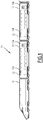
Fig 2 ] lafigure 2 est une représentation schématique d'un ensemble d'évacuation selon une première vue, - [
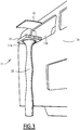
Fig 3 ] lafigure 3 est une représentation schématique de l'ensemble d'évacuation de lafigure 2 selon une deuxième vue, - [
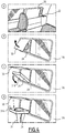
Fig 4 ] lafigure 4 est une représentation schématique du fonctionnement de l'ensemble d'évacuation illustré sur lesfigures 2 et3 . - Un véhicule ferroviaire 10 à double étages est représenté sur la
figure 1 . Dans cet exemple, le véhicule ferroviaire 10 comprend une locomotive 12 et deux wagons 13. Le nombre de wagons 13 est donné à titre d'exemple. - Chaque wagon 13 comprend une paroi latérale 13A et au moins une ouverture extérieure 13B. L'ouverture extérieure 13B présente des dimensions adaptées pour permettre le passage d'un individu, notamment d'un passager du véhicule 10. Dans l'exemple particulier illustré en
figure 1 , chaque wagon 13 comprend une ouverture extérieure 13B ménagée à l'emplacement d'une fenêtre du véhicule. L'ouverture extérieure 13B n'est néanmoins pas obturée par une vitre. - Dans l'exemple illustré par la
figure 1 , chaque wagon 13 comprend un ensemble d'évacuation 15. Dans l'exemple illustré sur lafigure 1 , chaque dispositif d'évacuation 20 est disposé au niveau d'une ouverture extérieure 13B de l'étage supérieure du wagon 13, ce qui permet l'évacuation des passagers situés à l'étage supérieur. - L'homme du métier comprendra que l'ensemble d'évacuation 15 est aussi adapté pour être disposé au niveau d'une ouverture extérieure 13B de l'étage inférieur du véhicule 10. Néanmoins, l'ensemble d'évacuation 15 est particulièrement avantageux dans le cas de l'étage supérieur du véhicule ferroviaire 10 puisqu'il est difficile pour les passagers de descendre du véhicule 10 et notamment d'une fenêtre sans aide extérieure.
- Un exemple d'ensemble d'évacuation 15 destiné à être positionné au niveau d'une ouverture extérieure 13B du véhicule 10, telle qu'une fenêtre (sans vitre), est illustré plus en détails sur les
figures 2 à 4 . - Dans l'exemple illustré sur les
figures 2 à 4 , l'ensemble d'évacuation 15 comprend un dispositif d'évacuation 20 et un actionneur 22. - Le dispositif d'évacuation 20 est configuré pour prendre deux états : un premier état, dit de repos, dans lequel l'ouverture extérieure 13B est obturée et l'évacuation de passagers du véhicule 10 n'est pas possible, et un deuxième état, dit d'évacuation, dans lequel l'ouverture extérieure 13B est libérée et l'évacuation des passagers du véhicule 10 est rendue possible.
- Le dispositif d'évacuation 20 comprend un support 24 et un tube 26. Optionnellement, le dispositif d'évacuation 20 comprend également une plaque interne de protection 28 et une plaque externe de protection 30.
- Le support 24 est destiné à être fixé à la paroi latérale 13A du véhicule 10 de sorte à pivoter entre une première position dans laquelle le support 24 obture l'ouverture extérieure 13B et une deuxième position dans laquelle le support 24 libère l'ouverture extérieure 13B pour permettre le passage d'un individu.
- Les dimensions du support 24 sont fonction des dimensions de l'ouverture extérieure 13B du véhicule 10. En particulier, la longueur, respectivement la largeur, du support 24 est avantageusement supérieure ou égale à la longueur, respectivement la largeur, de l'ouverture extérieure 13B, ce qui permet au support 24 d'obturer l'ouverture extérieure 13B dans la première position.
- Le support 24 comprend une face interne 31A et une face externe 31B opposée à la face interne 31A. La face interne 31A du support 24 est destinée à être positionnée en regard de l'ouverture extérieure 13B lorsque le support 24 est dans la première position.
- Dans l'exemple illustré sur les
figures 2 à 4 , le support 24 est un bloc parallélépipédique dont l'un des bords est fixé à un bord de l'ouverture extérieure 13B, par exemple, via une charnière. Dans cet exemple, le support 24 est fixé au bord inférieur de l'ouverture extérieure 13B et est propre à pivoter autour du bord inférieur. - Dans l'exemple illustré sur les
figures 2 à 4 , dans la première position, le support 24 est sensiblement parallèle à la paroi latérale 13A, et est par exemple inséré dans l'ouverture extérieure 13B. Dans la deuxième position, le support 24 est sensiblement perpendiculaire à la paroi latérale 13A de sorte à ménager un espace suffisant pour permettre l'évacuation des passagers. - Le support 24 comprend un logement 32 de réception du tube 26. Dans l'exemple illustré sur les
figures 2 à 4 , le logement 32 est ménagé au centre du support 24. - Le tube 26 présente deux extrémités. L'une des extrémités du tube 26 est fixée au support 24, notamment au niveau des bords du logement 32 du support 24.
- Le tube 26 est rétractable dans le support 24, notamment dans le logement 32 du support 24. Ainsi, lorsque le tube 26 est rétracté dans le support 24, l'extrémité du tube 26 non fixée au support 24 est insérée dans le support 24. Par le terme « rétractable », il est entendu que le tube 26 est susceptible d'être rentré en dedans du support 24.
- Dans l'état de repos du dispositif d'évacuation 20, le support 24 est dans la première position et le tube 26 est rétracté dans le support 24. Dans l'état d'évacuation du dispositif d'évacuation 20, le support 24 est dans la deuxième position et le tube 26 est déployé hors du support 24. Ainsi, lorsque le tube 26 est déployé hors du support 24, le tube 26 forme un « toboggan » permettant le glissement des passagers hors du véhicule 10.
- Avantageusement, le tube 26 a une longueur supérieure ou égale à 3 mètres, par exemple, comprise entre 3 mètres et 4 mètres. Cela permet l'évacuation de passagers situés dans un véhicule à double étages.
- Avantageusement, le tube 26 est réalisé dans un matériau souple et élastique. Par exemple, le tube 26 est en élastomère.
- Avantageusement, le tube 26 est formé de tronçons successifs, au moins un tronçon présentant une section plus petite que les autres tronçons du tube 26 de sorte à freiner la descente d'un individu engagé dans le tube 26. Les tronçons sont de préférence venus de matière.
- La plaque interne de protection 28 est fixée au support 24 via une liaison pivot et est ainsi propre à pivoter par rapport au support 24.
- En particulier, la plaque interne de protection 28 est mobile par rapport au support 24 de sorte que, dans l'état de repos du dispositif d'évacuation 20, la plaque interne 28 est superposée à la face interne 31A du support 24 et dans l'état d'évacuation du dispositif d'évacuation 20, la plaque interne 28 fait saillie par rapport au support 24 à l'intérieur du véhicule 10.
- Avantageusement, dans l'état d'évacuation du dispositif d'évacuation 20, la plaque interne 28 forme un angle supérieur ou égal à 180 degrés avec le support 24, de préférence supérieur ou égal à 225°. Dans le cas où la plaque interne 28 est sensiblement perpendiculaire au support 24 dans l'état d'évacuation, la plaque interne 28 forme alors un marchepied, ce qui permet de faciliter l'accès des passagers du véhicule 10 au tube 26 dans le support 24.
- Avantageusement, la plaque interne 28 comprend au moins une bande antidérapante 33, notamment sur la face de la plaque interne 28 la plus proche du support 24 dans l'état de repos du dispositif d'évacuation 20. Ainsi, dans l'état d'évacuation du dispositif d'évacuation 20, les bandes antidérapantes 33 permettent de diminuer les risques de glissement des passagers, ce qui améliore la sécurité.
- La plaque externe 30 est destinée à être fixée à la paroi latérale 13A du véhicule 10 à l'extérieur du véhicule 10 de sorte à être superposée à la face externe 31B du support 24 lorsque le support 24 est dans la première position.
- La plaque externe 30 est mobile par rapport à la paroi latérale 13A, de sorte que dans l'état de repos du dispositif d'évacuation 20, la plaque externe 30 est superposée à la face externe 31B du support 24 et, dans l'état d'évacuation, du dispositif d'évacuation 20, la plaque externe 30 forme un angle supérieur ou égal à 90° avec la paroi latérale 13A du véhicule 10, avantageusement est sensiblement perpendiculaire avec la paroi latérale 13A. La plaque externe 30 permet ainsi de protéger le support 24 dans l'état de repos du dispositif d'évacuation 20 tout en libérant le support 24 dans l'état d'évacuation du dispositif d'évacuation 20.
- La plaque externe 30 comprend par exemple un côté fixé à la paroi latérale 13A au niveau d'un bord de l'ouverture extérieure 13B, par exemple, via une charnière. Dans cet exemple, la plaque externe 30 est fixé à la paroi latérale au niveau d'un bord supérieur de l'ouverture extérieure 13B et est propre à pivoter autour du bord supérieur.
- L'actionneur 22 est configuré pour faire passer le dispositif d'évacuation 20 de l'état de repos vers l'état d'évacuation. L'actionneur 22 est configuré pour être actionné par un passager du véhicule 10.
- L'actionneur 22, est par exemple, une manette ou un bouton pressoir.
- Un exemple de fonctionnement de l'ensemble d'évacuation 15 est illustré par la
figure 4 . - Initialement, comme illustré par la
figure 4a , le dispositif d'évacuation 20 est en état de repos. Lorsqu'une évacuation des passagers du véhicule 10 est souhaitée, un utilisateur du véhicule ferroviaire 10, par exemple un passager, actionne l'actionneur 22. - L'actionnement de l'actionneur 22 déclenche le passage du dispositif d'évacuation 20 de l'état de repos vers l'état d'évacuation.
- Pour cela, en premier lieu, comme visible sur la
figure 4b , la plaque externe de protection 30 pivote de sorte à libérer le support 24. - Puis, comme visible sur la
figure 4c , le support 24 pivote vers l'extérieur du véhicule 10 de sa première position vers sa deuxième position. En parallèle, la plaque interne de protection 28 pivote vers l'intérieur du véhicule 10. - Une fois le support 24 et la plaque interne 28 en position stable, le tube 26 est déployé hors du support 24 comme visible sur la
figure 4d . L'évacuation des passagers du véhicule 10 est alors possible. - Ainsi, l'ensemble d'évacuation 15 est simple d'utilisation puisque la seule action requise pour les passagers du véhicule 10 est l'actionnement de l'actionneur 22, ce qui permet de faire passer automatiquement le dispositif d'évacuation 20 de l'état de repos vers l'état d'évacuation. Cela permet également de minimiser le temps d'installation du dispositif d'évacuation 20 et de rendre, ainsi, l'évacuation plus rapide.
- En outre, la sécurité des passagers est augmentée puisque par rapport à l'état de la technique aucune vitre n'est à briser puisque l'ouverture 13B au niveau de laquelle est fixée le dispositif d'évacuation 20 ne présente pas de vitre. De plus, les passagers n'interviennent pas dans la mise en place du dispositif d'évacuation 20 (mise à part pour l'actionneur 22).
- Par ailleurs, un tel dispositif d'évacuation 20 est compact et est facilement intégrable dans un véhicule ferroviaire 10.
- Un tel ensemble d'évacuation 15 est particulièrement adapté à un véhicule ferroviaire a deux étages car le deuxième étage est situé très en hauteur par rapport au sol, d'où l'intérêt du tube 26 pour évacuer les passagers. Toutefois, un tel ensemble d'évacuation 15 est aussi utilisable dans un véhicule ferroviaire comprenant un seul étage.
Claims (10)
- Ensemble d'évacuation (15) pour véhicule ferroviaire (10), le véhicule ferroviaire (10) comprenant une paroi latérale (13A) présentant au moins une ouverture extérieure (13B), l'ensemble d'évacuation (15) comprenant :a. un dispositif d'évacuation (20) comprenant :i. un support (24) destiné à être fixé à la paroi latérale (13A) du véhicule (10) de sorte à pivoter entre une première position dans laquelle le support (24) obture l'ouverture extérieure (13B) et une deuxième position dans laquelle le support (24) libère l'ouverture extérieure (13B) pour permettre le passage d'un individu,ii. un tube (26) dont l'une des extrémités est fixée au support (24), le tube (26) étant rétractable dans le support (24),le dispositif d'évacuation (20) étant configuré pour prendre deux états : un premier état, dit de repos, dans lequel le support (24) est dans la première position et le tube (26) est rétracté dans le support (24) et un deuxième état, dit d'évacuation, dans lequel le support (24) est dans la deuxième position et le tube (26) est déployé hors du support (24),b. un actionneur (22) configuré pour faire passer le dispositif d'évacuation (20) de l'état de repos vers l'état d'évacuation.
- Ensemble selon la revendication 1, dans lequel le support (24) comprend une face interne (31A) et une face externe (31B) opposée à la face interne (31A), la face interne (31A) du support (24) étant destinée à être en regard de l'ouverture extérieure (13B) dans la première position du support (24), le dispositif d'évacuation (20) comprenant une plaque interne de protection (28) fixée au support (24), la plaque interne (28) étant mobile par rapport au support (24) de sorte que, dans l'état de repos du dispositif d'évacuation (20), la plaque interne (28) est superposée à la face interne (31A) du support (24) et dans l'état d'évacuation du dispositif d'évacuation (20), la plaque interne (28) fait saillie par rapport au support (24) à l'intérieur du véhicule (10).
- Ensemble selon la revendication 2, dans lequel, dans l'état d'évacuation du dispositif d'évacuation (20), la plaque interne (28) forme un angle supérieur ou égal à 180° avec le support (24).
- Ensemble selon la revendication 2 ou 3, dans lequel la plaque interne (28) comprend au moins une bande antidérapante (33) sur l'une de ses faces.
- Ensemble selon l'une quelconque des revendications 1 à 4, dans lequel le support (24) comprend une face interne (31A) et une face externe (31B) opposée à la face interne (31A), la face interne (31A) du support (24) étant destinée à être en regard de l'ouverture extérieure (13B) dans la première position du support (24), le dispositif d'évacuation (20) comprenant une plaque externe de protection (30), la plaque externe (30) étant destinée à être fixée de manière mobile à la paroi latérale du véhicule (10) de sorte que, dans l'état de repos du dispositif d'évacuation (20), la plaque externe (30) est superposée à la face externe (31B) du support (24) et dans l'état d'évacuation du dispositif d'évacuation (20), la plaque externe (30) forme un angle supérieur ou égal à 90° avec la paroi latérale (13A) du véhicule (10).
- Ensemble selon l'une quelconque des revendications 1 à 5, dans lequel dans la deuxième position du support (24), le support (24) est sensiblement perpendiculaire à la paroi latérale (13A) du véhicule (10).
- Ensemble selon l'une quelconque des revendications 1 à 6, dans lequel le tube (26) est en élastomère.
- Ensemble selon l'une quelconque des revendications 1 à 7, dans lequel le tube (26) est formé de tronçons successifs, au moins un tronçon présentant une section plus petite que les autres tronçons du tube (26) de sorte à freiner la descente d'un individu engagé dans le tube (26).
- Ensemble selon l'une quelconque des revendications 1 à 8, dans lequel le tube (26) a une longueur supérieure ou égale à 3 mètres.
- Véhicule ferroviaire (10) comprenant une paroi latérale (13A) présentant au moins une ouverture extérieure (13B) et un ensemble d'évacuation (15) selon l'une quelconque des revendications 1 à 9.
Applications Claiming Priority (1)
| Application Number | Priority Date | Filing Date | Title |
|---|---|---|---|
| FR2002083A FR3107687B1 (fr) | 2020-03-02 | 2020-03-02 | Ensemble d’évacuation pour véhicule ferroviaire |
Publications (2)
| Publication Number | Publication Date |
|---|---|
| EP3875336A1 true EP3875336A1 (fr) | 2021-09-08 |
| EP3875336B1 EP3875336B1 (fr) | 2023-02-15 |
Family
ID=70804747
Family Applications (1)
| Application Number | Title | Priority Date | Filing Date |
|---|---|---|---|
| EP21159974.1A Active EP3875336B1 (fr) | 2020-03-02 | 2021-03-01 | Ensemble d'évacuation pour véhicule ferroviaire |
Country Status (2)
| Country | Link |
|---|---|
| EP (1) | EP3875336B1 (fr) |
| FR (1) | FR3107687B1 (fr) |
Citations (6)
| Publication number | Priority date | Publication date | Assignee | Title |
|---|---|---|---|---|
| DE19744124A1 (de) * | 1997-10-07 | 1999-04-15 | Talbot Gmbh & Co Kg | Notausstieg für einen Doppelstock - Eisenbahnwagen |
| WO2013132705A1 (fr) * | 2012-03-09 | 2013-09-12 | 株式会社 日立製作所 | Véhicule ferroviaire muni d'un dispositif d'évacuation, et procédé de montage dudit dispositif d'évacuation |
| WO2016125084A1 (fr) * | 2015-02-06 | 2016-08-11 | Bhukya Ashok Kumar | Agencement de sortie d'urgence d'un véhicule |
| EP3395638A1 (fr) * | 2017-04-27 | 2018-10-31 | SNCF Mobilités | Vehicule de transport et procede d'evacuation d'un tel vehicule de transport |
| CN109334691A (zh) * | 2018-11-26 | 2019-02-15 | 苏州大学 | 应急逃生门及应用其的轨道车辆 |
| EP3578435A1 (fr) * | 2018-06-05 | 2019-12-11 | Hitachi Rail Ltd. | Véhicule monté sur rail doté d'une trappe de toit d'évacuation d'urgence des passagers |
-
2020
- 2020-03-02 FR FR2002083A patent/FR3107687B1/fr active Active
-
2021
- 2021-03-01 EP EP21159974.1A patent/EP3875336B1/fr active Active
Patent Citations (6)
| Publication number | Priority date | Publication date | Assignee | Title |
|---|---|---|---|---|
| DE19744124A1 (de) * | 1997-10-07 | 1999-04-15 | Talbot Gmbh & Co Kg | Notausstieg für einen Doppelstock - Eisenbahnwagen |
| WO2013132705A1 (fr) * | 2012-03-09 | 2013-09-12 | 株式会社 日立製作所 | Véhicule ferroviaire muni d'un dispositif d'évacuation, et procédé de montage dudit dispositif d'évacuation |
| WO2016125084A1 (fr) * | 2015-02-06 | 2016-08-11 | Bhukya Ashok Kumar | Agencement de sortie d'urgence d'un véhicule |
| EP3395638A1 (fr) * | 2017-04-27 | 2018-10-31 | SNCF Mobilités | Vehicule de transport et procede d'evacuation d'un tel vehicule de transport |
| EP3578435A1 (fr) * | 2018-06-05 | 2019-12-11 | Hitachi Rail Ltd. | Véhicule monté sur rail doté d'une trappe de toit d'évacuation d'urgence des passagers |
| CN109334691A (zh) * | 2018-11-26 | 2019-02-15 | 苏州大学 | 应急逃生门及应用其的轨道车辆 |
Also Published As
| Publication number | Publication date |
|---|---|
| FR3107687A1 (fr) | 2021-09-03 |
| EP3875336B1 (fr) | 2023-02-15 |
| FR3107687B1 (fr) | 2022-03-11 |
Similar Documents
| Publication | Publication Date | Title |
|---|---|---|
| EP0803268B1 (fr) | Poulie à flasque pivotant et à bloqueur intégré | |
| EP0133082A1 (fr) | Dispositif de sécurité pour l'ouverture d'une porte d'aéronef ouvrant vers l'extérieur en cas de surpression à l'intérieur de cet aéronef et porte ainsi équipée | |
| EP0960844B1 (fr) | Cale autonome et automatique d'immobilisation de véhicules et dispositif modulaire d'immobilisation utilisant ces cales | |
| FR2829791A1 (fr) | Appareil d'acces | |
| EP1336707A1 (fr) | Système de fermeture interposé entre deux éléments | |
| EP3875336B1 (fr) | Ensemble d'évacuation pour véhicule ferroviaire | |
| EP3699115A1 (fr) | Système de sécurité anti-coincement entre l extrémité d'un convoyeur à bande et une table de décharge disposée en bout dudit convoyeur à bande, et machine industrielle l incorporant | |
| FR3065698B1 (fr) | Vehicule de transport et procede d'evacuation d'un tel vehicule de transport | |
| EP2657447A1 (fr) | Barrière de sécurité | |
| FR2773350A1 (fr) | Dispositif pour le stockage et le transport d'une motocyclette | |
| EP4067137B1 (fr) | Caisse de véhicule terrestre avec trappe technique à ouverture coulissante | |
| EP2780209B1 (fr) | Véhicule de remontée mécanique | |
| EP4032747A1 (fr) | Container mobile de transport de marchandises et véhicule equipé d'un tel container | |
| CA2164737A1 (fr) | Anti-coinceur | |
| EP3656628B1 (fr) | Voiture à deux étages de véhicule ferroviaire, comprenant une sortie d'évacuation d'urgence | |
| EP0863292B1 (fr) | Dispositif de condamnation pour zones à accès contrôlé | |
| FR2746059A1 (fr) | Porte laterale de vehicule automobile a cinematique d'ouverture perfectionnee | |
| EP0214002A1 (fr) | Dispositif d'ancrage d'un ensemble coulissant comportant un pène, notamment pour dispositif de ceinture de sécurité passive | |
| CA3160725A1 (fr) | Porte d'aeronef a escamotage des moyens de retenue du dispositif d'evacuation deployable | |
| EP3699096A1 (fr) | Systeme comportant une entree d'air d'un moteur d'aeronef et une protection gonflable pour ladite entree d'air | |
| EP4166389B1 (fr) | Système de manutention pour véhicule | |
| EP1022241A1 (fr) | Nacelle d'ouverture des portes d'un camion en phase de déchargement | |
| EP1267110A1 (fr) | Dispositif de manoeuvre d'un robinet enterre | |
| CH720057B1 (fr) | Véhicule de transport guidé par câble et système de transport d'au moins un objet pour une installation de transport guidé par câble | |
| FR3046351A1 (fr) | Chariot- portoir pour brancard. |
Legal Events
| Date | Code | Title | Description |
|---|---|---|---|
| PUAI | Public reference made under article 153(3) epc to a published international application that has entered the european phase |
Free format text: ORIGINAL CODE: 0009012 |
|
| STAA | Information on the status of an ep patent application or granted ep patent |
Free format text: STATUS: THE APPLICATION HAS BEEN PUBLISHED |
|
| STAA | Information on the status of an ep patent application or granted ep patent |
Free format text: STATUS: REQUEST FOR EXAMINATION WAS MADE |
|
| AK | Designated contracting states |
Kind code of ref document: A1 Designated state(s): AL AT BE BG CH CY CZ DE DK EE ES FI FR GB GR HR HU IE IS IT LI LT LU LV MC MK MT NL NO PL PT RO RS SE SI SK SM TR |
|
| 17P | Request for examination filed |
Effective date: 20210823 |
|
| RBV | Designated contracting states (corrected) |
Designated state(s): AL AT BE BG CH CY CZ DE DK EE ES FI FR GB GR HR HU IE IS IT LI LT LU LV MC MK MT NL NO PL PT RO RS SE SI SK SM TR |
|
| GRAP | Despatch of communication of intention to grant a patent |
Free format text: ORIGINAL CODE: EPIDOSNIGR1 |
|
| STAA | Information on the status of an ep patent application or granted ep patent |
Free format text: STATUS: GRANT OF PATENT IS INTENDED |
|
| INTG | Intention to grant announced |
Effective date: 20220824 |
|
| GRAS | Grant fee paid |
Free format text: ORIGINAL CODE: EPIDOSNIGR3 |
|
| GRAA | (expected) grant |
Free format text: ORIGINAL CODE: 0009210 |
|
| STAA | Information on the status of an ep patent application or granted ep patent |
Free format text: STATUS: THE PATENT HAS BEEN GRANTED |
|
| AK | Designated contracting states |
Kind code of ref document: B1 Designated state(s): AL AT BE BG CH CY CZ DE DK EE ES FI FR GB GR HR HU IE IS IT LI LT LU LV MC MK MT NL NO PL PT RO RS SE SI SK SM TR |
|
| REG | Reference to a national code |
Ref country code: CH Ref legal event code: EP Ref country code: GB Ref legal event code: FG4D Free format text: NOT ENGLISH |
|
| REG | Reference to a national code |
Ref country code: DE Ref legal event code: R096 Ref document number: 602021001376 Country of ref document: DE |
|
| REG | Reference to a national code |
Ref country code: AT Ref legal event code: REF Ref document number: 1548106 Country of ref document: AT Kind code of ref document: T Effective date: 20230315 Ref country code: IE Ref legal event code: FG4D Free format text: LANGUAGE OF EP DOCUMENT: FRENCH |
|
| REG | Reference to a national code |
Ref country code: LT Ref legal event code: MG9D |
|
| REG | Reference to a national code |
Ref country code: NL Ref legal event code: MP Effective date: 20230215 |
|
| REG | Reference to a national code |
Ref country code: AT Ref legal event code: MK05 Ref document number: 1548106 Country of ref document: AT Kind code of ref document: T Effective date: 20230215 |
|
| PG25 | Lapsed in a contracting state [announced via postgrant information from national office to epo] |
Ref country code: RS Free format text: LAPSE BECAUSE OF FAILURE TO SUBMIT A TRANSLATION OF THE DESCRIPTION OR TO PAY THE FEE WITHIN THE PRESCRIBED TIME-LIMIT Effective date: 20230215 Ref country code: PT Free format text: LAPSE BECAUSE OF FAILURE TO SUBMIT A TRANSLATION OF THE DESCRIPTION OR TO PAY THE FEE WITHIN THE PRESCRIBED TIME-LIMIT Effective date: 20230615 Ref country code: NO Free format text: LAPSE BECAUSE OF FAILURE TO SUBMIT A TRANSLATION OF THE DESCRIPTION OR TO PAY THE FEE WITHIN THE PRESCRIBED TIME-LIMIT Effective date: 20230515 Ref country code: NL Free format text: LAPSE BECAUSE OF FAILURE TO SUBMIT A TRANSLATION OF THE DESCRIPTION OR TO PAY THE FEE WITHIN THE PRESCRIBED TIME-LIMIT Effective date: 20230215 Ref country code: LV Free format text: LAPSE BECAUSE OF FAILURE TO SUBMIT A TRANSLATION OF THE DESCRIPTION OR TO PAY THE FEE WITHIN THE PRESCRIBED TIME-LIMIT Effective date: 20230215 Ref country code: LT Free format text: LAPSE BECAUSE OF FAILURE TO SUBMIT A TRANSLATION OF THE DESCRIPTION OR TO PAY THE FEE WITHIN THE PRESCRIBED TIME-LIMIT Effective date: 20230215 Ref country code: HR Free format text: LAPSE BECAUSE OF FAILURE TO SUBMIT A TRANSLATION OF THE DESCRIPTION OR TO PAY THE FEE WITHIN THE PRESCRIBED TIME-LIMIT Effective date: 20230215 Ref country code: ES Free format text: LAPSE BECAUSE OF FAILURE TO SUBMIT A TRANSLATION OF THE DESCRIPTION OR TO PAY THE FEE WITHIN THE PRESCRIBED TIME-LIMIT Effective date: 20230215 Ref country code: AT Free format text: LAPSE BECAUSE OF FAILURE TO SUBMIT A TRANSLATION OF THE DESCRIPTION OR TO PAY THE FEE WITHIN THE PRESCRIBED TIME-LIMIT Effective date: 20230215 |
|
| PG25 | Lapsed in a contracting state [announced via postgrant information from national office to epo] |
Ref country code: SE Free format text: LAPSE BECAUSE OF FAILURE TO SUBMIT A TRANSLATION OF THE DESCRIPTION OR TO PAY THE FEE WITHIN THE PRESCRIBED TIME-LIMIT Effective date: 20230215 Ref country code: PL Free format text: LAPSE BECAUSE OF FAILURE TO SUBMIT A TRANSLATION OF THE DESCRIPTION OR TO PAY THE FEE WITHIN THE PRESCRIBED TIME-LIMIT Effective date: 20230215 Ref country code: IS Free format text: LAPSE BECAUSE OF FAILURE TO SUBMIT A TRANSLATION OF THE DESCRIPTION OR TO PAY THE FEE WITHIN THE PRESCRIBED TIME-LIMIT Effective date: 20230615 Ref country code: GR Free format text: LAPSE BECAUSE OF FAILURE TO SUBMIT A TRANSLATION OF THE DESCRIPTION OR TO PAY THE FEE WITHIN THE PRESCRIBED TIME-LIMIT Effective date: 20230516 Ref country code: FI Free format text: LAPSE BECAUSE OF FAILURE TO SUBMIT A TRANSLATION OF THE DESCRIPTION OR TO PAY THE FEE WITHIN THE PRESCRIBED TIME-LIMIT Effective date: 20230215 |
|
| P01 | Opt-out of the competence of the unified patent court (upc) registered |
Effective date: 20230823 |
|
| RAP2 | Party data changed (patent owner data changed or rights of a patent transferred) |
Owner name: ALSTOM HOLDINGS |
|
| PG25 | Lapsed in a contracting state [announced via postgrant information from national office to epo] |
Ref country code: SM Free format text: LAPSE BECAUSE OF FAILURE TO SUBMIT A TRANSLATION OF THE DESCRIPTION OR TO PAY THE FEE WITHIN THE PRESCRIBED TIME-LIMIT Effective date: 20230215 Ref country code: RO Free format text: LAPSE BECAUSE OF FAILURE TO SUBMIT A TRANSLATION OF THE DESCRIPTION OR TO PAY THE FEE WITHIN THE PRESCRIBED TIME-LIMIT Effective date: 20230215 Ref country code: EE Free format text: LAPSE BECAUSE OF FAILURE TO SUBMIT A TRANSLATION OF THE DESCRIPTION OR TO PAY THE FEE WITHIN THE PRESCRIBED TIME-LIMIT Effective date: 20230215 Ref country code: DK Free format text: LAPSE BECAUSE OF FAILURE TO SUBMIT A TRANSLATION OF THE DESCRIPTION OR TO PAY THE FEE WITHIN THE PRESCRIBED TIME-LIMIT Effective date: 20230215 Ref country code: CZ Free format text: LAPSE BECAUSE OF FAILURE TO SUBMIT A TRANSLATION OF THE DESCRIPTION OR TO PAY THE FEE WITHIN THE PRESCRIBED TIME-LIMIT Effective date: 20230215 |
|
| REG | Reference to a national code |
Ref country code: DE Ref legal event code: R097 Ref document number: 602021001376 Country of ref document: DE |
|
| PG25 | Lapsed in a contracting state [announced via postgrant information from national office to epo] |
Ref country code: SK Free format text: LAPSE BECAUSE OF FAILURE TO SUBMIT A TRANSLATION OF THE DESCRIPTION OR TO PAY THE FEE WITHIN THE PRESCRIBED TIME-LIMIT Effective date: 20230215 |
|
| REG | Reference to a national code |
Ref country code: BE Ref legal event code: MM Effective date: 20230331 |
|
| PLBE | No opposition filed within time limit |
Free format text: ORIGINAL CODE: 0009261 |
|
| STAA | Information on the status of an ep patent application or granted ep patent |
Free format text: STATUS: NO OPPOSITION FILED WITHIN TIME LIMIT |
|
| PG25 | Lapsed in a contracting state [announced via postgrant information from national office to epo] |
Ref country code: LU Free format text: LAPSE BECAUSE OF NON-PAYMENT OF DUE FEES Effective date: 20230301 |
|
| PG25 | Lapsed in a contracting state [announced via postgrant information from national office to epo] |
Ref country code: MC Free format text: LAPSE BECAUSE OF FAILURE TO SUBMIT A TRANSLATION OF THE DESCRIPTION OR TO PAY THE FEE WITHIN THE PRESCRIBED TIME-LIMIT Effective date: 20230215 |
|
| REG | Reference to a national code |
Ref country code: IE Ref legal event code: MM4A |
|
| 26N | No opposition filed |
Effective date: 20231116 |
|
| PG25 | Lapsed in a contracting state [announced via postgrant information from national office to epo] |
Ref country code: SI Free format text: LAPSE BECAUSE OF FAILURE TO SUBMIT A TRANSLATION OF THE DESCRIPTION OR TO PAY THE FEE WITHIN THE PRESCRIBED TIME-LIMIT Effective date: 20230215 Ref country code: MC Free format text: LAPSE BECAUSE OF FAILURE TO SUBMIT A TRANSLATION OF THE DESCRIPTION OR TO PAY THE FEE WITHIN THE PRESCRIBED TIME-LIMIT Effective date: 20230215 Ref country code: IE Free format text: LAPSE BECAUSE OF NON-PAYMENT OF DUE FEES Effective date: 20230301 |
|
| PG25 | Lapsed in a contracting state [announced via postgrant information from national office to epo] |
Ref country code: BE Free format text: LAPSE BECAUSE OF NON-PAYMENT OF DUE FEES Effective date: 20230331 |
|
| PG25 | Lapsed in a contracting state [announced via postgrant information from national office to epo] |
Ref country code: BG Free format text: LAPSE BECAUSE OF FAILURE TO SUBMIT A TRANSLATION OF THE DESCRIPTION OR TO PAY THE FEE WITHIN THE PRESCRIBED TIME-LIMIT Effective date: 20230215 |
|
| PG25 | Lapsed in a contracting state [announced via postgrant information from national office to epo] |
Ref country code: BG Free format text: LAPSE BECAUSE OF FAILURE TO SUBMIT A TRANSLATION OF THE DESCRIPTION OR TO PAY THE FEE WITHIN THE PRESCRIBED TIME-LIMIT Effective date: 20230215 |
|
| REG | Reference to a national code |
Ref country code: GB Ref legal event code: 732E Free format text: REGISTERED BETWEEN 20250213 AND 20250219 |
|
| PGFP | Annual fee paid to national office [announced via postgrant information from national office to epo] |
Ref country code: CH Payment date: 20250401 Year of fee payment: 5 |
|
| PG25 | Lapsed in a contracting state [announced via postgrant information from national office to epo] |
Ref country code: CY Free format text: LAPSE BECAUSE OF FAILURE TO SUBMIT A TRANSLATION OF THE DESCRIPTION OR TO PAY THE FEE WITHIN THE PRESCRIBED TIME-LIMIT; INVALID AB INITIO Effective date: 20210301 |
|
| PG25 | Lapsed in a contracting state [announced via postgrant information from national office to epo] |
Ref country code: HU Free format text: LAPSE BECAUSE OF FAILURE TO SUBMIT A TRANSLATION OF THE DESCRIPTION OR TO PAY THE FEE WITHIN THE PRESCRIBED TIME-LIMIT; INVALID AB INITIO Effective date: 20210301 |
|
| PG25 | Lapsed in a contracting state [announced via postgrant information from national office to epo] |
Ref country code: TR Free format text: LAPSE BECAUSE OF FAILURE TO SUBMIT A TRANSLATION OF THE DESCRIPTION OR TO PAY THE FEE WITHIN THE PRESCRIBED TIME-LIMIT Effective date: 20230215 |
|
| REG | Reference to a national code |
Ref country code: CH Ref legal event code: U11 Free format text: ST27 STATUS EVENT CODE: U-0-0-U10-U11 (AS PROVIDED BY THE NATIONAL OFFICE) Effective date: 20260401 |
|
| PGFP | Annual fee paid to national office [announced via postgrant information from national office to epo] |
Ref country code: GB Payment date: 20260324 Year of fee payment: 6 |
|
| PGFP | Annual fee paid to national office [announced via postgrant information from national office to epo] |
Ref country code: DE Payment date: 20260319 Year of fee payment: 6 |
|
| PGFP | Annual fee paid to national office [announced via postgrant information from national office to epo] |
Ref country code: IT Payment date: 20260324 Year of fee payment: 6 |
|
| PGFP | Annual fee paid to national office [announced via postgrant information from national office to epo] |
Ref country code: FR Payment date: 20260323 Year of fee payment: 6 |