EP3875294B1 - Verfahren zur herstellung eines metallguss-wärmetauschergehäuses für ein fahrzeugheizgerät - Google Patents
Verfahren zur herstellung eines metallguss-wärmetauschergehäuses für ein fahrzeugheizgerät Download PDFInfo
- Publication number
- EP3875294B1 EP3875294B1 EP21154538.9A EP21154538A EP3875294B1 EP 3875294 B1 EP3875294 B1 EP 3875294B1 EP 21154538 A EP21154538 A EP 21154538A EP 3875294 B1 EP3875294 B1 EP 3875294B1
- Authority
- EP
- European Patent Office
- Prior art keywords
- heat transfer
- sprue
- housing
- ribs
- sectional area
- Prior art date
- Legal status (The legal status is an assumption and is not a legal conclusion. Google has not performed a legal analysis and makes no representation as to the accuracy of the status listed.)
- Active
Links
Images

Classifications
-
- B—PERFORMING OPERATIONS; TRANSPORTING
- B22—CASTING; POWDER METALLURGY
- B22C—FOUNDRY MOULDING
- B22C9/00—Moulds or cores; Moulding processes
- B22C9/08—Features with respect to supply of molten metal, e.g. ingates, circular gates, skim gates
-
- B—PERFORMING OPERATIONS; TRANSPORTING
- B22—CASTING; POWDER METALLURGY
- B22C—FOUNDRY MOULDING
- B22C9/00—Moulds or cores; Moulding processes
- B22C9/06—Permanent moulds for shaped castings
-
- B—PERFORMING OPERATIONS; TRANSPORTING
- B60—VEHICLES IN GENERAL
- B60H—ARRANGEMENTS OF HEATING, COOLING, VENTILATING OR OTHER AIR-TREATING DEVICES SPECIALLY ADAPTED FOR PASSENGER OR GOODS SPACES OF VEHICLES
- B60H1/00—Heating, cooling or ventilating devices
- B60H1/22—Heating, cooling or ventilating devices the heat source being other than the propulsion plant
- B60H1/2203—Heating, cooling or ventilating devices the heat source being other than the propulsion plant the heat being derived from burners
- B60H1/2209—Heating, cooling or ventilating devices the heat source being other than the propulsion plant the heat being derived from burners arrangements of burners for heating an intermediate liquid
-
- B—PERFORMING OPERATIONS; TRANSPORTING
- B22—CASTING; POWDER METALLURGY
- B22C—FOUNDRY MOULDING
- B22C9/00—Moulds or cores; Moulding processes
- B22C9/08—Features with respect to supply of molten metal, e.g. ingates, circular gates, skim gates
- B22C9/082—Sprues, pouring cups
-
- B—PERFORMING OPERATIONS; TRANSPORTING
- B22—CASTING; POWDER METALLURGY
- B22C—FOUNDRY MOULDING
- B22C9/00—Moulds or cores; Moulding processes
- B22C9/22—Moulds for peculiarly-shaped castings
-
- B—PERFORMING OPERATIONS; TRANSPORTING
- B22—CASTING; POWDER METALLURGY
- B22D—CASTING OF METALS; CASTING OF OTHER SUBSTANCES BY THE SAME PROCESSES OR DEVICES
- B22D31/00—Cutting-off surplus material, e.g. gates; Cleaning and working on castings
-
- B—PERFORMING OPERATIONS; TRANSPORTING
- B60—VEHICLES IN GENERAL
- B60H—ARRANGEMENTS OF HEATING, COOLING, VENTILATING OR OTHER AIR-TREATING DEVICES SPECIALLY ADAPTED FOR PASSENGER OR GOODS SPACES OF VEHICLES
- B60H1/00—Heating, cooling or ventilating devices
- B60H1/22—Heating, cooling or ventilating devices the heat source being other than the propulsion plant
-
- B—PERFORMING OPERATIONS; TRANSPORTING
- B60—VEHICLES IN GENERAL
- B60H—ARRANGEMENTS OF HEATING, COOLING, VENTILATING OR OTHER AIR-TREATING DEVICES SPECIALLY ADAPTED FOR PASSENGER OR GOODS SPACES OF VEHICLES
- B60H1/00—Heating, cooling or ventilating devices
- B60H1/22—Heating, cooling or ventilating devices the heat source being other than the propulsion plant
- B60H1/2203—Heating, cooling or ventilating devices the heat source being other than the propulsion plant the heat being derived from burners
-
- B—PERFORMING OPERATIONS; TRANSPORTING
- B60—VEHICLES IN GENERAL
- B60H—ARRANGEMENTS OF HEATING, COOLING, VENTILATING OR OTHER AIR-TREATING DEVICES SPECIALLY ADAPTED FOR PASSENGER OR GOODS SPACES OF VEHICLES
- B60H1/00—Heating, cooling or ventilating devices
- B60H1/22—Heating, cooling or ventilating devices the heat source being other than the propulsion plant
- B60H1/2203—Heating, cooling or ventilating devices the heat source being other than the propulsion plant the heat being derived from burners
- B60H1/2212—Heating, cooling or ventilating devices the heat source being other than the propulsion plant the heat being derived from burners arrangements of burners for heating air
-
- F—MECHANICAL ENGINEERING; LIGHTING; HEATING; WEAPONS; BLASTING
- F23—COMBUSTION APPARATUS; COMBUSTION PROCESSES
- F23L—SUPPLYING AIR OR NON-COMBUSTIBLE LIQUIDS OR GASES TO COMBUSTION APPARATUS IN GENERAL ; VALVES OR DAMPERS SPECIALLY ADAPTED FOR CONTROLLING AIR SUPPLY OR DRAUGHT IN COMBUSTION APPARATUS; INDUCING DRAUGHT IN COMBUSTION APPARATUS; TOPS FOR CHIMNEYS OR VENTILATING SHAFTS; TERMINALS FOR FLUES
- F23L15/00—Heating of air supplied for combustion
- F23L15/04—Arrangements of recuperators
-
- F—MECHANICAL ENGINEERING; LIGHTING; HEATING; WEAPONS; BLASTING
- F28—HEAT EXCHANGE IN GENERAL
- F28D—HEAT-EXCHANGE APPARATUS, NOT PROVIDED FOR IN ANOTHER SUBCLASS, IN WHICH THE HEAT-EXCHANGE MEDIA DO NOT COME INTO DIRECT CONTACT
- F28D7/00—Heat-exchange apparatus having stationary tubular conduit assemblies for both heat-exchange media, the media being in contact with different sides of a conduit wall
- F28D7/10—Heat-exchange apparatus having stationary tubular conduit assemblies for both heat-exchange media, the media being in contact with different sides of a conduit wall the conduits being arranged one within the other, e.g. concentrically
-
- F—MECHANICAL ENGINEERING; LIGHTING; HEATING; WEAPONS; BLASTING
- F28—HEAT EXCHANGE IN GENERAL
- F28F—DETAILS OF HEAT-EXCHANGE AND HEAT-TRANSFER APPARATUS, OF GENERAL APPLICATION
- F28F1/00—Tubular elements; Assemblies of tubular elements
- F28F1/10—Tubular elements and assemblies thereof with means for increasing heat-transfer area, e.g. with fins, with projections, with recesses
- F28F1/12—Tubular elements and assemblies thereof with means for increasing heat-transfer area, e.g. with fins, with projections, with recesses the means being only outside the tubular element
- F28F1/14—Tubular elements and assemblies thereof with means for increasing heat-transfer area, e.g. with fins, with projections, with recesses the means being only outside the tubular element and extending longitudinally
- F28F1/16—Tubular elements and assemblies thereof with means for increasing heat-transfer area, e.g. with fins, with projections, with recesses the means being only outside the tubular element and extending longitudinally the means being integral with the element, e.g. formed by extrusion
-
- B—PERFORMING OPERATIONS; TRANSPORTING
- B60—VEHICLES IN GENERAL
- B60H—ARRANGEMENTS OF HEATING, COOLING, VENTILATING OR OTHER AIR-TREATING DEVICES SPECIALLY ADAPTED FOR PASSENGER OR GOODS SPACES OF VEHICLES
- B60H1/00—Heating, cooling or ventilating devices
- B60H1/22—Heating, cooling or ventilating devices the heat source being other than the propulsion plant
- B60H2001/2268—Constructional features
- B60H2001/2271—Heat exchangers, burners, ignition devices
-
- F—MECHANICAL ENGINEERING; LIGHTING; HEATING; WEAPONS; BLASTING
- F23—COMBUSTION APPARATUS; COMBUSTION PROCESSES
- F23N—REGULATING OR CONTROLLING COMBUSTION
- F23N2241/00—Applications
- F23N2241/14—Vehicle heating, the heat being derived otherwise than from the propulsion plant
-
- F—MECHANICAL ENGINEERING; LIGHTING; HEATING; WEAPONS; BLASTING
- F24—HEATING; RANGES; VENTILATING
- F24H—FLUID HEATERS, e.g. WATER OR AIR HEATERS, HAVING HEAT-GENERATING MEANS, e.g. HEAT PUMPS, IN GENERAL
- F24H3/00—Air heaters
- F24H3/02—Air heaters with forced circulation
- F24H3/04—Air heaters with forced circulation the air being in direct contact with the heating medium, e.g. electric heating element
- F24H3/0405—Air heaters with forced circulation the air being in direct contact with the heating medium, e.g. electric heating element using electric energy supply, e.g. the heating medium being a resistive element; Heating by direct contact, i.e. with resistive elements, electrodes and fins being bonded together without additional element in-between
- F24H3/0429—For vehicles
- F24H3/0435—Structures comprising heat spreading elements in the form of fins
-
- F—MECHANICAL ENGINEERING; LIGHTING; HEATING; WEAPONS; BLASTING
- F24—HEATING; RANGES; VENTILATING
- F24H—FLUID HEATERS, e.g. WATER OR AIR HEATERS, HAVING HEAT-GENERATING MEANS, e.g. HEAT PUMPS, IN GENERAL
- F24H3/00—Air heaters
- F24H3/02—Air heaters with forced circulation
- F24H3/06—Air heaters with forced circulation the air being kept separate from the heating medium, e.g. using forced circulation of air over radiators
- F24H3/065—Air heaters with forced circulation the air being kept separate from the heating medium, e.g. using forced circulation of air over radiators using fluid fuel
-
- F—MECHANICAL ENGINEERING; LIGHTING; HEATING; WEAPONS; BLASTING
- F28—HEAT EXCHANGE IN GENERAL
- F28D—HEAT-EXCHANGE APPARATUS, NOT PROVIDED FOR IN ANOTHER SUBCLASS, IN WHICH THE HEAT-EXCHANGE MEDIA DO NOT COME INTO DIRECT CONTACT
- F28D21/00—Heat-exchange apparatus not covered by any of the groups F28D1/00 - F28D20/00
- F28D2021/0019—Other heat exchangers for particular applications; Heat exchange systems not otherwise provided for
- F28D2021/008—Other heat exchangers for particular applications; Heat exchange systems not otherwise provided for for vehicles
- F28D2021/0091—Radiators
- F28D2021/0096—Radiators for space heating
-
- F—MECHANICAL ENGINEERING; LIGHTING; HEATING; WEAPONS; BLASTING
- F28—HEAT EXCHANGE IN GENERAL
- F28F—DETAILS OF HEAT-EXCHANGE AND HEAT-TRANSFER APPARATUS, OF GENERAL APPLICATION
- F28F2215/00—Fins
- F28F2215/04—Assemblies of fins having different features, e.g. with different fin densities
-
- F—MECHANICAL ENGINEERING; LIGHTING; HEATING; WEAPONS; BLASTING
- F28—HEAT EXCHANGE IN GENERAL
- F28F—DETAILS OF HEAT-EXCHANGE AND HEAT-TRANSFER APPARATUS, OF GENERAL APPLICATION
- F28F2215/00—Fins
- F28F2215/10—Secondary fins, e.g. projections or recesses on main fins
-
- Y—GENERAL TAGGING OF NEW TECHNOLOGICAL DEVELOPMENTS; GENERAL TAGGING OF CROSS-SECTIONAL TECHNOLOGIES SPANNING OVER SEVERAL SECTIONS OF THE IPC; TECHNICAL SUBJECTS COVERED BY FORMER USPC CROSS-REFERENCE ART COLLECTIONS [XRACs] AND DIGESTS
- Y02—TECHNOLOGIES OR APPLICATIONS FOR MITIGATION OR ADAPTATION AGAINST CLIMATE CHANGE
- Y02E—REDUCTION OF GREENHOUSE GAS [GHG] EMISSIONS, RELATED TO ENERGY GENERATION, TRANSMISSION OR DISTRIBUTION
- Y02E20/00—Combustion technologies with mitigation potential
- Y02E20/34—Indirect CO2mitigation, i.e. by acting on non CO2directly related matters of the process, e.g. pre-heating or heat recovery
Definitions
- the present invention relates to a method for producing a cast metal heat exchanger housing for a vehicle heater.
- Such a cast metal heat exchanger housing comprises a pot-shaped housing wall that is elongated in the direction of a housing longitudinal axis.
- heat transfer fins are provided on the outside of the heat exchanger housing, which extend both in the area of a peripheral wall of the pot-shaped housing wall and in the area of a bottom wall of the housing wall, which is designed, for example, like a spherical segment.
- a heat exchanger housing which is produced with a rod-like sprue using a method according to the preamble of claim 1 and which has a pot-like housing wall which is elongated in the direction of a housing longitudinal axis and has a dome-like base wall. Ribs extending in the direction of the housing longitudinal axis are arranged in a star-shaped structure on an outer side of the housing wall. In the area of the base wall, the ribs are connected to one another at a rod-like sprue.
- this object is achieved by a method according to claim 1 for producing a cast metal heat exchanger housing for a Vehicle heater with a pot-like housing wall elongated in the direction of a housing longitudinal axis and a plurality of heat transfer fins running on an outer side of the housing wall in the region of a peripheral wall and in the region of a bottom wall of the housing wall in the direction of the housing longitudinal axis.
- a sprue cross-sectional area comprises at least a portion of the heat transfer fins.
- a sprue is separated from the heat exchanger housing in such a way that an axial end face of the heat exchanger housing is formed which is substantially orthogonal to the housing longitudinal axis and extends into the region of at least a portion of the heat transfer fins.
- the sprue cross-sectional area is the cross-sectional area of an opening provided in a casting mold through which the liquid metal material is poured into the casting mold used to produce the heat exchanger housing.
- this sprue cross-sectional area extends into the area of the heat transfer fins, at least part of the heat transfer fin cross-sectional area can also be used to introduce liquid metal material.
- the sprue cross-sectional area comprises a central sprue channel and, starting from the central sprue channel, a plurality of diagonal ribs. Since, according to the principles of the present invention, the sprue cross-sectional area also comprises parts of the heat transfer ribs or extends into the region of the heat transfer ribs, a part of the sprue cross-sectional area or a part of the cross-sectional area to be provided in the area of the diagonal ribs can be reduced.
- diagonal ribs extend from the central sprue channel.
- two diagonal ribs can extend diametrically from each other away from the central sprue channel and/or diagonal ribs immediately adjacent to each other in the circumferential direction can be arranged essentially orthogonally to each other.
- At least a portion of the heat transfer fins can extend from the central sprue channel in the region of the sprue cross-sectional area, and/or at least a portion of the heat transfer fins can extend from the diagonal fins in the region of the sprue cross-sectional area.
- the heat transfer fins are arranged in several groups of heat transfer fins, wherein the heat transfer fins of each group of heat transfer fins are arranged substantially parallel to one another.
- the axial end face is formed extending into the diagonal ribs.
- the axial end face can be formed with an end face area of a central projection and/or with end face areas of the diagonal ribs.
- the axial end face can be formed with end faces extending into the heat transfer fins of the groups of heat transfer fins extending substantially parallel to one another.
- a metal cast heat exchanger housing produced by a method according to the invention comprises a pot-shaped housing wall elongated in the direction of a housing longitudinal axis and a plurality of on an outer side of the housing wall in the region of a peripheral wall and in the region of a Bottom wall of the housing wall with heat transfer fins running in the direction of the housing longitudinal axis, wherein an axial end face of the heat exchanger housing formed by separating metal material and substantially orthogonal to the housing longitudinal axis extends into the region of at least part of the heat transfer fins.
- Diagonal ribs can extend radially outward from a central projection extending from the bottom wall substantially coaxially to the longitudinal axis of the housing, and the axial end face formed by separating metal material can extend into the region of the diagonal ribs.
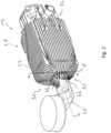
- the heat exchanger housing 12 shown in the figures is constructed as a metal casting and is constructed with a pot-like housing wall 14.
- the pot-like housing wall 14 comprises a The housing has an elongated peripheral wall 16 along the longitudinal axis L of the housing and a bottom wall 18 shaped like a dome or spherical segment in an axial end region.
- heat transfer fins 20 are provided which run in the direction of the longitudinal axis L of the housing and absorb heat from the exhaust gas flowing inside the heat exchanger housing 12.
- further heat transfer fins 22 are provided, via which heat can be transferred to the medium flowing around the heat exchanger housing 12, for example the air to be introduced into a vehicle interior.
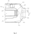
- This flows inside a housing 24 which accommodates the heat exchanger housing 12 and is formed, for example, from plastic material and leaves this in an outlet 26 formed adjacent to the bottom wall 18 of the heat exchanger housing 12.
- the heat transfer fins 22 provided on the outside of the heat exchanger housing 12 or the housing wall 14 are arranged in a total of four groups 28, 30, 32, 34 that follow one another in the circumferential direction.
- the heat transfer fins 22 assigned to these groups 28, 30, 32, 34 are arranged to extend along the housing longitudinal axis L and to run parallel to one another.
- the heat transfer fins 22 of immediately adjacent groups 28, 30, 32, 34 are arranged approximately orthogonally to one another, and the heat transfer fins 22 of diametrically opposite groups are arranged essentially parallel to one another.
- diagonal ribs 36, 38, 40, 42 are provided at least in the area of the outside of the bottom wall 18. These extend axially in the direction of the housing longitudinal axis L starting from the bottom wall 18 and radially outward starting from a central projection 44 which is essentially concentric with the housing longitudinal axis L and extends away from the bottom wall 18. Diagonal ribs 36, 38, 40, 42 which are immediately adjacent to one another enclose an angle of, for example, approximately 90°. Diagonal ribs 36, 38, 40, 42 which are diametrically opposite with respect to the housing longitudinal axis L run essentially parallel to one another.
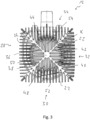
- Fig. 3 clearly shows that in each of the four groups of heat transfer fins 28, 30, 32, 34, a portion of the heat transfer fins 22 extends from the diagonal fins 36, 38, 40, 42. A portion of the heat transfer fins 22, in particular a central heat transfer fin of each group 28, 30, 32, 34, extends from the central extension 44.
- the heat exchanger housing 12 is manufactured as a metal cast component in a metal casting process using a casting mold.
- a sprue opening with a sprue cross-sectional area is provided in an area of a casting mold that is close to or opposite the bottom wall 18.
- This sprue cross-sectional area must have a certain minimum size in order to ensure that the hot and liquid metal material, generally liquefied aluminum or an aluminum alloy, can be quickly filled into the casting mold and completely distributed therein so that no cavities remain.
- a Fig. 2 shown blank which on the one hand comprises the heat exchanger housing 12 and on the other hand a sprue generally designated 45.
- the sprue cross-sectional area extends into the area of the heat transfer ribs 22 or some of them.
- the sprue 45 has rib sections 46 corresponding to the heat transfer ribs 22 or adjoining them.
- the channel formed in the casting mold or the opening formed in the casting mold for pouring in the metal material can be designed with an opening cross-section that widens in the direction of the cavity of the casting mold that receives the liquid metal material and essentially represents a negative of the heat exchanger housing 12.
- the sprue 45 is separated from the heat exchanger housing 12 by a cutting process, for example by sawing, so that a Fig. 3 remains on the axial end face 48 of the heat exchanger housing 12, which is outlined by a circle K drawn in a dash-dot line.
- the sprue 45 is separated in a plane E which is essentially orthogonal to the housing longitudinal axis L, as shown in Fig.
- This axial end face 48 which is approximately orthogonal to the longitudinal axis L of the housing, comprises on the one hand an end face region 50 of the central projection 44 and on the other hand comprises end face regions 52 of the diagonal ribs 36, 38, 40, 42 as well as end faces 54 of the heat transfer ribs 22 provided on the outside of the heat exchanger housing 12.
- This axial end face 48 also essentially corresponds to the sprue cross-sectional area provided in a casting mold, which can also be, for example, the maximum cross-sectional area of the opening in the casting mold that guides the metal material into the cavity of the casting mold.
- the sprue cross-sectional area extends into the area of the heat transfer fins 22, a comparatively large total cross-sectional area can be provided for filling the liquid metal material without the central projection 44 or a central sprue channel to be provided for forming the central projection 44 having to be provided with an excessively large cross-section, and without the diagonal fins 36, 38, 40, 42 having to be provided with an excessively large cross-section.
- a comparatively filigree structure is thus obtained which offers only a low flow resistance to the medium flowing on the outside of the heat exchanger housing 12.
- a large cross-sectional area for the medium to be heated to flow through is ensured due to a comparatively small cross-section of the central projection 44 and a comparatively small cross-sectional area of the diagonal fins 36, 38, 40, 42.
- a Fig. 3 The axial face 48 ensures a uniform introduction of the hot, liquid metal material into the mold, so that the Metal material can be distributed more evenly and quickly inside the mold.
Landscapes
- Engineering & Computer Science (AREA)
- Mechanical Engineering (AREA)
- Physics & Mathematics (AREA)
- Thermal Sciences (AREA)
- General Engineering & Computer Science (AREA)
- Chemical & Material Sciences (AREA)
- Combustion & Propulsion (AREA)
- Geometry (AREA)
- Molds, Cores, And Manufacturing Methods Thereof (AREA)
- Heat-Exchange Devices With Radiators And Conduit Assemblies (AREA)
Description
- Die vorliegende Erfindung betrifft ein Verfahren zur Herstellung eines Metallguss-Wärmetauschergehäuses für ein Fahrzeugheizgerät.
- Ein derartiges Metallguss-Wärmetauschergehäuse umfasst eine in Richtung einer Gehäuselängsachse langgestreckte topfartige Gehäusewandung. Um an der Außenseite der Gehäusewandung Wärme auf ein diese umströmendes Medium, zum Beispiel die in ein Fahrzeug einzuleitende Luft, übertragen zu können, sind an der Außenseite des Wärmetauschergehäuses Wärmeübertragungsrippen vorgesehen, welche sich sowohl im Bereich einer Umfangswandung der topfartigen Gehäusewandung, als auch im Bereich einer beispielsweise kugelsegmentartig ausgebildeten Bodenwandung der Gehäusewandung erstrecken.
- Aus der
DE 199 26 264 A1 ist ein mit einem Verfahren gemäß dem Oberbegriff des Anspruchs 1 mit einem stabartigen Anguss hergestelltes Wärmetauschergehäuse bekannt, welches eine in Richtung einer Gehäuselängsachse langgestreckte, topfartige Gehäusewandung mit einer kalottenartigen Bodenwandung aufweist. An einer Außenseite der Gehäusewandung sind in Richtung der Gehäuselängsachse sich erstreckende Rippen in sternförmiger Struktur angeordnet. Im Bereich der Bodenwandung sind die Rippen an einem stabartigen Anguss miteinander verbunden. - Es ist die Aufgabe der vorliegenden Erfindung, ein Verfahren zur Herstellung eines Metallguss-Wärmetauschergehäuses für ein Fahrzeugheizgerät vorzusehen, mit welchem ein Metallguss-Arbeitsvorgangs zur Herstellung eines strömungstechnisch vorteilhaften Wärmetauschergehäuses schnell und präzise durchgeführt werden kann.
- Erfindungsgemäß wird diese Aufgabe gelöst durch ein Verfahren gemäß Anspruch 1 zur Herstellung eines Metallguss-Wärmetauschergehäuses für ein Fahrzeugheizgerät mit einer in Richtung einer Gehäuselängsachse langgestreckten topfartigen Gehäusewandung und einer Mehrzahl von an einer Außenseite der Gehäusewandung im Bereich einer Umfangswandung und im Bereich einer Bodenwandung der Gehäusewandung in Richtung der Gehäuselängsachse verlaufenden Wärmeübertragungsrippen. Bei diesem Verfahren umfasst eine Anguss-Querschnittsfläche wenigstens einen Teil der Wärmeübertragungsrippen. Nach Durchführung eines Metallguss-Arbeitsvorgangs und Abkühlen des Metallmaterials wird ein Anguss derart von dem Wärmetauschergehäuse abgetrennt, dass eine zur Gehäuselängsachse im Wesentlichen orthogonale und sich in den Bereich wenigstens eines Teils der Wärmeübertragungsrippen erstreckende axiale Stirnfläche des Wärmetauschergehäuses gebildet wird.
- Die Anguss-Querschnittsfläche ist diejenige Querschnittsfläche einer in einer Gussform vorgesehenen Öffnung, durch welche das flüssige Metallmaterial in die zur Herstellung des Wärmetauschergehäuses eingesetzte Gussform eingegossen wird.
- Um das heiße, flüssige Metallmaterial möglichst schnell in die Form eingießen zu können und damit alle Formhohlräume vollständig und gleichmäßig mit dem flüssigen Metallmaterial füllen zu können, ist es erforderlich, eine ausreichend große Anguss-Querschnittsfläche bereitzustellen. Dadurch, dass gemäß den Prinzipien der vorliegenden Erfindung diese Anguss-Querschnittsfläche sich bis in den Bereich der Wärmeübertragungsrippen erstreckt, kann auch zumindest ein Teil der Wärmeübertragungsrippen-Querschnittsfläche zum Einleiten von flüssigem Metallmaterial genutzt werden.
- Um eine ausreichend große Anguss-Querschnittsfläche bereitstellen zu können, wird weiter vorgeschlagen, dass die Anguss-Querschnittsfläche einen zentralen Anguss-Kanal und, ausgehend von dem zentralen Anguss-Kanal, eine Mehrzahl von Diagonalrippen umfasst. Da gemäß den Prinzipien der vorliegenden Erfindung die Anguss-Querschnittsfläche auch Teile der Wärmeübertragungsrippen umfasst bzw. sich in den Bereich der Wärmeübertragungsrippen erstreckt, kann ein im Bereich des zentralen Anguss-Kanals bereitzustellender Teil der Anguss-Querschnittsfläche bzw. ein im Bereich der Diagonalrippen bereitzustellender Teil der Querschnittsfläche verringert werden.
- Beispielsweise kann vorgesehen sein, dass, ausgehend von dem zentralen Anguss-Kanal, sich vier Diagonalrippen erstrecken. Dabei können jeweils zwei Diagonalrippen sich zueinander diametral von dem zentralen Anguss-Kanal weg erstrecken oder/und einander in Umfangsrichtung unmittelbar benachbarte Diagonalrippen zueinander im Wesentlichen orthogonal angeordnet sein.
- Um eine Verknüpfung der verschiedenen die gesamte Anguss-Querschnittsfläche bereitstellenden Querschnittsflächenanteile zu erreichen, kann im Bereich der Anguss-Querschnittsfläche wenigstens ein Teil der Wärmeübertragungsrippen sich ausgehend vom zentralen Anguss-Kanal erstrecken, oder/und kann im Bereich der Anguss-Querschnittsfläche wenigstens ein Teil der Wärmeübertragungsrippen sich ausgehend von den Diagonalrippen erstrecken.
- Um eine große Oberfläche für die Übertragung von Wärme auf ein das Wärmetauschergehäuse umströmendes Medium bereit stellen zu können, wird vorgeschlagen, dass die Wärmeübertragungsrippen in mehreren Gruppen von Wärmeübertragungsrippen angeordnet sind, wobei die Wärmeübertragungsrippen jeder Gruppe von Wärmeübertragungsrippen zueinander im Wesentlichen parallel angeordnet sind.
- Erfindungsgemäß kann vorgesehen sein, dass beim Abtrennen des Angusses die axiale Stirnfläche sich in die Diagonalrippen erstreckend gebildet wird.
- Beim Abtrennen des Angusses kann die axiale Stirnfläche gebildet werden mit einem Stirnflächenbereich eines Zentral-Ansatzes oder/und mit Stirnflächenbereichen der Diagonalrippen.
- Ferner kann beim Abtrennen des Angusses die axiale Stirnfläche mit in die Wärmeübertragungsrippen der Gruppen von zueinander im Wesentlichen parallel sich erstreckenden Wärmeübertragungsrippen sich erstreckenden Stirnflächen gebildet werden.
- Ein mit einem erfindungsgemäßen Verfahren hergestelltes Metallguss-Wärmetauschergehäuse umfasst eine in Richtung einer Gehäuselängsachse langgestreckte topfartige Gehäusewandung und eine Mehrzahl von an einer Außenseite der Gehäusewandung im Bereich einer Umfangswandung und im Bereich einer
Bodenwandung der Gehäusewandung in Richtung der Gehäuselängsachse verlaufenden Wärmeübertragungsrippen, wobei eine durch Abtrennen von Metallmaterial gebildete, zur Gehäuselängsachse im Wesentlichen orthogonale axiale Stirnfläche des Wärmetauschergehäuses sich in den Bereich wenigstens eines Teils der Wärmeübertragungsrippen erstreckt. - Von einem sich zur Gehäuselängsachse im Wesentlichen koaxial von der Bodenwandung erstreckenden Zentral-Ansatz können Diagonalrippen nach radial außen verlaufen, und die durch Abtrennen von Metallmaterial gebildete axiale Stirnfläche kann sich in den Bereich der Diagonalrippen erstrecken.
- Die vorliegende Erfindung wird nachfolgend mit Bezug auf die beiliegenden Figuren detailliert beschrieben. Es zeigt:
- Fig. 1
- eine perspektivische Ansicht eines Metallguss-Wärmetauschergehäuses für ein brennstoffbetriebenes Fahrzeugheizgerät;
- Fig. 2
- das Metallguss-Wärmetauschergehäuse der
Fig. 1 mit einem bei einem Metallguss-Arbeitsvorgang gebildeten und von dem Wärmetauschergehäuse zu trennenden Anguss; - Fig. 3
- das Metallguss-Wärmetauschergehäuse der
Fig. 1 in Blickrichtung III inFig. 1 ; - Fig. 4
- eine Teil-Längsschnittansicht des Wärmetauschergehäuses der
Fig. 1 in einem Gehäuse eines Fahrzeugheizgeräts; - Fig. 5
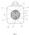
- eine Axialansicht des in dem Gehäuse angeordneten Wärmetauschergehäuses in Blickrichtung V in
Fig. 4 . - Das in den Figuren dargestellte als Metallgussteil aufgebaute Wärmetauschergehäuse 12 ist mit einer topfartigen Gehäusewandung 14 aufgebaut. Die topfartige Gehäusewandung 14 umfasst eine in Richtung einer Gehäuselängsachse L langgestreckte Umfangswandung 16 und in einem axialen Endbereich eine kalottenartig bzw. kugelsegmentartig geformte Bodenwandung 18. An der Innenseite der Gehäusewandung 14 sind in Richtung der Gehäuselängsachse L verlaufende Wärmeübertragungsrippen 20 vorgesehen, welche Wärme von dem im Inneren des Wärmetauschergehäuses 12 strömenden Abgas aufnehmen. An der Außenseite der Gehäusewandung 14 sind weitere Wärmeübertragungsrippen 22 vorgesehen, über welche Wärme auf das das Wärmetauschergehäuse 12 umströmende Medium, also beispielsweise die in einen Fahrzeuginnenraum einzuleitende Luft, übertragen werden kann. Diese strömt im Inneren eines das Wärmetauschergehäuse 12 aufnehmenden und beispielsweise aus Kunststoffmaterial geformten Gehäuses 24 und verlässt dieses in einem anschließend an die Bodenwandung 18 des Wärmetauschergehäuses 12 gebildeten Auslass 26.
- Die an der Außenseite des Wärmetauschergehäuses 12 bzw. der Gehäusewandung 14 vorgesehenen Wärmeübertragungsrippen 22 sind in insgesamt vier in Umfangsrichtung aufeinanderfolgenden Gruppen 28, 30, 32, 34 angeordnet. In jeder dieser Gruppen 28, 30, 32, 34 sind die diesen Gruppen 28, 30, 32, 34 zugeordneten Wärmeübertragungsrippen 22 entlang der Gehäuselängsachse L sich erstreckend und zueinander parallel verlaufend angeordnet. Die Wärmeübertragungsrippen 22 einander unmittelbar benachbarter Gruppen 28, 30, 32, 34 sind zueinander näherungsweise orthogonal angeordnet, um die Wärmeübertragungsrippen 22 einander diametral gegenüberliegender Gruppen sind zueinander im Wesentlichen parallel angeordnet.
- Um diese Struktur zu erhalten, sind zumindest im Bereich der Außenseite der Bodenwandung 18 Diagonalrippen 36, 38, 40, 42 vorgesehen. Diese erstrecken sich in Richtung der Gehäuselängsachse L ausgehend von der Bodenwandung 18 axial und ausgehend von einem zur Gehäuselängsachse L im Wesentlichen konzentrischen und von der Bodenwandung 18 sich weg erstreckenden Zentral-Ansatz 44 nach radial außen. Einander unmittelbar benachbarte Diagonalrippen 36, 38, 40, 42 schließen einen Winkel von beispielsweise etwa 90° ein. Einander bezüglich der Gehäuselängsachse L diametral gegenüberliegende Diagonalrippen 36, 38, 40, 42 verlaufen zueinander im Wesentlichen parallel.
- Die
Fig. 3 zeigt deutlich, dass bei jeder der vier Gruppen von Wärmeübertragungsrippen 28, 30, 32, 34 ein Teil der Wärmeübertragungsrippen 22 sich ausgehend von den Diagonalrippen 36, 38, 40, 42 erstreckt. Ein Teil der Wärmeübertragungsrippen 22, insbesondere eine jeweils zentrale Wärmeübertragungsrippe jeder Gruppe 28, 30, 32, 34, erstreckt sich ausgehend von dem Zentral-Ansatz 44. - Das Wärmetauschergehäuse 12 wird als Metallguss-Bauteil in einem Metallguss-Arbeitsvorgang unter Verwendung einer Gussform hergestellt. Um das heiße, flüssige Metallmaterial in die Gussform einfüllen zu können, ist in einem der Bodenwandung 18 nahe liegenden bzw. gegenüberliegenden Bereich einer Gussform eine Angussöffnung mit einer Anguss-Querschnittsfläche bereitgestellt. Diese Anguss-Querschnittsfläche muss eine bestimmte Mindestgröße aufweisen, um dafür Sorge tragen zu können, dass das heiße und flüssige Metallmaterial, im Allgemeinen verflüssigtes Aluminium oder eine Aluminiumlegierung, schnell in die Gussform eingefüllt und darin vollständig verteilt werden kann, so dass keine Hohlräume verbleiben. Nach dem Auskühlen des eingefüllten Metallmaterials verbleibt ein in
Fig. 2 dargestellter Rohling, welcher einerseits das Wärmetauschergehäuse 12 und andererseits einen allgemein mit 45 bezeichneten Anguss umfasst. - Bei dem erfindungsgemäßen Verfahren ist dafür gesorgt, dass die Anguss-Querschnittsfläche sich bis in den Bereich der bzw. einiger Wärmeübertragungsrippen 22 erstreckt. Dadurch weist der Anguss 45 den Wärmeübertragungsrippen 22 entsprechende bzw. an diese anschließende Rippenabschnitte 46 auf. Um diese Struktur zu erhalten, kann der in der Gussform gebildete Kanal bzw. die in der Gussform gebildete Öffnung zum Eingießen des Metallmaterials mit in Richtung zu dem das flüssige Metallmaterial aufnehmenden und im Wesentlichen ein Negativ des Wärmetauschergehäuses 12 darstellenden Hohlraum der Gussform sich erweiternden Öffnungsquerschnitt ausgebildet sein.
- Nach dem Auskühlen des Metallmaterials wird der Anguss 45 durch einen Schneidevorgang, beispielsweise durch Absägen, von dem Wärmetauschergehäuse 12 getrennt, so dass eine in
Fig. 3 von einem in Strich-Punkt-Linie eingezeichneten Kreis K umrissene axiale Stirnfläche 48 des Wärmetauschergehäuses 12 verbleibt. Dazu wird der Anguss 45 in einer zur Gehäuselängsachse L im Wesentlichen Orthogonale Ebene E abgetrennt, wie inFig. 2 veranschaulicht. Diese zur Gehäuselängsachse L näherungsweise orthogonale axiale Stirnfläche 48 umfasst einerseits einen Stirnflächenbereich 50 des Zentral-Ansatzes 44 und umfasst andererseits Stirnflächenbereiche 52 der Diagonalrippen 36, 38, 40, 42 sowie auch Stirnflächen 54 der an der Außenseite des Wärmetauschergehäuses 12 vorgesehenen Wärmeübertragungsrippen 22. Diese axiale Stirnfläche 48 entspricht im Wesentlichen auch der in einer Gussform vorgesehenen Anguss-Querschnittsfläche, welche beispielsweise auch die maximale Querschnittsfläche der das Metallmaterial in den Hohlraum der Gussform leitenden Öffnung in der Gussform sein kann. - Da bei dem erfindungsgemäß durchzuführenden Verfahren die Anguss-Querschnittsfläche sich bis in den Bereich der Wärmeübertragungsrippen 22 erstreckt, kann eine vergleichsweise große Gesamt-Querschnittsfläche zum Einfüllen des flüssigen Metallmaterials bereitgestellt werden, ohne dass der Zentral-Ansatz 44 bzw. ein zum Bilden des Zentral-Ansatzes 44 vorzusehender zentraler Anguss-Kanal mit übermäßig großem Querschnitt bereitgestellt werden muss, und ohne dass die Diagonalrippen 36, 38, 40, 42 mit übermäßig großem Querschnitt bereitgestellt werden müssen. Es wird somit eine vergleichsweise filigrane Struktur erhalten, welche dem an der Außenseite des Wärmetauschergehäuses 12 strömenden Medium nur einen geringen Strömungswiderstand entgegensetzt. Insbesondere wird im Bereich des Auslasses 26 aufgrund eines vergleichsweise geringen Querschnitts des Zentral-Ansatzes 44 und einer vergleichsweise geringen Querschnittsfläche der Diagonalrippen 36, 38, 40, 42 eine große Querschnittsfläche zum Durchströmen für das zu erwärmende Medium gewährleistet. Gleichzeitig wird eine auf die in
Fig. 3 erkennbare axiale Stirnfläche 48 verteilte gleichmäßige Einleitung des heißen, flüssigen Metallmaterials in die Gussform gewährleistet, so dass auch das Metallmaterial im Inneren der Gussform gleichmäßiger und schneller verteilt werden kann.
Claims (8)
- Verfahren zur Herstellung eines Metallguss-Wärmetauschergehäuses (12) für ein Fahrzeugheizgerät mit einer in Richtung einer Gehäuselängsachse (L) langgestreckten topfartigen Gehäusewandung (14) und einer Mehrzahl von an einer Außenseite der Gehäusewandung (14) im Bereich einer Umfangswandung (16) und im Bereich einer Bodenwandung (18) der Gehäusewandung (14) in Richtung der Gehäuselängsachse (L) verlaufenden Wärmeübertragungsrippen (22), welches Verfahren die Schritte umfasst:- in einem Metallguss-Arbeitsvorgang, Einfüllen von flüssigem Metallmaterial in eine Gussform durch eine in einer Gussform in einem der Bodenwandung nahe liegenden Bereich vorgesehene Angussöffnung mit einer Anguss-Querschnittsfläche,- nach Durchführung des Metallguss-Arbeitsvorgangs, Abkühlen des Metallmaterials- nach dem Abkühlen des Metallmaterials, Abtrennen eines Angusses (45) von dem Wärmetauschergehäuse (12) derart, dass eine der Anguss-Querschnittsfläche entsprechende, zur Gehäuselängsachse (L) im Wesentlichen orthogonale axiale Stirnfläche (48) des Wärmetauschergehäuses (12) gebildet wird,dadurch gekennzeichnet, dass die Anguss-Querschnittsfläche wenigstens einen Teil der Wärmeübertragungsrippen (22) umfasst, und dass die der Anguss-Querschnittsfläche entsprechende, zur Gehäuselängsachse (L) im Wesentlichen orthogonale axiale Stirnfläche (48) des Wärmetauschergehäuses (12) sich in den Bereich wenigstens eines Teils der Wärmeübertragungsrippen (22) erstreckt.
- Verfahren nach Anspruch 1, dadurch gekennzeichnet, dass die Anguss-Querschnittsfläche einen zentralen Anguss-Kanal und, ausgehend von dem zentralen Anguss-Kanal, eine Mehrzahl von Diagonalrippen (36, 38, 40, 42) umfasst.
- Verfahren nach Anspruch 2, dadurch gekennzeichnet, dass, ausgehend von dem zentralen Anguss-Kanal sich vier Diagonalrippen (36, 38, 40, 42) erstrecken, vorzugsweise wobei jeweils zwei Diagonalrippen (36, 38, 40, 42) sich zueinander diametral von dem zentralen Anguss-Kanal weg erstrecken oder/und einander in Umfangsrichtung unmittelbar benachbarte Diagonalrippen (36, 38, 40, 42) zueinander im Wesentlichen orthogonal angeordnet sind.
- Verfahren nach Anspruch 2 oder 3, dadurch gekennzeichnet, dass im Bereich der Anguss-Querschnittsfläche wenigstens ein Teil der Wärmeübertragungsrippen (22) sich ausgehend vom zentralen Anguss-Kanal erstreckt, oder/und dass im Bereich der Anguss-Querschnittsfläche wenigstens ein Teil der Wärmeübertragungsrippen (22) sich ausgehend von den Diagonalrippen (36, 38, 40, 42) erstreckt.
- Verfahren nach einem der vorangehenden Ansprüche, dadurch gekennzeichnet, dass die Wärmeübertragungsrippen (22) in mehreren Gruppen (28, 30, 32, 34) von Wärmeübertragungsrippen (22) angeordnet sind, wobei die Wärmeübertragungsrippen (22) jeder Gruppe (28, 30, 32, 34) von Wärmeübertragungsrippen (22) zueinander im Wesentlichen parallel angeordnet sind.
- Verfahren nach Anspruch 2, oder nach einem der Ansprüche 3-5, sofern auf Anspruch 2 rückbezogen, dadurch gekennzeichnet, dass beim Abtrennen des Angusses (45) die axiale Stirnfläche (48) sich in die Diagonalrippen (36, 38, 40, 42) erstreckend gebildet wird.
- Verfahren nach Anspruch 6, dadurch gekennzeichnet, dass beim Abtrennen des Angusses (45) die axiale Stirnfläche (48) gebildet wird mit einem Stirnflächenbereich (50) eines Zentral-Ansatzes (44) oder/und mit Stirnflächenbereichen (52) der Diagonalrippen (36, 38, 40, 42).
- Verfahren nach Anspruch 5 und Anspruch 6 oder 7, dadurch gekennzeichnet, dass beim Abtrennen des Angusses (45) die axiale Stirnfläche (48) mit in die Wärmeübertragungsrippen (22) der Gruppen (28, 30, 32, 34) von zueinander im Wesentlichen parallel sich erstreckenden Wärmeübertragungsrippen (22) sich erstreckenden Stirnflächen (54) gebildet wird.
Applications Claiming Priority (1)
| Application Number | Priority Date | Filing Date | Title |
|---|---|---|---|
| DE102020105941.8A DE102020105941A1 (de) | 2020-03-05 | 2020-03-05 | Verfahren zur Herstellung eines Metallguss-Wärmetauschergehäuses für ein Fahrzeugheizgerät |
Publications (2)
| Publication Number | Publication Date |
|---|---|
| EP3875294A1 EP3875294A1 (de) | 2021-09-08 |
| EP3875294B1 true EP3875294B1 (de) | 2025-01-08 |
Family
ID=74494786
Family Applications (1)
| Application Number | Title | Priority Date | Filing Date |
|---|---|---|---|
| EP21154538.9A Active EP3875294B1 (de) | 2020-03-05 | 2021-02-01 | Verfahren zur herstellung eines metallguss-wärmetauschergehäuses für ein fahrzeugheizgerät |
Country Status (6)
| Country | Link |
|---|---|
| US (1) | US11760164B2 (de) |
| EP (1) | EP3875294B1 (de) |
| CN (1) | CN113351830B (de) |
| DE (1) | DE102020105941A1 (de) |
| FI (1) | FI3875294T3 (de) |
| RU (1) | RU2760846C1 (de) |
Family Cites Families (14)
| Publication number | Priority date | Publication date | Assignee | Title |
|---|---|---|---|---|
| SU84359A1 (ru) * | 1948-09-22 | 1949-11-30 | И.Е. Брайнин | Надставка фасонно-конической прибыли дл квадратных слитков спокойной стали |
| DE3509349A1 (de) | 1985-03-15 | 1986-09-18 | Webasto-Werk W. Baier GmbH & Co, 8035 Gauting | Waermetauscher fuer heizgeraete |
| SU1444058A1 (ru) * | 1986-12-02 | 1988-12-15 | Всесоюзный Научно-Исследовательский Институт Технологии Арматуростроения | Прибыль дл питани отливок,имеющих несколько тепловых узлов |
| DE19734814C1 (de) | 1997-08-12 | 1999-01-14 | Webasto Thermosysteme Gmbh | Brennstoffbetriebene Heizvorrichtung mit optimierter Verbrennungsgasführung |
| DE19926264B4 (de) | 1999-06-09 | 2013-05-16 | J. Eberspächer GmbH & Co. KG | Heizgerät |
| US6845810B2 (en) * | 2002-10-11 | 2005-01-25 | General Motors Corporation | Lost-foam casting apparatus for improved recycling of sprue-metal |
| DE102011079018A1 (de) * | 2011-07-12 | 2013-01-17 | J. Eberspächer GmbH & Co. KG | Fahrzeugheizgerät |
| DE102015106600A1 (de) * | 2015-04-29 | 2016-11-03 | Eberspächer Climate Control Systems GmbH & Co. KG | Fahrzeugheizgerät |
| WO2017148457A1 (de) * | 2016-03-01 | 2017-09-08 | Ferrofacta Gmbh | Druckgussdüsensystem |
| DE102017100133A1 (de) * | 2017-01-05 | 2018-07-05 | Eberspächer Climate Control Systems GmbH & Co. KG | Wärmetauschergehäuse |
| DE102017125783B4 (de) * | 2017-11-06 | 2019-09-05 | Eberspächer Climate Control Systems GmbH & Co. KG | Fahrzeugheizgerät |
| DE102018117213A1 (de) * | 2018-07-17 | 2020-01-23 | Eberspächer Climate Control Systems GmbH & Co. KG | Fahrzeugheizgerät |
| DE102018120030A1 (de) * | 2018-08-17 | 2020-02-20 | Eberspächer Climate Control Systems GmbH & Co. KG | Fahrzeugheizgerät |
| DE102019110949A1 (de) | 2019-04-29 | 2020-10-29 | Eberspächer Climate Control Systems GmbH | Fahrzeugheizgerät |
-
2020
- 2020-03-05 DE DE102020105941.8A patent/DE102020105941A1/de active Pending
-
2021
- 2021-02-01 EP EP21154538.9A patent/EP3875294B1/de active Active
- 2021-02-01 FI FIEP21154538.9T patent/FI3875294T3/fi active
- 2021-02-03 RU RU2021102459A patent/RU2760846C1/ru active
- 2021-03-03 US US17/191,353 patent/US11760164B2/en active Active
- 2021-03-05 CN CN202110243835.XA patent/CN113351830B/zh active Active
Also Published As
| Publication number | Publication date |
|---|---|
| DE102020105941A1 (de) | 2021-09-09 |
| FI3875294T3 (fi) | 2025-02-19 |
| CN113351830A (zh) | 2021-09-07 |
| RU2760846C1 (ru) | 2021-11-30 |
| EP3875294A1 (de) | 2021-09-08 |
| US20210276399A1 (en) | 2021-09-09 |
| US11760164B2 (en) | 2023-09-19 |
| CN113351830B (zh) | 2023-05-23 |
Similar Documents
| Publication | Publication Date | Title |
|---|---|---|
| DE102016202416B4 (de) | Rotorwellenanordnung und Verfahren zu dessen Herstellung | |
| DE60218217T2 (de) | Verfahren zur herstellung eines rotors eines elektromotors | |
| DE69404872T2 (de) | Kühlungsverfahren und -vorrichtung für ein Extrudergehäuse | |
| DE69735245T2 (de) | Kurbelarm für ein Fahrrad und Verfahren zur Herstellung | |
| EP2064012A1 (de) | Luftkompressor mit kurbelgehäuse aus aluminiumguss | |
| WO2014032756A1 (de) | Verfahren zur herstellung eines verbundbauteils sowie ein verbundbauteil | |
| DE102013020469A1 (de) | Wärmeübertrager und Verfahren zum Herstellen eines Wärmeübertragers | |
| DE102019211440A1 (de) | Motorgehäuse und Verfahren zur Herstellung eines Motorgehäuses | |
| EP3875294B1 (de) | Verfahren zur herstellung eines metallguss-wärmetauschergehäuses für ein fahrzeugheizgerät | |
| DE69608028T2 (de) | Verfahren und Vorrichtung zur gerichtete Erstarrung von Teilen mit integrierten Elementen | |
| DE102016113620A1 (de) | Verfahren zur Herstellung eines Gehäusebauteils eines Verbrennungsmotors | |
| DE102019211348A1 (de) | Gehäuseanordnung für eine oder mehrere elektrochemische Zellen | |
| DE69708354T2 (de) | Aus Leichtmetall gegossener, im wesentlichen zylindrischer Wärmetauscher | |
| EP1204516B1 (de) | Verfahren zur herstellung eines hohlkörpers in schmelzkerntechnik | |
| DE3707256C1 (en) | Core for the casting of grey cast iron cylinder blocks | |
| EP1681519A2 (de) | Wärmetauscherkörper und Fahrzeugheizgerät mit einem Wärmetauscherkörper | |
| EP1053089B1 (de) | Vorrichtung zum herstellen von fluidbehältern | |
| DE102004028426B4 (de) | Einsatzkern und Verfahren zur Herstellung eines Zylinders für einen Verbrennungsmotor mit dem Einsatzkern | |
| EP1589298B1 (de) | Heizgerät, insbesondere für ein Fahrzeug | |
| DE102017125209A1 (de) | Gehäuseeinrichtung für eine elektrische Maschine und Verfahren | |
| DE102017206984A1 (de) | Elektrische Maschine, insbesondere für ein Kraftfahrzeug, sowie Verfahren zum Herstellen einer solchen elektrischen Maschine | |
| DE102012105280A1 (de) | Verfahren zur Herstellung eines Verbundbauteils | |
| DE112018003862T5 (de) | Gussform und herstellungsverfahren eines gussteils | |
| DE102004043903A1 (de) | Wärmetauscher | |
| DE102011053422A1 (de) | Druckgussform und Verfahren zur Herstellung eines Gehäuseteils einer Wärmeübertragungsvorrichtung |
Legal Events
| Date | Code | Title | Description |
|---|---|---|---|
| PUAI | Public reference made under article 153(3) epc to a published international application that has entered the european phase |
Free format text: ORIGINAL CODE: 0009012 |
|
| STAA | Information on the status of an ep patent application or granted ep patent |
Free format text: STATUS: THE APPLICATION HAS BEEN PUBLISHED |
|
| AK | Designated contracting states |
Kind code of ref document: A1 Designated state(s): AL AT BE BG CH CY CZ DE DK EE ES FI FR GB GR HR HU IE IS IT LI LT LU LV MC MK MT NL NO PL PT RO RS SE SI SK SM TR |
|
| STAA | Information on the status of an ep patent application or granted ep patent |
Free format text: STATUS: REQUEST FOR EXAMINATION WAS MADE |
|
| 17P | Request for examination filed |
Effective date: 20220309 |
|
| RBV | Designated contracting states (corrected) |
Designated state(s): AL AT BE BG CH CY CZ DE DK EE ES FI FR GB GR HR HU IE IS IT LI LT LU LV MC MK MT NL NO PL PT RO RS SE SI SK SM TR |
|
| STAA | Information on the status of an ep patent application or granted ep patent |
Free format text: STATUS: EXAMINATION IS IN PROGRESS |
|
| 17Q | First examination report despatched |
Effective date: 20240621 |
|
| 17Q | First examination report despatched |
Effective date: 20240626 |
|
| GRAP | Despatch of communication of intention to grant a patent |
Free format text: ORIGINAL CODE: EPIDOSNIGR1 |
|
| STAA | Information on the status of an ep patent application or granted ep patent |
Free format text: STATUS: GRANT OF PATENT IS INTENDED |
|
| GRAS | Grant fee paid |
Free format text: ORIGINAL CODE: EPIDOSNIGR3 |
|
| GRAA | (expected) grant |
Free format text: ORIGINAL CODE: 0009210 |
|
| STAA | Information on the status of an ep patent application or granted ep patent |
Free format text: STATUS: THE PATENT HAS BEEN GRANTED |
|
| INTG | Intention to grant announced |
Effective date: 20241108 |
|
| P01 | Opt-out of the competence of the unified patent court (upc) registered |
Free format text: CASE NUMBER: APP_62360/2024 Effective date: 20241122 |
|
| AK | Designated contracting states |
Kind code of ref document: B1 Designated state(s): AL AT BE BG CH CY CZ DE DK EE ES FI FR GB GR HR HU IE IS IT LI LT LU LV MC MK MT NL NO PL PT RO RS SE SI SK SM TR |
|
| REG | Reference to a national code |
Ref country code: GB Ref legal event code: FG4D Free format text: NOT ENGLISH |
|
| REG | Reference to a national code |
Ref country code: CH Ref legal event code: EP |
|
| REG | Reference to a national code |
Ref country code: DE Ref legal event code: R096 Ref document number: 502021006324 Country of ref document: DE |
|
| REG | Reference to a national code |
Ref country code: IE Ref legal event code: FG4D Free format text: LANGUAGE OF EP DOCUMENT: GERMAN |
|
| REG | Reference to a national code |
Ref country code: FI Ref legal event code: FGE |
|
| REG | Reference to a national code |
Ref country code: SE Ref legal event code: TRGR |
|
| PGFP | Annual fee paid to national office [announced via postgrant information from national office to epo] |
Ref country code: AT Payment date: 20250417 Year of fee payment: 5 |
|
| REG | Reference to a national code |
Ref country code: LT Ref legal event code: MG9D |
|
| REG | Reference to a national code |
Ref country code: NL Ref legal event code: MP Effective date: 20250108 |
|
| PG25 | Lapsed in a contracting state [announced via postgrant information from national office to epo] |
Ref country code: NL Free format text: LAPSE BECAUSE OF FAILURE TO SUBMIT A TRANSLATION OF THE DESCRIPTION OR TO PAY THE FEE WITHIN THE PRESCRIBED TIME-LIMIT Effective date: 20250108 |
|
| PG25 | Lapsed in a contracting state [announced via postgrant information from national office to epo] |
Ref country code: RS Free format text: LAPSE BECAUSE OF FAILURE TO SUBMIT A TRANSLATION OF THE DESCRIPTION OR TO PAY THE FEE WITHIN THE PRESCRIBED TIME-LIMIT Effective date: 20250408 |
|
| PG25 | Lapsed in a contracting state [announced via postgrant information from national office to epo] |
Ref country code: PL Free format text: LAPSE BECAUSE OF FAILURE TO SUBMIT A TRANSLATION OF THE DESCRIPTION OR TO PAY THE FEE WITHIN THE PRESCRIBED TIME-LIMIT Effective date: 20250108 |
|
| PG25 | Lapsed in a contracting state [announced via postgrant information from national office to epo] |
Ref country code: ES Free format text: LAPSE BECAUSE OF FAILURE TO SUBMIT A TRANSLATION OF THE DESCRIPTION OR TO PAY THE FEE WITHIN THE PRESCRIBED TIME-LIMIT Effective date: 20250108 |
|
| PG25 | Lapsed in a contracting state [announced via postgrant information from national office to epo] |
Ref country code: IS Free format text: LAPSE BECAUSE OF FAILURE TO SUBMIT A TRANSLATION OF THE DESCRIPTION OR TO PAY THE FEE WITHIN THE PRESCRIBED TIME-LIMIT Effective date: 20250508 Ref country code: NO Free format text: LAPSE BECAUSE OF FAILURE TO SUBMIT A TRANSLATION OF THE DESCRIPTION OR TO PAY THE FEE WITHIN THE PRESCRIBED TIME-LIMIT Effective date: 20250408 |
|
| PG25 | Lapsed in a contracting state [announced via postgrant information from national office to epo] |
Ref country code: HR Free format text: LAPSE BECAUSE OF FAILURE TO SUBMIT A TRANSLATION OF THE DESCRIPTION OR TO PAY THE FEE WITHIN THE PRESCRIBED TIME-LIMIT Effective date: 20250108 |
|
| PG25 | Lapsed in a contracting state [announced via postgrant information from national office to epo] |
Ref country code: LV Free format text: LAPSE BECAUSE OF FAILURE TO SUBMIT A TRANSLATION OF THE DESCRIPTION OR TO PAY THE FEE WITHIN THE PRESCRIBED TIME-LIMIT Effective date: 20250108 Ref country code: PT Free format text: LAPSE BECAUSE OF FAILURE TO SUBMIT A TRANSLATION OF THE DESCRIPTION OR TO PAY THE FEE WITHIN THE PRESCRIBED TIME-LIMIT Effective date: 20250508 |
|
| PG25 | Lapsed in a contracting state [announced via postgrant information from national office to epo] |
Ref country code: BG Free format text: LAPSE BECAUSE OF FAILURE TO SUBMIT A TRANSLATION OF THE DESCRIPTION OR TO PAY THE FEE WITHIN THE PRESCRIBED TIME-LIMIT Effective date: 20250108 Ref country code: GR Free format text: LAPSE BECAUSE OF FAILURE TO SUBMIT A TRANSLATION OF THE DESCRIPTION OR TO PAY THE FEE WITHIN THE PRESCRIBED TIME-LIMIT Effective date: 20250409 |
|
| REG | Reference to a national code |
Ref country code: CH Ref legal event code: PL |
|
| PG25 | Lapsed in a contracting state [announced via postgrant information from national office to epo] |
Ref country code: SM Free format text: LAPSE BECAUSE OF FAILURE TO SUBMIT A TRANSLATION OF THE DESCRIPTION OR TO PAY THE FEE WITHIN THE PRESCRIBED TIME-LIMIT Effective date: 20250108 |
|
| REG | Reference to a national code |
Ref country code: DE Ref legal event code: R097 Ref document number: 502021006324 Country of ref document: DE |
|
| PG25 | Lapsed in a contracting state [announced via postgrant information from national office to epo] |
Ref country code: DK Free format text: LAPSE BECAUSE OF FAILURE TO SUBMIT A TRANSLATION OF THE DESCRIPTION OR TO PAY THE FEE WITHIN THE PRESCRIBED TIME-LIMIT Effective date: 20250108 |
|
| PG25 | Lapsed in a contracting state [announced via postgrant information from national office to epo] |
Ref country code: MC Free format text: LAPSE BECAUSE OF FAILURE TO SUBMIT A TRANSLATION OF THE DESCRIPTION OR TO PAY THE FEE WITHIN THE PRESCRIBED TIME-LIMIT Effective date: 20250108 |
|
| PG25 | Lapsed in a contracting state [announced via postgrant information from national office to epo] |
Ref country code: LU Free format text: LAPSE BECAUSE OF NON-PAYMENT OF DUE FEES Effective date: 20250201 |
|
| PG25 | Lapsed in a contracting state [announced via postgrant information from national office to epo] |
Ref country code: CH Free format text: LAPSE BECAUSE OF NON-PAYMENT OF DUE FEES Effective date: 20250228 |
|
| PG25 | Lapsed in a contracting state [announced via postgrant information from national office to epo] |
Ref country code: EE Free format text: LAPSE BECAUSE OF FAILURE TO SUBMIT A TRANSLATION OF THE DESCRIPTION OR TO PAY THE FEE WITHIN THE PRESCRIBED TIME-LIMIT Effective date: 20250108 |
|
| PG25 | Lapsed in a contracting state [announced via postgrant information from national office to epo] |
Ref country code: RO Free format text: LAPSE BECAUSE OF FAILURE TO SUBMIT A TRANSLATION OF THE DESCRIPTION OR TO PAY THE FEE WITHIN THE PRESCRIBED TIME-LIMIT Effective date: 20250108 |
|
| PG25 | Lapsed in a contracting state [announced via postgrant information from national office to epo] |
Ref country code: SK Free format text: LAPSE BECAUSE OF FAILURE TO SUBMIT A TRANSLATION OF THE DESCRIPTION OR TO PAY THE FEE WITHIN THE PRESCRIBED TIME-LIMIT Effective date: 20250108 |
|
| PLBE | No opposition filed within time limit |
Free format text: ORIGINAL CODE: 0009261 |
|
| STAA | Information on the status of an ep patent application or granted ep patent |
Free format text: STATUS: NO OPPOSITION FILED WITHIN TIME LIMIT |
|
| REG | Reference to a national code |
Ref country code: BE Ref legal event code: MM Effective date: 20250228 |
|
| 26N | No opposition filed |
Effective date: 20251009 |
|
| GBPC | Gb: european patent ceased through non-payment of renewal fee |
Effective date: 20250408 |
|
| PG25 | Lapsed in a contracting state [announced via postgrant information from national office to epo] |
Ref country code: GB Free format text: LAPSE BECAUSE OF NON-PAYMENT OF DUE FEES Effective date: 20250408 |
|
| PG25 | Lapsed in a contracting state [announced via postgrant information from national office to epo] |
Ref country code: FR Free format text: LAPSE BECAUSE OF NON-PAYMENT OF DUE FEES Effective date: 20250308 |
|
| PG25 | Lapsed in a contracting state [announced via postgrant information from national office to epo] |
Ref country code: BE Free format text: LAPSE BECAUSE OF NON-PAYMENT OF DUE FEES Effective date: 20250228 |
|
| PG25 | Lapsed in a contracting state [announced via postgrant information from national office to epo] |
Ref country code: IE Free format text: LAPSE BECAUSE OF NON-PAYMENT OF DUE FEES Effective date: 20250201 |
|
| PG25 | Lapsed in a contracting state [announced via postgrant information from national office to epo] |
Ref country code: IT Free format text: LAPSE BECAUSE OF FAILURE TO SUBMIT A TRANSLATION OF THE DESCRIPTION OR TO PAY THE FEE WITHIN THE PRESCRIBED TIME-LIMIT Effective date: 20250108 |
|
| PGFP | Annual fee paid to national office [announced via postgrant information from national office to epo] |
Ref country code: SE Payment date: 20260218 Year of fee payment: 6 |
|
| PGFP | Annual fee paid to national office [announced via postgrant information from national office to epo] |
Ref country code: DE Payment date: 20260217 Year of fee payment: 6 |
|
| PGFP | Annual fee paid to national office [announced via postgrant information from national office to epo] |
Ref country code: FI Payment date: 20260217 Year of fee payment: 6 |
|
| PGFP | Annual fee paid to national office [announced via postgrant information from national office to epo] |
Ref country code: CZ Payment date: 20260116 Year of fee payment: 6 |