EP3875261A1 - Verfahren zur herstellung einer elektrisch leitfähigen reifenkomponente und reifen - Google Patents
Verfahren zur herstellung einer elektrisch leitfähigen reifenkomponente und reifen Download PDFInfo
- Publication number
- EP3875261A1 EP3875261A1 EP20213648.7A EP20213648A EP3875261A1 EP 3875261 A1 EP3875261 A1 EP 3875261A1 EP 20213648 A EP20213648 A EP 20213648A EP 3875261 A1 EP3875261 A1 EP 3875261A1
- Authority
- EP
- European Patent Office
- Prior art keywords
- electrically conductive
- conductive element
- tire component
- tire
- areas
- Prior art date
- Legal status (The legal status is an assumption and is not a legal conclusion. Google has not performed a legal analysis and makes no representation as to the accuracy of the status listed.)
- Granted
Links
Images

Classifications
-
- B—PERFORMING OPERATIONS; TRANSPORTING
- B29—WORKING OF PLASTICS; WORKING OF SUBSTANCES IN A PLASTIC STATE IN GENERAL
- B29D—PRODUCING PARTICULAR ARTICLES FROM PLASTICS OR FROM SUBSTANCES IN A PLASTIC STATE
- B29D30/00—Producing pneumatic or solid tyres or parts thereof
- B29D30/06—Pneumatic tyres or parts thereof (e.g. produced by casting, moulding, compression moulding, injection moulding, centrifugal casting)
- B29D30/52—Unvulcanised treads, e.g. on used tyres; Retreading
-
- B—PERFORMING OPERATIONS; TRANSPORTING
- B29—WORKING OF PLASTICS; WORKING OF SUBSTANCES IN A PLASTIC STATE IN GENERAL
- B29D—PRODUCING PARTICULAR ARTICLES FROM PLASTICS OR FROM SUBSTANCES IN A PLASTIC STATE
- B29D30/00—Producing pneumatic or solid tyres or parts thereof
- B29D30/06—Pneumatic tyres or parts thereof (e.g. produced by casting, moulding, compression moulding, injection moulding, centrifugal casting)
- B29D30/38—Textile inserts, e.g. cord or canvas layers, for tyres; Treatment of inserts prior to building the tyre
-
- B—PERFORMING OPERATIONS; TRANSPORTING
- B60—VEHICLES IN GENERAL
- B60C—VEHICLE TYRES; TYRE INFLATION; TYRE CHANGING; CONNECTING VALVES TO INFLATABLE ELASTIC BODIES IN GENERAL; DEVICES OR ARRANGEMENTS RELATED TO TYRES
- B60C19/00—Tyre parts or constructions not otherwise provided for
- B60C19/08—Electric-charge-dissipating arrangements
-
- B—PERFORMING OPERATIONS; TRANSPORTING
- B60—VEHICLES IN GENERAL
- B60C—VEHICLE TYRES; TYRE INFLATION; TYRE CHANGING; CONNECTING VALVES TO INFLATABLE ELASTIC BODIES IN GENERAL; DEVICES OR ARRANGEMENTS RELATED TO TYRES
- B60C19/00—Tyre parts or constructions not otherwise provided for
- B60C19/08—Electric-charge-dissipating arrangements
- B60C19/084—Electric-charge-dissipating arrangements using conductive carcasses
-
- B—PERFORMING OPERATIONS; TRANSPORTING
- B29—WORKING OF PLASTICS; WORKING OF SUBSTANCES IN A PLASTIC STATE IN GENERAL
- B29D—PRODUCING PARTICULAR ARTICLES FROM PLASTICS OR FROM SUBSTANCES IN A PLASTIC STATE
- B29D30/00—Producing pneumatic or solid tyres or parts thereof
- B29D30/06—Pneumatic tyres or parts thereof (e.g. produced by casting, moulding, compression moulding, injection moulding, centrifugal casting)
- B29D30/52—Unvulcanised treads, e.g. on used tyres; Retreading
- B29D2030/526—Unvulcanised treads, e.g. on used tyres; Retreading the tread comprising means for discharging the electrostatic charge, e.g. conductive elements or portions having conductivity higher than the tread rubber
Definitions
- the invention relates to a method for producing an electrically conductive tire component.
- Methods for producing electrically conductive tire components are known from the prior art. It is known from the prior art, for example, to place electrically conductive materials through electrically non-conductive tire components.
- the background is that electrical conductivity of a tire, which has a tire component that is not electrically conductive per se, is to be made possible.
- the aim is in particular to provide a tire via which electrical currents can be conducted from a vehicle onto a roadway.
- the vehicle is the vehicle on which the tire is used, the road surface is the road surface on which the tire rolls.
- the arrangement of the electrically conductive materials be associated with such a technical effort within the tire component that production processes within the framework of which tires are to be manufactured are slowed down by the arrangement of the electrically conductive materials within the tire component.
- the method for producing an electrically conductive tire component could not be optimally designed with regard to its execution speed.
- the speed of execution is the speed at which the procedure is carried out
- the invention is based on the object of providing a method for producing an electrically conductive tire component that can be carried out more quickly than the methods known from the prior art.
- the invention also relates to a tire component which has been produced by a method according to the invention.
- the invention also relates to a tire having at least one tire component according to the invention.
- the tire is, for example, a car tire, a truck tire or a two-wheeled tire.
- the first electrically conductive element and the second electrically conductive element are a yarn or a wire.
- the yarn or the wire is, for example, a steel yarn or a copper yarn or a steel wire or a copper wire.
- the first electrically conductive element and the second electrically conductive element are a yarn or a wire
- electrically conductive elements are provided which are reliably and inexpensively sewn into the tire component by means of the seam-producing device and in contact with one another can be brought.
- the first electrically conductive element and the second electrically conductive element are each formed from a polyester, the polyester having a carbon black coating or the polyester having been wrapped with a carbon strand or the polyester with a copper wire. Wire has been wrapped or the polyester has been wrapped with a steel wire.
- the polyester having a carbon black coating or the polyester having been wrapped with a carbon braid or the polyester wrapped with a copper braid has been or the polyester has been wrapped with a steel wire electrically conductive materials are used, which can withstand the mechanical loads that can occur during regular operation of the tire and which at the same time have sufficient electrical conductivity.
- the background to the fact that the electrically conductive elements can withstand the mechanical loads are the mechanical and chemical properties of the polyester.
- the background to sufficient electrical conductivity are the physical properties of the carbon black coating, the carbon braid, the copper braid and the steel braid. Both a soot coating and carbon, copper or steel have sufficient electrical conductivity.
- the electrical conductivity is sufficient in particular when electrical currents that occur in a vehicle on which the tire component according to the invention is used can be diverted to a roadway via the tire component.
- the first electrically conductive element and the second electrically conductive element are each sewn into the tire component at a stitch spacing of 3 cm to 10 cm.
- the first electrically conductive element and the second electrically conductive element are each sewn into the tire component at a stitch spacing of 3 cm to 10 cm
- the first electrically conductive element and the second electrically conductive element can be sewn together.
- the stitch spacing of 3 cm to 10 cm the tire component is stressed to an acceptable degree by the sewing process.
- the seaming device moves relative to the tire component.
- the movement is uniform.
- the stitch spacing is then a spacing in a direction parallel to this relative movement of the seam generating device to the tire component.
- the first electrically conductive element and the second electrically conductive element are sewn through the tire component in such a way that areas of the first electrically conductive element are arranged on surface areas of the first surface of the tire component and areas of the second electrically conductive element are arranged on surface areas of the second surface of the tire component.
- a normal vector of the first surface and a normal vector of the second surface point in opposite directions.
- the first electrically conductive element and the second electrically conductive element are sewn through the tire component in such a way that a seam direction with a main direction of extension of the reinforcements an angle of 80 ° to 100 ° and in particular 90 ° includes.
- the reinforcements can be reinforcements of a tire belt or a tire carcass.
- the seam direction is a direction that runs parallel to the direction in which the relative movement of the seam generating device and the tire component points.
- the first electrically conductive element and the second electrically conductive element are sewn through the tire component in such a way that a seam direction with a main extension device of the reinforcement supports an angle of 80 ° to 100 ° and in particular includes 90 °
- the first electrically conductive element and the second electrically conductive element can be arranged on or in the tire component in such a way that an advantageous interaction with the reinforcement is made possible.
- the first electrically conductive element and the second electrically conductive element are sewn through the tire component in such a way that a seam direction with a calendering direction of the tire component encloses an angle of 80 ° to 100 ° and in particular 90 °.
- a calendering direction is the direction in which a tire component is or has been calendered through a calender.
- the first electrically conductive element and the second electrically conductive element are sewn through the tire component in such a way that a seam direction with a calendering direction of the tire component has an angle of 80 ° to 100 ° and in particular 90 °
- the first electrically conductive element and the second electrically conductive element can be arranged on or in the tire component in such a way that an advantageous interaction with, for example, electrically conductive elements already arranged on the tire component or already on the tire component arranged electrically conductive components is made possible.
- the first electrically conductive element and the second electrically conductive element are sewn through the tire component in individual rows of seams, the rows of seams running parallel to one another and being spaced apart, the distance being in particular 30 cm to 50 cm .
- the tire component is a tire carcass or a tire belt.
- a seam generating device 3 for use in a method according to the invention is shown schematically.
- a tire component 1 is also shown.
- the tire component 1 is formed from a rubber-based mixture.
- the seam generating device 3 is provided to sew a first electrically conductive element 2a and a second electrically conductive element 2b into the tire component 1.
- the seam generating device 3 is also provided to sew the first electrically conductive element 2a to the second electrically conductive element 2b in such a way that the first electrically conductive element 2a is in contact with the second electrically conductive element 2b.
- the first electrically conductive element 2a and the second electrically conductive element 2b are sewn into the tire component 1 by means of the seam generating device 3, areas 4a of the first electrically conductive element 2a being arranged on first surface areas 5a of a first surface 8 of the tire component 1 by the sewing and areas 4b of the second electrically conductive element 2b are arranged on second surface areas 5b of a second surface 9 of the tire component 1 in such a way that the areas 4a, 4b of the first electrically conductive element 2a and the second electrically conductive element 2b are electrically conductively connected to one another.
- the embodiment shown schematically has a normal vector 10 of the first surface 8 and a normal vector 11 of the second surface 9 in mutually opposite directions.
- a seam generating device 3 for carrying out a method according to the invention and a tire component 1 according to a further embodiment is shown schematically. As shown in the Figure 2 are these The first electrically conductive element 2a and the second electrically conductive element 2b have each been sewn into the tire component 1 at a stitch spacing 7 of 3 cm to 10 cm.
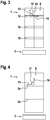
- a seam generating device 3 and an electrically conductive tire component 1 are shown schematically.
- the tire component 1 has reinforcement 12.
- the first electrically conductive element 2a and the second electrically conductive element 2b have been sewn through the tire component 1 in such a way that a sewing direction 13 with a main direction of extent 14 of the reinforcement supports 12 includes an angle 15 of 80 ° to 100 ° and in particular 90 °.
- the surface 8 and the first electrically conductive element 2a are shown.
- the sewing direction 13 is the direction in which the first electrically conductive element 2a and the second electrically conductive element 2b are sewn to one another along the tire component 1.
- a seam generating device 3 and a tire component 1 are shown schematically.
- the tire component 1 is a calendered tire component 1.
- the first electrically conductive element 2 a and the second electrically conductive element 2 b have been sewn through the tire component 1 in such a way that a seam direction 13 forms an angle with a calendering direction 16 of the tire component 1 17 includes from 80 ° to 100 ° and in particular 90 °.
- the surface 8 and the first electrically conductive element 2a are shown.
- the calendering direction 16 of the tire component 1 is the direction in which the tire component 1 is or has been calendered by means of a calender.
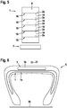
- a seam generating device 3 and a tire component 1 are shown schematically.
- the representation of the Figure 5 shows that the first electrically conductive element 2a and the second electrically conductive Element 2b have been sewn through the tire component 1 in individual rows of seams 18.
- the rows of seams 18 run parallel to one another.
- a distance 19 between the rows of seams 18 is 30 cm to 50 cm.
- the surface 8 and the first electrically conductive element 2a are shown.
- a tire 6 according to the invention is shown schematically in a radial sectional view.
- the tire 6 can be rotated about an axis of rotation 20 in a direction of rotation 21.
- the tire 6 has according to the in FIG Figure 6
- the embodiment shown has two tire components 1 according to the invention, a first tire component 1 being a tire carcass 1a and a second tire component 1 being a tire belt 1b.
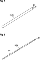
- an electrically conductive element 2a or 2b is shown schematically.
- the electrically conductive element 2a or 2b has a base body 22.
- a coating 23 has been arranged around the base body.
- the base body 22 is formed, for example, from a polyester; the coating 23 is, in particular, a carbon black coating.
- an electrically conductive element 2a or 2b according to a further embodiment is shown schematically.
- a strand 24 has been wound helically around the base body 22.
- the base body 22 has in particular been formed from a polyester.
- the strand 24 is, for example, a carbon strand, a copper strand or a steel strand.
Landscapes
- Engineering & Computer Science (AREA)
- Mechanical Engineering (AREA)
- Textile Engineering (AREA)
- Tyre Moulding (AREA)
- Tires In General (AREA)
Abstract
Description
- Die Erfindung betrifft ein Verfahren zur Herstellung einer elektrisch leitfähigen Reifenkomponente.
- Die Erfindung geht aus von einem Verfahren zur Herstellung einer elektrisch leitfähigen Reifenkomponente, aufweisend die folgenden Schritte:
- Bereitstellen einer Reifenkomponente, wobei die Reifenkomponente aus einer kautschukbasierten Mischung ausgebildet ist;
- Bereitstellen eines ersten elektrisch leitfähigen Elementes und eines zweiten elektrisch leitfähigen Elementes.
- Aus dem Stand der Technik sind Verfahren zur Herstellung elektrisch leitfähiger Reifenkomponenten bekannt. Dabei ist es aus dem Stand der Technik beispielsweise bekannt, elektrisch leitfähige Materialien durch elektrisch nicht leitfähige Reifenkomponenten hindurch zu legen.
Hintergrund ist, dass eine elektrische Leitfähigkeit eines Reifens, der eine an sich elektrisch nicht leitfähige Reifenkomponente aufweist, ermöglicht werden soll. Ziel ist es dabei insbesondere, einen Reifen bereitzustellen, über den elektrische Ströme von einem Fahrzeug auf eine Fahrbahn geleitet werden können. Bei dem Fahrzeug handelt es sich um das Fahrzeug, an dem der Reifen verwendet wird, bei der Fahrbahn handelt es sich um die Fahrbahn, auf der der Reifen rollt. - Bei den aus dem Stand der Technik bekannten Verfahren zur Herstellung einer elektrisch leitfähigen Reifenkomponente könnte die Anordnung der elektrisch leitfähigen Materialien innerhalb der Reifenkomponente mit einem derartigen technischen Aufwand verbunden sein, dass Produktionsabläufe, in deren Rahmen Reifen hergestellt werden sollen, durch das Anordnen der elektrisch leitfähigen Materialien innerhalb der Reifenkomponente verlangsamt werden. Das Verfahren zur Herstellung einer elektrisch leitfähigen Reifenkomponente könnte hinsichtlich seiner Durchführungsgeschwindigkeit nicht optimal ausgestaltet sein. Bei der Durchführungsgeschwindigkeit handelt es sich um die Geschwindigkeit, mit der das Verfahren durchgeführt wird
- Der Erfindung liegt die Aufgabe zugrunde, ein Verfahren zur Herstellung einer elektrisch leitfähigen Reifenkomponente bereitzustellen, dass schneller durchgeführt werden kann, als die aus dem Stand der Technik bekannten Verfahren.
- Gelöst wird die gestellte Aufgabe dadurch, dass das Verfahren zur Herstellung einer elektrisch leitfähigen Reifenkomponente durch die weiteren Schritte wie folgt gekennzeichnet ist:
- Bereitstellen einer Nahterzeugungsvorrichtung, wobei die Nahterzeugungsvorrichtung dazu vorgesehen ist, das erste elektrisch leitfähige Element und das zweite elektrisch leitfähige Element in die Reifenkomponente einzunähen und dabei das erste elektrisch leitfähige Element mit dem zweiten elektrisch leitfähigen Element derart zu vernähen, dass das erste elektrisch leitfähige Element in Kontakt mit dem zweiten elektrisch leitfähigen Element steht;
- Einnähen des ersten elektrisch leitfähigen Elementes und des zweiten elektrisch leitfähigen Elementes in die Reifenkomponente mittels der Nahterzeugungsvorrichtung, wobei durch das Einnähen Bereiche des ersten elektrisch leitfähigen Elementes auf ersten Oberflächenbereichen einer ersten Oberfläche der Reifenkomponente angeordnet werden und Bereiche des zweiten elektrisch leitfähigen Elementes auf zweiten Oberflächenbereichen einer zweiten Oberfläche der Reifenkomponente angeordnet werden, derart, dass die Bereiche des ersten elektrisch leitfähigen Elementes und des zweiten elektrisch leitfähigen Elementes elektrisch leitfähig miteinander verbunden sind.
- Durch den erfindungsgemäßen Umstand, wonach das Verfahren durch diese weiteren Schritte gekennzeichnet ist, wird ein Verfahren zur Herstellung einer elektrisch leitfähigen Reifenkomponente ermöglicht und bereitgestellt, mittels dem auf raschere Art eine elektrisch leitfähige Reifenkomponente hergestellt werden kann, als es bei aus dem Stand der Technik bekannten Verfahren der Fall ist. Hintergrund ist, dass mittels dieses Verfahrens des Einnähens mittels der Nahterzeugungsvorrichtung ein elektrisch leitfähiges Element mit einem anderen elektrisch leitfähigen Element derart automatisiert und rasch in einer Reifenkomponente vernäht und verbunden werden kann, dass eine elektrisch leitfähige Verbindung durch die Reifenkomponente hindurch ermöglicht wird. Die elektrische Leitfähigkeit der Reifenkomponente ist nach Anwendung des Einnähverfahrens und dadurch, dass das erste elektrisch leitfähige Element mit dem zweiten elektrisch leitfähigen Element in Kontakt gebracht wird, sichergestellt. Durch den Umstand, dass das das erste elektrisch leitfähige Element mit dem zweiten elektrisch leitfähigen Element in Kontakt gebracht wird, wird eine elektrische Kopplung des ersten elektrisch leitfähigen Elementes mit dem zweiten elektrisch leitfähigen Element bewirkt.
- Somit wird ein verbessertes Verfahren zur Herstellung einer elektrisch leitfähigen Reifenkomponente bereitgestellt.
- Die Erfindung betrifft ferner eine Reifenkomponente, die nach einem erfindungsgemäßen Verfahren hergestellt worden ist.
- Die Erfindung betrifft ferner einen Reifen, aufweisend mindestens eine erfindungsgemäße Reifenkomponente.
- Bei dem Reifen handelt es sich beispielsweise um einen PKW-Reifen, um einen LKW-Reifen oder um einen Zweirad-Reifen.
- Weitere vorteilhafte Ausgestaltungsformen der vorliegenden Erfindung sind Gegenstand der Unteransprüche.
- Gemäß einer nächsten vorzugsweisen Ausgestaltungsform des erfindungsgemäßen Verfahrens handelt es sich bei dem ersten elektrisch leitfähigen Element und dem zweiten elektrisch leitfähigen Element um ein Garn oder um einen Draht.
Bei dem Garn oder dem Draht handelt es sich beispielsweise um ein Stahlgarn oder ein Kupfergarn beziehungsweise um einen Stahldraht oder einen Kupferdraht. - Durch den erfindungsgemäßen Umstand, wonach es sich bei dem ersten elektrisch leitfähigen Element und dem zweiten elektrisch leitfähigen Element um ein Garn oder um einen Draht handelt, werden elektrisch leitfähige Elemente bereitgestellt, die zuverlässig und aufwandsarm mittels der Nahterzeugungsvorrichtung in der Reifenkomponente vernäht und miteinander in Kontakt gebracht werden können.
- Gemäß einer nächsten vorzugsweisen Ausgestaltungsform des erfindungsgemäßen Verfahrens sind das erste elektrisch leitfähige Element und das zweite elektrisch leitfähige Element jeweils aus einem Polyester ausgebildet, wobei das Polyester eine Rußbeschichtung aufweist oder das Polyester mit einer Karbon-Litze umwickelt worden ist oder das Polyester mit einer Kupfer-Litze umwickelt worden ist oder das Polyester mit einer Stahl-Litze umwickelt worden ist.
- Durch den erfindungsgemäßen Umstand, wonach das erste elektrisch leitfähige Element und das zweite elektrisch leitfähige Element jeweils aus einem Polyester ausgebildet sind, wobei das Polyester eine Rußbeschichtung aufweist oder das Polyester mit einer Karbon-Litze umwickelt worden ist oder das Polyester mit einer Kupfer-Litze umwickelt worden ist oder das Polyester mit einer Stahl-Litze umwickelt worden ist, werden elektrisch leitfähige Materialien verwendet, die den mechanischen Belastungen, die während eines regulären Betriebs des Reifens auftreten können, standhalten können und die zugleich eine ausreichende elektrische Leitfähigkeit aufweisen.
- Hintergrund des Umstands, dass die elektrisch leitfähigen Elemente den mechanischen Belastungen standhalten können, sind die mechanischen und chemischen Eigenschaften des Polyesters.
Hintergrund der ausreichenden elektrischen Leitfähigkeit sind die physikalischen Eigenschaften der Rußbeschichtung, der Karbon-Litze, der Kupfer-Litze und der Stahl-Litze.
Sowohl eine Rußbeschichtung, als auch Karbon, Kupfer oder Stahl besitzen eine ausreichende elektrische Leitfähigkeit. Ausreichend ist die elektrische Leitfähigkeit insbesondere dann, wenn elektrische Ströme, die in einem Fahrzeug, an dem die erfindungsgemäße Reifenkomponente verwendet wird, auftreten über die Reifenkomponente zu einer Fahrbahn abgeleitet werden können. - Gemäß einer nächsten vorzugsweisen Ausgestaltungsform der vorliegenden Erfindung werden das erste elektrisch leitfähige Element und das zweite elektrisch leitfähige Element jeweils in einem Stichabstand von 3 cm bis 10 cm in die Reifenkomponente eingenäht.
- Durch den erfindungsgemäßen Umstand, wonach das erste elektrisch leitfähige Element und das zweite elektrisch leitfähige Element jeweils in einem Stichabstand von 3 cm bis 10 cm in die Reifenkomponente eingenäht werden, können das erste elektrisch leitfähige Element und das zweite elektrisch leitfähige Element miteinander vernäht werden. Zugleich wird die Reifenkomponente aufgrund des Stichabstandes von 3 cm bis 10 cm in einem vertretbaren Maß durch den Nähvorgang belastet.
- Während des Nähvorgangs bewegt sich die Nahterzeugungsvorrichtung relativ zu der Reifenkomponente. Die Bewegung ist dabei gleichförmig. Der Stichabstand ist dann ein Abstand in eine Richtung parallel zu dieser relativen Bewegung der Nahterzeugungsvorrichtung zu der Reifenkomponente.
- Gemäß einer nächsten vorzugsweisen Ausgestaltungsform der vorliegenden Erfindung werden das erste elektrisch leitfähige Element und das zweite elektrisch leitfähige Element derart durch die Reifenkomponente genäht, dass durch das Einnähen Bereiche des ersten elektrisch leitfähigen Elements auf Oberflächenbereichen der ersten Oberfläche der Reifenkomponente angeordnet werden und Bereiche des zweiten elektrisch leitfähigen Elementes auf Oberflächenbereichen der zweiten Oberfläche der Reifenkomponente angeordnet werden. Ein Normalvektor der ersten Oberfläche und ein Normalvektor der zweiten Oberfläche weisen in entgegengesetzte Richtungen.
- Gemäß einer nächsten vorzugsweisen Ausgestaltungsform des vorliegenden Verfahrens werden für den Fall, wonach die Reifenkomponente Festigkeitsträger aufweist, das erste elektrisch leitfähige Element und das zweite elektrisch leitfähige Element derart durch die Reifenkomponente genäht, dass eine Nahtrichtung mit einer Haupterstreckungsrichtung der Festigkeitsträger einen Winkel von 80° bis 100° und insbesondere 90° einschließt.
- Bei den Festigkeitsträgern kann es sich um Festigkeitsträger eines Reifengürtels oder einer Reifenkarkasse handeln. Bei der Nahtrichtung handelt es sich um eine Richtung, die parallel zu der Richtung verläuft, in die die Relativbewegung der Nahterzeugungsvorrichtung und der Reifenkomponente weist.
- Durch den erfindungsgemäßen Umstand, wonach für den Fall, wonach die Reifenkomponente Festigkeitsträger aufweist, das erste elektrisch leitfähige Element und das zweite elektrisch leitfähige Element derart durch die Reifenkomponente genäht werden, dass eine Nahtrichtung mit einer Haupterstreckungsvorrichtung der Festigkeitsträger einen Winkel von 80° bis 100° und insbesondere 90° einschließt, können das erste elektrisch leitfähige Element und das zweite elektrisch leitfähige Element derart an oder in der Reifenkomponente angeordnet werden, dass eine vorteilhafte Wechselwirkung mit den Festigkeitsträgern ermöglicht wird.
- Gemäß einer nächsten vorzugsweisen Ausgestaltungsform des erfindungsgemäßen Verfahrens werden für den Fall, wonach die Reifenkomponente kalandriert wird oder kalandriert worden ist, das erste elektrisch leitfähige Element und das zweite elektrisch leitfähige Element derart durch die Reifenkomponente genäht, dass eine Nahtrichtung mit einer Kalandrierrichtung der Reifenkomponente einen Winkel von 80° bis 100° und insbesondere 90° einschließt.
- Bei einer Kalandrierrichtung handelt es sich um die Richtung, in die eine Reifenkomponente durch einen Kalander hindurch kalandriert wird oder kalandriert worden ist.
- Durch den erfindungsgemäßen Umstand, wonach für den Fall, wonach die Reifenkomponente kalandriert wird oder kalandriert worden ist, das erste elektrisch leitfähigen Element und das zweite elektrisch leitfähige Element derart durch die Reifenkomponente genäht werden, dass eine Nahtrichtung mit einer Kalandrierrichtung der Reifenkomponente einen Winkel von 80° bis 100° und insbesondere 90° einschließt, können das erste elektrisch leitfähige Element und das zweite elektrisch leitfähige Element derart an oder in der Reifenkomponente angeordnet werden, dass eine vorteilhafte Wechselwirkung mit beispielsweise bereits an der Reifenkomponente angeordneten elektrisch leitfähigen Elementen oder bereits an der Reifenkomponente angeordneten elektrisch leitfähigen Komponenten ermöglicht wird.
- Gemäß einer nächsten vorzugsweisen Ausgestaltungsform des erfindungsgemäßen Verfahrens werden das erste elektrisch leitfähige Element und das zweite elektrisch leitfähige Element in einzelnen Nahtreihen durch die Reifenkomponente genäht, wobei die Nahtreihen parallel zueinander verlaufen und einen Abstand voneinander aufweisen, wobei der Abstand insbesondere 30 cm bis 50 cm beträgt.
- Gemäß einer nächsten vorzugsweisen Ausgestaltungsform des erfindungsgemäßen Verfahrens handelt es sich bei der Reifenkomponente um eine Reifenkarkasse oder um einen Reifengürtel.
- Weitere Merkmale, Vorteile und Einzelheiten, auf die die Erfindung in ihrem Umfang aber nicht beschränkt ist, werden nun anhand der Zeichnungen näher beschrieben.
- Es zeigt:
-
Fig. 1 : Eine schematische Darstellung einer erfindungsgemäßen Nahterzeugungsvorrichtung zur Durchführung eines erfindungsgemäßen Verfahrens und einer Reifenkomponente; -
Fig. 2 : eine schematische Darstellung einer erfindungsgemäßen Nahterzeugungsvorrichtung zur Durchführung eines erfindungsgemäßen Verfahrens und einer Reifenkomponente; -
Fig. 3 : eine schematische Darstellung einer erfindungsgemäßen Nahterzeugungsvorrichtung zur Durchführung eines erfindungsgemäßen Verfahrens und einer Reifenkomponente gemäß einer weiteren Ausführungsform; -
Fig. 4 : eine schematische Darstellung einer erfindungsgemäßen Nahterzeugungsvorrichtung zur Durchführung eines erfindungsgemäßen Verfahrens und einer Reifenkomponente gemäß einer weiteren Ausführungsform; -
Fig. 5 : eine schematische Darstellung einer Nahterzeugungskomponente zur Durchführung eines erfindungsgemäßen Verfahrens und einer Reifenkomponente gemäß einer weiteren Ausführungsform; -
Fig. 6 : eine schematische Darstellung eines erfindungsgemäßen Reifens; -
Fig. 7 : eine schematische Darstellung eines elektrisch leitfähigen Elementes; -
Fig. 8 : eine schematische Darstellung eines elektrisch leitfähigen Elementes gemäß einer Ausführungsform. - In der
Figur 1 ist eine Nahterzeugungsvorrichtung 3 zur Anwendung in einem erfindungsgemäßen Verfahren schematisch dargestellt. In derFigur 1 ist ferner eine Reifenkomponente 1 dargestellt. Die Reifenkomponente 1 ist aus einer kautschukbasierten Mischung ausgebildet. - Die Nahterzeugungsvorrichtung 3 ist dazu vorgesehen, ein erstes elektrisch leitfähiges Element 2a und ein zweites elektrisch leitfähiges Element 2b in die Reifenkomponente 1 einzunähen. Dabei ist die Nahterzeugungsvorrichtung 3 ferner dazu vorgesehen, das erste elektrisch leitfähige Element 2a mit dem zweiten elektrisch leitfähigen Element 2b derart zu vernähen, dass das erste elektrisch leitfähige Element 2a in Kontakt mit dem zweiten elektrisch leitfähigen Element 2b steht. Dabei werden das erste elektrisch leitfähige Element 2a und das zweite elektrisch leitfähige Element 2b mittels der Nahterzeugungsvorrichtung 3 in die Reifenkomponente 1 vernäht, wobei durch das Einnähen Bereiche 4a des ersten elektrisch leitfähigen Elementes 2a auf ersten Oberflächenbereichen 5a einer ersten Oberfläche 8 der Reifenkomponente 1 angeordnet werden und Bereiche 4b des zweiten elektrisch leitfähigen Elementes 2b auf zweiten Oberflächenbereichen 5b einer zweiten Oberfläche 9 der Reifenkomponente 1 derart angeordnet werden, dass die Bereiche 4a, 4b des ersten elektrisch leitfähigen Elementes 2a und des zweiten elektrisch leitfähigen Elementes 2b elektrisch leitfähig miteinander verbunden sind.
- Gemäß der in der
Figur 1 schematisch dargestellten Ausführungsform weisen ein Normalvektor 10 der ersten Oberfläche 8 und ein Normalvektor 11 der zweiten Oberfläche 9 in zueinander entgegengesetzte Richtungen. - In der
Figur 2 ist eine Nahterzeugungsvorrichtung 3 zur Durchführung eines erfindungsgemäßen Verfahrens und eine Reifenkomponente 1 gemäß einer weiteren Ausführungsform schematisch dargestellt. Gemäß der Darstellung in derFigur 2 sind das erste elektrische leitfähige Element 2a und das zweite elektrisch leitfähige Element 2b jeweils in einem Stichabstand 7 von 3 cm bis 10 cm in die Reifenkomponente 1 eingenäht worden. - In der
Figur 3 sind eine Nahterzeugungsvorrichtung 3 und eine elektrisch leitfähige Reifenkomponente 1 gemäß einer weiteren Ausführungsform schematisch dargestellt. Gemäß der Darstellung in derFigur 3 weist die Reifenkomponente 1 Festigkeitsträger 12 auf. Das erste elektrisch leitfähige Element 2a und das zweite elektrisch leitfähige Element 2b sind derart durch die Reifenkomponente 1 genäht worden, dass eine Nahtrichtung 13 mit einer Haupterstreckungsrichtung 14 der Festigkeitsträger 12 einen Winkel 15 von 80° bis 100° und insbesondere 90° einschließt. Gemäß der Darstellung in derFigur 3 sind die Oberfläche 8 und das erste elektrisch leitfähige Element 2a dargestellt. Die Nahtrichtung 13 ist die Richtung, in die das erste elektrisch leitfähige Element 2a und das zweite elektrisch leitfähige Element 2b entlang der Reifenkomponente 1 miteinander vernäht werden. - In der
Figur 4 sind eine Nahterzeugungsvorrichtung 3 und eine Reifenkomponente 1 gemäß einer weiteren Ausführungsform schematisch dargestellt. Gemäß der Darstellung in derFigur 4 handelt es sich bei der Reifenkomponente 1 um eine kalandrierte Reifenkomponente 1. Das erste elektrisch leitfähige Element 2 a und das zweite elektrisch leitfähige Element 2 b sind derart durch die Reifenkomponente 1 genäht worden, dass eine Nahtrichtung 13 mit einer Kalandrierrichtung 16 der Reifenkomponente 1 einen Winkel 17 von 80° bis 100° und insbesondere 90° einschließt.
Gemäß der Darstellung in derFigur 4 sind die Oberfläche 8 und das erste elektrisch leitfähige Element 2a dargestellt.
Die Kalandrierrichtung 16 der Reifenkomponente 1 ist die Richtung, in die die Reifenkomponente 1 mittels eines Kalanders kalandriert wird oder kalandriert worden ist. - In der
Figur 5 sind eine Nahterzeugungsvorrichtung 3 und eine Reifenkomponente 1 gemäß einer weiteren Ausführungsform schematisch dargestellt. Die Darstellung derFigur 5 zeigt, dass das erste elektrisch leitfähige Element 2a und das zweite elektrisch leitfähige Element 2b in einzelnen Nahtreihen 18 durch die Reifenkomponente 1 genäht worden sind. Die Nahtreihen 18 verlaufen parallel zueinander. Ein Abstand 19 der Nahtreihen 18 voneinander beträgt 30 cm bis 50 cm.
Gemäß der Darstellung in derFigur 5 sind die Oberfläche 8 und das erste elektrisch leitfähige Element 2a dargestellt. - In der
Figur 6 ist ein erfindungsgemäßer Reifen 6 schematisch in Radialschnittansicht dargestellt. Der Reifen 6 ist um eine Rotationsachse 20 in eine Umlaufrichtung 21 rotierbar. Der Reifen 6 weist gemäß der in derFigur 6 dargestellten Ausführungsform zwei erfindungsgemäße Reifenkomponenten 1 auf, wobei es sich bei einer ersten Reifenkomponente 1 um eine Reifenkarkasse 1a und bei einer zweiten Reifenkomponente 1 um einen Reifengürtel 1b handelt. - In der
Figur 7 ist ein elektrisch leitfähiges Element 2a oder 2b schematisch dargestellt. Gemäß der Darstellung in derFigur 7 weist das elektrisch leitfähige Element 2a oder 2b einen Grundkörper 22 auf. Wobei um den Grundkörper eine Beschichtung 23 angeordnet worden ist. Der Grundkörper 22 ist beispielsweise aus einem Polyester ausgebildet, bei der Beschichtung 23 handelt es sich insbesondere um eine Rußbeschichtung. - In der
Figur 8 ist ein elektrisch leitfähiges Element 2a oder 2b gemäß einer weiteren Ausführungsform schematisch dargestellt. Gemäß der Darstellung in derFigur 8 ist um den Grundkörper 22 herum eine Litze 24 wendelförmig gewickelt worden. Der Grundkörper 22 ist insbesondere aus einem Polyester ausgebildet worden. Bei der Litze 24 handelt es sich beispielsweise um eine Karbon-Litze, um eine Kupfer-Litze oder um eine Stahl-Litze. -
- 1
- Reifenkomponente
- 1a
- Reifenkarkasse
- 1b
- Reifengürtel
- 2a
- erstes elektrisch leitfähiges Element
- 2b
- zweites elektrisch leitfähiges Element
- 3
- Nahterzeugungsvorrichtung
- 4a
- Bereiche des ersten elektrisch leitfähigen Elementes
- 4b
- Bereiche des zweiten elektrisch leitfähigen Elementes
- 5a
- erste Oberflächenbereiche der Reifenkomponente
- 5b
- zweite Oberflächenbereiche der Reifenkomponente
- 6
- Reifen
- 7
- Stichabstand
- 8
- erste Oberfläche der Reifenkomponente
- 9
- zweite Oberfläche der Reifenkomponente
- 10
- Normalvektor der ersten Oberfläche der Reifenkomponente
- 11
- Normalvektor der zweiten Oberfläche der Reifenkomponente
- 12
- Festigkeitsträger
- 13
- Nahtrichtung
- 14
- Haupterstreckungsrichtung der Festigkeitsträger
- 15
- Winkel
- 16
- Kalandrierrichtung
- 17
- Winkel
- 18
- Nahtreihen
- 19
- Abstand
- 20
- Rotationsachse
- 21
- Umlaufrichtung
- 22
- Grundkörper
- 23
- Beschichtung
- 24
- Litze
Claims (11)
- Verfahren zur Herstellung einer elektrisch leitfähigen Reifenkomponente (1), aufweisend die folgenden Schritte:- Bereitstellen einer Reifenkomponente (1), wobei die Reifenkomponente (1) aus einer kautschukbasierten Mischung ausgebildet ist;- Bereitstellen eines ersten elektrisch leitfähigen Elementes (2a) und eines zweiten elektrisch leitfähigen Elementes (2b);- Bereitstellen einer Nahterzeugungsvorrichtung (3), wobei die Nahterzeugungsvorrichtung (3) dazu vorgesehen ist, das erste elektrisch leitfähige Element (2a) und das zweite elektrisch leitfähige Element (2b) in die Reifenkomponente (1) einzunähen und dabei das erste elektrisch leitfähige Element (2a) mit dem zweiten elektrisch leitfähigen Element (2b) derart zu vernähen, dass das erste elektrisch leitfähige Element (2a) in Kontakt mit dem zweiten elektrisch leitfähigen Element (2b) steht;- Einnähen des ersten elektrisch leitfähigen Elementes (2a) und des zweiten elektrisch leitfähigen Elementes (2b) in die Reifenkomponente (1) mittels der Nahterzeugungsvorrichtung (3), wobei durch das Einnähen Bereiche (4a) des ersten elektrisch leitfähigen Elementes (2a) auf ersten Oberflächenbereichen (5a) der Reifenkomponente (1) angeordnet werden und Bereiche (4b) des zweiten elektrisch leitfähigen Elementes (2b) auf zweiten Oberflächenbereichen (5b) der Reifenkomponente (1) angeordnet werden, derart, dass die Bereiche (4a, 4b) elektrisch leitfähig miteinander verbunden sind.
- Verfahren nach Anspruch 1, dadurch gekennzeichnet, dass es sich es sich bei dem ersten elektrisch leitfähigen Element (2a) und dem zweiten elektrisch leitfähigen Element (2b) um ein Garn oder um einen Draht handelt.
- Verfahren nach Anspruch 1 oder Anspruch 2, dadurch gekennzeichnet, dass das erste elektrisch leitfähige Element (2a) und das zweite elektrisch leitfähige Element (2b) jeweils aus einem Polyester (22) ausgebildet sind, wobei das Polyester (22) eine Rußbeschichtung (23) aufweist oder das Polyester (22) mit einer Karbon-Litze (24) umwickelt worden ist oder das Polyester (22) mit einer Kupfer-Litze (24) umwickelt worden ist oder das Polyester (22) mit einer Stahl-Litze (24) umwickelt worden ist.
- Verfahren nach einem der vorhergehenden Ansprüche, dadurch gekennzeichnet, dass das erste elektrisch leitfähige Element (2a) und das zweite elektrisch leitfähige Element (2b) jeweils in einem Stichabstand (7) von 3 cm bis 10 cm in die Reifenkomponente (1) eingenäht werden.
- Verfahren nach einem der vorhergehenden Ansprüche, dadurch gekennzeichnet, dass das erste elektrisch leitfähige Element (2a) und das zweite elektrisch leitfähige Element (2b) derart durch die Reifenkomponente (1) genäht werden, dass durch das Einnähen Bereiche (4a) des ersten elektrisch leitfähigen Elementes (2a) auf Oberflächenbereichen (5a, 5b) einer ersten Oberfläche (8) der Reifenkomponente (1) angeordnet werden und Bereiche (4b) des zweiten elektrisch leitfähigen Elementes (2b) auf Oberflächenbereichen (5) einer zweiten Oberfläche (9) der Reifenkomponente (1) angeordnet werden, wobei ein Normalvektor (10) der ersten Oberfläche (8) und ein Normalvektor (11) der zweiten Oberfläche (9) in entgegengesetzte Richtungen weisen.
- Verfahren nach einem der vorhergehenden Ansprüche, dadurch gekennzeichnet, dass für den Fall, wonach die Reifenkomponente (1) Festigkeitsträger (12) aufweist, das erste elektrisch leitfähige Element (2a) und das zweite elektrisch leitfähige Elemente (2b) derart durch die Reifenkomponente (1) genäht werden, dass eine Nahtrichtung (13) mit einer Haupterstreckungsrichtung (14) der Festigkeitsträger (12) einen Winkel (15) von 80° bis 100° und insbesondere 90° einschließt.
- Verfahren nach einem der vorhergehenden Ansprüche, dadurch gekennzeichnet, dass das für den Fall, wonach die Reifenkomponente (1) kalandriert wird oder kalandriert worden ist, das erste elektrisch leitfähige Element (2a) und das zweite elektrisch leitfähige Element (2b) derart durch die Reifenkomponente (1) genäht werden, dass eine Nahtrichtung (13) mit einer Kalandrierrichtung (16) der Reifenkomponente (1) einen Winkel (17) von 80° bis 100° und insbesondere 90° einschließt.
- Verfahren nach einem der vorhergehenden Ansprüche, dadurch gekennzeichnet, dass das erste elektrisch leitfähige Element (2a) und das zweite elektrisch leitfähige Element (2b) in einzelnen Nahtreihen (18) durch die Reifenkomponente (1) genäht werden, wobei die Nahtreihen (18) parallel zu einander verlaufen und einen Abstand (19) voneinander aufweisen, wobei der Abstand (19) insbesondere 30 cm bis 50 cm beträgt.
- Verfahren nach einem der vorhergehenden Ansprüche, dadurch gekennzeichnet, dass es sich bei der Reifenkomponente (1) um eine Reifenkarkasse (1a) oder um einen Reifengürtel (1b) handelt.
- Reifenkomponente (1, 1a, 1b), hergestellt nach einem der Verfahren der vorhergehenden Ansprüche.
- Reifen (6), aufweisend mindestens eine Reifenkomponente (1, 1a, 1b) nach dem vorhergehenden Anspruch.
Applications Claiming Priority (1)
| Application Number | Priority Date | Filing Date | Title |
|---|---|---|---|
| DE102020202898.2A DE102020202898A1 (de) | 2020-03-06 | 2020-03-06 | Verfahren zur Herstellung einer Reifenkomponente |
Publications (2)
| Publication Number | Publication Date |
|---|---|
| EP3875261A1 true EP3875261A1 (de) | 2021-09-08 |
| EP3875261B1 EP3875261B1 (de) | 2024-10-16 |
Family
ID=73838882
Family Applications (1)
| Application Number | Title | Priority Date | Filing Date |
|---|---|---|---|
| EP20213648.7A Active EP3875261B1 (de) | 2020-03-06 | 2020-12-14 | Verfahren zur herstellung einer elektrisch leitfähigen reifenkomponente und reifenkomponente |
Country Status (2)
| Country | Link |
|---|---|
| EP (1) | EP3875261B1 (de) |
| DE (1) | DE102020202898A1 (de) |
Citations (7)
| Publication number | Priority date | Publication date | Assignee | Title |
|---|---|---|---|---|
| EP0655321A2 (de) * | 1993-11-30 | 1995-05-31 | Sumitomo Rubber Industries Ltd. | Reifengewebe für Kautschukverstärkung, Kordeinlage für Reifenverstärkung und Verfahren zur Herstellung eines Reifengewebes für Kautschukverstärkung |
| DE102006036406A1 (de) * | 2006-01-27 | 2007-08-09 | W. Zimmermann Gmbh & Co. Kg | Elektrisch leitfähiges Textil |
| DE102010037328A1 (de) * | 2010-09-06 | 2012-03-08 | Continental Reifen Deutschland Gmbh | Fahrzeugluftreifen |
| EP3088215A1 (de) * | 2013-12-26 | 2016-11-02 | The Yokohama Rubber Co., Ltd. | Luftreifen |
| WO2017088994A1 (de) * | 2015-11-26 | 2017-06-01 | Continental Reifen Deutschland Gmbh | Fahrzeugluftreifen |
| US20170197480A1 (en) * | 2016-01-13 | 2017-07-13 | Bridgestone Corporation | Pneumatic tire |
| EP3489042A1 (de) * | 2017-11-28 | 2019-05-29 | Kumho Tire Co., Inc. | Luftreifen |
-
2020
- 2020-03-06 DE DE102020202898.2A patent/DE102020202898A1/de active Pending
- 2020-12-14 EP EP20213648.7A patent/EP3875261B1/de active Active
Patent Citations (7)
| Publication number | Priority date | Publication date | Assignee | Title |
|---|---|---|---|---|
| EP0655321A2 (de) * | 1993-11-30 | 1995-05-31 | Sumitomo Rubber Industries Ltd. | Reifengewebe für Kautschukverstärkung, Kordeinlage für Reifenverstärkung und Verfahren zur Herstellung eines Reifengewebes für Kautschukverstärkung |
| DE102006036406A1 (de) * | 2006-01-27 | 2007-08-09 | W. Zimmermann Gmbh & Co. Kg | Elektrisch leitfähiges Textil |
| DE102010037328A1 (de) * | 2010-09-06 | 2012-03-08 | Continental Reifen Deutschland Gmbh | Fahrzeugluftreifen |
| EP3088215A1 (de) * | 2013-12-26 | 2016-11-02 | The Yokohama Rubber Co., Ltd. | Luftreifen |
| WO2017088994A1 (de) * | 2015-11-26 | 2017-06-01 | Continental Reifen Deutschland Gmbh | Fahrzeugluftreifen |
| US20170197480A1 (en) * | 2016-01-13 | 2017-07-13 | Bridgestone Corporation | Pneumatic tire |
| EP3489042A1 (de) * | 2017-11-28 | 2019-05-29 | Kumho Tire Co., Inc. | Luftreifen |
Also Published As
| Publication number | Publication date |
|---|---|
| EP3875261B1 (de) | 2024-10-16 |
| DE102020202898A1 (de) | 2021-09-09 |
Similar Documents
| Publication | Publication Date | Title |
|---|---|---|
| DE60115706T2 (de) | Stahlseil zur verstärkung von geländereifen und förderbändern | |
| DE69219805T2 (de) | Metallkorde zur Verstärkung von Gummi und Luftreifen mit solchen Verstärkungen | |
| DE69421090T2 (de) | Offene stahlkordkonstruktion | |
| EP1097094B1 (de) | Fördergurt mit trägergewebe, in den leiterschleifen eingebettet sind | |
| DE602004013324T2 (de) | Hybridkord hoher dehnung | |
| DE69318582T2 (de) | Stahlseil | |
| DE69709379T2 (de) | Luftreifen | |
| DE102019128172A1 (de) | Integrierter multipol-steckverbinder | |
| DE102012002218A1 (de) | Geschirmtes Kabel und Vorrichtung zum Herstellen eines derartigen Kabels | |
| DE1680467A1 (de) | Laufflaechenring fuer Reifen mit abnehmbarem Laufflaechenteil | |
| DE102020202965A1 (de) | Batteriegehäuse mit mindestens zwei, miteinander verbundenen Gehäuseelementen sowie Verfahren zur Herstellung einer Verbindung von mindestens zwei Gehäuseelementen zu einem Batteriegehäuse | |
| DE102018214554A1 (de) | Dichtigkeitsprüfung von Kraftfahrzeugkarosserien | |
| DE102020104510A1 (de) | Ladebuchse für ein Elektrofahrzeug | |
| EP3875261B1 (de) | Verfahren zur herstellung einer elektrisch leitfähigen reifenkomponente und reifenkomponente | |
| DE69609041T2 (de) | Stahlseile zur Verstärkung von Gummiartikeln und solche Stahlseile aufweisender radialer Luftreifen | |
| DE69915750T2 (de) | Stahlkord zur Verstärkung eines Radialreifens und Radialreifen mit demselben | |
| DE2364966A1 (de) | Verfahren zum verbinden von draehten, litzen und seilen | |
| DE112024001258T5 (de) | Stahlcord, Cord-Gummi-Verbundwerkstoff und Reifen | |
| EP3872937A1 (de) | Elektrischer steckverbinder und verfahren zur herstellung eines elektrischen steckverbinders | |
| DE102020200523A1 (de) | Fahrzeugreifen | |
| DE112014003816T5 (de) | Luftreifen und Verfahren zum Herstellen eines Luftreifens | |
| DE112017001076B4 (de) | Faserverstärkter Harzhohlkörper | |
| DE102021105331A1 (de) | Elastisches Getriebeelement, Untersetzungsgetriebe und Fehlererkennungsverfahren für das Untersetzungsgetriebe | |
| DE102015118779A1 (de) | Elektrischer Kontakt | |
| EP2960990B1 (de) | Anordnung zur elektromagnetischen Abschirmung |
Legal Events
| Date | Code | Title | Description |
|---|---|---|---|
| PUAI | Public reference made under article 153(3) epc to a published international application that has entered the european phase |
Free format text: ORIGINAL CODE: 0009012 |
|
| STAA | Information on the status of an ep patent application or granted ep patent |
Free format text: STATUS: THE APPLICATION HAS BEEN PUBLISHED |
|
| AK | Designated contracting states |
Kind code of ref document: A1 Designated state(s): AL AT BE BG CH CY CZ DE DK EE ES FI FR GB GR HR HU IE IS IT LI LT LU LV MC MK MT NL NO PL PT RO RS SE SI SK SM TR |
|
| STAA | Information on the status of an ep patent application or granted ep patent |
Free format text: STATUS: REQUEST FOR EXAMINATION WAS MADE |
|
| 17P | Request for examination filed |
Effective date: 20220309 |
|
| RBV | Designated contracting states (corrected) |
Designated state(s): AL AT BE BG CH CY CZ DE DK EE ES FI FR GB GR HR HU IE IS IT LI LT LU LV MC MK MT NL NO PL PT RO RS SE SI SK SM TR |
|
| STAA | Information on the status of an ep patent application or granted ep patent |
Free format text: STATUS: EXAMINATION IS IN PROGRESS |
|
| 17Q | First examination report despatched |
Effective date: 20230418 |
|
| RAP3 | Party data changed (applicant data changed or rights of an application transferred) |
Owner name: CONTINENTAL REIFEN DEUTSCHLAND GMBH |
|
| GRAP | Despatch of communication of intention to grant a patent |
Free format text: ORIGINAL CODE: EPIDOSNIGR1 |
|
| STAA | Information on the status of an ep patent application or granted ep patent |
Free format text: STATUS: GRANT OF PATENT IS INTENDED |
|
| INTG | Intention to grant announced |
Effective date: 20240618 |
|
| P01 | Opt-out of the competence of the unified patent court (upc) registered |
Free format text: CASE NUMBER: APP_43043/2024 Effective date: 20240723 |
|
| GRAS | Grant fee paid |
Free format text: ORIGINAL CODE: EPIDOSNIGR3 |
|
| GRAA | (expected) grant |
Free format text: ORIGINAL CODE: 0009210 |
|
| STAA | Information on the status of an ep patent application or granted ep patent |
Free format text: STATUS: THE PATENT HAS BEEN GRANTED |
|
| AK | Designated contracting states |
Kind code of ref document: B1 Designated state(s): AL AT BE BG CH CY CZ DE DK EE ES FI FR GB GR HR HU IE IS IT LI LT LU LV MC MK MT NL NO PL PT RO RS SE SI SK SM TR |
|
| REG | Reference to a national code |
Ref country code: GB Ref legal event code: FG4D Free format text: NOT ENGLISH |
|
| REG | Reference to a national code |
Ref country code: CH Ref legal event code: EP |
|
| REG | Reference to a national code |
Ref country code: IE Ref legal event code: FG4D Free format text: LANGUAGE OF EP DOCUMENT: GERMAN |
|
| REG | Reference to a national code |
Ref country code: DE Ref legal event code: R096 Ref document number: 502020009490 Country of ref document: DE |
|
| REG | Reference to a national code |
Ref country code: LT Ref legal event code: MG9D |
|
| REG | Reference to a national code |
Ref country code: NL Ref legal event code: MP Effective date: 20241016 |
|
| PG25 | Lapsed in a contracting state [announced via postgrant information from national office to epo] |
Ref country code: NL Free format text: LAPSE BECAUSE OF FAILURE TO SUBMIT A TRANSLATION OF THE DESCRIPTION OR TO PAY THE FEE WITHIN THE PRESCRIBED TIME-LIMIT Effective date: 20241016 |
|
| PG25 | Lapsed in a contracting state [announced via postgrant information from national office to epo] |
Ref country code: NL Free format text: LAPSE BECAUSE OF FAILURE TO SUBMIT A TRANSLATION OF THE DESCRIPTION OR TO PAY THE FEE WITHIN THE PRESCRIBED TIME-LIMIT Effective date: 20241016 |
|
| PG25 | Lapsed in a contracting state [announced via postgrant information from national office to epo] |
Ref country code: PT Free format text: LAPSE BECAUSE OF FAILURE TO SUBMIT A TRANSLATION OF THE DESCRIPTION OR TO PAY THE FEE WITHIN THE PRESCRIBED TIME-LIMIT Effective date: 20250217 Ref country code: IS Free format text: LAPSE BECAUSE OF FAILURE TO SUBMIT A TRANSLATION OF THE DESCRIPTION OR TO PAY THE FEE WITHIN THE PRESCRIBED TIME-LIMIT Effective date: 20250216 Ref country code: HR Free format text: LAPSE BECAUSE OF FAILURE TO SUBMIT A TRANSLATION OF THE DESCRIPTION OR TO PAY THE FEE WITHIN THE PRESCRIBED TIME-LIMIT Effective date: 20241016 |
|
| PG25 | Lapsed in a contracting state [announced via postgrant information from national office to epo] |
Ref country code: FI Free format text: LAPSE BECAUSE OF FAILURE TO SUBMIT A TRANSLATION OF THE DESCRIPTION OR TO PAY THE FEE WITHIN THE PRESCRIBED TIME-LIMIT Effective date: 20241016 |
|
| PG25 | Lapsed in a contracting state [announced via postgrant information from national office to epo] |
Ref country code: BG Free format text: LAPSE BECAUSE OF FAILURE TO SUBMIT A TRANSLATION OF THE DESCRIPTION OR TO PAY THE FEE WITHIN THE PRESCRIBED TIME-LIMIT Effective date: 20241016 |
|
| PG25 | Lapsed in a contracting state [announced via postgrant information from national office to epo] |
Ref country code: ES Free format text: LAPSE BECAUSE OF FAILURE TO SUBMIT A TRANSLATION OF THE DESCRIPTION OR TO PAY THE FEE WITHIN THE PRESCRIBED TIME-LIMIT Effective date: 20241016 |
|
| PG25 | Lapsed in a contracting state [announced via postgrant information from national office to epo] |
Ref country code: NO Free format text: LAPSE BECAUSE OF FAILURE TO SUBMIT A TRANSLATION OF THE DESCRIPTION OR TO PAY THE FEE WITHIN THE PRESCRIBED TIME-LIMIT Effective date: 20250116 |
|
| PG25 | Lapsed in a contracting state [announced via postgrant information from national office to epo] |
Ref country code: LV Free format text: LAPSE BECAUSE OF FAILURE TO SUBMIT A TRANSLATION OF THE DESCRIPTION OR TO PAY THE FEE WITHIN THE PRESCRIBED TIME-LIMIT Effective date: 20241016 Ref country code: GR Free format text: LAPSE BECAUSE OF FAILURE TO SUBMIT A TRANSLATION OF THE DESCRIPTION OR TO PAY THE FEE WITHIN THE PRESCRIBED TIME-LIMIT Effective date: 20250117 |
|
| PG25 | Lapsed in a contracting state [announced via postgrant information from national office to epo] |
Ref country code: PL Free format text: LAPSE BECAUSE OF FAILURE TO SUBMIT A TRANSLATION OF THE DESCRIPTION OR TO PAY THE FEE WITHIN THE PRESCRIBED TIME-LIMIT Effective date: 20241016 |
|
| PG25 | Lapsed in a contracting state [announced via postgrant information from national office to epo] |
Ref country code: RS Free format text: LAPSE BECAUSE OF FAILURE TO SUBMIT A TRANSLATION OF THE DESCRIPTION OR TO PAY THE FEE WITHIN THE PRESCRIBED TIME-LIMIT Effective date: 20250116 |
|
| PG25 | Lapsed in a contracting state [announced via postgrant information from national office to epo] |
Ref country code: SM Free format text: LAPSE BECAUSE OF FAILURE TO SUBMIT A TRANSLATION OF THE DESCRIPTION OR TO PAY THE FEE WITHIN THE PRESCRIBED TIME-LIMIT Effective date: 20241016 |
|
| PG25 | Lapsed in a contracting state [announced via postgrant information from national office to epo] |
Ref country code: MC Free format text: LAPSE BECAUSE OF FAILURE TO SUBMIT A TRANSLATION OF THE DESCRIPTION OR TO PAY THE FEE WITHIN THE PRESCRIBED TIME-LIMIT Effective date: 20241016 |
|
| PG25 | Lapsed in a contracting state [announced via postgrant information from national office to epo] |
Ref country code: DK Free format text: LAPSE BECAUSE OF FAILURE TO SUBMIT A TRANSLATION OF THE DESCRIPTION OR TO PAY THE FEE WITHIN THE PRESCRIBED TIME-LIMIT Effective date: 20241016 |
|
| REG | Reference to a national code |
Ref country code: DE Ref legal event code: R097 Ref document number: 502020009490 Country of ref document: DE |
|
| PG25 | Lapsed in a contracting state [announced via postgrant information from national office to epo] |
Ref country code: EE Free format text: LAPSE BECAUSE OF FAILURE TO SUBMIT A TRANSLATION OF THE DESCRIPTION OR TO PAY THE FEE WITHIN THE PRESCRIBED TIME-LIMIT Effective date: 20241016 |
|
| PG25 | Lapsed in a contracting state [announced via postgrant information from national office to epo] |
Ref country code: RO Free format text: LAPSE BECAUSE OF FAILURE TO SUBMIT A TRANSLATION OF THE DESCRIPTION OR TO PAY THE FEE WITHIN THE PRESCRIBED TIME-LIMIT Effective date: 20241016 |
|
| PG25 | Lapsed in a contracting state [announced via postgrant information from national office to epo] |
Ref country code: SK Free format text: LAPSE BECAUSE OF FAILURE TO SUBMIT A TRANSLATION OF THE DESCRIPTION OR TO PAY THE FEE WITHIN THE PRESCRIBED TIME-LIMIT Effective date: 20241016 |
|
| PG25 | Lapsed in a contracting state [announced via postgrant information from national office to epo] |
Ref country code: CZ Free format text: LAPSE BECAUSE OF FAILURE TO SUBMIT A TRANSLATION OF THE DESCRIPTION OR TO PAY THE FEE WITHIN THE PRESCRIBED TIME-LIMIT Effective date: 20241016 |
|
| PG25 | Lapsed in a contracting state [announced via postgrant information from national office to epo] |
Ref country code: IT Free format text: LAPSE BECAUSE OF FAILURE TO SUBMIT A TRANSLATION OF THE DESCRIPTION OR TO PAY THE FEE WITHIN THE PRESCRIBED TIME-LIMIT Effective date: 20241016 |
|
| REG | Reference to a national code |
Ref country code: CH Ref legal event code: PL |
|
| PG25 | Lapsed in a contracting state [announced via postgrant information from national office to epo] |
Ref country code: LU Free format text: LAPSE BECAUSE OF NON-PAYMENT OF DUE FEES Effective date: 20241214 |
|
| PLBE | No opposition filed within time limit |
Free format text: ORIGINAL CODE: 0009261 |
|
| STAA | Information on the status of an ep patent application or granted ep patent |
Free format text: STATUS: NO OPPOSITION FILED WITHIN TIME LIMIT |
|
| PG25 | Lapsed in a contracting state [announced via postgrant information from national office to epo] |
Ref country code: SE Free format text: LAPSE BECAUSE OF FAILURE TO SUBMIT A TRANSLATION OF THE DESCRIPTION OR TO PAY THE FEE WITHIN THE PRESCRIBED TIME-LIMIT Effective date: 20241016 |
|
| 26N | No opposition filed |
Effective date: 20250717 |
|
| GBPC | Gb: european patent ceased through non-payment of renewal fee |
Effective date: 20250116 |
|
| REG | Reference to a national code |
Ref country code: BE Ref legal event code: MM Effective date: 20241231 |
|
| PG25 | Lapsed in a contracting state [announced via postgrant information from national office to epo] |
Ref country code: GB Free format text: LAPSE BECAUSE OF NON-PAYMENT OF DUE FEES Effective date: 20250116 Ref country code: BE Free format text: LAPSE BECAUSE OF NON-PAYMENT OF DUE FEES Effective date: 20241231 |
|
| PG25 | Lapsed in a contracting state [announced via postgrant information from national office to epo] |
Ref country code: FR Free format text: LAPSE BECAUSE OF NON-PAYMENT OF DUE FEES Effective date: 20241216 |
|
| PG25 | Lapsed in a contracting state [announced via postgrant information from national office to epo] |
Ref country code: CH Free format text: LAPSE BECAUSE OF NON-PAYMENT OF DUE FEES Effective date: 20241231 |
|
| PG25 | Lapsed in a contracting state [announced via postgrant information from national office to epo] |
Ref country code: IE Free format text: LAPSE BECAUSE OF NON-PAYMENT OF DUE FEES Effective date: 20241214 |
|
| PGFP | Annual fee paid to national office [announced via postgrant information from national office to epo] |
Ref country code: AT Payment date: 20260113 Year of fee payment: 5 |
|
| PGFP | Annual fee paid to national office [announced via postgrant information from national office to epo] |
Ref country code: DE Payment date: 20251231 Year of fee payment: 6 |