EP3875210A1 - Laser processing device with gas ports and central suction port - Google Patents
Laser processing device with gas ports and central suction port Download PDFInfo
- Publication number
- EP3875210A1 EP3875210A1 EP21153210.6A EP21153210A EP3875210A1 EP 3875210 A1 EP3875210 A1 EP 3875210A1 EP 21153210 A EP21153210 A EP 21153210A EP 3875210 A1 EP3875210 A1 EP 3875210A1
- Authority
- EP
- European Patent Office
- Prior art keywords
- jet
- laser
- processing device
- laser processing
- intake part
- Prior art date
- Legal status (The legal status is an assumption and is not a legal conclusion. Google has not performed a legal analysis and makes no representation as to the accuracy of the status listed.)
- Withdrawn
Links
Images



Classifications
-
- B—PERFORMING OPERATIONS; TRANSPORTING
- B23—MACHINE TOOLS; METAL-WORKING NOT OTHERWISE PROVIDED FOR
- B23K—SOLDERING OR UNSOLDERING; WELDING; CLADDING OR PLATING BY SOLDERING OR WELDING; CUTTING BY APPLYING HEAT LOCALLY, e.g. FLAME CUTTING; WORKING BY LASER BEAM
- B23K26/00—Working by laser beam, e.g. welding, cutting or boring
- B23K26/12—Working by laser beam, e.g. welding, cutting or boring in a special environment or atmosphere, e.g. in an enclosure
- B23K26/127—Working by laser beam, e.g. welding, cutting or boring in a special environment or atmosphere, e.g. in an enclosure in an enclosure
-
- B—PERFORMING OPERATIONS; TRANSPORTING
- B23—MACHINE TOOLS; METAL-WORKING NOT OTHERWISE PROVIDED FOR
- B23K—SOLDERING OR UNSOLDERING; WELDING; CLADDING OR PLATING BY SOLDERING OR WELDING; CUTTING BY APPLYING HEAT LOCALLY, e.g. FLAME CUTTING; WORKING BY LASER BEAM
- B23K26/00—Working by laser beam, e.g. welding, cutting or boring
- B23K26/36—Removing material
- B23K26/38—Removing material by boring or cutting
-
- B—PERFORMING OPERATIONS; TRANSPORTING
- B23—MACHINE TOOLS; METAL-WORKING NOT OTHERWISE PROVIDED FOR
- B23K—SOLDERING OR UNSOLDERING; WELDING; CLADDING OR PLATING BY SOLDERING OR WELDING; CUTTING BY APPLYING HEAT LOCALLY, e.g. FLAME CUTTING; WORKING BY LASER BEAM
- B23K26/00—Working by laser beam, e.g. welding, cutting or boring
- B23K26/36—Removing material
-
- B—PERFORMING OPERATIONS; TRANSPORTING
- B23—MACHINE TOOLS; METAL-WORKING NOT OTHERWISE PROVIDED FOR
- B23K—SOLDERING OR UNSOLDERING; WELDING; CLADDING OR PLATING BY SOLDERING OR WELDING; CUTTING BY APPLYING HEAT LOCALLY, e.g. FLAME CUTTING; WORKING BY LASER BEAM
- B23K26/00—Working by laser beam, e.g. welding, cutting or boring
- B23K26/14—Working by laser beam, e.g. welding, cutting or boring using a fluid stream, e.g. a jet of gas, in conjunction with the laser beam; Nozzles therefor
-
- B—PERFORMING OPERATIONS; TRANSPORTING
- B23—MACHINE TOOLS; METAL-WORKING NOT OTHERWISE PROVIDED FOR
- B23K—SOLDERING OR UNSOLDERING; WELDING; CLADDING OR PLATING BY SOLDERING OR WELDING; CUTTING BY APPLYING HEAT LOCALLY, e.g. FLAME CUTTING; WORKING BY LASER BEAM
- B23K26/00—Working by laser beam, e.g. welding, cutting or boring
- B23K26/14—Working by laser beam, e.g. welding, cutting or boring using a fluid stream, e.g. a jet of gas, in conjunction with the laser beam; Nozzles therefor
- B23K26/142—Working by laser beam, e.g. welding, cutting or boring using a fluid stream, e.g. a jet of gas, in conjunction with the laser beam; Nozzles therefor for the removal of by-products
-
- B—PERFORMING OPERATIONS; TRANSPORTING
- B23—MACHINE TOOLS; METAL-WORKING NOT OTHERWISE PROVIDED FOR
- B23K—SOLDERING OR UNSOLDERING; WELDING; CLADDING OR PLATING BY SOLDERING OR WELDING; CUTTING BY APPLYING HEAT LOCALLY, e.g. FLAME CUTTING; WORKING BY LASER BEAM
- B23K26/00—Working by laser beam, e.g. welding, cutting or boring
- B23K26/14—Working by laser beam, e.g. welding, cutting or boring using a fluid stream, e.g. a jet of gas, in conjunction with the laser beam; Nozzles therefor
- B23K26/1462—Nozzles; Features related to nozzles
- B23K26/1464—Supply to, or discharge from, nozzles of media, e.g. gas, powder, wire
- B23K26/1476—Features inside the nozzle for feeding the fluid stream through the nozzle
-
- B—PERFORMING OPERATIONS; TRANSPORTING
- B23—MACHINE TOOLS; METAL-WORKING NOT OTHERWISE PROVIDED FOR
- B23K—SOLDERING OR UNSOLDERING; WELDING; CLADDING OR PLATING BY SOLDERING OR WELDING; CUTTING BY APPLYING HEAT LOCALLY, e.g. FLAME CUTTING; WORKING BY LASER BEAM
- B23K26/00—Working by laser beam, e.g. welding, cutting or boring
- B23K26/16—Removal of by-products, e.g. particles or vapours produced during treatment of a workpiece
-
- B—PERFORMING OPERATIONS; TRANSPORTING
- B23—MACHINE TOOLS; METAL-WORKING NOT OTHERWISE PROVIDED FOR
- B23K—SOLDERING OR UNSOLDERING; WELDING; CLADDING OR PLATING BY SOLDERING OR WELDING; CUTTING BY APPLYING HEAT LOCALLY, e.g. FLAME CUTTING; WORKING BY LASER BEAM
- B23K26/00—Working by laser beam, e.g. welding, cutting or boring
- B23K26/70—Auxiliary operations or equipment
- B23K26/702—Auxiliary equipment
-
- B—PERFORMING OPERATIONS; TRANSPORTING
- B23—MACHINE TOOLS; METAL-WORKING NOT OTHERWISE PROVIDED FOR
- B23K—SOLDERING OR UNSOLDERING; WELDING; CLADDING OR PLATING BY SOLDERING OR WELDING; CUTTING BY APPLYING HEAT LOCALLY, e.g. FLAME CUTTING; WORKING BY LASER BEAM
- B23K26/00—Working by laser beam, e.g. welding, cutting or boring
- B23K26/70—Auxiliary operations or equipment
- B23K26/702—Auxiliary equipment
- B23K26/706—Protective screens
-
- B—PERFORMING OPERATIONS; TRANSPORTING
- B23—MACHINE TOOLS; METAL-WORKING NOT OTHERWISE PROVIDED FOR
- B23K—SOLDERING OR UNSOLDERING; WELDING; CLADDING OR PLATING BY SOLDERING OR WELDING; CUTTING BY APPLYING HEAT LOCALLY, e.g. FLAME CUTTING; WORKING BY LASER BEAM
- B23K26/00—Working by laser beam, e.g. welding, cutting or boring
- B23K26/08—Devices involving relative movement between laser beam and workpiece
- B23K26/082—Scanning systems, i.e. devices involving movement of the laser beam relative to the laser head
Definitions
- the present disclosure relates to a laser processing device.
- plumes or fumes are generated in a processing area, such as a kerf.
- a laser beam may be scattered or attenuated, and thus a deterioration in processing accuracy may occur.
- exposure to a high temperature of these gases alters a cutting surface (a kerf) of a workpiece, and a heat-affected layer may be formed on the cutting surface. In this case, it is necessary to add a process for removing the heat-affected layer from the workpiece.
- a dust collection port is provided above a table on which the workpiece is placed. It is considered that by sucking the plumes or fumes into the dust collection port, the plumes or fumes can be removed.
- Patent Document 1 JP 3-258483 A
- the present disclosure has been conceived to solve the problem described above, and an object of the present disclosure is to provide a laser processing device capable of performing processing with a higher degree of accuracy.
- a laser processing device includes a laser irradiation unit configured to perform processing on a workpiece by using a laser, while scanning a workpiece surface, to form a kerf, jet nozzles respectively provided on front and rear sides in a scanning direction of the laser and configured to form jet flows flowing toward a bottom surface of the kerf, and an intake part configured to suck, above injection ports of the jet nozzles, a gas in a region surrounded by the jet flows from the front and rear sides.
- a laser processing device can be provided that is capable of performing processing with a higher degree of accuracy.
- a laser processing device 100 according to a first embodiment of the present disclosure will be described below with reference to FIG. 1 to FIG. 3 .
- the laser processing device 100 according to the present embodiment is used to perform laser processing on a surface of a workpiece W (a workpiece surface Sw).
- the laser processing device 100 includes a laser irradiation unit 1 and a nozzle assembly 2.
- the laser irradiation unit 1 irradiates, from above the workpiece W, the workpiece surface Sw with a laser beam L in a high energy state.
- a light source a YAG laser or a fiber laser can be used, for example.
- the laser irradiation unit 1 may be the light source, or may be a device that emits the laser beam L reflected by a mirror. Further, a galvanometer mirror can also be used.
- the laser processing device 100 performs scanning in a linear manner or in a curved manner, above the workpiece surface Sw.
- Cutting (the laser processing) is performed on the workpiece W at a processing point P using a thermal energy of the laser beam L irradiated from the laser irradiation unit 1.
- a kerf C is formed in the workpiece W.
- the kerf C is formed by an end surface Sc on the front side in the scanning direction Ds and a bottom surface Bc extending in a downward direction.
- the nozzle assembly 2 is provided for removing a gas, such as the plumes or fumes mentioned above, from the kerf C.
- the nozzle assembly 2 includes a cover 21, a window portion 22, a communication portion 23, jet nozzles 3, side jet nozzles 4, and an intake part 5.
- the cover 21 is disposed above the workpiece surface Sw so as to be spaced apart from the workpiece surface Sw.
- the cover 21 is disposed on a path of the laser beam L irradiated from the laser irradiation unit 1. As illustrated in FIG. 1 , the cover 21 bulges in an upward direction to form a convex shape.
- a suction space Vs which will be described later, is formed below the cover 21. This suction space Vs is communicated with the outside by the communication portion 23, which is provided in a side surface of the cover 21.
- the cover 21 has a rectangular shape when viewed from below. Note that the shape of the cover 21 is not limited to the rectangular shape, and may be a circular or oval shape.
- the window portion 22 is provided in a central portion of the cover 21.
- the window portion 22 is formed of a material, such as glass, through which the laser beam L can be transmitted.
- the jet nozzles 3 are respectively provided on front and rear sides of the cover 21 in the scanning direction Ds.
- the jet nozzles 3 form jet flows Fj by jetting a gas, which has been guided from a supply source (not illustrated), from injection ports 31 downward (toward the bottom surface Bc).
- the injection ports 31 extend in the horizontal direction (a width direction) orthogonal to the scanning direction Ds.
- the side jet nozzles 4 are provided on both sides of the jet nozzles 3 in the width direction.
- the side jet nozzles 4 extend in the scanning direction Ds.
- the side jet nozzles 4 form side jet flows Fs by jetting air from side injection ports 41 toward both sides, in the width direction, of the kerf C in the workpiece surface Sw (see FIG. 2 ).
- the side injection ports 41 and the injection ports 31 are communicated with each other so as to form an annular opening when viewed from below.
- the processing point P is surrounded by the side jet flows Fs and the above-described jet flows Fj, from both sides in the width direction and the front-rear direction. As a result, the processing point P is sealed from the periphery.
- the intake part 5 includes the suction space Vs formed below the above-described cover 21, and a blower B.
- the blower B sucks a gas inside the suction space Vs through the communication portion 23 described above.
- a region below the suction space Vs that is, a region surrounded by the jet flows Fj and the side jet flows Fs
- a negative pressure space Vn a negative pressure space
- a boundary surface below the suction space Vs (that is, an opening on the lower side of the cover 21) is formed as a suction port As.
- the suction port As is positioned above the injection ports 31 of the jet nozzles 3 in the vertical direction. Furthermore, as illustrated in FIG. 3 , an opening area of the suction port As is set to be larger than a sum of opening areas of the injection ports 31 and the side injection ports 41. Further, the opening area of the suction port As is set to be larger than the opening area of the injection ports 31.
- the nozzle assembly 2 moves integrally with the laser irradiation unit 1 following the laser irradiation unit 1 in the scanning direction Ds. In other words, the nozzle assembly 2 is fixed to the laser irradiation unit 1.
- the laser beam L irradiated from the laser irradiation unit 1 is irradiated onto the workpiece surface Sw.
- the kerf C is formed in the workpiece W by the laser processing device 100 reciprocating (scanning) in the scanning direction Ds in a linear manner or in a curved manner.
- the plumes and fumes described above are removed by the nozzle assembly 2.
- a certain region of the kerf C is isolated from the outside by the jet flows Fj jetted from the jet nozzles 3, and at the same time, the gas is sucked from this region by the intake part 5.
- this region obtains a negative pressure state (thus forming the negative pressure space Vn).
- a suction force by the intake part 5 can reach a bottom portion of the kerf C.
- the suction force may not reach the bottom surface Bc of the kerf C, and the plumes or fumes may remain in the kerf C.
- the suction force since the suction is performed by the intake part 5 in a state in which the certain region of the kerf C is isolated by the jet flows Fj, the suction force can reach the bottom portion of the kerf C. As a result, the plumes and fumes can be removed by the intake part 5 in a stable manner.
- the suction port As of the intake part 5 is provided above the injection ports 31 of the jet nozzles 3, a phenomenon (a short circuit) in which the jet flows Fj are sucked by the intake part 5 before reaching the bottom portion of the kerf C can be avoided.
- the opening area of the suction port As of the intake part 5 is larger than the opening area of the injection ports 31. In this way, a flow rate of the gas sucked by the intake part 5 can be made lower than a flow rate of the jet flow Fj. As a result, it is possible to further suppress the phenomenon (the short circuit) in which the jet flows Fj are sucked by the intake part 5 before reaching the bottom portion of the kerf C.
- the cover 21 covers the suction port As from above, and at the same time, the cover 21 is provided with the window portion 22 through which the laser beam L can be transmitted. In this way, the gas can be sucked by the intake part 5 from above the processing point P in a stable manner without blocking an irradiation direction of the laser beam L. As a result, the possibility of the plumes or fumes remaining in the kerf C can be further reduced.
- the side jet nozzles 4 form the side jet flows Fs.
- the processing point P in addition to the processing point P being surrounded, from the front-rear direction, by the jet flows of the jet nozzles 3, the processing point P can be surrounded from the sides by the side jet flows Fs.
- the negative pressure state By sucking the gas in the region surrounded by the intake part 5, the negative pressure state can be maintained in a more stable manner.
- the nozzle assembly 2 including the jet nozzles 3 and the intake part 5, following the laser irradiation unit 1, it is possible to remove the plumes and fumes in a constant and stable manner in accordance with the position of the processing point P.
- skirt portions 6 are provided in place of the side jet nozzles 4 described above.
- the skirt portion 6 extends downward from a side edge of the cover 21.
- the skirt portion 6 has a membrane-like shape formed from a material that can elastically deform, such as rubber, for example.
- the skirt portion 6 may be divided into a plurality of sections in the front-rear direction.
- the lower end of the skirt portion 6 is in contact with the workpiece surface Sw. More specifically, the further downward the skirt portion 6 extends, the further the skirt portion 6 extends in a direction away from the kerf C. As a result, a state is obtained in which the inner surface of the skirt portion 6 is in contact with the workpiece surface Sw.
- the processing point P in addition to the processing point P being surrounded, from the front-rear direction, by the jet flows Fj of the jet nozzles 3, the processing point P can be surrounded from the sides by the skirt portions 6.
- the negative pressure state By sucking the gas in the region surrounded by the intake part 5, the negative pressure state can be maintained in a more stable manner.
- the gas generated by the laser processing can be removed in a stable manner.
- the device compared with the configuration provided with the side jet nozzles 4 described above, the device can be simplified, and thus it is also possible to reduce manufacturing and maintenance costs. Further, because it is not necessary to form the side jet flows Fs, a gas consumption amount can be reduced by a corresponding amount.
- a nozzle assembly 2c according to the present embodiment includes an air injection part 71 and an air intake part 72 in place of the cover 21 described in the first embodiment.
- the air injection part 71 is provided on the inner side of the side jet nozzle 4 on one side in the width direction (that is, on a side on which the kerf C is located).
- the air injection part 71 extends in the scanning direction Ds over the same length as the side jet nozzle 4.
- the air injection part 71 jets air toward the other side in the width direction.
- the air intake part 72 is provided on the inner side of the side jet nozzle 4 on the other side in the width direction (that is, on the side on which the kerf C is located).
- the air intake part 72 extends in the scanning direction Ds over the same length as the side jet nozzle 4.
- the air intake part 72 sucks the flow of the air flowing from the air injection part 71.
- a membrane-like layer is formed between the air injection part 71 and the air intake part 72 by a flow of air (an air flow Fa) flowing in a direction including a plane intersecting the irradiation direction of the laser beam L.
- This layer functions as an aerodynamic transmission window through which the laser beam L can be transmitted, while isolating a space below the layer (the negative pressure space Vn) from the outside. Furthermore, as described above, the gas in the negative pressure space Vn is also sucked by an ejector effect generated as a result of the air being sucked by the air intake part 72. In other words, the air injection part 71 and the air intake part 72 also function as an intake part 5c.
- the air flow is formed so as to flow from the air injection part 71 toward the air intake part 72.
- the region defined by the jet flows Fj from the jet nozzles 3 can be isolated from the outside, from above also. Furthermore, in this region, the ejector effect is generated as a result of the air being sucked by the air intake part 72. In this way, a negative pressure state can be obtained inside the region.
- the suction force by the air intake part 72 which serves as the intake part 5c, can reach the bottom portion of the kerf C.
- the air flow functions as the aerodynamic window. As a result, it is possible to prevent the irradiation direction of the laser beam L from being blocked.
- the posture of the jet nozzle 3 is different from that of each of the above-described embodiments. Specifically, on the front side in the scanning direction Ds, the jet nozzle 3 is configured to jet the jet flow Fj toward the front as it flows downward. On the other hand, on the rear side in the scanning direction Ds, the jet nozzle 3 is configured to jet the jet flow Fj toward the rear as it flows downward.
- the region surrounded by the jet flows Fj on the front and rear sides is in a negative pressure state as a result of the gas being sucked by the intake part 5.
- this negative pressure causes the jet flow Fj to be drawn inward and thereby redirected, and the jet flow Fj may not reach the bottom surface Bc of the kerf C. In this case, the isolation of the region becomes insufficient, and thus the negative pressure state cannot be maintained.
- the jet flow Fj is formed so as to flow toward the front as it flows downward.
- the jet flow Fj is formed so as to flow toward the rear as the jet flow Fj flows downward.
- the further the jet flow Fj flows downward the further the jet flow Fj flows in a direction away from the processing point P.
- the possibility of the jet flow Fj being drawn inward is reduced, and the negative pressure state of the negative pressure space Vn can be maintained in a stable manner.
- the laser processing device 100 is understood as follows, for example.
Landscapes
- Engineering & Computer Science (AREA)
- Physics & Mathematics (AREA)
- Optics & Photonics (AREA)
- Plasma & Fusion (AREA)
- Mechanical Engineering (AREA)
- Laser Beam Processing (AREA)
Abstract
Description
- The present disclosure relates to a laser processing device.
- It is known that when performing laser processing, fine particles or gases called plumes or fumes are generated in a processing area, such as a kerf. When the plumes or fumes are generated, a laser beam may be scattered or attenuated, and thus a deterioration in processing accuracy may occur. Further, exposure to a high temperature of these gases alters a cutting surface (a kerf) of a workpiece, and a heat-affected layer may be formed on the cutting surface. In this case, it is necessary to add a process for removing the heat-affected layer from the workpiece.
- For this reason, it is necessary to remove the plumes or fumes from the kerf. In a device according to Patent Document 1, a dust collection port is provided above a table on which the workpiece is placed. It is considered that by sucking the plumes or fumes into the dust collection port, the plumes or fumes can be removed.
- Patent Document 1:
JP 3-258483 A - However, in the device according to Patent Document 1, when the kerf gets deeper as the laser processing progresses, a suction force from the dust collection port may not reach a bottom portion of the kerf. As a result, the plumes or fumes may remain in the kerf.
- The present disclosure has been conceived to solve the problem described above, and an object of the present disclosure is to provide a laser processing device capable of performing processing with a higher degree of accuracy.
- In order to solve the problem described above, a laser processing device according to the present disclosure includes a laser irradiation unit configured to perform processing on a workpiece by using a laser, while scanning a workpiece surface, to form a kerf, jet nozzles respectively provided on front and rear sides in a scanning direction of the laser and configured to form jet flows flowing toward a bottom surface of the kerf, and an intake part configured to suck, above injection ports of the jet nozzles, a gas in a region surrounded by the jet flows from the front and rear sides.
- According to the present disclosure, a laser processing device can be provided that is capable of performing processing with a higher degree of accuracy.
-
-
FIG. 1 is a cross-sectional view illustrating a configuration of a laser processing device according to a first embodiment of the present disclosure. -
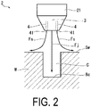
FIG. 2 is a diagram of the laser processing device according to the first embodiment of the present disclosure, as viewed from a scanning direction. -
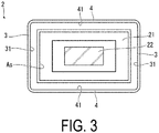
FIG. 3 is a diagram of the laser processing device according to the first embodiment of the present disclosure, as viewed from below. -
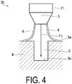
FIG. 4 is a diagram of a laser processing device according to a second embodiment of the present disclosure, as viewed from the scanning direction. -
FIG. 5 is a cross-sectional view illustrating a configuration of a laser processing device according to a third embodiment of the present disclosure. -
FIG. 6 is a diagram of the laser processing device according to the third embodiment of the present disclosure, as viewed from above. -
FIG. 7 is a cross-sectional view illustrating a configuration of a laser processing device according to a fourth embodiment of the present disclosure. - A
laser processing device 100 according to a first embodiment of the present disclosure will be described below with reference toFIG. 1 to FIG. 3 . Thelaser processing device 100 according to the present embodiment is used to perform laser processing on a surface of a workpiece W (a workpiece surface Sw). As illustrated inFIG. 1 , thelaser processing device 100 includes a laser irradiation unit 1 and anozzle assembly 2. - The laser irradiation unit 1 irradiates, from above the workpiece W, the workpiece surface Sw with a laser beam L in a high energy state. As a light source, a YAG laser or a fiber laser can be used, for example. The laser irradiation unit 1 may be the light source, or may be a device that emits the laser beam L reflected by a mirror. Further, a galvanometer mirror can also be used.
- In the present embodiment, as illustrated by an arrow Ds illustrated in
FIG. 1 , thelaser processing device 100 performs scanning in a linear manner or in a curved manner, above the workpiece surface Sw. Cutting (the laser processing) is performed on the workpiece W at a processing point P using a thermal energy of the laser beam L irradiated from the laser irradiation unit 1. As a result of the cutting, a kerf C is formed in the workpiece W. In the example illustrated inFIG. 1 , the kerf C is formed by an end surface Sc on the front side in the scanning direction Ds and a bottom surface Bc extending in a downward direction. By causing the laser beam L to scan, the depth of the bottom surface Bc gradually increases. - The
nozzle assembly 2 is provided for removing a gas, such as the plumes or fumes mentioned above, from the kerf C. Thenozzle assembly 2 includes acover 21, awindow portion 22, acommunication portion 23,jet nozzles 3,side jet nozzles 4, and anintake part 5. - The
cover 21 is disposed above the workpiece surface Sw so as to be spaced apart from the workpiece surface Sw. Thecover 21 is disposed on a path of the laser beam L irradiated from the laser irradiation unit 1. As illustrated inFIG. 1 , thecover 21 bulges in an upward direction to form a convex shape. A suction space Vs, which will be described later, is formed below thecover 21. This suction space Vs is communicated with the outside by thecommunication portion 23, which is provided in a side surface of thecover 21. Further, as illustrated as an example inFIG. 3 , thecover 21 has a rectangular shape when viewed from below. Note that the shape of thecover 21 is not limited to the rectangular shape, and may be a circular or oval shape. Thewindow portion 22 is provided in a central portion of thecover 21. Thewindow portion 22 is formed of a material, such as glass, through which the laser beam L can be transmitted. - As illustrated in
FIG. 1 , thejet nozzles 3 are respectively provided on front and rear sides of thecover 21 in the scanning direction Ds. Thejet nozzles 3 form jet flows Fj by jetting a gas, which has been guided from a supply source (not illustrated), frominjection ports 31 downward (toward the bottom surface Bc). As illustrated inFIG. 3 , theinjection ports 31 extend in the horizontal direction (a width direction) orthogonal to the scanning direction Ds. - As illustrated in
FIG. 2 orFIG. 3 , theside jet nozzles 4 are provided on both sides of thejet nozzles 3 in the width direction. Theside jet nozzles 4 extend in the scanning direction Ds. Theside jet nozzles 4 form side jet flows Fs by jetting air fromside injection ports 41 toward both sides, in the width direction, of the kerf C in the workpiece surface Sw (seeFIG. 2 ). Theside injection ports 41 and theinjection ports 31 are communicated with each other so as to form an annular opening when viewed from below. The processing point P is surrounded by the side jet flows Fs and the above-described jet flows Fj, from both sides in the width direction and the front-rear direction. As a result, the processing point P is sealed from the periphery. - As illustrated in
FIG. 1 , theintake part 5 includes the suction space Vs formed below the above-describedcover 21, and a blower B. The blower B sucks a gas inside the suction space Vs through thecommunication portion 23 described above. As a result, a region below the suction space Vs (that is, a region surrounded by the jet flows Fj and the side jet flows Fs) is in a negative pressure state (referred to as a negative pressure space Vn). - A boundary surface below the suction space Vs (that is, an opening on the lower side of the cover 21) is formed as a suction port As. The suction port As is positioned above the
injection ports 31 of thejet nozzles 3 in the vertical direction. Furthermore, as illustrated inFIG. 3 , an opening area of the suction port As is set to be larger than a sum of opening areas of theinjection ports 31 and theside injection ports 41. Further, the opening area of the suction port As is set to be larger than the opening area of theinjection ports 31. - In a state in which the negative pressure space Vn is formed as described above, the
nozzle assembly 2 moves integrally with the laser irradiation unit 1 following the laser irradiation unit 1 in the scanning direction Ds. In other words, thenozzle assembly 2 is fixed to the laser irradiation unit 1. - Next, an operation of the
laser processing device 100 according to the present embodiment will be described. The laser beam L irradiated from the laser irradiation unit 1 is irradiated onto the workpiece surface Sw. The kerf C is formed in the workpiece W by thelaser processing device 100 reciprocating (scanning) in the scanning direction Ds in a linear manner or in a curved manner. - Here, when performing the above-described laser processing with respect to the workpiece W formed of CFRP, a portion of the workpiece W is burned or melted due to the thermal energy of the laser beam L, and as a result, plumes or fumes are generated. When such plumes or fumes are generated, a cutting surface of the workpiece W is altered as a result of being exposed to a high temperature of the gas, and a heat-affected layer may be formed on the cutting surface. When the laser processing is performed on the CFRP, the heat-affected layer is formed as a result of a resin component of the CFRP dropping off or being carbonized. The heat-affected layer is unnecessary, in order to secure product quality. Therefore, there has been demand for a technology for suppressing the formation of the heat-affected layer.
- Thus, in the
laser processing device 100 according to the present embodiment, the plumes and fumes described above are removed by thenozzle assembly 2. According to the configuration described above, a certain region of the kerf C is isolated from the outside by the jet flows Fj jetted from thejet nozzles 3, and at the same time, the gas is sucked from this region by theintake part 5. Thus, this region obtains a negative pressure state (thus forming the negative pressure space Vn). As a result, a suction force by theintake part 5 can reach a bottom portion of the kerf C. On the other hand, when only the suction is performed without isolating the region using the jet flows Fj, the suction force may not reach the bottom surface Bc of the kerf C, and the plumes or fumes may remain in the kerf C. According to the configuration described above, since the suction is performed by theintake part 5 in a state in which the certain region of the kerf C is isolated by the jet flows Fj, the suction force can reach the bottom portion of the kerf C. As a result, the plumes and fumes can be removed by theintake part 5 in a stable manner. - Furthermore, since the suction port As of the
intake part 5 is provided above theinjection ports 31 of thejet nozzles 3, a phenomenon (a short circuit) in which the jet flows Fj are sucked by theintake part 5 before reaching the bottom portion of the kerf C can be avoided. - Further, according to the configuration described above, the opening area of the suction port As of the
intake part 5 is larger than the opening area of theinjection ports 31. In this way, a flow rate of the gas sucked by theintake part 5 can be made lower than a flow rate of the jet flow Fj. As a result, it is possible to further suppress the phenomenon (the short circuit) in which the jet flows Fj are sucked by theintake part 5 before reaching the bottom portion of the kerf C. - In addition, according to the configuration described above, the
cover 21 covers the suction port As from above, and at the same time, thecover 21 is provided with thewindow portion 22 through which the laser beam L can be transmitted. In this way, the gas can be sucked by theintake part 5 from above the processing point P in a stable manner without blocking an irradiation direction of the laser beam L. As a result, the possibility of the plumes or fumes remaining in the kerf C can be further reduced. - Furthermore, according to the configuration described above, the
side jet nozzles 4 form the side jet flows Fs. As a result, in addition to the processing point P being surrounded, from the front-rear direction, by the jet flows of thejet nozzles 3, the processing point P can be surrounded from the sides by the side jet flows Fs. By sucking the gas in the region surrounded by theintake part 5, the negative pressure state can be maintained in a more stable manner. - Furthermore, according to the configuration described above, as a result of the
nozzle assembly 2, including thejet nozzles 3 and theintake part 5, following the laser irradiation unit 1, it is possible to remove the plumes and fumes in a constant and stable manner in accordance with the position of the processing point P. - Next, a second embodiment of the present disclosure will be described with reference to
FIG. 4 . Note that the same components as those of the first embodiment will be denoted by the same reference signs, and a detailed description thereof will be omitted. As illustrated inFIG. 4 , in anozzle assembly 2b according to the present embodiment,skirt portions 6 are provided in place of theside jet nozzles 4 described above. Theskirt portion 6 extends downward from a side edge of thecover 21. Theskirt portion 6 has a membrane-like shape formed from a material that can elastically deform, such as rubber, for example. Theskirt portion 6 may be divided into a plurality of sections in the front-rear direction. The lower end of theskirt portion 6 is in contact with the workpiece surface Sw. More specifically, the further downward theskirt portion 6 extends, the further theskirt portion 6 extends in a direction away from the kerf C. As a result, a state is obtained in which the inner surface of theskirt portion 6 is in contact with the workpiece surface Sw. - According to the configuration described above, in addition to the processing point P being surrounded, from the front-rear direction, by the jet flows Fj of the
jet nozzles 3, the processing point P can be surrounded from the sides by theskirt portions 6. By sucking the gas in the region surrounded by theintake part 5, the negative pressure state can be maintained in a more stable manner. As a result, the gas generated by the laser processing can be removed in a stable manner. Further, compared with the configuration provided with theside jet nozzles 4 described above, the device can be simplified, and thus it is also possible to reduce manufacturing and maintenance costs. Further, because it is not necessary to form the side jet flows Fs, a gas consumption amount can be reduced by a corresponding amount. - Next, a third embodiment of the present disclosure will be described with reference to
FIG. 5 andFIG. 6 . The same components as those in each of the above-described embodiments will be denoted by the same reference signs, and a detailed description thereof will be omitted. Anozzle assembly 2c according to the present embodiment includes anair injection part 71 and anair intake part 72 in place of thecover 21 described in the first embodiment. As illustrated inFIG. 6 , theair injection part 71 is provided on the inner side of theside jet nozzle 4 on one side in the width direction (that is, on a side on which the kerf C is located). Theair injection part 71 extends in the scanning direction Ds over the same length as theside jet nozzle 4. Theair injection part 71 jets air toward the other side in the width direction. - The
air intake part 72 is provided on the inner side of theside jet nozzle 4 on the other side in the width direction (that is, on the side on which the kerf C is located). Theair intake part 72 extends in the scanning direction Ds over the same length as theside jet nozzle 4. Theair intake part 72 sucks the flow of the air flowing from theair injection part 71. As a result, a membrane-like layer is formed between theair injection part 71 and theair intake part 72 by a flow of air (an air flow Fa) flowing in a direction including a plane intersecting the irradiation direction of the laser beam L. This layer functions as an aerodynamic transmission window through which the laser beam L can be transmitted, while isolating a space below the layer (the negative pressure space Vn) from the outside. Furthermore, as described above, the gas in the negative pressure space Vn is also sucked by an ejector effect generated as a result of the air being sucked by theair intake part 72. In other words, theair injection part 71 and theair intake part 72 also function as anintake part 5c. - According to the configuration described above, the air flow is formed so as to flow from the
air injection part 71 toward theair intake part 72. By this air flow, the region defined by the jet flows Fj from thejet nozzles 3 can be isolated from the outside, from above also. Furthermore, in this region, the ejector effect is generated as a result of the air being sucked by theair intake part 72. In this way, a negative pressure state can be obtained inside the region. As a result, the suction force by theair intake part 72, which serves as theintake part 5c, can reach the bottom portion of the kerf C. Furthermore, since the laser beam L can be transmitted through the air flow formed by theair injection part 71 and theair intake part 72, the air flow functions as the aerodynamic window. As a result, it is possible to prevent the irradiation direction of the laser beam L from being blocked. - Next, a fourth embodiment of the present disclosure will be described with reference to
FIG. 7 . The same components as those in each of the above-described embodiments will be denoted by the same reference signs, and a detailed description thereof will be omitted. As illustrated inFIG. 7 , in anozzle assembly 2d according to the present embodiment, the posture of thejet nozzle 3 is different from that of each of the above-described embodiments. Specifically, on the front side in the scanning direction Ds, thejet nozzle 3 is configured to jet the jet flow Fj toward the front as it flows downward. On the other hand, on the rear side in the scanning direction Ds, thejet nozzle 3 is configured to jet the jet flow Fj toward the rear as it flows downward. - Here, the region surrounded by the jet flows Fj on the front and rear sides is in a negative pressure state as a result of the gas being sucked by the
intake part 5. When the jet flow Fj flows vertically downward, this negative pressure causes the jet flow Fj to be drawn inward and thereby redirected, and the jet flow Fj may not reach the bottom surface Bc of the kerf C. In this case, the isolation of the region becomes insufficient, and thus the negative pressure state cannot be maintained. However, according to the configuration described above, on the front side in the scanning direction Ds, the jet flow Fj is formed so as to flow toward the front as it flows downward. On the rear side in the scanning direction Ds, the jet flow Fj is formed so as to flow toward the rear as the jet flow Fj flows downward. In other words, the further the jet flow Fj flows downward, the further the jet flow Fj flows in a direction away from the processing point P. As a result, the possibility of the jet flow Fj being drawn inward is reduced, and the negative pressure state of the negative pressure space Vn can be maintained in a stable manner. - Each of the embodiments of the present disclosure has been described above. Note that various changes and modifications can be made to the above-described configurations without departing from the gist of the present disclosure. For example, in each of the above-described embodiments, a configuration can be adopted in which the flow rate of the jet flow Fj from the
jet nozzle 3 is varied in the front-rear direction of the scanning direction Ds. - The
laser processing device 100 according to each of the embodiments is understood as follows, for example. - (1) A
laser processing device 100 according to a first aspect includes a laser irradiation unit 1 configured to perform processing on a workpiece W by using a laser beam L, while scanning a workpiece surface Sw, to form a kerf C,jet nozzles 3 respectively provided on front and rear sides in a scanning direction Ds of the laser beam L and configured to form jet flows Fj flowing toward a bottom surface Bc of the kerf C, and anintake part 5 configured to suck, aboveinjection ports 31 of thejet nozzles 3, a gas in a region surrounded by the jet flows Fj from the front and rear sides.
According to the configuration described above, in a state in which a certain region of the kerf C is isolated by the jet flows Fj, theintake part 5 can suck the gas from this region. As a result, a suction force by theintake part 5 can reach the bottom surface Bc of the kerf C. Furthermore, since theintake part 5 is provided above theinjection ports 31, a phenomenon (a short circuit) in which the jet flows Fj are sucked by theintake part 5 before reaching the bottom surface Bc of the kerf C can be avoided. - (2) In the
laser processing device 100 according to a second aspect, an opening area of theintake part 5 is larger than an opening area of theinjection ports 31.
According to the configuration described above, a flow rate of the gas sucked by theintake part 5 can be made lower than a flow rate of the jet flow Fj. As a result, it is possible to further suppress the phenomenon (the short circuit) in which the jet flows Fj are sucked by theintake part 5 before reaching the bottom surface Bc of the kerf C. - (3) The
laser processing device 100 according to a third aspect further includes acover 21 covering the workpiece W from above, and awindow portion 22 provided in thecover 21 and configured to transmit the laser beam L.
According to the configuration described above, thecover 21 is provided with thewindow portion 22 through which the laser beam L can be transmitted. In this way, the gas can be sucked by theintake part 5 from above the processing point P in a stable manner without blocking an irradiation direction of the laser beam L. - (4) In the
laser processing device 100 according to a fourth aspect, theintake part 5c further includes anair injection part 71 provided between thejet nozzles 3 and configured to jet air from one side in a direction including a plane intersecting an irradiation direction of the laser beam L, and anair intake part 72 configured to suck the air jetted from theair injection part 71.
According to the configuration described above, the air flow is formed so as to flow from theair injection part 71 toward theair intake part 72. By this air flow, the region defined by the jet flows Fj from thejet nozzles 3 can be isolated from the outside, from above also. Furthermore, in this region, the ejector effect is generated as a result of the air being sucked by theair intake part 72. In this way, a negative pressure state can be obtained inside the region. Furthermore, since the laser beam L can be transmitted through the air flow formed by theintake part 5c, the air flow functions as an aerodynamic window. As a result, it is possible to prevent the irradiation direction of the laser beam L from being blocked. - (5) The
laser processing device 100 according to a fifth aspect further includesside jet nozzles 4 provided on both sides of thejet nozzle 3 in a width direction orthogonal to the scanning direction Ds, extending in the scanning direction Ds, and configured to form side jet flows Fs flowing toward both sides in a width direction of the kerf C in the workpiece surface Sw.
According to the configuration described above, in addition to the processing point P being surrounded, from the front and rear sides, by the jet flows Fj, the processing point P can also be surrounded from the sides by the side jet flows Fs. By sucking the gas in the region surrounded by theintake part 5, the negative pressure state can be maintained in a more stable manner. - (6) The
laser processing device 100 according to a sixth aspect further includesskirt portions 6 provided on both sides of thejet nozzle 3 in a width direction orthogonal to the scanning direction Ds, and extending in the scanning direction Ds, a lower end of each of theskirt portions 6 being in contact with the workpiece surface Sw.
According to the configuration described above, in addition to the processing point P being surrounded, from the front and rear sides, by the jet flows Fj, the processing point P can also be surrounded from the sides by theskirt portions 6. By sucking the gas in the region surrounded by theintake part 5, the negative pressure state can be maintained in a more stable manner. Further, because it is not necessary to form the side jet flows Fs, a gas consumption amount can be reduced by a corresponding amount. - (7) In the
laser processing device 100 according to a seventh aspect, thejet nozzle 3 is configured to jet, on the front side in the scanning direction Ds, the jet flow Fj toward the front as the jet flow Fj flows downward, and to jet, on the rear side in the scanning direction Ds, the jet flow Fj toward the rear as the jet flow Fj flows downward.
According to the configuration described above, on the front side in the scanning direction Ds, the jet flow Fj is formed so as to flow toward the front as the jet flow Fj flows downward. On the rear side in the scanning direction Ds, the jet flow Fj is formed so as to flow toward the rear as the jet flow Fj flows downward. As a result, the possibility of the jet flow Fj being drawn inward is reduced, and the negative pressure state of the region surrounded, on the front and rear sides, by the jet flows Fj can be maintained in a stable manner. - (8) In the
laser processing device 100 according to an eighth aspect, thejet nozzles 3 and theintake part 5 move integrally with the laser irradiation unit 1 following the laser irradiation unit 1 in the scanning direction Ds. - According to the configuration described above, as a result of the
jet nozzles 3 and theintake part 5 following the laser irradiation unit 1, it is possible to remove the plumes and fumes in a constant and stable manner in accordance with the position of the processing point P. -
- 100 Laser processing device
- 1 Laser irradiation unit
- 2, 2b, 2c, 2d Nozzle assembly
- 3 Jet nozzle
- 4 Side jet nozzle
- 5, 5c Intake part
- 6 Skirt portion
- 21 Cover
- 22 Window portion
- 23 Communication portion
- 31 Injection port
- 41 Side injection port
- 71 Air injection part
- 72 Air intake part
- As Suction port
- B Blower
- Bc Bottom surface
- C Kerf
- Ds Scanning direction
- Fa Air flow
- Fj Jet flow
- Fs Side jet flow
- L Laser
- P Processing point
- Sw Workpiece surface
- W Workpiece
- Vn Negative pressure space
- Vs Suction space
Claims (8)
- A laser processing device comprising:a laser irradiation unit configured to perform processing on a workpiece by using a laser, while scanning a workpiece surface, to form a kerf;jet nozzles respectively provided on front and rear sides in a scanning direction of the laser and configured to form jet flows flowing toward a bottom surface of the kerf; andan intake part configured to suck, above injection ports of the jet nozzles, a gas in a region surrounded by the jet flows from the front and rear sides.
- The laser processing device according to claim 1, wherein
an opening area of the intake part is larger than an opening area of the injection ports. - The laser processing device according to claim 1 or 2, further comprising:a cover covering the workpiece from above; anda window portion provided in the cover and configured to transmit the laser.
- The laser processing device according to claim 1 or 2, whereinthe intake part includes an air injection part provided between the jet nozzles and configured to jet air from one side in a direction including a plane intersecting an irradiation direction of the laser; andan air intake part configured to suck the air jetted from the air injection part.
- The laser processing device according to any one of claims 1 to 4, further comprising:
side jet nozzles provided on both sides of the jet nozzle in a width direction orthogonal to the scanning direction, extending in the scanning direction, and configured to form side jet flows flowing toward both sides in a width direction of the kerf in the workpiece surface. - The laser processing device according to any one of claims 1 to 5, further comprising:
skirt portions provided on both sides of the jet nozzle in a width direction orthogonal to the scanning direction, and extending in the scanning direction, a lower end of each of the skirt portions being in contact with the workpiece surface. - The laser processing device according to any one of claims 1 to 6, wherein
the jet nozzle is configured to jet, on the front side in the scanning direction, the jet flow toward the front as the jet flow flows downward, and to jet, on the rear side in the scanning direction, the jet flow toward the rear as the jet flow flows downward. - The laser processing device according to any one of claims 1 to 7, wherein
the jet nozzles and the intake part move integrally with the laser irradiation unit following the laser irradiation unit in the scanning direction.
Applications Claiming Priority (1)
| Application Number | Priority Date | Filing Date | Title |
|---|---|---|---|
| JP2020038772A JP2021137856A (en) | 2020-03-06 | 2020-03-06 | Laser processing device |
Publications (1)
| Publication Number | Publication Date |
|---|---|
| EP3875210A1 true EP3875210A1 (en) | 2021-09-08 |
Family
ID=74236039
Family Applications (1)
| Application Number | Title | Priority Date | Filing Date |
|---|---|---|---|
| EP21153210.6A Withdrawn EP3875210A1 (en) | 2020-03-06 | 2021-01-25 | Laser processing device with gas ports and central suction port |
Country Status (4)
| Country | Link |
|---|---|
| US (1) | US20210276132A1 (en) |
| EP (1) | EP3875210A1 (en) |
| JP (1) | JP2021137856A (en) |
| CN (1) | CN113427125A (en) |
Families Citing this family (2)
| Publication number | Priority date | Publication date | Assignee | Title |
|---|---|---|---|---|
| JP2023146173A (en) * | 2022-03-29 | 2023-10-12 | 本田技研工業株式会社 | Workpiece processing device |
| CN115958290A (en) * | 2023-01-20 | 2023-04-14 | 通快(中国)有限公司 | Gas-assisted device for laser welding and laser welding system |
Citations (5)
| Publication number | Priority date | Publication date | Assignee | Title |
|---|---|---|---|---|
| JPH03258483A (en) | 1990-03-06 | 1991-11-18 | Mitsubishi Heavy Ind Ltd | Dust collector of laser beam machine |
| US20040112882A1 (en) * | 2002-09-05 | 2004-06-17 | Hidekazu Miyairi | Laser processing apparatus |
| JP2011092967A (en) * | 2009-10-28 | 2011-05-12 | Mitsubishi Electric Corp | Laser scribing apparatus |
| US20170136576A1 (en) * | 2014-03-27 | 2017-05-18 | Fukui Prefectural Government | Suction method, suction device, laser processing method, and laser processing device |
| DE102016116659A1 (en) * | 2016-09-06 | 2018-03-08 | Laser On Demand Gmbh | Laser welding device and laser welding process for laser welding of metallic workpieces |
Family Cites Families (9)
| Publication number | Priority date | Publication date | Assignee | Title |
|---|---|---|---|---|
| FR2826893B1 (en) * | 2001-07-05 | 2003-09-19 | Snecma Moteurs | MINIATURIZED LASER BEAM WELDING APPARATUS |
| FR2891483B1 (en) * | 2005-10-05 | 2009-05-15 | Commissariat Energie Atomique | METHOD AND INSTALLATION OF LASER CUTTING / WELDING |
| US7456370B2 (en) * | 2006-01-30 | 2008-11-25 | Honeywell International Inc. | Welding shield and flexible skirt for automated welding |
| JP5104914B2 (en) * | 2010-06-30 | 2012-12-19 | 三星ダイヤモンド工業株式会社 | Removal equipment |
| CA2814185A1 (en) * | 2010-09-10 | 2012-07-12 | Christopher DACKSON | Method and apparatus for laser welding with mixed gas plasma suppression |
| KR101962661B1 (en) * | 2011-09-15 | 2019-03-27 | 니폰 덴키 가라스 가부시키가이샤 | Glass plate cutting method and glass plate cutting device |
| CN103831531B (en) * | 2012-11-23 | 2016-09-14 | 通用汽车环球科技运作有限责任公司 | Welding point |
| JP6450784B2 (en) * | 2017-01-19 | 2019-01-09 | ファナック株式会社 | Laser processing machine |
| JP6945011B2 (en) * | 2017-12-18 | 2021-10-06 | 本田技研工業株式会社 | 3D modeling equipment |
-
2020
- 2020-03-06 JP JP2020038772A patent/JP2021137856A/en not_active Withdrawn
-
2021
- 2021-01-25 EP EP21153210.6A patent/EP3875210A1/en not_active Withdrawn
- 2021-01-26 US US17/158,264 patent/US20210276132A1/en not_active Abandoned
- 2021-01-26 CN CN202110104268.XA patent/CN113427125A/en active Pending
Patent Citations (5)
| Publication number | Priority date | Publication date | Assignee | Title |
|---|---|---|---|---|
| JPH03258483A (en) | 1990-03-06 | 1991-11-18 | Mitsubishi Heavy Ind Ltd | Dust collector of laser beam machine |
| US20040112882A1 (en) * | 2002-09-05 | 2004-06-17 | Hidekazu Miyairi | Laser processing apparatus |
| JP2011092967A (en) * | 2009-10-28 | 2011-05-12 | Mitsubishi Electric Corp | Laser scribing apparatus |
| US20170136576A1 (en) * | 2014-03-27 | 2017-05-18 | Fukui Prefectural Government | Suction method, suction device, laser processing method, and laser processing device |
| DE102016116659A1 (en) * | 2016-09-06 | 2018-03-08 | Laser On Demand Gmbh | Laser welding device and laser welding process for laser welding of metallic workpieces |
Also Published As
| Publication number | Publication date |
|---|---|
| JP2021137856A (en) | 2021-09-16 |
| CN113427125A (en) | 2021-09-24 |
| US20210276132A1 (en) | 2021-09-09 |
Similar Documents
| Publication | Publication Date | Title |
|---|---|---|
| JP5964693B2 (en) | Substance collection method and substance collection apparatus | |
| KR101552562B1 (en) | Particle suction apparatus and laser processing system having the same | |
| KR102921742B1 (en) | Laser processing apparatus | |
| JP6647829B2 (en) | Laser processing equipment | |
| JP6255595B2 (en) | Cleaving device | |
| EP3875210A1 (en) | Laser processing device with gas ports and central suction port | |
| CN1572015A (en) | Film removing apparatus, film removing method and substrate processing system | |
| JP2017100170A (en) | Debris recovery mechanism and laser processing device | |
| KR20190049985A (en) | Laser apparatus | |
| JP6124425B1 (en) | Laser processing device rectifier and laser processing device | |
| KR20190088141A (en) | Laser apparatus | |
| CN108857056B (en) | Laser processing device | |
| JP7668521B2 (en) | Optical equipment protection device and laser processing device | |
| JP2014104489A (en) | Laser processing device and dust collection method for laser processing device | |
| JP5355349B2 (en) | Laser scribing device | |
| JP2010120038A (en) | Laser beam machining apparatus and method | |
| JP6605976B2 (en) | Cutting equipment | |
| KR20230085864A (en) | Laser processing apparatus and debris removing apparatus | |
| WO2021058545A1 (en) | Assembly of a laser ablation apparatus and laser ablation apparatus of such an assembly | |
| KR102193655B1 (en) | Machining room | |
| KR102198909B1 (en) | Apparatus for collecting non-product | |
| JP6269876B2 (en) | Cleaving device | |
| JP2013240835A (en) | Laser beam machining device and laser beam machining method |
Legal Events
| Date | Code | Title | Description |
|---|---|---|---|
| PUAI | Public reference made under article 153(3) epc to a published international application that has entered the european phase |
Free format text: ORIGINAL CODE: 0009012 |
|
| STAA | Information on the status of an ep patent application or granted ep patent |
Free format text: STATUS: THE APPLICATION HAS BEEN PUBLISHED |
|
| AK | Designated contracting states |
Kind code of ref document: A1 Designated state(s): AL AT BE BG CH CY CZ DE DK EE ES FI FR GB GR HR HU IE IS IT LI LT LU LV MC MK MT NL NO PL PT RO RS SE SI SK SM TR |
|
| STAA | Information on the status of an ep patent application or granted ep patent |
Free format text: STATUS: REQUEST FOR EXAMINATION WAS MADE |
|
| 17P | Request for examination filed |
Effective date: 20220103 |
|
| RBV | Designated contracting states (corrected) |
Designated state(s): AL AT BE BG CH CY CZ DE DK EE ES FI FR GB GR HR HU IE IS IT LI LT LU LV MC MK MT NL NO PL PT RO RS SE SI SK SM TR |
|
| STAA | Information on the status of an ep patent application or granted ep patent |
Free format text: STATUS: EXAMINATION IS IN PROGRESS |
|
| 17Q | First examination report despatched |
Effective date: 20220523 |
|
| GRAP | Despatch of communication of intention to grant a patent |
Free format text: ORIGINAL CODE: EPIDOSNIGR1 |
|
| STAA | Information on the status of an ep patent application or granted ep patent |
Free format text: STATUS: GRANT OF PATENT IS INTENDED |
|
| INTG | Intention to grant announced |
Effective date: 20230303 |
|
| STAA | Information on the status of an ep patent application or granted ep patent |
Free format text: STATUS: THE APPLICATION IS DEEMED TO BE WITHDRAWN |
|
| 18D | Application deemed to be withdrawn |
Effective date: 20230714 |