EP3875175A1 - Glue distributor assembly for edgebanding machine and method of panel edgebanding - Google Patents
Glue distributor assembly for edgebanding machine and method of panel edgebanding Download PDFInfo
- Publication number
- EP3875175A1 EP3875175A1 EP21157033.8A EP21157033A EP3875175A1 EP 3875175 A1 EP3875175 A1 EP 3875175A1 EP 21157033 A EP21157033 A EP 21157033A EP 3875175 A1 EP3875175 A1 EP 3875175A1
- Authority
- EP
- European Patent Office
- Prior art keywords
- contacting roll
- glue
- roll
- distributor assembly
- contacting
- Prior art date
- Legal status (The legal status is an assumption and is not a legal conclusion. Google has not performed a legal analysis and makes no representation as to the accuracy of the status listed.)
- Granted
Links
Images



Classifications
-
- B—PERFORMING OPERATIONS; TRANSPORTING
- B05—SPRAYING OR ATOMISING IN GENERAL; APPLYING FLUENT MATERIALS TO SURFACES, IN GENERAL
- B05C—APPARATUS FOR APPLYING FLUENT MATERIALS TO SURFACES, IN GENERAL
- B05C1/00—Apparatus in which liquid or other fluent material is applied to the surface of the work by contact with a member carrying the liquid or other fluent material, e.g. a porous member loaded with a liquid to be applied as a coating
- B05C1/006—Apparatus in which liquid or other fluent material is applied to the surface of the work by contact with a member carrying the liquid or other fluent material, e.g. a porous member loaded with a liquid to be applied as a coating for applying liquid or other fluent material to the edges of essentially flat articles
-
- B—PERFORMING OPERATIONS; TRANSPORTING
- B05—SPRAYING OR ATOMISING IN GENERAL; APPLYING FLUENT MATERIALS TO SURFACES, IN GENERAL
- B05C—APPARATUS FOR APPLYING FLUENT MATERIALS TO SURFACES, IN GENERAL
- B05C1/00—Apparatus in which liquid or other fluent material is applied to the surface of the work by contact with a member carrying the liquid or other fluent material, e.g. a porous member loaded with a liquid to be applied as a coating
- B05C1/04—Apparatus in which liquid or other fluent material is applied to the surface of the work by contact with a member carrying the liquid or other fluent material, e.g. a porous member loaded with a liquid to be applied as a coating for applying liquid or other fluent material to work of indefinite length
- B05C1/08—Apparatus in which liquid or other fluent material is applied to the surface of the work by contact with a member carrying the liquid or other fluent material, e.g. a porous member loaded with a liquid to be applied as a coating for applying liquid or other fluent material to work of indefinite length using a roller or other rotating member which contacts the work along a generating line
- B05C1/0813—Apparatus in which liquid or other fluent material is applied to the surface of the work by contact with a member carrying the liquid or other fluent material, e.g. a porous member loaded with a liquid to be applied as a coating for applying liquid or other fluent material to work of indefinite length using a roller or other rotating member which contacts the work along a generating line characterised by means for supplying liquid or other fluent material to the roller
-
- B—PERFORMING OPERATIONS; TRANSPORTING
- B27—WORKING OR PRESERVING WOOD OR SIMILAR MATERIAL; NAILING OR STAPLING MACHINES IN GENERAL
- B27D—WORKING VENEER OR PLYWOOD
- B27D5/00—Other working of veneer or plywood specially adapted to veneer or plywood
- B27D5/003—Other working of veneer or plywood specially adapted to veneer or plywood securing a veneer strip to a panel edge
-
- B—PERFORMING OPERATIONS; TRANSPORTING
- B27—WORKING OR PRESERVING WOOD OR SIMILAR MATERIAL; NAILING OR STAPLING MACHINES IN GENERAL
- B27G—ACCESSORY MACHINES OR APPARATUS FOR WORKING WOOD OR SIMILAR MATERIALS; TOOLS FOR WORKING WOOD OR SIMILAR MATERIALS; SAFETY DEVICES FOR WOOD WORKING MACHINES OR TOOLS
- B27G11/00—Applying adhesives or glue to surfaces of wood to be joined
-
- B—PERFORMING OPERATIONS; TRANSPORTING
- B05—SPRAYING OR ATOMISING IN GENERAL; APPLYING FLUENT MATERIALS TO SURFACES, IN GENERAL
- B05C—APPARATUS FOR APPLYING FLUENT MATERIALS TO SURFACES, IN GENERAL
- B05C1/00—Apparatus in which liquid or other fluent material is applied to the surface of the work by contact with a member carrying the liquid or other fluent material, e.g. a porous member loaded with a liquid to be applied as a coating
- B05C1/04—Apparatus in which liquid or other fluent material is applied to the surface of the work by contact with a member carrying the liquid or other fluent material, e.g. a porous member loaded with a liquid to be applied as a coating for applying liquid or other fluent material to work of indefinite length
- B05C1/08—Apparatus in which liquid or other fluent material is applied to the surface of the work by contact with a member carrying the liquid or other fluent material, e.g. a porous member loaded with a liquid to be applied as a coating for applying liquid or other fluent material to work of indefinite length using a roller or other rotating member which contacts the work along a generating line
- B05C1/0817—Apparatus in which liquid or other fluent material is applied to the surface of the work by contact with a member carrying the liquid or other fluent material, e.g. a porous member loaded with a liquid to be applied as a coating for applying liquid or other fluent material to work of indefinite length using a roller or other rotating member which contacts the work along a generating line characterised by means for removing partially liquid or other fluent material from the roller, e.g. scrapers
-
- B—PERFORMING OPERATIONS; TRANSPORTING
- B05—SPRAYING OR ATOMISING IN GENERAL; APPLYING FLUENT MATERIALS TO SURFACES, IN GENERAL
- B05C—APPARATUS FOR APPLYING FLUENT MATERIALS TO SURFACES, IN GENERAL
- B05C1/00—Apparatus in which liquid or other fluent material is applied to the surface of the work by contact with a member carrying the liquid or other fluent material, e.g. a porous member loaded with a liquid to be applied as a coating
- B05C1/04—Apparatus in which liquid or other fluent material is applied to the surface of the work by contact with a member carrying the liquid or other fluent material, e.g. a porous member loaded with a liquid to be applied as a coating for applying liquid or other fluent material to work of indefinite length
- B05C1/08—Apparatus in which liquid or other fluent material is applied to the surface of the work by contact with a member carrying the liquid or other fluent material, e.g. a porous member loaded with a liquid to be applied as a coating for applying liquid or other fluent material to work of indefinite length using a roller or other rotating member which contacts the work along a generating line
- B05C1/086—Apparatus in which liquid or other fluent material is applied to the surface of the work by contact with a member carrying the liquid or other fluent material, e.g. a porous member loaded with a liquid to be applied as a coating for applying liquid or other fluent material to work of indefinite length using a roller or other rotating member which contacts the work along a generating line a pool of coating material being formed between a roller, e.g. a dosing roller and an element cooperating therewith
- B05C1/0865—Apparatus in which liquid or other fluent material is applied to the surface of the work by contact with a member carrying the liquid or other fluent material, e.g. a porous member loaded with a liquid to be applied as a coating for applying liquid or other fluent material to work of indefinite length using a roller or other rotating member which contacts the work along a generating line a pool of coating material being formed between a roller, e.g. a dosing roller and an element cooperating therewith the cooperating element being a roller, e.g. a coating roller
Definitions
- the present invention refers to a glue distributor assembly, associable to the edgebanding machine, and a method to carry out panel edgebanding.
- Wood panels, solid wood or derivatives thereof, for example chipboard or also plastic material, are used to manufature furnitures, shelving units, shelves and they are generally manufactured with two opposed flat faces and with an edge which is perpendicular to faces.
- the two faces of the raw panels are covered with a foil of ennobled material in suitable processing centers, in order to obtain the desired surface finishing and appearance, wherein such foils can have various colors, appearance, finishing and finishings.
- the edgebanding machines has the function of applying a tape finishing element on the panel edge under processing, such that to ennobling also the panel edge.
- the tape finishing element can also be defined as profile, listel or strip, and it is commonly made of synthetic material.
- the tape finishing element will be named profile, or finishing profile, or edge profile.
- the finishing profiles are glued on the corresponding panel edge, remaining raw after the ennobling of the two faces of the panel.
- the finishing profile is usually applied as protruding: the profile has a width higher than the one of the panel board to which it is glued, in order to be sure to obtain a perfect covering of the edge and, in general, of the panel.
- the splicing is an operation through which the finishing profile is cut to the same length of the panel board; the subsequent trimming operation involves the removal of the higher and lower portions of the finishing profile transversally protruding from the panel edge, beyond the faces.
- the splicing and the trimming are respectively carried out by specific splicing and trimming assembly, respectively; the first moving for a certain period of time together with the panel under processing, i.e. they move jointly to the panels for the time necessary to cut the part of the finishing profile exceeding in length, the second being stationary and carrying out the trimming taking advantage of the panel movement advancing in the edgebanding machine.
- the panel thus processed is then finished with the removal of processing waste and residues, by scrapers and brushes.
- edgebanding machine will be equipped with molded tools in a substantially complementary way with respect to the panel edge.
- edgebanding machine or components thereof: EP 1997597 , EP 2251165 , EP 2062706 , EP 2052822 , EP 1785243 , EP 1588812 , EP 1464470 , EP 0945235 , EP1260277 .
- An object of the present invention is a glue distributor assembly, or more simply a distributor assembly, intended to be installed on a edgebanding machine in order to allow a precise and effective glue application on the panel edge to be ennobled with the finishing profile, and / or in order to allow the precise and effective glue application on the same profile.
- a typical distributor assembly comprises a contacting roll, generally metallic and knurled, configurable to roll on the panel edge, or on the finishing profile, and releasing a glue amount on the related surface, which is sufficient to guarantee the right fastening of the profile on the panel edge.
- the contacting roll is motorized and the related rotation axis is maintained parallel to the surface of the panel edge under processing, or the surface of the finishing profile to be glued.
- the distributor assembly further comprises a heated tank, since the glue commonly used is of the thermal fuse polyurethane-type (PU, PUR, HMPUR), i.e. a glue with a relatively high melting temperature, usually included between 100°C and 140°C, which is to be hot-applied, being liquid, and cross-linking by reaction of isocyanate groups with the air humidity resulting in three-dimensional polyethers and / or polyurethane polyesters, comprising ureic bonds.
- glues containing ethylene vinyl acetate (EVA)-based thermoplastic resins are used, the latter also being hot-applied.
- At least one squeegee is arranged adjacent to the contacting roll, or a blade or a distributing blade-function element which together with the contacting roll defines the useful section for the glue passage towards the panel edge under processing.
- the glue is suitably distributed from the related container to the contacting roll surface, and then being distributed on the panel edge or on the finishing profile, before these two elements are pressed against one another in the edgebanding machine.
- the thickness of the glue layer deposited on the panel edge depends, as anticipated above, on the interstice defined between the squeegee, or the squeegees when more than one, and the contacting roll. Such thickness is adjustable, involving the possibility to adjust, i.e. precisely adjusting the position of the squeegee or squeegees with respect to the contacting roll.
- a first limit relates to the maintenance of glue distributor assemblies.
- the cleaning of the contacting roll is complex, since it is not easy when the distributor assembly is assembled on the edgebanding machine, and a complete disassembly of the distributor assembly, i.e. its removal from the edgebanding machine and disassembly, is often necessary to obtain a deep cleaning.
- the disassembly of the distributor assembly requires a machine downtown, during which the edgebanding machine cannot operate.
- a second limit consists in that, the glue firstly contained in the related tank, and then fed to the contacting roll, can be homogeneous: due to the fact that the temperature distribution between the inner surface of the tank, the outer surface of the contacting roll and the squeegee outer surface can be uniform, over the time the glue can have a different viscosity between one point and another of the distributor assembly and, in the worst case, clumps can be formed or it can locally crosslink.
- a third limit consists in that, the squeegees can damage the contacting roll surface when, during the maintenance operation, are brought to limit stop, in the position of minimum distance from the contacting roll. This case can be critical, since the squeegees can contact the surface of the contacting roll and damaging it if applied with high pressure.
- there is a persistent need to nullify the glue passage section i.e. there is the need for the user, during some operations of maintenance or testing, or fine-tuning of the edgebanding machine, to use the squeegees as barrier to completely intercept the glue passage and preventing the glue to reach the panel.
- a forth limit relates to the thickness variability of panels to be edgebanded and, accordingly, the finishing profiles height: based on the production batch, the panels can have an higher or lower thickness, or can change the height of the panel edge, for example 1.5 cm for a batch and 2 cm for another batch.
- the known distributor assemblies showed to be not very versatile, i.e. not very adaptable, resulting in that, glue distribution is often not optimal, with a dispersion beyond the panel edge, on the related faces, or with an insufficient distribution on the panel edge.
- the results are the excessive fouling of panel faces, and in the second case the consequence is that the adhesion of the finishing profile to the corresponding panel edge is not perfect.
- a fifth limit consists is the tendency of the knurled contacting roll tends to hold wood particles detaching from the edge during panel edgebanding.
- the reason of such phenomenon is mostly due to the double knurling of the contacting roll, right and left, and it defines small rhomboid recesses in which over time, i.e. with the increasing number of edgebanded panels, the accumulated detached particles, are incorporated into the glue and thus affecting the contacting roll.
- a first object of the present invention is to provide a glue distributor assembly which simply and effectively the limits of the solutions today available.
- a first aspect of the present invention relates to a glue distributor assembly according to claim 1, for edgebanding machine.
- the distributor assembly comprises a body provided with a melted glue collecting chamber, and a contacting roll, pivotally supported on the body.
- the collecting chamber of the melted glue can be defined within the body, or it can be external to the body and constrainable to it, such as an outer tank.
- the outer surface of the contacting roll is intended for rolling on a panel edge to be edgebanded, or on a panel finishing profile, to distribute the melted glue collected from the collecting chamber and allowing panels ennoblement.
- the contacting roll is hollow and delimits an inner volume which is connected to the collecting chamber and in use it is crossed by the melted glue.
- the contacting roll has not only the function of distributing the melted glue on the panel edge to be edgebanded, or on the finishing profiles, also being part of a slow circuit of the melted glue, and this feature allows to uniformed temperature distribution in the distributor assembly.
- the melted glue in a specific distributor assembly circuit allows to solve the second drawback described with specific reference to the known solutions, that allows to avoid non-uniformity in the melted glue mass, in particular temperature non-uniformity.
- This result allows to limit or completely preventing clumps formation in the glue, or the crosslinking in glue. Therefore, the proposed solution provides an improvement in the distributor assembly operation, which provides an improved gluing quality, reduced cleaning of the distributor assembly and, accordingly, reduced downtimes of the edgebanding machine.
- the glue collecting chamber is external to the body, it is connected to the flowing circuit through at least a specific connection; alternatively, and preferably, the collecting chamber is directly defined within the distributor assembly body.
- the role of the inner volume of the contacting roll is not limited to the passage of the glue: in the preferred embodiment, the melted glue is subjected to a mixing within the contacting roll, continuous or according to time intervals.
- the inner volume of the contacting roll is configurable as a mixing chamber of the melted glue, arranged in fluid communication with the collecting chamber within the body.
- the mixing of the melted glue within the contacting roll can be obtained through several modes.
- a first mode involves making, above the inner surface, one or more projections, or ribs, so that after the rotation of the contacting roll on their rotation axis the projections, or ribs, provide a thrust on the melted glue, along the contacting roll.
- a second mode which can be implemented alternatively or in addition to the first just described, consists of providing the distributor assembly of a mixing element inserted within the contacting roll.
- the mixing element is pivotable with respect to the contacting roll, and the relative rotation between the mixing element and the melted glue present in the contacting roll generates a thrust on the melted glue along the contacting roll.
- the rotation direction of the contacting roll and the mixing element possibly positioned within defines the direction of the thrust on the melted glue, vertical ascending or vertical descending.
- the projections or ribs, and the mixing element substantially extending as screw, or helix, or double helix.
- the mixing element is inserted in the contacting roll, it is coaxial to the roll and the projections or ribs.
- the collecting chamber extends in the body parallel to the contacting roll, and arranged in fluid communication with the inner volume of the contacting roll, at the ends of the contacting roll.
- the distributor assembly comprises a top pivot and a lower pivot, and the contacting roll is supported on the body by these pivots, which are at least partially inserted in a corresponding end of the contacting roll. At least one between the top pivot and the lower pivot, and preferably both, is/are removable and the removal of the pivot, or pivots, releases the contacting roll from the body, for the disassembly.
- the coupling described above is advantageous since it allows the contacting roll to be assembled on the distributor assembly body, and disassembling the contacting roll from the body, in a simple and rapid manner, without necessarily dismounting the body or removing it from the edgebanding machine, missing the tolerances previously registered. In fact, in order to obtain the cleaning of the contacting roll, or for the substitution thereof, it will be sufficient removing a pivot, or both the pivots, in order to be able to remove the contacting roll from the body, without acting on the body itself.
- the pivots are preferably provided with at least a radial opening allowing the passage of the glue from the inner volume of the contacting roll, i.e. from the mixing chamber, to the collecting chamber, and vice versa.
- the distributor assembly has a through hole extending between an inlet, accessible to the outside of the distributor assembly, and an inner outlet al distributor assembly, by injection of a dye within the distributor assembly.
- the inner outlet of said through hole is arranged in correspondence of the contacting roll or the collecting chamber.
- the injection of the dye is carried out arranging a specific valve on the body of the distributor assembly providing an access to the melted-glue collecting inner chamber, or furthermore, arranging suitable injection means in the collecting chamber when the latter being external to the body.
- the mixing element advantageously allows to obtain a rapid color change of the melted glue color and, especially, a uniform change of all the mass of melted glue present in the flow circuit, rapidly.
- the mixing element can be activated to vigorously mix the melted glue and obtaining a uniform dye distribution.
- the present invention also relates a method, according to claim 16, for the panel edgebanding.
- the method comprises:
- the method also provides arranging the hollow contacting roll and allowing the melted glue to flow from the collecting chamber through the contacting roll, and vice versa, in order to obtain the above described advantages with respect to the distributor assembly.
- the squeegee is substantially cylindrical and is housed in the body of the distributor assembly, parallel to the contacting roll and it is functionally interposed, with glue barrier function, between the outer surface of the contacting roll and the glue collecting chamber.
- the squeegees are two.
- Each squeegee has a flat surface, or flatting, or slot, for example obtained by milling an outer surface portion, defining a side corner of the squeegee.
- Each squeegee is pivotable on its own longitudinal axis, which is parallel to the rotation axis of the contacting roll, and the side corner is accordingly movable between:
- the interstice created between the side corner and the outer surface of the contacting roll, and therefore the thickness of the melted glue on the contacting roll is from 2-3 tenths of a millimeter.
- le squeegees are pivotable on the respective longitudinal axes selectively and independent from each other.
- the activation can be manual, motorized or servo-assisted, and the squeegees can be blocked in the desired angular position.
- the proposed solution allows to effectively adjust, and without malfunctioning risks, the thickness of the glue layer on the contacting roll.
- each squeegee is pivotally on the longitudinal axes thereof, parallel to the rotation axis of the contacting roll.
- the longitudinal axis of each squeegee is at a distance from the rotation axis of the contacting roll corresponding to the sum of the outer radii of the contacting roll and of the squeegee, with a tolerance H/h7. This precaution allows to avoid that a mechanical interference occurs between the squeegees and the contacting roll, and jamming that could cause ruptures.
- the second point 36, for the panel edgebanding relates also to a method, the second point 36, for the panel edgebanding. II method comprises:
- the method also provides:
- a third aspect of the present invention concerns the following optional element optional for the height regulation of the melted glue layer adherent to the outer surface of the contacting roll, where the terms height refers to the extension of the glue layer parallel to the rotation axis of the contacting roll, i.e. parallel to the outer surface of the contacting roll.
- Such adjusting element is even a squeegee, i.e. a cylindrical element, housed in the body parallel to the contacting roll and functionally interposed, with a glue barrier function, between the outer surface of the contacting roll and the glue collecting chamber.
- the squeegees are two.
- Each squeegee has a flat surface, or flatting, e.g. obtained by milling a portion of the outer surface of the squeegee, defining a higher corner of the squeegee.
- Each squeegee is sliding with respect to the contacting roll, on its own longitudinal axis, and the higher corner is accordingly movable between:
- the proposed solution allows to effectively adjust, and without risks of malfunctioning, the height of the glue layer on the contacting roll.
- the squeegees are movable along the respective longitudinal axes, for example moving, selectively and independently from each other.
- the activation can be manual, motorized or servo-assisted, and the squeegees can be blocked in the desired vertical position.
- the present invention is preferably implemented with two squeegee pivotable and sliding on the respective longitudinal axes and provided with both side corner, for adjusting the thickness of the melted glue layer released on the contacting roll, and the higher of the higher corner, for adjusting the height of the melted glue layer released on the contacting roll.
- the distributor assembly comprises, for each squeegee, a seal element, or flap, arranged in the body, in correspondence of the lower end of the respective squeegee, defining a lower corner of the flat surface described above and prevents the leakage of the melted glue from the bottom, i.e. it prevents the that melted glue can pour along the squeegee and leaking from the from the body of the distributor assembly.
- the squeegee being sliding with respect to the seal element thereof to adjust the distance between the higher corner and the lower corner and adjusting, accordingly, the height of the melted glue layer on the contacting roll.
- seal element is constrained to the body and it is blocked against the longitudinal movements against the longitudinal movements.
- the third aspect of the present invention also relates to a method, according to point 37, for the panel edgebanding, comprising:
- the method also provides:
- a for the aspect of the present invention for which the Applicant reserves the possibility to file a divisional patent application, relates to the coupling removable, and interchangeable, of the contacting roll on the body of the distributor assembly, obtained through a fastening element of the ends of the contacting roll of which at least one is removable.
- fastening element are preferably pivots, one higher and one lower to, respectively, constrain the higher end and the lower end of the contacting roll to the body of the distributor assembly.
- Having removable fastening element allows to remove the contacting roll from the body of the distributor assembly, and assembly it again, in a short time, in a simple way and without necessarily disassembling or shifting the body of the distributor assembly.
- the fastening element substantially the pivots, are at least partially hollow and they are part of the flow circuit of the melted glue, meaning that they define a part of the circuit formed by the inner volume of the contacting roll and the collecting chamber of the body.
- the pivots have one or more radial openings exactly to allow the passage of the melted glue from the contacting roll to the collecting chamber, and vice versa.
- the fourth aspect of the present invention also relates to a method, according to point 39, for the panel edgebanding, comprising:
- the method also comprises:
- a fifth element of the present invention for which the Applicant reserves the possibility to file a divisional patent application, related to the following optional feature: in the preferred embodiment the contacting roll does not have an outer surface with knurling or double knurling, but its outer surface has a continuous helicoidal profile. This precaution allows to promote the migration to the ends of the contacting roll di possible solid particles - initially detached from the panels subjected to edgebanding - present on the outer surface of the same contacting roll or incorporated in the glue. In this way, the formation of glue clumps and solid particles or mixtures is limited or completely prevented.
- the above described features is also object of point 40, and correspond to make self-cleaning the contacting roll with respect to the undesired solid particles.
- the attached figures show the preferred embodiment of the glue distributor assembly 100 according to the present invention, hereinafter briefly indicated as distributor assembly.
- the distributor assembly 100 comprises a body 1 supporting the other components.
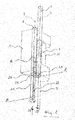
- the body 1 preferably metallic, has a general C-shape C, i.e. it has two horizontal portions ha due horizontal portions 1' joined by a vertical portion 1". Between the horizontal portions 1' a contacting roll 7 is supported, whose rotation axis 9 is vertical, i.e. parallel to the vertical portion 1" of the body 1.
- the contacting roll 7 is intended to constrain by rolling the edge of a panel to be edgeboarded with the finishing profile (not showed), in order to apply on such edge a glue layer sufficient to guarantee the adhesion of a finishing profile, as described below.
- the contacting roll 7 is pivotally assembled on the body 1 and it is motorized.
- the rotation speed, or rpm, are selected such that between the rotating contacting roll 7 and the panels to be edgeboarded, moving on the edgebanding machine, slipping do not occur.
- a first advantageous feature of the distributor assembly 100 for which the Applicant reserves the possibility to file a divisional patent application, consist in the fact that the contacting roll 7 is easily removable from the body 1 of the distributor assembly 100, in a substantially interchangeable way.
- the fastening means are a top pivot 18 and a lower pivot 19, which operate also as bushings for the pivotable support of the contacting roll 7.
- the pivots 18 and 19 are vertically inserted through the horizontal portions 1' of the body 1, coaxially with respect to the rotation axis 9 of the contacting roll 7.
- At least one between the top pivot 18 and the lower pivot 19, and preferably both, are removable from the body 1 of the distributor assembly 100 to allow the disassembly of the contacting roll 7.
- the contacting roll 7 is laterally or frontally from the body 1, simply with one hand.
- top pivot 18 and the lower pivot 19 are inserted without any clearance, or with minimum tolerances, in corresponding sites 18' and 19' obtained in the body 1 of the distributor assembly 100 and blocked by Seager rings, pins or other mechanical fasteners.
- the top pivot 18 and the lower pivot 19 are addressed to the respective sites 18' and 19'.
- the relative rotation between the contacting roll and the pivots 18, 19 is provided.
- some bushings are inserted, for example, made of teflon.
- the contacting roll 7 and the pivots 18 and 19 rotate integral with respect to the body 1, for example supported by bushings or bearings.
- the inner diameter of the contacting roll 7 has a first value at the central portion, and a second value which is higher than the first one at the end, such that the pivots 18 and 19 are inserted in the contacting roll 7 wired with the inner surface of the central portion, such that to define within the contacting roll 7 a perfectly cylindrical volume.
- the coupling between the contacting roll 7 and the body 1 of the distributor assembly 100 allows to solve the first described drawback relating to the prior art.
- the disassembly of the contacting roll 7 is easily obtainable by simply removing the top pivot 18 and the lower pivot 19 from the body 1, and removing the contacting roll 7, the cleaning and the maintenance of the contacting roll 7 are possible rapidly, in a simple way, as the reassembly.
- a mechanical maintenance technician will insert the contacting roll 7 in the body 1, vertically along the rotation axis 9, between the horizontal portions 1' and parallel to the vertical portion 1", and proceeding by inserting the pivots 18 and 19 through the respective sites 18' and 19', so as to complete the coupling by blocking the pivots 18 and 19 on the body 1.
- the distributor assembly 100 comprises a guard element 2 screwed to the body 1 with screws 2', frontally at the lower horizontal portion 1'.
- the guard element 2 protrudes beyond the higher edge of the lower horizontal portion 1' such that to delimit collecting tray 2" of the residual or excess glue, possibly casted from the contacting roll 7.
- the guard element 2 guarantee that the contacting roll 7 cannot be disassembly from the body 1 without having previously unscrewed and separated the guard element 2 itself.
- a first method of edgebanding according to the present invention provides, therefore, the easy disassembly of the contacting roll 7 from the body 1, simply removing the pivots 18 and 19 and removing the roll from the body 1.
- the contacting roll 7 is removable from the horizontal portions 1' of the body 1 of the distributor assembly 100, simply pulling with a hand.
- the method also involves an easy reassembly of the contacting roll 7: it will be sufficient to reposition the contacting roll 7 between the horizontal portions 1' of the body 1, coaxially to the rotation axis 9, and subsequently inserting pivots 18 and 19 in the respective sites 18' and 19' through le horizontal portions 1' of the body 1.
- a second advantageous feature of the distributor assembly 100 is constituted by the fact that the contacting roll 7 is internally hollow, and the melted glue, i.e. maintained to a temperature higher to the related melting temperature, is allowed to flow and the melting glue is continuously mixed at the molten state, i.e. maintained at a temperature higher to the related melting temperature.
- the top pivot 18 and the lower pivot 19 are hollow, such that to allow the passage of the melted glue, and the inner volume of the contacting roll 7 delimits a mixing chamber 7' of the melted glue.
- the mixing chamber 7' is coaxial with respect to the rotation axis 9, practically extending within the contacting roll 7, and also through the pivots 18 and 19.
- the mixing chamber 7' is connected to a collecting chamber 13 of the melted glue, extending within the vertical portion 1" of the body 1 of the distributor assembly 100 along an axis 27 parallel to the rotation axis 9, such that the two chambers, i.e. the mixing chamber 7' and the collecting chamber 13 define a circuit for the melted glue flowing.
- the melted glue flowing can be counterclockwise (white arrow x) or clockwise (black arrow y), as described below, more in detail.
- the collecting chamber 13 is opened at the top in correspondence of an opening 27', closable by a cap, allowing to load new glue.
- the collecting chamber 13 is external to the body 1, for example positioned next to the body 1, and connected to the mixing chamber 7' through a hole made in the body 1 which allows the access to the flow circuit.
- the top pivot 18 and the lower pivot 19 have each a radial opening, see figure 2 , or they are laterally opened towards the collecting chamber 13, in order to allow the passage of the melted glue from and towards the collecting chamber 13 during the use of the distributor assembly 100.
- the glue is maintained to a temperature higher than the melting temperature from one or more resistors 5 inserted in the body 1 of the distributor assembly 100.
- the resistors 5 dissipate energy by Joule effect.
- a mixing element 21, having the function of promoting the mixing and the movement of the melted glue is housed within the contacting roll 7 .
- the mixing element 21 can be made as a screw-element, or a cochlea, or as an helicoidal stirrer.
- the mixing element extends from the top pivot 18 up to the lower pivot 19, for the whole length of the contacting roll 7, resulting coaxial thereto.
- the mixing element 21 is shorter than the contacting roll 7.
- the flowing of the melted glue can be obtained according two modes, provided that a relative rotation, between the contacting roll 7 and the mixing element 21 housed within it, is obtained.
- the contacting roll 7 is motorized, i.e. it is connected to the crank shaft 20 of an electric motor M, directly as showed in figure 1 or indirectly by a transmission system, in such case, through friction between the inner surface 7 and the melted glue, an axial thrust is created, i.e. along the rotation axis 9, depending on the helix direction of the mixing element 21, resulting glue in that the glue is mixed and allowed to flow.
- the mixing element 21 is motorized, this component being connected to the crank shaft 20 of an electric motor M, through the lower pivot 19. In this case, the mixing element 21 directly thrusts axially the melted glue, mixing and allowed to flow.
- O-ring seals are installed, for example between the pivots 18 and 19 and the body 1.
- the inner surface 7 is provided with protruding ribs (not showed), for example helicoidally, thrust the melted glue upward or downward, according to the rotation directions, when the contacting roll 7 is thrust-rotation.
- the protruding ribs can have a continuous path, or can be interrupted and extending as circle arcs.
- the mixing element 21 can be used in combination with a contacting roll 7 provided with inner protruding ribs, suitably sized to avoid mechanical interferences.
- the distributor assembly 100 is optionally provided with an injection system of a dye within the distributor assembly itself, in particular in the mixing chamber 7'.
- the mixing element 21 is provided on the top with at least a hole 22, see figure 2 , axially extending between an inlet, which is showed in the example as funnel-shaped, and an outlet which opens in the mixing chamber 7' at one or more doors 23; the operator can use the hole 22 to inject the concentrated dye, so as to change the color of the melted glue already present in the mixing chamber 7'.
- the desired color of the melted glue can be obtained without empting the glue circuit to fill it with another glue of the desired color, and therefore maintaining constant the circuit temperature.
- the mixture of the melted glue obtained as described above guarantees the uniform chromatic tone of all the melted glue flowing in the circuit.
- the dye injection can be performed involving a suitable valve on the body 1 of the distributor 100, providing access to the collecting chamber 13.
- a second method of edgebanding according to the present invention involve, therefore, the melted glue flowing not only in the inner collecting chamber 13 to the body 1 of the distributor assembly 100, but also through the contacting roll 7, which is hollow. More in detail, the method involve to make a flow circuit of the melted glue, arranging in flow communication the inner volume of the contacting roll 7 with the collecting chamber 13 of the body 1.
- the thrust on the melted glue will be directed upwards or downwards.
- the secondo method is implemented using a contacting roll internally shaped with the thrust surfaces, projections or ribs, for example at least helicoidally, and / or arranging in the contacting roll 7 a stirring element 21, having a screw-, or helix- or double helix-extension, such that the contacting roll 7 has a cochlea function for the melted glue inside, i.e. such that the rotation causes the movement of the melted glue in the flow circuit.
- the second method optionally involves to change the color of the melted glue color present in the flow circuit, injecting a dye by a through hole present in the stirring element 21 described-above.
- a third feature of the distributor assembly 100 for which the Applicant reserves the possibility to file a divisional patent application, relates to a precaution which allows to effectively adjust the thickness of the glue layer deposited on the panel edge to be edgeboarded.
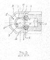
- the distributor assembly 100 comprises at least one squeegees 4, 6, and preferably due squeegees 4, 6 positioned adjacent to the contacting roll 7 and in particular positioned parallel to each other and with the contacting roll 7.
- the squeegees 4, 6 are almost cylindrical elements, and each being provided with a own longitudinal axis, identified respectively with the reference numbers 3 and 8. Each squeegees 4, 6 being pivotable on the respective longitudinal axis 3, 8 parallel to the rotation axis 9 of the contacting roll 7. Considering that the squeegees 4, 6 rotate on the respective longitudinal axes 3 and 8, also such axes are configured as rotating axes.
- the contacting roll 7, the squeegees 4 and 6 and the vertical portion 1" of the body 1 of the distributor assembly 100 jointly delimit the collecting chamber 13 described above. It should be considered in figure 3 that, the melted glue moves orthogonally to the design, parallel to the contacting roll 7 and the squeegees 4 and 6.
- the squeegees 4 and 6 are not cylindrical, but they have a flat surface 17 interrupting the circular profile of the squeegees 4 and 6.
- Such flat surface 17 can also be defined flatting and it is obtainable, for example, by milling.
- the intersection between the flat surface 17 and the remaining part of the outer cylindrical surface of the squeegees 4 and 6 defines a corner 10, 11, which can be defined side or vertical corner. Based on the angular position of the squeegees 4 and 6, the related corner 10, 11 is at a corresponding distance from the outer surface of the contacting roll 7.
- the side corner 10, 11 is parallel to the rotation axis 9 of the contacting roll 7 and the longitudinal axis 3, 8 of the respective squeegees 4, 6.
- the corner 10, 11 is movable between a distal position and a proximal position with respect to the contacting roll 7, depending on the angular position of the respective squeegees 4, 6 on the related longitudinal axis 3, 8. Between the corner 10, 11 and the outer surface of the contacting roll 7 a gap or window, through which the melted glue passes, is therefore defined.
- the squeegees 4 and 6 can be rotated on the respective axes 3 and 8 according to a direction to close the gap, and preventing the leakage of melted glue from the collecting chamber 13, or they can be rotate on the respective axes 3 and 8 according to an opposed direction to open or reducing the gap, and allowing the leakage of melted glue from the collecting chamber 13, on the surface of the contacting roll 7.
- the contacting roll 7 rotates on the rotation axis 9, it brings on its surface a certain amount of melted glue depositing on the portion of the contacting roll 7 oriented within the collecting chamber 13.
- the thickness of the glue layer that actually remains on the outer surface of the contacting roll 7 corresponds to the width of the gap defined between the corner 10, 11 of the squeegees 4 and 6 and the outer surface of the contacting roll 7.
- the corners 10 and 11 therefore can act as spatulas holding in the amount of melted glue exceeding the desired limit in the collecting chamber 13.
- the activation of the squeegees 4 and 6 can be manual, for example by an operation through a manual adjustment of the angular position of each squeegees 4, 6 selectively, through an adjusting screw, or the squeegees can be controlled by one or more actuators or servo-controls, according to a selective way.
- the contacting roll 7 rotates counterclockwise, the first squeegee 4 is stationary in an opening position, corresponding to a gap, and therefore corresponding to a thickness of the melted glue layer, equal to 2-3 tenths of a millimeter, and the second squeegee 6 is stationary in a closure position, with the related corner 10 in flush or almost in flush against the side surface of the contacting roll 7.
- the melted glue possibly contaminated by material particles of the panel subjected to edgebanding, does not return in the collecting chamber 13, but is scraped from the surface of the contacting roll to fall in the collecting tray 2".
- the maximum opening position of the squeegees 4, 6 corresponds to a distance from the outer surface of the contacting roll 7 equal to about 1 mm.
- Reference 15 indicates the rotation direction of the squeegees 4 and 6 to obtain the above described configuration.
- the proposed solution allows to precisely adjusting, but at the same time easily and effectively, the thickness of the melted glue layer on the contacting roll 7, guaranteeing at the same time to avoid the fouling of the melted glue in the collecting chamber 13.
- a further advantage provided by the third described feature consists of avoiding the contacting roll to ruin: also in the hypothesis wherein, by mistake, the operator acts clumsily on the squeegees 4 and 6, and disruptive interference with the contacting roll 7 is never created. This result is particularly obtained taking care of positioning the squeegees 4 and 6 with the related longitudinal axes 3 and 8 at the distance from the outer surface of the contacting roll not lower than the radius of the same squeegees 4 and 6, with a tolerance H/h7 according to standard UNI 6388 ISO R.286.
- the distance between the rotation axis 9 of the contacting roll 7 and the longitudinal axis 3 of the first squeegee 4 or the longitudinal axis 8 of the second squeegee 6, will be higher or equal to the outer sum of the outer radius of the contacting roll 7 and the radius of the squeegees 4 and 6, with tolerance H/h7. Therefore, the corner 10, 11 can at the limit be in flush on the surface of the contacting roll 7, to avoid the leakage of the melted glue, without having the possibility to practice any pressure sufficient to damage the knurling or the surface finishing of the contacting roll 7.
- the surface 17 can also be concave, or however can have a non-flat geometry, provided that its extending does not create any interference between the respective squeegees 4, 6 and the contacting roll 7.
- a third method of edgebanding according to the present invention therefore provides adjusting the thickness of the melted glue layer present on the outer surface of the contacting roll, acting on the squeegees 4, 6, and in particular and modifying the angular position thereof, rotating the squeegees 4, 6 on the respective longitudinal axes 3, 8, parallel to the contacting roll 7.
- the third method provides rotating the squeegees 4, 6 to correspondingly modify the orientation of the flat portion 17, and in particular the position of the corner 10, 11, and blocking the squeegees 4, 6 in the desired position, univocally corresponding to the width desiderata of the interstice present between the outer surface of the contacting roll 7 and each squeegees 4, 6; such interstice, being selectively settable for each squeegees 4, 6, defines the width of the melted glue layer that can leave the collecting chamber 13 and depositing on the outer surface of the contacting roll 7.
- a fourth feature of the distributor assembly 100 for which the Applicant reserves the possibility to file a divisional patent application, relates to a precaution which allows to effectively adjust the vertical extending of the melted glue layer deposited on the contacting roll 7, varying the thickness of the panels to be edgeboarded, between one batch and another batch.
- the sites 25 of the squeegees 4 and 6 are holes passing through the body 1 of the distributor assembly 100, in particular passing through le horizontal portions 1' of the body 1.
- the vertical sliding and the block of the squeegees 4 and 6 can be performed manually, by means for example of screw-elements, or each squeegees 4 and 6 can be equipped with of an actuator exactly configured for this purpose.
- the flat surface 17 of the squeegees 4 and 6 ends at the top with a corner 16, i.e. a step, which can be defined as higher corner 16.
- a corner 16 i.e. a step, which can be defined as higher corner 16.
- the corner or step 16 delimits at the top the extension of the melted glue layer, which can leave the collecting chamber 13.
- the vertical position of the corner 16 is also adjustable, i.e. determined by the operator depending on the need.
- the position of the corner 10, 11 of the flat surface 17 of the squeegees 4 and 6 defines, together with the outer surface of the contacting roll 7 the thickness of the glue layer.
- the higher corner 16 is twisted with respect to the longitudinal axis 3, 8 of the respective squeegees 4, 6.
- the lower limit of the flat surface 17 of the squeegees 4, 6 is defined by a seal element, also indicated as flap, 24 having, in transversal section, a shape which is complementary to the section of the respective squeegees 4, 6, or it can complete the circumference thereof.
- the shape of the flap 24 corresponds to the squeegee 4 or 6 portion eliminated to create the flat surface 17.
- the flaps 24 are visible also in figure 6 showing the distributor assembly 100 in a flat view, from the bottom.
- the flaps 24 are constrained to the body 1 of the distributor assembly 100 by means of a fastening element di 26 holding the flaps 24 however leaving a free-grade, i.e. the flaps 24 have the possibility to rotate together with the respective squeegees 4, 6.
- the element di fastening 26 is a guide inserting in a sliding way in an undercut of the flaps 24.
- the flaps 24 are provided with a corner or step 16' equivalent to corner/step 16 described above, and indicated as lower corner 16'.
- the corner or step 16' prevent the melted glue to color along the squeegees 4 and 6 through the holes 25 constituting the sites of the body 1 where the squeegees 4 and 6 rotate and move. This feature allows to maintaining clean the distributor assembly 100 in the lower part thereof.
- a for the method of edgebanding according to the present invention therefore provides adjusting the height of the melted glue layer present on the outer surface of the contacting roll, acting on the squeegees 4, 6, and in particular modifying the vertical position, i.e. the portion.
- the fourth method provides to lifting or lowering the squeegees 4, 6 in the respective sites of the body 1 of the distributor assembly 100, to modify the corresponding portion of the flat portion 17, and in particular the position of the higher corner 16, and blocking the squeegees 4, 6 in the desired position, univocally corresponding to the desired height desiderata of the interstice present between the outer surface of the contacting roll 7 and each squeegees 4, 6; such interstice, selectively configurable for each squeegees 4, 6, defines the height of the melted glue layer which can leave the collecting chamber 13 and depositing on the outer surface of the contacting roll 7. In fact, said height is determined from the distance between the higher corner 16 of the flat surface 17 and the lower corner 16' present on the seal element, or flap 25, closing at the bottom the flat surface 17 e, in general, the corresponding squeegees 4, 6.
- the fourth method can be carried out alternatively or jointly to the third method.
- the angular position of the flat surface 17 defines the thickness of the melted glue layer leaving the collecting chamber 13 on the outer surface of the contacting roll, and the vertical position, or height, of the flat surface 17 defines the height of the melted glue layer, i.e. the extension in a direction parallel to the rotation axis 9 of the contacting roll 7.
- the distributor assembly 100 is configurable by the user based on the thickness of the panels to be edgeboarded, and that can be performed selectively for each batch, even if the thickness changes from one batch to another. The operator can easily obtain the adjustment of the height of the melted glue layer applied to the contacting roll 7 adjusting the vertical position of the squeegees 4 and 6, as explained above.
- the squeegees 4, 6 can be removed from the top, along the related longitudinal axis, interchangeably, for their cleaning or replacing.
- a fifth feature of the distributor assembly 100 for which the Applicant reserves the possibility to file a divisional patent application, relates to a precaution allowing to constantly maintain clean melted glue deposited on the outer surface of the contacting roll 7.
- the outer surface of the contacting roll 7 has preferably an profile helicoidal, and more preferably helicoidal continuous, i.e. of the screw-type, alternatively to the conventional knurling or double knurling.
- This precaution allows to maintain clean the contacting roll 7, because it will be sufficient to equip the distributor assembly 100 with a comb-type scraper of a complementary form with respect to the profile of the contacting roll: thus, glue accumulations on the contacting roll 7 will be avoided.
- the helicoidal profile of the outer surface of the contacting roll 7 allows the particles of panel materials, possibly incorporated in the glue not-detached from the contacting roll 7, to accumulate at the higher or lower ends of the contacting roll 7, based on the rotation directions provided by motor M, which can be clockwise or counterclockwise AO, and depending on the direction of the profile helix.
- the contacting roll 7 with the helicoidal profile outer surface can be defined as self-cleaning, precisely because the particles thrusted upwards or downwards, but do not remain in the zone of the contacting roll 7 intended to roll on the panel edge to be edgeboarded.
- the solid particles possibly detached from the panels and incorporated in the glue present on the contacting roll 7, tend to accumulate to the higher end or to the lower end of the contacting roll 7, where the removal of the excess glue will be easy, for example with manual interventions, by scrapers. In any case, particles are removed and they does not more represent a drawback referring to the fouling of glue and panels under processing.
- a fifth method of edgebanding provides maintaining clean the outer surface of the contacting roll 7 making the same contacting roll 7 with profile helicoidal or screw outer surface, and not with the conventional knurling.
- the helicoidal outer surface promotes the automatic elimination of the undesired particles, which due to the rotation of the contacting roll 7, are thrusted towards the higher end or the lower end of the roll.
- the distributor body 100 has a generic C-shape; however this is not the sole shape possible: for example, the body C can be made with a cylindrical shape, with the collecting chamber 13 coaxial and external with respect to the mixing chamber 7' and the contacting roll 7.
- the present invention also relates to the following points, for each of which the Applicant reserves the possibility to file a divisional patent application.
Landscapes
- Life Sciences & Earth Sciences (AREA)
- Engineering & Computer Science (AREA)
- Mechanical Engineering (AREA)
- Wood Science & Technology (AREA)
- Forests & Forestry (AREA)
- Coating Apparatus (AREA)
- Adhesives Or Adhesive Processes (AREA)
- Rolls And Other Rotary Bodies (AREA)
Abstract
Description
- The present invention refers to a glue distributor assembly, associable to the edgebanding machine, and a method to carry out panel edgebanding.
- Wood panels, solid wood or derivatives thereof, for example chipboard or also plastic material, are used to manufature furnitures, shelving units, shelves and they are generally manufactured with two opposed flat faces and with an edge which is perpendicular to faces.
- The two faces of the raw panels are covered with a foil of ennobled material in suitable processing centers, in order to obtain the desired surface finishing and appearance, wherein such foils can have various colors, appearance, finishing and finishings. Once the two faces of a panel were ennobled, panels are subjected to an operation of edgebanding.
- In the wood processing industry the edgebanding machines has the function of applying a tape finishing element on the panel edge under processing, such that to ennobling also the panel edge. The tape finishing element can also be defined as profile, listel or strip, and it is commonly made of synthetic material.
- For the sake of simplicity, hereinafter, the tape finishing element will be named profile, or finishing profile, or edge profile.
- In the edgebanding machine, the finishing profiles are glued on the corresponding panel edge, remaining raw after the ennobling of the two faces of the panel. The finishing profile is usually applied as protruding: the profile has a width higher than the one of the panel board to which it is glued, in order to be sure to obtain a perfect covering of the edge and, in general, of the panel.
- Therefore, in order to obtain the finished panel, it is necessary to remove the exceeding part of the finishing profile, i.e. it is necessary to cut the profile to panel board size, both longitudinally, and transversally, i.e. in length and height. The splicing is an operation through which the finishing profile is cut to the same length of the panel board; the subsequent trimming operation involves the removal of the higher and lower portions of the finishing profile transversally protruding from the panel edge, beyond the faces. The splicing and the trimming are respectively carried out by specific splicing and trimming assembly, respectively; the first moving for a certain period of time together with the panel under processing, i.e. they move jointly to the panels for the time necessary to cut the part of the finishing profile exceeding in length, the second being stationary and carrying out the trimming taking advantage of the panel movement advancing in the edgebanding machine.
- The panel thus processed is then finished with the removal of processing waste and residues, by scrapers and brushes.
- The same operations described above for plate-edge panels are also carried out on panels with beveled edges; in this case the edgebanding machine will be equipped with molded tools in a substantially complementary way with respect to the panel edge.
- The following documents, in the name of SCM Group, describe edgebanding machine or components thereof:
EP 1997597 ,EP 2251165 ,EP 2062706 ,EP 2052822 ,EP 1785243 ,EP 1588812 ,EP 1464470 ,EP 0945235 ,EP1260277 . - An object of the present invention is a glue distributor assembly, or more simply a distributor assembly, intended to be installed on a edgebanding machine in order to allow a precise and effective glue application on the panel edge to be ennobled with the finishing profile, and / or in order to allow the precise and effective glue application on the same profile.
- A typical distributor assembly comprises a contacting roll, generally metallic and knurled, configurable to roll on the panel edge, or on the finishing profile, and releasing a glue amount on the related surface, which is sufficient to guarantee the right fastening of the profile on the panel edge. The contacting roll is motorized and the related rotation axis is maintained parallel to the surface of the panel edge under processing, or the surface of the finishing profile to be glued.
- The distributor assembly further comprises a heated tank, since the glue commonly used is of the thermal fuse polyurethane-type (PU, PUR, HMPUR), i.e. a glue with a relatively high melting temperature, usually included between 100°C and 140°C, which is to be hot-applied, being liquid, and cross-linking by reaction of isocyanate groups with the air humidity resulting in three-dimensional polyethers and / or polyurethane polyesters, comprising ureic bonds. Alternatively, glues containing ethylene vinyl acetate (EVA)-based thermoplastic resins are used, the latter also being hot-applied.
- At least one squeegee is arranged adjacent to the contacting roll, or a blade or a distributing blade-function element which together with the contacting roll defines the useful section for the glue passage towards the panel edge under processing.
- The glue is suitably distributed from the related container to the contacting roll surface, and then being distributed on the panel edge or on the finishing profile, before these two elements are pressed against one another in the edgebanding machine. The thickness of the glue layer deposited on the panel edge depends, as anticipated above, on the interstice defined between the squeegee, or the squeegees when more than one, and the contacting roll. Such thickness is adjustable, involving the possibility to adjust, i.e. precisely adjusting the position of the squeegee or squeegees with respect to the contacting roll.
- The glue distributor assemblies today available have some limits.
- A first limit relates to the maintenance of glue distributor assemblies. In the solutions today available, the cleaning of the contacting roll is complex, since it is not easy when the distributor assembly is assembled on the edgebanding machine, and a complete disassembly of the distributor assembly, i.e. its removal from the edgebanding machine and disassembly, is often necessary to obtain a deep cleaning. Obviously, the disassembly of the distributor assembly requires a machine downtown, during which the edgebanding machine cannot operate.
- A second limit consists in that, the glue firstly contained in the related tank, and then fed to the contacting roll, can be homogeneous: due to the fact that the temperature distribution between the inner surface of the tank, the outer surface of the contacting roll and the squeegee outer surface can be uniform, over the time the glue can have a different viscosity between one point and another of the distributor assembly and, in the worst case, clumps can be formed or it can locally crosslink.
- A third limit consists in that, the squeegees can damage the contacting roll surface when, during the maintenance operation, are brought to limit stop, in the position of minimum distance from the contacting roll. This case can be critical, since the squeegees can contact the surface of the contacting roll and damaging it if applied with high pressure. On the other side, there is a persistent need to nullify the glue passage section, i.e. there is the need for the user, during some operations of maintenance or testing, or fine-tuning of the edgebanding machine, to use the squeegees as barrier to completely intercept the glue passage and preventing the glue to reach the panel.
- A forth limit relates to the thickness variability of panels to be edgebanded and, accordingly, the finishing profiles height: based on the production batch, the panels can have an higher or lower thickness, or can change the height of the panel edge, for example 1.5 cm for a batch and 2 cm for another batch. In this case, the known distributor assemblies showed to be not very versatile, i.e. not very adaptable, resulting in that, glue distribution is often not optimal, with a dispersion beyond the panel edge, on the related faces, or with an insufficient distribution on the panel edge. In the first case, the results are the excessive fouling of panel faces, and in the second case the consequence is that the adhesion of the finishing profile to the corresponding panel edge is not perfect.
- A fifth limit consists is the tendency of the knurled contacting roll tends to hold wood particles detaching from the edge during panel edgebanding. The reason of such phenomenon is mostly due to the double knurling of the contacting roll, right and left, and it defines small rhomboid recesses in which over time, i.e. with the increasing number of edgebanded panels, the accumulated detached particles, are incorporated into the glue and thus affecting the contacting roll.
- Therefore, a first object of the present invention is to provide a glue distributor assembly which simply and effectively the limits of the solutions today available.
- Therefore, a first aspect of the present invention relates to a glue distributor assembly according to
claim 1, for edgebanding machine. - Particularly, the distributor assembly, comprises a body provided with a melted glue collecting chamber, and a contacting roll, pivotally supported on the body. The collecting chamber of the melted glue can be defined within the body, or it can be external to the body and constrainable to it, such as an outer tank. The outer surface of the contacting roll is intended for rolling on a panel edge to be edgebanded, or on a panel finishing profile, to distribute the melted glue collected from the collecting chamber and allowing panels ennoblement.
- Advantageously, the contacting roll is hollow and delimits an inner volume which is connected to the collecting chamber and in use it is crossed by the melted glue.
- Practically, the contacting roll has not only the function of distributing the melted glue on the panel edge to be edgebanded, or on the finishing profiles, also being part of a slow circuit of the melted glue, and this feature allows to uniformed temperature distribution in the distributor assembly. Having the possibility to recirculate, continuously or at time intervals, the melted glue in a specific distributor assembly circuit allows to solve the second drawback described with specific reference to the known solutions, that allows to avoid non-uniformity in the melted glue mass, in particular temperature non-uniformity. This result, in turn, allows to limit or completely preventing clumps formation in the glue, or the crosslinking in glue. Therefore, the proposed solution provides an improvement in the distributor assembly operation, which provides an improved gluing quality, reduced cleaning of the distributor assembly and, accordingly, reduced downtimes of the edgebanding machine.
- In the case wherein the glue collecting chamber is external to the body, it is connected to the flowing circuit through at least a specific connection; alternatively, and preferably, the collecting chamber is directly defined within the distributor assembly body.
- Preferably, the role of the inner volume of the contacting roll is not limited to the passage of the glue: in the preferred embodiment, the melted glue is subjected to a mixing within the contacting roll, continuous or according to time intervals. In other words, the inner volume of the contacting roll is configurable as a mixing chamber of the melted glue, arranged in fluid communication with the collecting chamber within the body.
- This expedient allows to maximize the above-described advantages, meaning that the mixing of the melted glue minimizes the risk of glue clotting or crosslinking.
- The mixing of the melted glue within the contacting roll can be obtained through several modes.
- A first mode involves making, above the inner surface, one or more projections, or ribs, so that after the rotation of the contacting roll on their rotation axis the projections, or ribs, provide a thrust on the melted glue, along the contacting roll.
- A second mode, which can be implemented alternatively or in addition to the first just described, consists of providing the distributor assembly of a mixing element inserted within the contacting roll. The mixing element is pivotable with respect to the contacting roll, and the relative rotation between the mixing element and the melted glue present in the contacting roll generates a thrust on the melted glue along the contacting roll.
- Clearly, the rotation direction of the contacting roll and the mixing element possibly positioned within defines the direction of the thrust on the melted glue, vertical ascending or vertical descending.
- Preferably the projections or ribs, and the mixing element, substantially extending as screw, or helix, or double helix.
- In the case wherein the mixing element is inserted in the contacting roll, it is coaxial to the roll and the projections or ribs.
- In the preferred embodiment, the collecting chamber extends in the body parallel to the contacting roll, and arranged in fluid communication with the inner volume of the contacting roll, at the ends of the contacting roll.
- Preferably, the distributor assembly comprises a top pivot and a lower pivot, and the contacting roll is supported on the body by these pivots, which are at least partially inserted in a corresponding end of the contacting roll. At least one between the top pivot and the lower pivot, and preferably both, is/are removable and the removal of the pivot, or pivots, releases the contacting roll from the body, for the disassembly.
- The coupling described above is advantageous since it allows the contacting roll to be assembled on the distributor assembly body, and disassembling the contacting roll from the body, in a simple and rapid manner, without necessarily dismounting the body or removing it from the edgebanding machine, missing the tolerances previously registered. In fact, in order to obtain the cleaning of the contacting roll, or for the substitution thereof, it will be sufficient removing a pivot, or both the pivots, in order to be able to remove the contacting roll from the body, without acting on the body itself.
- In this embodiment the pivots are preferably provided with at least a radial opening allowing the passage of the glue from the inner volume of the contacting roll, i.e. from the mixing chamber, to the collecting chamber, and vice versa.
- According to an embodiment, the distributor assembly has a through hole extending between an inlet, accessible to the outside of the distributor assembly, and an inner outlet al distributor assembly, by injection of a dye within the distributor assembly. Preferably the inner outlet of said through hole is arranged in correspondence of the contacting roll or the collecting chamber. Alternatively, the injection of the dye is carried out arranging a specific valve on the body of the distributor assembly providing an access to the melted-glue collecting inner chamber, or furthermore, arranging suitable injection means in the collecting chamber when the latter being external to the body.
- Providing the possibility to inject the dye in the distributor assembly, and particularly in the mixing chamber, where the mixing element is present, advantageously allows to obtain a rapid color change of the melted glue color and, especially, a uniform change of all the mass of melted glue present in the flow circuit, rapidly. In fact, the mixing element can be activated to vigorously mix the melted glue and obtaining a uniform dye distribution.
- The present invention also relates a method, according to
claim 16, for the panel edgebanding. The method comprises: - feeding a panel to a edgebanding machine equipped with a glue distributor assembly, provided with a body, an melting glue collecting chamber, outer or inner, and a contacting roll pivotally supported on the body and externally sprinkled with melted glue collected from the collecting chamber;
- Through the contacting roll, distributing melted glue on a panel edge to be edgebanded, or on a finishing profile intended to be glued on the panel edge, thus rolling the outer surface of the contacting roll on the panel edge or on the finishing profile.
- Advantageously, the method also provides arranging the hollow contacting roll and allowing the melted glue to flow from the collecting chamber through the contacting roll, and vice versa, in order to obtain the above described advantages with respect to the distributor assembly.
- According to a second aspect of the present invention, for which the Applicant reserves the possibility to file a divisional patent application, concerning an optional adjusting element of the same thickness of the melted glue layer adherent to the outer surface of the contacting roll.
- Hereinafter, such adjusting element will be named squeegee.
- The squeegee is substantially cylindrical and is housed in the body of the distributor assembly, parallel to the contacting roll and it is functionally interposed, with glue barrier function, between the outer surface of the contacting roll and the glue collecting chamber. Preferably, the squeegees are two. Each squeegee has a flat surface, or flatting, or slot, for example obtained by milling an outer surface portion, defining a side corner of the squeegee.
- Each squeegee is pivotable on its own longitudinal axis, which is parallel to the rotation axis of the contacting roll, and the side corner is accordingly movable between:
- a proximal position, in correspondence to which, the side corner is at the minimum distance from the outer surface of the contacting roll, and possibly in flush with it, and the thickness of the glue layer that can leave the collecting chamber and depositing on the contacting roll through the interstice defined by the side corner and from the contacting roll itself is minimum, for example 1-2 hundredths of a millimeter, and possibly null, and
- a distal position, in correspondence of which the side corner is at the maximum distance of the external surface of the contacting roll, for example 1 mm, and the thickness of the glue layer that can leave the collecting chamber and depositing on the contacting roll through the interstice defined by the side corner and the contacting roll itself is maximum, for example 1 mm.
- In an intermediate angular position of the squeegees, the interstice created between the side corner and the outer surface of the contacting roll, and therefore the thickness of the melted glue on the contacting roll, is from 2-3 tenths of a millimeter.
- Preferably le squeegees are pivotable on the respective longitudinal axes selectively and independent from each other. The activation can be manual, motorized or servo-assisted, and the squeegees can be blocked in the desired angular position.
- The proposed solution allows to effectively adjust, and without malfunctioning risks, the thickness of the glue layer on the contacting roll.
- Preferably the contacting roll is pivotable with respect to the rotation axis and each squeegee is pivotally on the longitudinal axes thereof, parallel to the rotation axis of the contacting roll. The longitudinal axis of each squeegee is at a distance from the rotation axis of the contacting roll corresponding to the sum of the outer radii of the contacting roll and of the squeegee, with a tolerance H/h7. This precaution allows to avoid that a mechanical interference occurs between the squeegees and the contacting roll, and jamming that could cause ruptures.
- According to a second aspect of the present invention relates also to a method, the second point 36, for the panel edgebanding. II method comprises:
- feeding a panel to an edgebanding machine equipped with a glue distributor assembly, provided with a body, a melted glue collecting chamber, a contacting roll pivotally supported on the body and externally sprinkled with melted glue collected from the collecting chamber, and at least one substantially cylindrical squeegee, functionally interposed between the collecting chamber and the contacting roll to adjust the amount of melted glue leaving from the collecting chamber directed towards the contacting roll;
- by the contacting roll, distributing the melted glue on an edge to be to be edgeboarded of the panel, or on a finishing profile intended to be glued on the panel edge, the outer surface of the contacting roll is allowed to rotate son the panel edge or the finishing profile.
- Advantageously, the method also provides:
- obtaining on the at least one squeegee a flat surface with a side corner, wherein through the interstice delimited from by the outer surface of the contacting roll and the flat surface the melted glue passage occurs, and
- adjusting the thickness of the glue layer released on the contacting roll rotating the at least one squeegee on its own longitudinal axis, parallel to the contacting roll, to correspondingly adjust the distance between the outer surface of the contacting roll and the side corner.
- The advantages of this method are the same described above in relation to the distributor assembly provided with squeegees with side corner, adjustable angularly.
- A third aspect of the present invention, for which the Applicant reserves the possibility to file a divisional patent application, concerns the following optional element optional for the height regulation of the melted glue layer adherent to the outer surface of the contacting roll, where the terms height refers to the extension of the glue layer parallel to the rotation axis of the contacting roll, i.e. parallel to the outer surface of the contacting roll.
- Such adjusting element is even a squeegee, i.e. a cylindrical element, housed in the body parallel to the contacting roll and functionally interposed, with a glue barrier function, between the outer surface of the contacting roll and the glue collecting chamber. Preferably the squeegees are two. Each squeegee has a flat surface, or flatting, e.g. obtained by milling a portion of the outer surface of the squeegee, defining a higher corner of the squeegee. Each squeegee is sliding with respect to the contacting roll, on its own longitudinal axis, and the higher corner is accordingly movable between:
- a maximum height position, in correspondence of which the height of the glue layer which can leave the collecting chamber and depositing on the contacting roll through the interstice defined by the squeegee and the contacting roll itself is maximum, for example equal to 15 mm, e
- a minimum height position a minimum height position , in correspondence of which the height of the glue layer which can leave the collecting chamber and depositing on contacting roll through the interstice defined by the squeegee and by the contacting roll itself is minimum, for example equal to 8 mm.
- The proposed solution allows to effectively adjust, and without risks of malfunctioning, the height of the glue layer on the contacting roll.
- Preferably the squeegees are movable along the respective longitudinal axes, for example moving, selectively and independently from each other. The activation can be manual, motorized or servo-assisted, and the squeegees can be blocked in the desired vertical position.
- The present invention is preferably implemented with two squeegee pivotable and sliding on the respective longitudinal axes and provided with both side corner, for adjusting the thickness of the melted glue layer released on the contacting roll, and the higher of the higher corner, for adjusting the height of the melted glue layer released on the contacting roll.
- Preferably the distributor assembly comprises, for each squeegee, a seal element, or flap, arranged in the body, in correspondence of the lower end of the respective squeegee, defining a lower corner of the flat surface described above and prevents the leakage of the melted glue from the bottom, i.e. it prevents the that melted glue can pour along the squeegee and leaking from the from the body of the distributor assembly. The squeegee being sliding with respect to the seal element thereof to adjust the distance between the higher corner and the lower corner and adjusting, accordingly, the height of the melted glue layer on the contacting roll.
- Preferably the seal element, or flap, is constrained to the body and it is blocked against the longitudinal movements against the longitudinal movements.
- The third aspect of the present invention also relates to a method, according to point 37, for the panel edgebanding, comprising:
- feeding a panel to an edgebanding machine equipped with a glue distributor assembly, provided with a body, a melted glue collecting chamber, a contacting roll pivotally supported on the body and externally sprinkled with melted glue collected from the collecting chamber, and at least one substantially cylindrical squeegee, functionally interposed between the collecting chamber and the contacting roll to adjust the amount of melted glue leaving from the collecting chamber directed towards the contacting roll;
- by the contacting roll, distributing the melted glue on an edge to be edgeboarded of the panel, or on a finishing profile intended to be glued on the panel edge, allowing the rolling of the outer surface of the contacting roll on the panel edge or on the finishing profile.
- Advantageously, the method also provides:
- obtaining on the at least one squeegee a flat surface with one higher corner, wherein through the interstice delimited by the outer surface of the contacting roll and la flat surface the passage of the melted glue occur, and
- adjusting the height of the glue layer released on the roll moving the least one squeegee on its own longitudinal axis, parallel to the contacting roll, to correspondingly adjust the portion of the higher corner.
- The advantages of this method are the same described above relating to relating the distributor assembly provided with squeegees with higher corner, adjustable vertically.
- A for the aspect of the present invention, for which the Applicant reserves the possibility to file a divisional patent application, relates to the coupling removable, and interchangeable, of the contacting roll on the body of the distributor assembly, obtained through a fastening element of the ends of the contacting roll of which at least one is removable. As described above, such fastening element are preferably pivots, one higher and one lower to, respectively, constrain the higher end and the lower end of the contacting roll to the body of the distributor assembly.
- Having removable fastening element allows to remove the contacting roll from the body of the distributor assembly, and assembly it again, in a short time, in a simple way and without necessarily disassembling or shifting the body of the distributor assembly.
- Preferably the fastening element, substantially the pivots, are at least partially hollow and they are part of the flow circuit of the melted glue, meaning that they define a part of the circuit formed by the inner volume of the contacting roll and the collecting chamber of the body.
- Preferably, the pivots have one or more radial openings exactly to allow the passage of the melted glue from the contacting roll to the collecting chamber, and vice versa.
- The fourth aspect of the present invention also relates to a method, according to point 39, for the panel edgebanding, comprising:
- feeding a panel to an edgebanding machine equipped with a glue distributor assembly, provided with a body, a melted glue collecting chamber, a contacting roll pivotally supported on the body and externally sprinkled with melted glue collected from the collecting chamber;
- by the contacting roll, distributing melted glue on an edge to be edgeboarded of the panel, or on a finishing profile intended to be glued on the panel edge, allowing the outer surface of the contacting roll to roll on the panel edge or on the finishing profile.
- Advantageously, the method also comprises:
- constraining the contacting roll to the body of the distributor assembly at the ends thereof, by respective fastening element, wherein at least one of the fastening element is removable to allow the disassembly of the contacting roll from the body by maintenance or replacing, without requiring the disassembly of the body.
- A fifth element of the present invention, for which the Applicant reserves the possibility to file a divisional patent application, related to the following optional feature: in the preferred embodiment the contacting roll does not have an outer surface with knurling or double knurling, but its outer surface has a continuous helicoidal profile. This precaution allows to promote the migration to the ends of the contacting roll di possible solid particles - initially detached from the panels subjected to edgebanding - present on the outer surface of the same contacting roll or incorporated in the glue. In this way, the formation of glue clumps and solid particles or mixtures is limited or completely prevented.
- The above described features is also object of point 40, and correspond to make self-cleaning the contacting roll with respect to the undesired solid particles.
- Further characteristics and advantages of the invention will be better highlighted by examining the following detailed description of a preferred embodiment, but not exclusive, according to an illustrative, but not limiting, purpose, by means of the finishing enclosures, wherein:
-
figure 1 is a front isometric view of a glue distributor assembly according to the present invention; -
figure 2 is a vertical section view, considered on the median plane B-B showed infigure 1 ; -
figure 3 is an horizontal section view, considered on the plane A-A showed infigure 1 ; -
figure 4 is a rear perspective view of the glue distributor assembly showed infigure 1 ; -
figure 5 è an elevation view and partially enlarged of a component of the glue distributor assembly showed infigure 1 ; -
figure 6 is a plane view and from the bottom of the glue distributor assembly showed infigure 1 . - The attached figures show the preferred embodiment of the
glue distributor assembly 100 according to the present invention, hereinafter briefly indicated as distributor assembly. - The
distributor assembly 100 comprises abody 1 supporting the other components. Thebody 1, preferably metallic, has a general C-shape C, i.e. it has two horizontal portions ha due horizontal portions 1' joined by avertical portion 1". Between the horizontal portions 1' a contactingroll 7 is supported, whoserotation axis 9 is vertical, i.e. parallel to thevertical portion 1" of thebody 1. The contactingroll 7 is intended to constrain by rolling the edge of a panel to be edgeboarded with the finishing profile (not showed), in order to apply on such edge a glue layer sufficient to guarantee the adhesion of a finishing profile, as described below. - The contacting
roll 7 is pivotally assembled on thebody 1 and it is motorized. The rotation speed, or rpm, are selected such that between the rotating contactingroll 7 and the panels to be edgeboarded, moving on the edgebanding machine, slipping do not occur. - A first advantageous feature of the
distributor assembly 100, for which the Applicant reserves the possibility to file a divisional patent application, consist in the fact that the contactingroll 7 is easily removable from thebody 1 of thedistributor assembly 100, in a substantially interchangeable way. - This result is obtained, as showed as best as possible in
figure 2 , constraining the contactingroll 7 to thebody 1 at the ends thereof, withfastening elements - Preferably, the fastening means are a
top pivot 18 and alower pivot 19, which operate also as bushings for the pivotable support of the contactingroll 7. Thepivots body 1, coaxially with respect to therotation axis 9 of the contactingroll 7. At least one between thetop pivot 18 and thelower pivot 19, and preferably both, are removable from thebody 1 of thedistributor assembly 100 to allow the disassembly of the contactingroll 7. In other words, once thetop pivot 18 and thelower pivot 19 were removed from the respective horizontal portions 1' of thebody 1, the contactingroll 7 is laterally or frontally from thebody 1, simply with one hand. For example, thetop pivot 18 and thelower pivot 19 are inserted without any clearance, or with minimum tolerances, in corresponding sites 18' and 19' obtained in thebody 1 of thedistributor assembly 100 and blocked by Seager rings, pins or other mechanical fasteners. Alternatively, thetop pivot 18 and thelower pivot 19 are addressed to the respective sites 18' and 19'. - According to an embodiment, the relative rotation between the contacting roll and the
pivots inner surface 7 and thepivots - According to an alternative embodiment the contacting
roll 7 and thepivots body 1, for example supported by bushings or bearings. - Preferably, the inner diameter of the contacting
roll 7 has a first value at the central portion, and a second value which is higher than the first one at the end, such that thepivots roll 7 wired with the inner surface of the central portion, such that to define within the contacting roll 7 a perfectly cylindrical volume. - The coupling between the contacting
roll 7 and thebody 1 of thedistributor assembly 100 allows to solve the first described drawback relating to the prior art. In fact, due to the fact that the disassembly of the contactingroll 7 is easily obtainable by simply removing thetop pivot 18 and thelower pivot 19 from thebody 1, and removing the contactingroll 7, the cleaning and the maintenance of the contactingroll 7 are possible rapidly, in a simple way, as the reassembly. For the reassembly of the contactingroll 7 on thebody 1 it will be sufficient to carry out the operations inversely with respect to the disassembly: a mechanical maintenance technician will insert the contactingroll 7 in thebody 1, vertically along therotation axis 9, between the horizontal portions 1' and parallel to thevertical portion 1", and proceeding by inserting thepivots pivots body 1. - Clearly, it is possible to have a plurality of spare contact rolls 7, such that minimizing the length of the machine downtime: the mechanical maintenance technician will be able to simply replace the contacting
roll 7, as described above, with a clean roll and starting the edgebanding machine, in few minutes, having the possibility to calmly clean the contactingroll 7 previously collected. - The possibility to constantly maintain the contacting
roll 7 in good cleaning conditions allows to maximize the productivity and the quality of the edgebanding. - Preferably, as showed in
figures 1 and2 , thedistributor assembly 100 comprises aguard element 2 screwed to thebody 1 with screws 2', frontally at the lower horizontal portion 1'. Theguard element 2 protrudes beyond the higher edge of the lower horizontal portion 1' such that to delimit collectingtray 2" of the residual or excess glue, possibly casted from the contactingroll 7. Indeed, theguard element 2 guarantee that the contactingroll 7 cannot be disassembly from thebody 1 without having previously unscrewed and separated theguard element 2 itself. - A first method of edgebanding according to the present invention provides, therefore, the easy disassembly of the contacting
roll 7 from thebody 1, simply removing thepivots body 1. - Once pivots 18 and 19 are removed, the contacting
roll 7 is removable from the horizontal portions 1' of thebody 1 of thedistributor assembly 100, simply pulling with a hand. - The method also involves an easy reassembly of the contacting roll 7: it will be sufficient to reposition the contacting
roll 7 between the horizontal portions 1' of thebody 1, coaxially to therotation axis 9, and subsequently insertingpivots body 1. - A second advantageous feature of the
distributor assembly 100, for which the Applicant reserves the possibility to file a divisional patent application, is constituted by the fact that the contactingroll 7 is internally hollow, and the melted glue, i.e. maintained to a temperature higher to the related melting temperature, is allowed to flow and the melting glue is continuously mixed at the molten state, i.e. maintained at a temperature higher to the related melting temperature. - As better showed in
figure 2 , preferably also thetop pivot 18 and thelower pivot 19 are hollow, such that to allow the passage of the melted glue, and the inner volume of the contactingroll 7 delimits a mixing chamber 7' of the melted glue. The mixing chamber 7', is coaxial with respect to therotation axis 9, practically extending within the contactingroll 7, and also through thepivots chamber 13 of the melted glue, extending within thevertical portion 1" of thebody 1 of thedistributor assembly 100 along anaxis 27 parallel to therotation axis 9, such that the two chambers, i.e. the mixing chamber 7' and the collectingchamber 13 define a circuit for the melted glue flowing. Observingfigure 2 , the melted glue flowing can be counterclockwise (white arrow x) or clockwise (black arrow y), as described below, more in detail. The collectingchamber 13 is opened at the top in correspondence of an opening 27', closable by a cap, allowing to load new glue. - According to an alternative embodiment, the collecting
chamber 13 is external to thebody 1, for example positioned next to thebody 1, and connected to the mixing chamber 7' through a hole made in thebody 1 which allows the access to the flow circuit. - In the embodiment showed in the figures, the
top pivot 18 and thelower pivot 19 have each a radial opening, seefigure 2 , or they are laterally opened towards the collectingchamber 13, in order to allow the passage of the melted glue from and towards the collectingchamber 13 during the use of thedistributor assembly 100. - The glue is maintained to a temperature higher than the melting temperature from one or
more resistors 5 inserted in thebody 1 of thedistributor assembly 100. Theresistors 5 dissipate energy by Joule effect. - Preferably, within the contacting roll 7 a mixing
element 21, having the function of promoting the mixing and the movement of the melted glue, is housed. The mixingelement 21 can be made as a screw-element, or a cochlea, or as an helicoidal stirrer. In the example showed in the figure, and in particular infigure 2 , the mixing element extends from thetop pivot 18 up to thelower pivot 19, for the whole length of the contactingroll 7, resulting coaxial thereto. According to alternative embodiment, the mixingelement 21 is shorter than the contactingroll 7. - The flowing of the melted glue can be obtained according two modes, provided that a relative rotation, between the contacting
roll 7 and the mixingelement 21 housed within it, is obtained. - According to a first embodiment the contacting
roll 7 is motorized, i.e. it is connected to the crank shaft 20 of an electric motor M, directly as showed infigure 1 or indirectly by a transmission system, in such case, through friction between theinner surface 7 and the melted glue, an axial thrust is created, i.e. along therotation axis 9, depending on the helix direction of the mixingelement 21, resulting glue in that the glue is mixed and allowed to flow. - According to a second embodiment, in addition to the contacting
roll 7, the mixingelement 21 is motorized, this component being connected to the crank shaft 20 of an electric motor M, through thelower pivot 19. In this case, the mixingelement 21 directly thrusts axially the melted glue, mixing and allowed to flow. - When it is necessary to maintain the seal, and preventing melted glue leakages, O-ring seals are installed, for example between the
pivots body 1. - Alternatively, or in addition to the mixing
element 21, theinner surface 7 is provided with protruding ribs (not showed), for example helicoidally, thrust the melted glue upward or downward, according to the rotation directions, when the contactingroll 7 is thrust-rotation. The protruding ribs can have a continuous path, or can be interrupted and extending as circle arcs. - In other words, the mixing
element 21 can be used in combination with a contactingroll 7 provided with inner protruding ribs, suitably sized to avoid mechanical interferences. - The possibility of usually or continuously mixing the melted glue and allowing it to flow within the above-described circuit, allows to solve the second drawback described relating to the known solutions, i.e. allowing to avoid a non-uniformity in the mass of the melted glue, in particular temperature non-uniformity, as well as clumps or localized crosslinking and, in general, it allows to obtain results which are qualitatively higher and repeatable over time.
- In some applications, it is necessary to have available a glue of a certain color, typically a color matching with the color of the material used to ennoble panels.
- In order to satisfy such necessity, the
distributor assembly 100 is optionally provided with an injection system of a dye within the distributor assembly itself, in particular in the mixing chamber 7'. More in detail, the mixingelement 21 is provided on the top with at least ahole 22, seefigure 2 , axially extending between an inlet, which is showed in the example as funnel-shaped, and an outlet which opens in the mixing chamber 7' at one ormore doors 23; the operator can use thehole 22 to inject the concentrated dye, so as to change the color of the melted glue already present in the mixing chamber 7'. Advantageously, in this way the desired color of the melted glue can be obtained without empting the glue circuit to fill it with another glue of the desired color, and therefore maintaining constant the circuit temperature. The mixture of the melted glue obtained as described above guarantees the uniform chromatic tone of all the melted glue flowing in the circuit. - Alternatively, the dye injection can be performed involving a suitable valve on the
body 1 of thedistributor 100, providing access to the collectingchamber 13. - A second method of edgebanding according to the present invention involve, therefore, the melted glue flowing not only in the
inner collecting chamber 13 to thebody 1 of thedistributor assembly 100, but also through the contactingroll 7, which is hollow. More in detail, the method involve to make a flow circuit of the melted glue, arranging in flow communication the inner volume of the contactingroll 7 with the collectingchamber 13 of thebody 1. - Based on the rotation direction of the contacting roll, clockwise or counter clockwise, the thrust on the melted glue will be directed upwards or downwards.
- Preferably, the secondo method is implemented using a contacting roll internally shaped with the thrust surfaces, projections or ribs, for example at least helicoidally, and / or arranging in the contacting roll 7 a stirring
element 21, having a screw-, or helix- or double helix-extension, such that the contactingroll 7 has a cochlea function for the melted glue inside, i.e. such that the rotation causes the movement of the melted glue in the flow circuit. - The second method optionally involves to change the color of the melted glue color present in the flow circuit, injecting a dye by a through hole present in the stirring
element 21 described-above. - A third feature of the
distributor assembly 100, for which the Applicant reserves the possibility to file a divisional patent application, relates to a precaution which allows to effectively adjust the thickness of the glue layer deposited on the panel edge to be edgeboarded. - With reference to
figure 1 and3 , thedistributor assembly 100 comprises at least onesqueegees due squeegees roll 7 and in particular positioned parallel to each other and with the contactingroll 7. - As described below, the
squeegees reference numbers longitudinal axis rotation axis 9 of the contactingroll 7. Considering that thesqueegees longitudinal axes - With reference to
figure 3 , showing an horizontal section of thedistributor assembly 100, or a section considered on a plane orthogonal to the threerotating axis squeegees roll 7 and thevertical portion 1" of thebody 1, which is stationary. As observable, thesqueegees vertical portion 1" of thebody 1 of thedistributor assembly 100, wherein a gap is not defined within, such that between thesqueegees vertical portion 1" of the body 1 a passage of melted glue does not occur. - In other words, the contacting
roll 7, thesqueegees vertical portion 1" of thebody 1 of thedistributor assembly 100 jointly delimit the collectingchamber 13 described above. It should be considered infigure 3 that, the melted glue moves orthogonally to the design, parallel to the contactingroll 7 and thesqueegees - With reference to
figure 1 ,3 and4 , thesqueegees flat surface 17 interrupting the circular profile of thesqueegees flat surface 17 can also be defined flatting and it is obtainable, for example, by milling. The intersection between theflat surface 17 and the remaining part of the outer cylindrical surface of thesqueegees corner 10, 11, which can be defined side or vertical corner. Based on the angular position of thesqueegees related corner 10, 11 is at a corresponding distance from the outer surface of the contactingroll 7. - The
side corner 10, 11 is parallel to therotation axis 9 of the contactingroll 7 and thelongitudinal axis respective squeegees - In other words, the
corner 10, 11 is movable between a distal position and a proximal position with respect to the contactingroll 7, depending on the angular position of therespective squeegees longitudinal axis corner 10, 11 and the outer surface of the contacting roll 7 a gap or window, through which the melted glue passes, is therefore defined. Accordingly, thesqueegees respective axes chamber 13, or they can be rotate on therespective axes chamber 13, on the surface of the contactingroll 7. - Practically, when the contacting
roll 7 rotates on therotation axis 9, it brings on its surface a certain amount of melted glue depositing on the portion of the contactingroll 7 oriented within the collectingchamber 13. The thickness of the glue layer that actually remains on the outer surface of the contactingroll 7 corresponds to the width of the gap defined between thecorner 10, 11 of thesqueegees roll 7. Thecorners 10 and 11 therefore can act as spatulas holding in the amount of melted glue exceeding the desired limit in the collectingchamber 13. Closing thesqueegees respective axes corners 10, 11 wired to the outer surface of the contactingroll 7, practically at a distance of 2-3 hundredths of a millimeter, the leaving of the glue from the collectingchamber 13 is prevented, i.e. the containment function of the melted glue is performed, since substantially the whole is scraped and collected from the surface of the contactingroll 7. - The activation of the
squeegees squeegees - In the configuration showed in
figure 3 , the contactingroll 7 rotates counterclockwise, thefirst squeegee 4 is stationary in an opening position, corresponding to a gap, and therefore corresponding to a thickness of the melted glue layer, equal to 2-3 tenths of a millimeter, and thesecond squeegee 6 is stationary in a closure position, with the related corner 10 in flush or almost in flush against the side surface of the contactingroll 7. In this way, the melted glue possibly contaminated by material particles of the panel subjected to edgebanding, does not return in the collectingchamber 13, but is scraped from the surface of the contacting roll to fall in the collectingtray 2". - The maximum opening position of the
squeegees roll 7 equal to about 1 mm. -
Reference 15 indicates the rotation direction of thesqueegees - It is evident that reversing the rotation direction of the contacting
roll 7, it is sufficient to close thefirst squeegee 4 and opening thesecond squeegee 6 to obtain an effective result, or precisely adjusting the thickness of the melted glue layer on the contactingroll 7. - The proposed solution allows to precisely adjusting, but at the same time easily and effectively, the thickness of the melted glue layer on the contacting
roll 7, guaranteeing at the same time to avoid the fouling of the melted glue in the collectingchamber 13. - A further advantage provided by the third described feature consists of avoiding the contacting roll to ruin: also in the hypothesis wherein, by mistake, the operator acts clumsily on the
squeegees roll 7 is never created. This result is particularly obtained taking care of positioning thesqueegees longitudinal axes same squeegees rotation axis 9 of the contactingroll 7 and thelongitudinal axis 3 of thefirst squeegee 4 or thelongitudinal axis 8 of thesecond squeegee 6, will be higher or equal to the outer sum of the outer radius of the contactingroll 7 and the radius of thesqueegees corner 10, 11 can at the limit be in flush on the surface of the contactingroll 7, to avoid the leakage of the melted glue, without having the possibility to practice any pressure sufficient to damage the knurling or the surface finishing of the contactingroll 7. - Alternatively, the
surface 17 can also be concave, or however can have a non-flat geometry, provided that its extending does not create any interference between therespective squeegees roll 7. - A third method of edgebanding according to the present invention therefore provides adjusting the thickness of the melted glue layer present on the outer surface of the contacting roll, acting on the
squeegees squeegees longitudinal axes roll 7. - More in detail, the third method provides rotating the
squeegees flat portion 17, and in particular the position of thecorner 10, 11, and blocking thesqueegees roll 7 and eachsqueegees squeegees chamber 13 and depositing on the outer surface of the contactingroll 7. - A fourth feature of the
distributor assembly 100, for which the Applicant reserves the possibility to file a divisional patent application, relates to a precaution which allows to effectively adjust the vertical extending of the melted glue layer deposited on the contactingroll 7, varying the thickness of the panels to be edgeboarded, between one batch and another batch. - With particular reference to
figure 1 and4 , based on the production batch and, therefore, based on the thickness of panels to be edgebanded, it is desirable that the height of the melted glue layer deposited on the contactingroll 7 can be adjusted, i.e. the extension of the parallel layer to therotation axis 9. This result is obtained in thedistributor assembly 100 through the fact that thesqueegees respective sites 25 obtained in thebody 1, each squeegees 4, 6 being movable along the ownlongitudinal axis squeegee - Nin the example showed in the figures, the
sites 25 of thesqueegees body 1 of thedistributor assembly 100, in particular passing through le horizontal portions 1' of thebody 1. - The vertical sliding and the block of the
squeegees squeegees - As better showed in
figure 4 , theflat surface 17 of thesqueegees corner 16, i.e. a step, which can be defined ashigher corner 16. When thedistributor assembly 100 is operating, and the contactingroll 7 rotates on itsown rotation axis 9, collecting the melted glue from the collectingchamber 13, the corner or step 16 delimits at the top the extension of the melted glue layer, which can leave the collectingchamber 13. Clearly, considering that thesqueegees corner 16 is also adjustable, i.e. determined by the operator depending on the need. As described above, the position of thecorner 10, 11 of theflat surface 17 of thesqueegees roll 7 the thickness of the glue layer. - The
higher corner 16 is twisted with respect to thelongitudinal axis respective squeegees - Moving longitudinally the
squeegees arrow 28 from position A of maximum height of the melted glue layer, to the position B of minimum height of the melted glue layer, and blocking thesqueegees roll 7, seamless independently by the angular position of thesqueegees - The lower limit of the
flat surface 17 of thesqueegees respective squeegees flap 24 corresponds to thesqueegee flat surface 17. - The
flaps 24 are visible also infigure 6 showing thedistributor assembly 100 in a flat view, from the bottom. - The
flaps 24 are constrained to thebody 1 of thedistributor assembly 100 by means of a fastening element di 26 holding theflaps 24 however leaving a free-grade, i.e. theflaps 24 have the possibility to rotate together with therespective squeegees flaps 24. - At the bottom, the
flaps 24 are provided with a corner or step 16' equivalent to corner/step 16 described above, and indicated as lower corner 16'. The corner or step 16' prevent the melted glue to color along thesqueegees holes 25 constituting the sites of thebody 1 where thesqueegees distributor assembly 100 in the lower part thereof. - A for the method of edgebanding according to the present invention therefore provides adjusting the height of the melted glue layer present on the outer surface of the contacting roll, acting on the
squeegees - More in detail, the fourth method provides to lifting or lowering the
squeegees body 1 of thedistributor assembly 100, to modify the corresponding portion of theflat portion 17, and in particular the position of thehigher corner 16, and blocking thesqueegees roll 7 and eachsqueegees squeegees chamber 13 and depositing on the outer surface of the contactingroll 7. In fact, said height is determined from the distance between thehigher corner 16 of theflat surface 17 and the lower corner 16' present on the seal element, orflap 25, closing at the bottom the flat surface 17 e, in general, the correspondingsqueegees - The fourth method can be carried out alternatively or jointly to the third method.
- Ultimately, the angular position of the
flat surface 17 defines the thickness of the melted glue layer leaving the collectingchamber 13 on the outer surface of the contacting roll, and the vertical position, or height, of theflat surface 17 defines the height of the melted glue layer, i.e. the extension in a direction parallel to therotation axis 9 of the contactingroll 7. - The main advantage provided by the proposed solution is evident: the
distributor assembly 100 is configurable by the user based on the thickness of the panels to be edgeboarded, and that can be performed selectively for each batch, even if the thickness changes from one batch to another. The operator can easily obtain the adjustment of the height of the melted glue layer applied to the contactingroll 7 adjusting the vertical position of thesqueegees - According to one embodiment, the
squeegees squeegees body 1. - In the case wherein this solution is implemented together with the possibility, previously described, of adjusting the thickness of the glue layer, it can be understood as the
distributor assembly 100 is extremely versatile, giving to the operator the complete control of the geometrical characteristics of the melted glue layer. - A fifth feature of the
distributor assembly 100, for which the Applicant reserves the possibility to file a divisional patent application, relates to a precaution allowing to constantly maintain clean melted glue deposited on the outer surface of the contactingroll 7. - With particular reference to
figure 5 , the outer surface of the contactingroll 7 has preferably an profile helicoidal, and more preferably helicoidal continuous, i.e. of the screw-type, alternatively to the conventional knurling or double knurling. This precaution allows to maintain clean the contactingroll 7, because it will be sufficient to equip thedistributor assembly 100 with a comb-type scraper of a complementary form with respect to the profile of the contacting roll: thus, glue accumulations on the contactingroll 7 will be avoided. - However, even if a scraper is not used, the helicoidal profile of the outer surface of the contacting
roll 7 allows the particles of panel materials, possibly incorporated in the glue not-detached from the contactingroll 7, to accumulate at the higher or lower ends of the contactingroll 7, based on the rotation directions provided by motor M, which can be clockwise or counterclockwise AO, and depending on the direction of the profile helix. In this way, the contactingroll 7 with the helicoidal profile outer surface can be defined as self-cleaning, precisely because the particles thrusted upwards or downwards, but do not remain in the zone of the contactingroll 7 intended to roll on the panel edge to be edgeboarded. - Therefore, advantageously, considering a use of the
distributor assembly 100 for many hours per day, the solid particles possibly detached from the panels and incorporated in the glue present on the contactingroll 7, tend to accumulate to the higher end or to the lower end of the contactingroll 7, where the removal of the excess glue will be easy, for example with manual interventions, by scrapers. In any case, particles are removed and they does not more represent a drawback referring to the fouling of glue and panels under processing. - Therefore, a fifth method of edgebanding according to the present invention provides maintaining clean the outer surface of the contacting
roll 7 making the same contactingroll 7 with profile helicoidal or screw outer surface, and not with the conventional knurling. The helicoidal outer surface promotes the automatic elimination of the undesired particles, which due to the rotation of the contactingroll 7, are thrusted towards the higher end or the lower end of the roll. - In the attached figures, the
distributor body 100 has a generic C-shape; however this is not the sole shape possible: for example, the body C can be made with a cylindrical shape, with the collectingchamber 13 coaxial and external with respect to the mixing chamber 7' and the contactingroll 7. - The present invention also relates to the following points, for each of which the Applicant reserves the possibility to file a divisional patent application.
- 16. A glue distributor assembly (100) for edgebanding machine, comprising a body (1) provided with a collecting chamber (13) of melted glue, a contacting roll (7), pivotally supported on the body (1), and at least one substantially cylindrical squeegee (4, 6), functionally interposed between the collecting chamber (13) and the contacting roll (7) to adjust the amount of melted glue leaving from the collecting chamber (13) directed towards the contacting roll (7), wherein the outer surface of the contacting roll (7) is intended for rolling on a panel edge to be edgeboarded or on a panel finishing profile, to distribute the melted glue collected from the collecting chamber (13), characterized in that said squeegee (4, 6) is pivotable on a longitudinal axis thereof (3, 8), parallel to the contacting roll (7), and has a flat surface (17), or flatting, or slot, defining a side corner (10, 11) of the squeegee (4, 6) and the fact that the distance between the outer surface of the contacting roll (7) and the side corner (10, 11) is univocally determined from the angular position of the squeegee squeegee (4, 6) and corresponds to the thickness of the glue layer released on the roll (7).
- 17. Distributor assembly (100) according to
point 16, wherein the side corner (10, 11) is movable, in response to the rotations provided to the respective squeegee (4, 6) on the related longitudinal axis (3, 8), between a proximal position, corresponding to the minimum distance from the outer surface of the contacting roll (7), and corresponding to the minimum thickness of the glue layer released on the roll (7), and a distal position, corresponding to the maximum distance from the outer surface of the contacting roll (7), and corresponding to the maximum thickness of the glue layer released on the roll (7). - 18. Distributor assembly (100) according to
point 17, wherein la proximal position of the side corner (10, 11) corresponds to the corner in flush against the outer surface of the contacting roll (7), and corresponds to prevent the passage of melted glue from the collecting chamber (13) to the contacting roll (7). - 19. Distributor assembly (100) according to any one of the preceding points 16-18, comprising two squeegees (4, 6) supported on the body (1) pivotable sui respective longitudinal axes (3, 8) parallel to the rotation axis (9) of the contacting roll (7), wherein le squeegees (4, 6) intercept a corresponding passage present between the collecting chamber (13) and the contacting roll (7), and wherein the squeegees (4, 6) are selectively pivotable and they can be blocked in the desired position, independently from each other.
- 20. A glue distributor assembly (100) for edgebanding machine, comprising a body (1) provided with a collecting chamber (13) of melted glue, a contacting roll (7), pivotally supported on the body (1), and at least one substantially cylindrical squeegee (4, 6), functionally interposed between the collecting chamber (13) and the contacting roll (7) to adjust the amount of melted glue leaving from the collecting chamber (13) directed towards the contacting roll (7), wherein the outer surface of the contacting roll (7) is intended for rolling on a panel edge to be edgeboarded or on a panel finishing profile, to distribute the melted glue collected from the collecting chamber (13), characterized in that said squeegee (4, 6) is movable longitudinally along their own longitudinal axis (3, 8), parallel to the contacting roll (7), and has a flat surface (17), or flatting, or slot, defining a higher corner (16) of the squeegee (4, 6) and due the fact that the portion of the higher corner (16) is univocally determined by the longitudinal position of the squeegee (4, 6) and corresponds to the height of the glue layer released on the roll (7).
- 21. Distributor assembly (100) according to point 20, wherein the higher corner (16) is movable, in response to the longitudinal movements provided to the respective squeegee (4, 6) on the related longitudinal axis (3, 8), between a minimum height position, corresponding to the minimum height of the glue layer released on the roll (7), and a position of maximum height, corresponding to the maximum height of the glue layer released on the roll (7).
- 22. Distributor assembly (100) according to point 20 or
point 21, comprising a seal element (25), or flap, interposed between the body (1) and the respective squeegee (4, 6), to close at the bottom the opening defined between the flat surface (17) and the body (1), wherein the squeegee (4, 6) is sliding with respect to the corresponding seal element (25), and the seal element (25) comprises a lower corner (16') delimiting at the bottom the glue layer released on the roll (7). - 23. Distributor assembly (100) according to
point 22, wherein the seal element is constrained to the body (1) and is blocked against the longitudinal movements, and wherein the higher corner (16) is movable, in response to the longitudinal movements of the respective squeegee (4, 6), between a position od minimum distance from the lower corner (16'), corresponding to the minimum height of the glue layer released on the roll (7), and a position od maximum distance from the lower corner (16'), corresponding to the maximum height of the glue layer released on the roll (7). - 24. Distributor assembly (100) according to any one of the points 20-23, comprising due squeegees (4, 6) supported on the body (1) movable along the respective longitudinal axes (3, 8) parallel to the rotation axis (9) of the contacting roll (7), wherein le squeegees (4, 6) intercept a corresponding step present between the collecting chamber (13) and the contacting roll (7), and wherein the squeegees (4, 6) are selectively movable and they can be blocked in the desired longitudinal position, independently from each other.
- 25. Distributor assembly (100) according to any one of the points 20-24, wherein le squeegees (4, 6) have the characteristics described in any one of the points 16-19.
- 26. A glue distributor assembly (100) for edgebanding machine, comprising a body (1) provided with a collecting chamber (13) of melted glue, a contacting roll (7), pivotally supported on the body (1), wherein the outer surface of the contacting roll (7) is intended for rolling on a panel edge to be edgeboarded or on a panel finishing profile, to distribute the melted glue collected from the collecting chamber (13), characterized in that le ends of the contacting roll (7) are constrained to the body (1) by the corresponding fastening elements (18, 19) of which at least one is removable to allow the disassembly of the contacting roll (7) from the body (1).
- 27. Distributor assembly (100) according to
point 26, wherein the contacting roll (7) is hollow and the fastening elements (18, 19) are a top pivot (18) and a lower pivot (19), even these being hollow, and together with the contacting roll (7) define an inner volume that can be crossed by the melted glue. - 28. Distributor assembly (100) according to
point 26 orpoint 27, wherein the contacting roll (7) is hollow and the inner volume thereof is in a fluid communication with the collecting chamber (13), through the fastening elements (18, 19), and the inner volume of the contacting roll (7) and the collecting chamber (13) jointly defining a flow circuit of the melted glue. - 29. Distributor assembly (100) according to
point 27 orpoint 28, wherein the top pivot (18) and the lower pivot (19) have at least a radial opening in order to allow the fluid communication with the collecting chamber (13). - 30. Distributor assembly (100) according to any one of the points 26-29, wherein the inner surface (7) has one or more projections, or ribs, and / or the distributor assembly (100) comprises a mixing element (12) inserted within of the contacting roll (7) and pivotable thereto, and wherein la relative rotation between the projections or ribs and la melted glue present in the contacting roll (7), and la relative rotation between the mixing element (12) the melted glue present in the contacting roll (7), generate a thrust on the melted glue.
- 31. Distributor assembly (100) according to point 30, wherein said projections or ribs, and said mixing element (12), extending substantially as a screw, or an helix, or a double helix.
- 32. Distributor assembly (100) according to any one of the points 29-31, wherein the mixing element (12) has a through hole (22) extending between an inlet, accessible to the outside of the contacting roll (7), and an outlet within the contacting roll (7), for the injection of a dye within the contacting roll (7).
- 33. A glue distributor assembly (100) for edgebanding machine, comprising a body (1) provided with a collecting chamber (13) of melted glue, a contacting roll (7), pivotally supported on the body (1), wherein the outer surface of the contacting roll (7) is intended for rolling on a panel edge to be edgeboarded or on a panel finishing profile, to distribute the melted glue collected from the collecting chamber (13), characterized in that the outer surface of the contacting roll (7) has a continuous helicoidal profile.
- 34. Distributor assembly (100) according to any one of the preceding points, wherein the contacting roll (7) is motorized.
- 35. A method of panel edgebanding, comprising:
- feeding a panel to an edgebanding machine equipped with a glue distributor assembly (100), provided with a body (1), a collecting chamber (13) of melted glue, and a contacting roll (7) pivotally supported on the body (1) and externally sprinkled with melted glue collected from the collecting chamber (13);
- by means of the contacting roll (7), distributing melted glue on an edge to be edgeboarded of the panel, or on a finishing profile intended to be glued on the panel edge, allowing the outer surface of the contacting roll to roll (7) on the panel edge or on the finishing profile;
Characterized by - arranging the contacting roll (7) hollow and allows the melted glue to flow from the collecting chamber (13) through the contacting roll (7).
- 36. A method of panel edgebanding, comprising:
- feeding a panel to an edgebanding machine equipped with a glue distributor assembly (100), provided with a body (1), a collecting chamber (13) of melted glue, a contacting roll (7) pivotally supported on the body (1) and externally sprinkled with melted glue collected from the collecting chamber (13), and at least one substantially cylindrical squeegee (4, 6), functionally interposed between the collecting chamber (13) and the contacting roll (7) to adjust the amount of melted glue leaving from the collecting chamber (13) directed towards the contacting roll (7);
- by means of the contacting roll (7), distributing melted glue on an edge to be edgeboarded of the panel, or on a finishing profile intended to be glued on the panel edge, allowing the outer surface of the contacting roll to roll (7) on the panel edge or on the finishing profile;
characterized by - obtaining on said at least one squeegee (4, 6) a flat surface (17) with a side corner (10, 11), wherein through the interstice delimited by the outer surface of the contacting roll (7) and la flat surface (17) the passage of the melted glue occur, e
- adjusting the thickness of the glue layer released on the roll (7) rotating the at least one squeegee (4, 6) on its own longitudinal axis, parallel to the contacting roll (7), to correspondingly adjust the distance between the outer surface of the contacting roll (7) and the side corner (10, 11).
- 37. A method of panel edgebanding, comprising:
- feeding a panel to an edgebanding machine equipped with a glue distributor assembly (100), provided with a body (1), a collecting chamber (13) of melted glue, a contacting roll (7) pivotally supported on the body (1) and externally sprinkled with melted glue collected from the collecting chamber (13), and at least one substantially cylindrical squeegee (4, 6), functionally interposed between the collecting chamber (13) and the contacting roll (7) to adjust the amount of melted glue leaving from the collecting chamber (13) directed towards the contacting roll (7);
- by means of the contacting roll (7), distributing melted glue on an edge to be edgeboarded of the panel, or on a finishing profile intended to be glued on the panel edge, allowing the outer surface of the contacting roll to roll (7) on the panel edge or on the finishing profile;
characterized by - obtaining on said at least one squeegee (4, 6) a flat surface (17) with a higher corner (16), wherein through the interstice delimited by the outer surface of the contacting roll (7) and the flat surface (17) the passage of the melted glue occurs, and
- adjusting the height of the glue layer released on the roll (7) moving the least one squeegee (4, 6) on its own longitudinal axis, parallel to the contacting roll (7), to correspondingly adjust the portion of the higher corner (16).
- 38. Method according to point 37, having the characteristics described in point 36.
- 39. A method of panel edgebanding, comprising:
- feeding a panel to an edgebanding machine equipped with a glue distributor assembly (100), provided with a body (1), a collecting chamber (13) of melted glue, a contacting roll (7) pivotally supported on the body (1) and externally sprinkled with melted glue collected from the collecting chamber (13);
- by means of the contacting roll (7), distributing melted glue on an edge to be edgeboarded of the panel, or on a finishing profile intended to be glued on the panel edge, allowing the outer surface of the contacting roll to roll (7) on the panel edge or on the finishing profile;
characterized by - constraining the contacting roll (7) al body (1) of the distributor assembly (100) at the ends thereof, by the respective fastening elements (18, 19), wherein at least one of the fastening elements (18, 19) is removable to allow the disassembly of the contacting roll (7) from the body (1) by maintenance or replacing.
- 40. A method of panel edgebanding, comprising:
- feeding a panel to an edgebanding machine equipped with a glue distributor assembly (100), provided with a body (1), a collecting chamber (13) of melted glue, a contacting roll (7) pivotally supported on the body (1) and externally sprinkled with melted glue collected from the collecting chamber (13);
- by means of the contacting roll (7), distributing melted glue on an edge to be edgeboarded of the panel, or on a finishing profile intended to be glued on the panel edge, allowing the outer surface of the contacting roll to roll (7) on the panel edge or on the finishing profile;
characterized by - promoting the migration at the ends of the contacting roll (7) of possibly solid particles present on the outer surface of the same contacting roll (7), configuring the outer surface of the contacting roll (7) with a continuous helicoidal profile.
Claims (16)
- A glue distributor assembly (100) for edgebanding machine, comprising a body (1) provided with a melted glue collecting chamber (13), and a contacting roll (7), pivotally supported on the body (1), wherein the outer surface of the contacting roll (7) is intended for rolling on a panel edge to be edgebanded or on a panel finishing profile, to distribute the melted glue collected from the collecting chamber (13), characterized in that the contacting roll (7) is hollow, and delimits a volume (7') connected to the collecting chamber (13) and crossed, in use, by the melted glue.
- Distributor assembly (100) according to claim 1, wherein the volume (7') within the contacting roll (7) and the collecting chamber (13) jointly define a flow circuit of the melted glue.
- Distributor assembly (100) according to claim 1 or claim 2, wherein the inner volume of the contacting roll (7) is a mixing chamber (7') of the melted glue, arranged in fluid communication with the collecting chamber (13) within the body (1).
- Distributor assembly (100) according to any one of the preceding claims 1-3, wherein the inner surface (7) has one or more projections, or ribs, and / or the distributor assembly (100) comprises a mixing element (12) inserted within the contacting roll (7) and pivotable thereto, and wherein the relative rotation between the projections, or ribs, and the melted glue present in the contacting roll (7) when in use, and / or the relative rotation between the mixing element (12) and the melted glue present in the contacting roll (7) when in use, generate a thrust on the melted glue.
- Distributor assembly (100) according to claim 4, wherein said projections, or ribs, and / or said mixing element (12), substantially extending as screw-, or helix- or double helix.
- Distributor assembly (100) according to any one of the preceding claims, wherein the collecting chamber (13) extending in the body (1) parallel to the contacting roll (7) and arranged in fluid communication with the inner volume of the contacting roll (7) at the ends of the contacting roll (7).
- Distributor assembly (100) according to any one of the preceding claims, wherein the distributor assembly (100) has a through hole (22) extending between an inlet, accessible to the outside of the distributor assembly (100), and an outlet within the distributor assembly (100) itself, for the injection of a dye within the distributor assembly (100) such that said dye, in use, mixing with said melted glue.
- Distributor assembly (100) according to claim 7, wherein said internal outlet of said through hole (22) is arranged in correspondence of said contacting roll (7) or said collecting chamber (13).
- Distributor assembly (100) according to any one of the preceding claims, comprising a top pivot (18) and a lower pivot (19), wherein the contacting roll (7) is supported on the body (1) by the top pivot (18) and the lower pivot (19), each being at least partially inserted in a corresponding end of the contacting roll (7), and wherein at least one between the top pivot (18) and the lower pivot (19) is removable and the removal makes the contacting roll (7) free from the body (1), for the disassembly.
- Distributor assembly (100) according to claim 9, wherein the top pivot (18) and the lower pivot (19) have at least a radial opening in order to allow the fluid communication with the collecting chamber (13).
- Distributor assembly (100) according to any one of the preceding claims, comprising at least an adjusting element (4, 6) of the thickness of the melted glue layer adhering to the outer surface of the contacting roll (7), defined squeegee, substantially cylindrical, housed in the body (1) parallel to the contacting roll (7) and functionally interposed, with glue barrier function, between the outer surface of the contacting roll (7) and the glue collecting chamber (13), and wherein the at least one squeegee (4, 6) has a flat surface (17), or flatting, or slot, defining a side corner (11, 10) of the squeegee (4, 6), and wherein the at least one squeegee is pivotable on its own longitudinal axis (3, 8) and said side corner (11, 10) is accordingly movable between:- a proximal position, in correspondence of which the side corner (11, 10) is at a minimum distance from the outer surface of the contacting roll (7), and possibly flushed on it, and the thickness of the glue layer which can leave the collecting chamber (13) and depositing on the contacting roll (7) through the interstice defined by the side corner (11, 10) and by the contacting roll itself (7) is minimum, and possibly null, and- a distal position, in correspondence of which the side corner (11, 10) is at the maximum distance from the outer surface of the contacting roll (7), and the thickness of the glue layer which can leave the collecting chamber (13) and depositing on the contacting roll (7) through the interstice defined by the side corner (11, 10) and by the contacting roll itself (7) is maximum.
- Distributor assembly (100) according to claim 11, wherein the contacting roll (7) è pivotally on a respective rotation axis (9) and each squeegee (4, 6) is pivotally on its own longitudinal axis (3, 8), and wherein the longitudinal axis of each squeegee (4, 6) is at a distance from the rotation axis (9) of the contacting roll (7) corresponding to the sum of the outer radii of the contacting roll (7) and of the squeegee (4, 6), preferably with tolerance H/h7.
- Distributor assembly (100) according to any one of the preceding claims, comprising at least an adjusting element (4, 6) of the height of the melted glue layer adherent to the outer surface of the contacting roll (7), defined squeegee, substantially cylindrical, housed in the body (1) parallel to the contacting roll (7) and functionally interposed, with glue barrier function, between the outer surface of the contacting roll (7) and the glue collecting chamber (13), and wherein the at least one squeegee (4, 6) has a flat surface (17), or flatting, defining a higher corner (16) of the squeegee (4, 6), and wherein the at least one squeegee is sliding with respect to the body (1) on its own longitudinal axis (3, 8) and said higher corner (16) is accordingly movable between:- a position of maximum height, in correspondence of which the height of the glue layer which can leave the collecting chamber (13) and depositing on the contacting roll (7) through the interstice defined by the squeegee (4, 6) and by the contacting roll itself (7) is maximum, and- a minimum height position , in correspondence of which the height of the glue layer that can leave the collecting chamber (13) and depositing on the contacting roll (7) through the interstice defined by the squeegee (4, 6) and by the contacting roll itself (7) is minimum.
- Distributor assembly (100) according to claim 13, comprising for each squeegee (4, 6) a seal element (25), or flap, arranged in the body (1), in correspondence of the lower end of the respective squeegee (4, 6), defining a lower corner (16') of the flat surface (17), and wherein the squeegee (4, 6) is sliding with respect to the seal element (25) to adjust the distance between the higher corner (16) and the lower corner (16') and adjusting, accordingly, the height of the melted glue layer on the contacting roll (7).
- Distributor assembly (100) according to any one of the preceding claims, wherein the outer surface of the contacting roll (7) has a continuous profile helicoidal.
- A method of panel edgebanding, comprising:- feeding a panel to an edgebanding machine equipped with a glue distributor assembly (100), provided with a body (1), a melted glue collecting chamber (13), and a contacting roll (7) pivotally supported on the body (1) and externally sprinkled with melted glue collected from the collecting chamber (13);- by means of the contacting roll (7), distributing melted glue on an edge to be edgeboarded of the panel, or on a finishing profile intended to be glued on the panel edge, allowing the outer surface of the contacting roll to roll (7) on the panel edge or on the finishing profile;
characterized by- arranging the hollow contacting roll (7) and allowing the melted glue to flow from the collecting chamber (13) through the contacting roll (7).
Applications Claiming Priority (1)
| Application Number | Priority Date | Filing Date | Title |
|---|---|---|---|
| IT102020000004510A IT202000004510A1 (en) | 2020-03-04 | 2020-03-04 | COATING ROLL FOR THERMO-FUSING ADHESIVE |
Publications (3)
| Publication Number | Publication Date |
|---|---|
| EP3875175A1 true EP3875175A1 (en) | 2021-09-08 |
| EP3875175C0 EP3875175C0 (en) | 2024-01-17 |
| EP3875175B1 EP3875175B1 (en) | 2024-01-17 |
Family
ID=72356228
Family Applications (2)
| Application Number | Title | Priority Date | Filing Date |
|---|---|---|---|
| EP21157036.1A Withdrawn EP3875176A3 (en) | 2020-03-04 | 2021-02-15 | Glue distributor assembly for edgebanding machine and method of panel edgebanding |
| EP21157033.8A Active EP3875175B1 (en) | 2020-03-04 | 2021-02-15 | Glue distributor assembly for edgebanding machine and method of panel edgebanding |
Family Applications Before (1)
| Application Number | Title | Priority Date | Filing Date |
|---|---|---|---|
| EP21157036.1A Withdrawn EP3875176A3 (en) | 2020-03-04 | 2021-02-15 | Glue distributor assembly for edgebanding machine and method of panel edgebanding |
Country Status (3)
| Country | Link |
|---|---|
| EP (2) | EP3875176A3 (en) |
| IT (1) | IT202000004510A1 (en) |
| PL (1) | PL3875175T3 (en) |
Cited By (2)
| Publication number | Priority date | Publication date | Assignee | Title |
|---|---|---|---|---|
| CN119793814A (en) * | 2025-02-10 | 2025-04-11 | 厦门特盈自动化科技有限公司 | A dispensing device |
| CN119869869A (en) * | 2025-03-27 | 2025-04-25 | 山西平榆高速公路有限责任公司 | Nanometer anti-corrosion coating equipment and method for highway bridge anti-collision guardrail |
Families Citing this family (5)
| Publication number | Priority date | Publication date | Assignee | Title |
|---|---|---|---|---|
| CN114701038A (en) * | 2022-05-17 | 2022-07-05 | 佛山市顺德区拙屹机械制造有限公司 | Banding area rubber coating tape feeding device |
| IT202200020055A1 (en) * | 2022-09-29 | 2024-03-29 | Scm Group Spa | Edge banding machine |
| IT202200020058A1 (en) * | 2022-09-29 | 2024-03-29 | Scm Group Spa | Edge banding machine |
| CN117101941A (en) * | 2023-07-21 | 2023-11-24 | 索菲亚家居股份有限公司 | A method for controlling the amount of hot melt adhesive applied |
| CN118358017B (en) * | 2024-04-19 | 2024-12-13 | 广东泛荣工贸有限公司 | Suspension type conveying device for fillet pressing section of plate production line |
Citations (12)
| Publication number | Priority date | Publication date | Assignee | Title |
|---|---|---|---|---|
| US3623451A (en) * | 1968-10-16 | 1971-11-30 | Advance Products Inc | Glue roller assembly |
| DE3447592A1 (en) * | 1984-12-28 | 1986-07-10 | Hornberger Maschinenbaugesellschaft mbH & Co KG, 7294 Schopfloch | Device for applying hot-melt adhesive to continuously moved workpieces |
| EP0945235A2 (en) | 1998-03-24 | 1999-09-29 | SCM GROUP S.p.A. | A panel edge banding device |
| EP1260277A2 (en) | 2001-05-18 | 2002-11-27 | SCM GROUP S.p.A. | A glue distribution unit in particular for machines which process wooden panels |
| EP1464470A2 (en) | 2003-04-01 | 2004-10-06 | SCM GROUP S.p.A. | Machine for edge-banding wooden panels with optical device and computerised system for acquiring profiles of workpieces |
| EP1588812A1 (en) | 2004-04-21 | 2005-10-26 | SCM GROUP S.p.A. | An edge banding machine with laser cutting system |
| EP1785243A1 (en) | 2005-11-10 | 2007-05-16 | SCM GROUP S.p.A. | Edge banding apparatus |
| EP1997597A2 (en) | 2007-05-21 | 2008-12-03 | SCM GROUP S.p.A. | Apparatus and method for edge-banding panels and edge-banded composite panel |
| EP2052822A1 (en) | 2007-10-22 | 2009-04-29 | SCM GROUP S.p.A. | Edge-banding method and apparatus |
| EP2062706A1 (en) | 2007-07-31 | 2009-05-27 | SCM GROUP S.p.A. | Method for edge banding a panel and panel so obtained |
| EP2251165A1 (en) | 2009-05-15 | 2010-11-17 | SCM Group S.p.A. | Edge-banding machine |
| DE202014009945U1 (en) * | 2014-12-18 | 2015-01-14 | Chin-Chi Lin | Adhesive application device for an edge banding machine |
Family Cites Families (2)
| Publication number | Priority date | Publication date | Assignee | Title |
|---|---|---|---|---|
| DE4130964A1 (en) * | 1991-09-18 | 1993-03-25 | Reinhard Dimter | Dosing and feed device for glue, for timber profile gluing - has turnable profiled glue roller, projecting into glue supply aperture |
| ITMO20050319A1 (en) * | 2005-11-29 | 2007-05-30 | Scm Group Spa | DISTRIBUTOR DEVICE OF GLUE |
-
2020
- 2020-03-04 IT IT102020000004510A patent/IT202000004510A1/en unknown
-
2021
- 2021-02-15 EP EP21157036.1A patent/EP3875176A3/en not_active Withdrawn
- 2021-02-15 PL PL21157033.8T patent/PL3875175T3/en unknown
- 2021-02-15 EP EP21157033.8A patent/EP3875175B1/en active Active
Patent Citations (12)
| Publication number | Priority date | Publication date | Assignee | Title |
|---|---|---|---|---|
| US3623451A (en) * | 1968-10-16 | 1971-11-30 | Advance Products Inc | Glue roller assembly |
| DE3447592A1 (en) * | 1984-12-28 | 1986-07-10 | Hornberger Maschinenbaugesellschaft mbH & Co KG, 7294 Schopfloch | Device for applying hot-melt adhesive to continuously moved workpieces |
| EP0945235A2 (en) | 1998-03-24 | 1999-09-29 | SCM GROUP S.p.A. | A panel edge banding device |
| EP1260277A2 (en) | 2001-05-18 | 2002-11-27 | SCM GROUP S.p.A. | A glue distribution unit in particular for machines which process wooden panels |
| EP1464470A2 (en) | 2003-04-01 | 2004-10-06 | SCM GROUP S.p.A. | Machine for edge-banding wooden panels with optical device and computerised system for acquiring profiles of workpieces |
| EP1588812A1 (en) | 2004-04-21 | 2005-10-26 | SCM GROUP S.p.A. | An edge banding machine with laser cutting system |
| EP1785243A1 (en) | 2005-11-10 | 2007-05-16 | SCM GROUP S.p.A. | Edge banding apparatus |
| EP1997597A2 (en) | 2007-05-21 | 2008-12-03 | SCM GROUP S.p.A. | Apparatus and method for edge-banding panels and edge-banded composite panel |
| EP2062706A1 (en) | 2007-07-31 | 2009-05-27 | SCM GROUP S.p.A. | Method for edge banding a panel and panel so obtained |
| EP2052822A1 (en) | 2007-10-22 | 2009-04-29 | SCM GROUP S.p.A. | Edge-banding method and apparatus |
| EP2251165A1 (en) | 2009-05-15 | 2010-11-17 | SCM Group S.p.A. | Edge-banding machine |
| DE202014009945U1 (en) * | 2014-12-18 | 2015-01-14 | Chin-Chi Lin | Adhesive application device for an edge banding machine |
Cited By (2)
| Publication number | Priority date | Publication date | Assignee | Title |
|---|---|---|---|---|
| CN119793814A (en) * | 2025-02-10 | 2025-04-11 | 厦门特盈自动化科技有限公司 | A dispensing device |
| CN119869869A (en) * | 2025-03-27 | 2025-04-25 | 山西平榆高速公路有限责任公司 | Nanometer anti-corrosion coating equipment and method for highway bridge anti-collision guardrail |
Also Published As
| Publication number | Publication date |
|---|---|
| PL3875175T3 (en) | 2024-06-10 |
| EP3875176A3 (en) | 2021-11-10 |
| EP3875175C0 (en) | 2024-01-17 |
| EP3875176A2 (en) | 2021-09-08 |
| IT202000004510A1 (en) | 2021-09-04 |
| EP3875175B1 (en) | 2024-01-17 |
Similar Documents
| Publication | Publication Date | Title |
|---|---|---|
| EP3875175B1 (en) | Glue distributor assembly for edgebanding machine and method of panel edgebanding | |
| DE69621101T2 (en) | Method and device for granulating strands of thermoplastic materials | |
| DE69124788T2 (en) | Compact and precise extrusion system and process | |
| DE4006006C1 (en) | ||
| DE3815897C1 (en) | ||
| DE3011918A1 (en) | FLOW MIXER | |
| DE2933655C2 (en) | Device for processing plastics and polymer materials that can be plasticized by heat | |
| EP1243345B1 (en) | Edge-gluing machine | |
| EP2086743B1 (en) | Device for the controlled guidance of a polymer melt | |
| DE102007058174A1 (en) | Extruder i.e. planet roller extruder, for processing and treatment of e.g. plastics, has planet spindles combed with central spindle, and nozzle arranged in direction of melt before storage, where adjustment of nozzle gap takes place | |
| EP0528107A1 (en) | Screw-type extruding machine with discharge pump | |
| US4338351A (en) | Apparatus and method for producing uniform fired resistors | |
| EP0017041A1 (en) | Apparatus for producing a reaction mixture constituting massive or cellular materials from reaction components exhibiting fluidity and for conveying it into a mold | |
| DE69613752T2 (en) | Method and device for peeling and removing a coating of a plastic product | |
| DE69609754T2 (en) | Process for peeling and removing a coating of a plastic product | |
| DE3924765A1 (en) | GASKET ARRANGEMENT FOR INTERNAL MIXERS AND METHOD FOR SEALING | |
| EP1082205A1 (en) | Filter device for extruders and injection moulding machines | |
| EP3914396A2 (en) | Device for providing adhesive | |
| DE20104697U1 (en) | Glue basin for an edge gluing machine | |
| EP0463199B1 (en) | Process and device for manufacturing average or highly viscous masses of two or multiple components by mixing the components together | |
| EP1754531B1 (en) | Device for mixing and applying doughy materials made of at least two components on a substrate | |
| DE2611625A1 (en) | COATING DEVICE | |
| EP1090756A1 (en) | Chambered doctor blade | |
| AT527211B1 (en) | shut-off nozzle for a forming machine | |
| EP1222065A1 (en) | Extrusion system comprising a screw changing device |
Legal Events
| Date | Code | Title | Description |
|---|---|---|---|
| PUAI | Public reference made under article 153(3) epc to a published international application that has entered the european phase |
Free format text: ORIGINAL CODE: 0009012 |
|
| STAA | Information on the status of an ep patent application or granted ep patent |
Free format text: STATUS: THE APPLICATION HAS BEEN PUBLISHED |
|
| AK | Designated contracting states |
Kind code of ref document: A1 Designated state(s): AL AT BE BG CH CY CZ DE DK EE ES FI FR GB GR HR HU IE IS IT LI LT LU LV MC MK MT NL NO PL PT RO RS SE SI SK SM TR |
|
| STAA | Information on the status of an ep patent application or granted ep patent |
Free format text: STATUS: REQUEST FOR EXAMINATION WAS MADE |
|
| 17P | Request for examination filed |
Effective date: 20220216 |
|
| RBV | Designated contracting states (corrected) |
Designated state(s): AL AT BE BG CH CY CZ DE DK EE ES FI FR GB GR HR HU IE IS IT LI LT LU LV MC MK MT NL NO PL PT RO RS SE SI SK SM TR |
|
| GRAP | Despatch of communication of intention to grant a patent |
Free format text: ORIGINAL CODE: EPIDOSNIGR1 |
|
| STAA | Information on the status of an ep patent application or granted ep patent |
Free format text: STATUS: GRANT OF PATENT IS INTENDED |
|
| INTG | Intention to grant announced |
Effective date: 20230907 |
|
| GRAS | Grant fee paid |
Free format text: ORIGINAL CODE: EPIDOSNIGR3 |
|
| GRAA | (expected) grant |
Free format text: ORIGINAL CODE: 0009210 |
|
| STAA | Information on the status of an ep patent application or granted ep patent |
Free format text: STATUS: THE PATENT HAS BEEN GRANTED |
|
| RAP1 | Party data changed (applicant data changed or rights of an application transferred) |
Owner name: SCM GROUP S.P.A. |
|
| RIN1 | Information on inventor provided before grant (corrected) |
Inventor name: SALVADOR, LUIGINO |
|
| AK | Designated contracting states |
Kind code of ref document: B1 Designated state(s): AL AT BE BG CH CY CZ DE DK EE ES FI FR GB GR HR HU IE IS IT LI LT LU LV MC MK MT NL NO PL PT RO RS SE SI SK SM TR |
|
| REG | Reference to a national code |
Ref country code: GB Ref legal event code: FG4D |
|
| REG | Reference to a national code |
Ref country code: DE Ref legal event code: R096 Ref document number: 602021008612 Country of ref document: DE |
|
| REG | Reference to a national code |
Ref country code: CH Ref legal event code: EP |
|
| REG | Reference to a national code |
Ref country code: IE Ref legal event code: FG4D |
|
| U01 | Request for unitary effect filed |
Effective date: 20240216 |
|
| U07 | Unitary effect registered |
Designated state(s): AT BE BG DE DK EE FI FR IT LT LU LV MT NL PT SE SI Effective date: 20240227 |
|
| U20 | Renewal fee for the european patent with unitary effect paid |
Year of fee payment: 4 Effective date: 20240307 |
|
| PG25 | Lapsed in a contracting state [announced via postgrant information from national office to epo] |
Ref country code: IS Free format text: LAPSE BECAUSE OF FAILURE TO SUBMIT A TRANSLATION OF THE DESCRIPTION OR TO PAY THE FEE WITHIN THE PRESCRIBED TIME-LIMIT Effective date: 20240517 |
|
| PG25 | Lapsed in a contracting state [announced via postgrant information from national office to epo] |
Ref country code: GR Free format text: LAPSE BECAUSE OF FAILURE TO SUBMIT A TRANSLATION OF THE DESCRIPTION OR TO PAY THE FEE WITHIN THE PRESCRIBED TIME-LIMIT Effective date: 20240418 |
|
| PG25 | Lapsed in a contracting state [announced via postgrant information from national office to epo] |
Ref country code: RS Free format text: LAPSE BECAUSE OF FAILURE TO SUBMIT A TRANSLATION OF THE DESCRIPTION OR TO PAY THE FEE WITHIN THE PRESCRIBED TIME-LIMIT Effective date: 20240417 Ref country code: HR Free format text: LAPSE BECAUSE OF FAILURE TO SUBMIT A TRANSLATION OF THE DESCRIPTION OR TO PAY THE FEE WITHIN THE PRESCRIBED TIME-LIMIT Effective date: 20240117 |
|
| PG25 | Lapsed in a contracting state [announced via postgrant information from national office to epo] |
Ref country code: ES Free format text: LAPSE BECAUSE OF FAILURE TO SUBMIT A TRANSLATION OF THE DESCRIPTION OR TO PAY THE FEE WITHIN THE PRESCRIBED TIME-LIMIT Effective date: 20240117 |
|
| PG25 | Lapsed in a contracting state [announced via postgrant information from national office to epo] |
Ref country code: RS Free format text: LAPSE BECAUSE OF FAILURE TO SUBMIT A TRANSLATION OF THE DESCRIPTION OR TO PAY THE FEE WITHIN THE PRESCRIBED TIME-LIMIT Effective date: 20240417 Ref country code: NO Free format text: LAPSE BECAUSE OF FAILURE TO SUBMIT A TRANSLATION OF THE DESCRIPTION OR TO PAY THE FEE WITHIN THE PRESCRIBED TIME-LIMIT Effective date: 20240417 Ref country code: IS Free format text: LAPSE BECAUSE OF FAILURE TO SUBMIT A TRANSLATION OF THE DESCRIPTION OR TO PAY THE FEE WITHIN THE PRESCRIBED TIME-LIMIT Effective date: 20240517 Ref country code: HR Free format text: LAPSE BECAUSE OF FAILURE TO SUBMIT A TRANSLATION OF THE DESCRIPTION OR TO PAY THE FEE WITHIN THE PRESCRIBED TIME-LIMIT Effective date: 20240117 Ref country code: GR Free format text: LAPSE BECAUSE OF FAILURE TO SUBMIT A TRANSLATION OF THE DESCRIPTION OR TO PAY THE FEE WITHIN THE PRESCRIBED TIME-LIMIT Effective date: 20240418 Ref country code: ES Free format text: LAPSE BECAUSE OF FAILURE TO SUBMIT A TRANSLATION OF THE DESCRIPTION OR TO PAY THE FEE WITHIN THE PRESCRIBED TIME-LIMIT Effective date: 20240117 |
|
| REG | Reference to a national code |
Ref country code: CH Ref legal event code: PL |
|
| PG25 | Lapsed in a contracting state [announced via postgrant information from national office to epo] |
Ref country code: SM Free format text: LAPSE BECAUSE OF FAILURE TO SUBMIT A TRANSLATION OF THE DESCRIPTION OR TO PAY THE FEE WITHIN THE PRESCRIBED TIME-LIMIT Effective date: 20240117 |
|
| REG | Reference to a national code |
Ref country code: DE Ref legal event code: R097 Ref document number: 602021008612 Country of ref document: DE |
|
| PG25 | Lapsed in a contracting state [announced via postgrant information from national office to epo] |
Ref country code: CH Free format text: LAPSE BECAUSE OF NON-PAYMENT OF DUE FEES Effective date: 20240229 |
|
| PG25 | Lapsed in a contracting state [announced via postgrant information from national office to epo] |
Ref country code: SK Free format text: LAPSE BECAUSE OF FAILURE TO SUBMIT A TRANSLATION OF THE DESCRIPTION OR TO PAY THE FEE WITHIN THE PRESCRIBED TIME-LIMIT Effective date: 20240117 |
|
| PG25 | Lapsed in a contracting state [announced via postgrant information from national office to epo] |
Ref country code: SM Free format text: LAPSE BECAUSE OF FAILURE TO SUBMIT A TRANSLATION OF THE DESCRIPTION OR TO PAY THE FEE WITHIN THE PRESCRIBED TIME-LIMIT Effective date: 20240117 Ref country code: SK Free format text: LAPSE BECAUSE OF FAILURE TO SUBMIT A TRANSLATION OF THE DESCRIPTION OR TO PAY THE FEE WITHIN THE PRESCRIBED TIME-LIMIT Effective date: 20240117 Ref country code: RO Free format text: LAPSE BECAUSE OF FAILURE TO SUBMIT A TRANSLATION OF THE DESCRIPTION OR TO PAY THE FEE WITHIN THE PRESCRIBED TIME-LIMIT Effective date: 20240117 Ref country code: CH Free format text: LAPSE BECAUSE OF NON-PAYMENT OF DUE FEES Effective date: 20240229 |
|
| PG25 | Lapsed in a contracting state [announced via postgrant information from national office to epo] |
Ref country code: MC Free format text: LAPSE BECAUSE OF FAILURE TO SUBMIT A TRANSLATION OF THE DESCRIPTION OR TO PAY THE FEE WITHIN THE PRESCRIBED TIME-LIMIT Effective date: 20240117 |
|
| PLBE | No opposition filed within time limit |
Free format text: ORIGINAL CODE: 0009261 |
|
| STAA | Information on the status of an ep patent application or granted ep patent |
Free format text: STATUS: NO OPPOSITION FILED WITHIN TIME LIMIT |
|
| PG25 | Lapsed in a contracting state [announced via postgrant information from national office to epo] |
Ref country code: MC Free format text: LAPSE BECAUSE OF FAILURE TO SUBMIT A TRANSLATION OF THE DESCRIPTION OR TO PAY THE FEE WITHIN THE PRESCRIBED TIME-LIMIT Effective date: 20240117 |
|
| 26N | No opposition filed |
Effective date: 20241018 |
|
| PG25 | Lapsed in a contracting state [announced via postgrant information from national office to epo] |
Ref country code: IE Free format text: LAPSE BECAUSE OF NON-PAYMENT OF DUE FEES Effective date: 20240215 |
|
| PG25 | Lapsed in a contracting state [announced via postgrant information from national office to epo] |
Ref country code: IE Free format text: LAPSE BECAUSE OF NON-PAYMENT OF DUE FEES Effective date: 20240215 |
|
| U20 | Renewal fee for the european patent with unitary effect paid |
Year of fee payment: 5 Effective date: 20250212 |
|
| PG25 | Lapsed in a contracting state [announced via postgrant information from national office to epo] |
Ref country code: CY Free format text: LAPSE BECAUSE OF FAILURE TO SUBMIT A TRANSLATION OF THE DESCRIPTION OR TO PAY THE FEE WITHIN THE PRESCRIBED TIME-LIMIT; INVALID AB INITIO Effective date: 20210215 |
|
| PG25 | Lapsed in a contracting state [announced via postgrant information from national office to epo] |
Ref country code: HU Free format text: LAPSE BECAUSE OF FAILURE TO SUBMIT A TRANSLATION OF THE DESCRIPTION OR TO PAY THE FEE WITHIN THE PRESCRIBED TIME-LIMIT; INVALID AB INITIO Effective date: 20210215 |
|
| GBPC | Gb: european patent ceased through non-payment of renewal fee |
Effective date: 20250215 |
|
| PG25 | Lapsed in a contracting state [announced via postgrant information from national office to epo] |
Ref country code: TR Free format text: LAPSE BECAUSE OF FAILURE TO SUBMIT A TRANSLATION OF THE DESCRIPTION OR TO PAY THE FEE WITHIN THE PRESCRIBED TIME-LIMIT Effective date: 20240117 |
|
| PG25 | Lapsed in a contracting state [announced via postgrant information from national office to epo] |
Ref country code: GB Free format text: LAPSE BECAUSE OF NON-PAYMENT OF DUE FEES Effective date: 20250215 |
|
| U20 | Renewal fee for the european patent with unitary effect paid |
Year of fee payment: 6 Effective date: 20260210 |
|
| PGFP | Annual fee paid to national office [announced via postgrant information from national office to epo] |
Ref country code: CZ Payment date: 20260130 Year of fee payment: 6 |
|
| PGFP | Annual fee paid to national office [announced via postgrant information from national office to epo] |
Ref country code: PL Payment date: 20260130 Year of fee payment: 6 |