EP1997597A2 - Apparatus and method for edge-banding panels and edge-banded composite panel - Google Patents
Apparatus and method for edge-banding panels and edge-banded composite panel Download PDFInfo
- Publication number
- EP1997597A2 EP1997597A2 EP08156526A EP08156526A EP1997597A2 EP 1997597 A2 EP1997597 A2 EP 1997597A2 EP 08156526 A EP08156526 A EP 08156526A EP 08156526 A EP08156526 A EP 08156526A EP 1997597 A2 EP1997597 A2 EP 1997597A2
- Authority
- EP
- European Patent Office
- Prior art keywords
- pressing element
- panel
- axis
- interposed
- axial tool
- Prior art date
- Legal status (The legal status is an assumption and is not a legal conclusion. Google has not performed a legal analysis and makes no representation as to the accuracy of the status listed.)
- Granted
Links
Images

Classifications
-
- E—FIXED CONSTRUCTIONS
- E04—BUILDING
- E04C—STRUCTURAL ELEMENTS; BUILDING MATERIALS
- E04C2/00—Building elements of relatively thin form for the construction of parts of buildings, e.g. sheet materials, slabs, or panels
- E04C2/30—Building elements of relatively thin form for the construction of parts of buildings, e.g. sheet materials, slabs, or panels characterised by the shape or structure
- E04C2/34—Building elements of relatively thin form for the construction of parts of buildings, e.g. sheet materials, slabs, or panels characterised by the shape or structure composed of two or more spaced sheet-like parts
- E04C2/36—Building elements of relatively thin form for the construction of parts of buildings, e.g. sheet materials, slabs, or panels characterised by the shape or structure composed of two or more spaced sheet-like parts spaced apart by transversely-placed strip material, e.g. honeycomb panels
- E04C2/365—Building elements of relatively thin form for the construction of parts of buildings, e.g. sheet materials, slabs, or panels characterised by the shape or structure composed of two or more spaced sheet-like parts spaced apart by transversely-placed strip material, e.g. honeycomb panels by honeycomb structures
-
- B—PERFORMING OPERATIONS; TRANSPORTING
- B27—WORKING OR PRESERVING WOOD OR SIMILAR MATERIAL; NAILING OR STAPLING MACHINES IN GENERAL
- B27D—WORKING VENEER OR PLYWOOD
- B27D1/00—Joining wood veneer with any material; Forming articles thereby; Preparatory processing of surfaces to be joined, e.g. scoring
- B27D1/04—Joining wood veneer with any material; Forming articles thereby; Preparatory processing of surfaces to be joined, e.g. scoring to produce plywood or articles made therefrom; Plywood sheets
- B27D1/06—Manufacture of central layers; Form of central layers
-
- B—PERFORMING OPERATIONS; TRANSPORTING
- B27—WORKING OR PRESERVING WOOD OR SIMILAR MATERIAL; NAILING OR STAPLING MACHINES IN GENERAL
- B27D—WORKING VENEER OR PLYWOOD
- B27D5/00—Other working of veneer or plywood specially adapted to veneer or plywood
- B27D5/006—Trimming, chamfering or bevelling edgings, e.g. lists
-
- B—PERFORMING OPERATIONS; TRANSPORTING
- B29—WORKING OF PLASTICS; WORKING OF SUBSTANCES IN A PLASTIC STATE IN GENERAL
- B29C—SHAPING OR JOINING OF PLASTICS; SHAPING OF MATERIAL IN A PLASTIC STATE, NOT OTHERWISE PROVIDED FOR; AFTER-TREATMENT OF THE SHAPED PRODUCTS, e.g. REPAIRING
- B29C63/00—Lining or sheathing, i.e. applying preformed layers or sheathings of plastics; Apparatus therefor
- B29C63/0026—Lining or sheathing, i.e. applying preformed layers or sheathings of plastics; Apparatus therefor an edge face with strip material, e.g. a panel edge
- B29C63/003—Lining or sheathing, i.e. applying preformed layers or sheathings of plastics; Apparatus therefor an edge face with strip material, e.g. a panel edge continuously
Definitions
- the invention substantially relates to a tool that is mountable on a toolholder of a panel edge-banding machine, a method for edge-banding panels, in particular composite panels, for example having an internal honeycomb structure that forms the prevalent part of the thickness enclosed between a pair of laminar elements that define the widest faces thereof, and a panel made of composite material provided with a finishing strip that is at least as long as a portion of peripheral edge.
- This type of panel used for making furniture in general, doors, or other furnishing elements, has an inner structure that is generally made of cardboard, whilst the laminar elements can be made of plastics, wood or the like.
- Apparatuses comprising a cutting tool, generally a milling cutter, which is driven so as to run along the edge of a panel to be edge-banded so as to remove a part of the honeycomb structure and obtain a groove in which a supporting strip is subsequently glued that provides an externally smooth and continuous surface onto which a finishing strip can be glued.
- a cutting tool generally a milling cutter
- the supporting strip has to be applied to the panel inasmuch as the internal honeycomb structure is not in itself suitable for receiving the finishing strip in a stable manner.
- a drawback of apparatuses of known type is that they force both the supporting strip and the finishing strip to be applied, which entails a certain degree of machining complexity and requires expensive equipment.
- An object of the invention is to improve edge-banding of panels.
- Another object is to simplify edge-banding of panels, in particular having a honeycomb structure.
- a further object is to make panel available that has a simpler and less costly structure.
- an apparatus comprising a tool body that is suitable for being mounted on a machine for machining panels for rotating around an own axis, cutting elements arranged on the periphery of said body for removing parts of a panel to be cut, characterised in that said cutting elements are arranged in peripheral crowns spaced apart from one another along said axis for removing parts of laminar elements of a panel to be machined and that between at least two consecutive crowns there is interposed along said axis a non-cutting pressing element for compressing a peripheral part of an internal honeycomb structure of said panel.
- the finishing strip can be applied directly to the compacted outer surface of the honeycomb structure.
- the pressing element It is important for the pressing element not to be cutting, i.e. for it not to remove material from the panel during machining but to be shaped so as to perform effective compacting of the peripheral part of the panel.
- a panel made of composite material comprising an inner portion with a compressible structure comprised between two laminar elements that define the widest faces thereof and a finishing strip applied to the periphery of said panel, characterised in that said finishing strip is applied to a compressed peripheral part of said inner portion.
- a composite panel 1 comprises a compressible internal part 2, for example made of cardboard, with a honeycomb structure, enclosed between a first laminar element 3 and a second laminar element 4 that form the visible faces of the panel 1.
- a tool 5 comprises a tool body 6 and a shank 7 that is used for coupling a spindle, or electric spindle, with a machine tool that is not shown that rotates the tool body 6 around an axis 8.
- the tool body 6 comprises a first tool part 9, peripherally provided with a first cutting peripheral crown 10 that has a height, measured along the axis 8, that is at least equal to or hardly greater than the thickness of the first laminar element 3.
- the tool body 6 further comprises a second tool part 11, peripherally provided with a second peripheral cutting crown 12 that has a height, measured along the axis 8, that is the same as or hardly greater than, the thickness of the second laminar element 4.
- the first tool part 9 and the second tool part 11 can be formed of disc-type milling cutters of conventional type, splined on a central hub that is not shown.
- a pressing element 13 having a diameter substantially corresponding to the diameter of the first tool part 9 and of the second tool part 11 and arranged for compressing a more outer peripheral portion 14 of the inner part 2 of the panel 1.
- the pressing element 13 can have a lesser or greater diameter than the diameter of the first tool part 9 and of the second tool part 11.
- the pressing element 13 can be symmetrical to the axis 8, for example the pressing element 13 can have a cylindrical shape, with an axis substantially coinciding with the axis 8, or a barrel shape.
- the pressing element 13 can be splined like the first and the second tool part 9, 11 on the same hub.
- the pressing element 13 can be splined on the hub by revolving means, in particular by bearing means.
- the pressing element 13 can be induced to roll around the axis 8 at a speed different from the rotation speed of the first tool part 9 and of the second tool part 11.
- the pressing element 13, by interacting with the peripheral portion 14, can be made to rotate at a speed that is substantially the same as the advancing speed of the tool 5 along the advance direction A.
- the pressing element 13 can be rotated by rotating means that is not shown, at any speed.
- the pressing element 13 might not rotate around the axis 8.
- the peripheral portion 14 is formed by bending the laminae of the honeycomb structure in a direction opposite the advance direction A of the tool 5, which is rotated around the axis 8 in a direction indicated by the arrow F.
- the compressed peripheral portion 14 may be more or less extended: in particular, if the tool 5 is advanced in the direction A at a greater cutting depth P, the peripheral portion 14 occupies a more extended depth P1, whilst if the tool 5 is advanced in the direction A at a lesser cutting depth P, the peripheral portion 14 occupies a less extended depth P1.
- a panel 1 that has a peripheral portion 14 compressed for a certain depth P1 can be directly edge-banded by an edge-banding unit 18 of conventional type, for example comprising a supporting plate 19, an applying roller 20 that presses a finishing strip 21 against the free face of the compressed peripheral portion 14 that provides a sufficiently stable support.
- an applying roller 20 Upstream of the applying roller 20 there is provided a distributing roller 22 that is arranged for distributing a suitable layer of glue on the compressed peripheral portion 14 before the finishing strip 21 is pressed against the peripheral portion 14 whilst the panel 1 is moved along a work direction B.
- FIG. 7 there is shown a tool embodiment that is particularly suitable when two panels 1 have to be machined that are superimposed and glued one to the other by a fixing layer 23.
- the first tool part 9 is arranged facing the first laminar element 3 of one of the panels 1 and the second tool part 11 is arranged facing the second laminar element 4 of the other panel 1.
- a further tool part 24 that is peripherally provided with a first cutting part 25 that is arranged at the fixing layer 23 to cut at least the second laminar element 4 of a panel and the first laminar element 3 of the other panel 1.
- a first pressing element 26 Between the first tool part 9 and the further tool part 24 there is interposed a first pressing element 26 and between the further tool part 24 and the second tool part 11 there is interposed a second pressing element 27.
- the first pressing element 26 and the second pressing element 27 are structurally similar to the pressing element 13 and have the same function as the latter.
Landscapes
- Engineering & Computer Science (AREA)
- Life Sciences & Earth Sciences (AREA)
- Manufacturing & Machinery (AREA)
- Mechanical Engineering (AREA)
- Wood Science & Technology (AREA)
- Forests & Forestry (AREA)
- Architecture (AREA)
- Civil Engineering (AREA)
- Structural Engineering (AREA)
- Basic Packing Technique (AREA)
- Auxiliary Devices For And Details Of Packaging Control (AREA)
- Panels For Use In Building Construction (AREA)
Abstract
Description
- The invention substantially relates to a tool that is mountable on a toolholder of a panel edge-banding machine, a method for edge-banding panels, in particular composite panels, for example having an internal honeycomb structure that forms the prevalent part of the thickness enclosed between a pair of laminar elements that define the widest faces thereof, and a panel made of composite material provided with a finishing strip that is at least as long as a portion of peripheral edge.
- This type of panel, used for making furniture in general, doors, or other furnishing elements, has an inner structure that is generally made of cardboard, whilst the laminar elements can be made of plastics, wood or the like.
- Apparatuses are known comprising a cutting tool, generally a milling cutter, which is driven so as to run along the edge of a panel to be edge-banded so as to remove a part of the honeycomb structure and obtain a groove in which a supporting strip is subsequently glued that provides an externally smooth and continuous surface onto which a finishing strip can be glued.
- The supporting strip has to be applied to the panel inasmuch as the internal honeycomb structure is not in itself suitable for receiving the finishing strip in a stable manner.
- A drawback of apparatuses of known type is that they force both the supporting strip and the finishing strip to be applied, which entails a certain degree of machining complexity and requires expensive equipment.
- An object of the invention is to improve edge-banding of panels.
- Another object is to simplify edge-banding of panels, in particular having a honeycomb structure.
- A further object is to make panel available that has a simpler and less costly structure.
- In a first aspect of the invention, an apparatus is provided, comprising a tool body that is suitable for being mounted on a machine for machining panels for rotating around an own axis, cutting elements arranged on the periphery of said body for removing parts of a panel to be cut, characterised in that said cutting elements are arranged in peripheral crowns spaced apart from one another along said axis for removing parts of laminar elements of a panel to be machined and that between at least two consecutive crowns there is interposed along said axis a non-cutting pressing element for compressing a peripheral part of an internal honeycomb structure of said panel.
- In this manner, it is possible to coat an edge of a panel having an internal honeycomb structure without having to apply a supporting strip, because the supporting function is performed by the peripheral part of the honeycomb structure that is compacted by the action of the pressing element of the tool.
- The finishing strip can be applied directly to the compacted outer surface of the honeycomb structure.
- It is important for the pressing element not to be cutting, i.e. for it not to remove material from the panel during machining but to be shaped so as to perform effective compacting of the peripheral part of the panel.
- In a second aspect of the invention, a method is provided for edge-banding a panel having an inner portion with a compressible structure comprised between two laminar elements that define the widest faces thereof, comprising removing peripheral portions of each laminar element for a certain depth and compressing the inner portion substantially of said depth so as to define a compressed part that is suitable for acting as a support for a finishing strip.
- In this manner it is possible to apply an edge to composite panels without having to apply supporting strip, i.e. in a more simple and rapid manner.
- In a third aspect of the invention, a panel made of composite material is provided, comprising an inner portion with a compressible structure comprised between two laminar elements that define the widest faces thereof and a finishing strip applied to the periphery of said panel, characterised in that said finishing strip is applied to a compressed peripheral part of said inner portion.
- Owing to this aspect of the invention a panel is made available having a simplified structure and is therefore less expensive. The invention can be better understood and implemented with reference to the attached drawings, which illustrate some embodiments thereof by way of non-limiting example, in which:
-
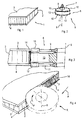
Figure 1 is a perspective and fragmentary view of a composite panel; -
Figure 2 is a very schematic perspective view of a tool for arranging an edge of composite panel on the application of a finishing strip; -
Figure 3 is a longitudinal section taken along the axis of symmetry of the tool inFigure 2 and of a panel during machining; -
Figure 4 is a very schematic and interrupted view that shows the interaction between a panel to be edge-banded and a tool like the one inFigure 2 ; -
Figure 5 is a top view inFigure 4 ; -
Figure 6 is a schematic and fragmentary top view of a panel and of an edge-banding unit during the application of a finishing strip; -
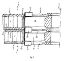
Figure 7 is a section like that inFigure 3 , but in an embodiment of the tool and of the panel. - As shown in
Figure 1 , acomposite panel 1 comprises a compressibleinternal part 2, for example made of cardboard, with a honeycomb structure, enclosed between afirst laminar element 3 and asecond laminar element 4 that form the visible faces of thepanel 1. - With reference to
Figures 2 , atool 5 comprises atool body 6 and ashank 7 that is used for coupling a spindle, or electric spindle, with a machine tool that is not shown that rotates thetool body 6 around anaxis 8. - As shown in
Figure 3 , thetool body 6 comprises afirst tool part 9, peripherally provided with a first cuttingperipheral crown 10 that has a height, measured along theaxis 8, that is at least equal to or hardly greater than the thickness of thefirst laminar element 3. Thetool body 6 further comprises asecond tool part 11, peripherally provided with a secondperipheral cutting crown 12 that has a height, measured along theaxis 8, that is the same as or hardly greater than, the thickness of thesecond laminar element 4. Thefirst tool part 9 and thesecond tool part 11 can be formed of disc-type milling cutters of conventional type, splined on a central hub that is not shown. Between thefirst tool part 9 and thesecond tool part 11 there is interposed apressing element 13, having a diameter substantially corresponding to the diameter of thefirst tool part 9 and of thesecond tool part 11 and arranged for compressing a more outerperipheral portion 14 of theinner part 2 of thepanel 1. - Alternatively, the
pressing element 13 can have a lesser or greater diameter than the diameter of thefirst tool part 9 and of thesecond tool part 11. - The
pressing element 13 can be symmetrical to theaxis 8, for example thepressing element 13 can have a cylindrical shape, with an axis substantially coinciding with theaxis 8, or a barrel shape. - Also the
pressing element 13 can be splined like the first and thesecond tool part - In an alternative embodiment the
pressing element 13 can be splined on the hub by revolving means, in particular by bearing means. - In this case the
pressing element 13 can be induced to roll around theaxis 8 at a speed different from the rotation speed of thefirst tool part 9 and of thesecond tool part 11. In particular thepressing element 13, by interacting with theperipheral portion 14, can be made to rotate at a speed that is substantially the same as the advancing speed of thetool 5 along the advance direction A. - Alternatively, the
pressing element 13 can be rotated by rotating means that is not shown, at any speed. - In a further embodiment the
pressing element 13 might not rotate around theaxis 8. - As shown in
Figure 4 , in which the operating zone of thetool 5 is shown by a dot-and-dash line, theperipheral portion 14 is formed by bending the laminae of the honeycomb structure in a direction opposite the advance direction A of thetool 5, which is rotated around theaxis 8 in a direction indicated by the arrow F. - As shown in
Figure 5 , the compressedperipheral portion 14 may be more or less extended: in particular, if thetool 5 is advanced in the direction A at a greater cutting depth P, theperipheral portion 14 occupies a more extended depth P1, whilst if thetool 5 is advanced in the direction A at a lesser cutting depth P, theperipheral portion 14 occupies a less extended depth P1. - As shown in
Figure 6 , apanel 1 that has aperipheral portion 14 compressed for a certain depth P1 can be directly edge-banded by an edge-banding unit 18 of conventional type, for example comprising a supportingplate 19, an applyingroller 20 that presses afinishing strip 21 against the free face of the compressedperipheral portion 14 that provides a sufficiently stable support. Upstream of the applyingroller 20 there is provided a distributingroller 22 that is arranged for distributing a suitable layer of glue on the compressedperipheral portion 14 before thefinishing strip 21 is pressed against theperipheral portion 14 whilst thepanel 1 is moved along a work direction B. - With reference to
Figure 7 , there is shown a tool embodiment that is particularly suitable when twopanels 1 have to be machined that are superimposed and glued one to the other by a fixing layer 23. Thefirst tool part 9 is arranged facing thefirst laminar element 3 of one of thepanels 1 and thesecond tool part 11 is arranged facing thesecond laminar element 4 of theother panel 1. Between thefirst tool part 9 and thesecond tool part 11 there is interposed a further tool part 24 that is peripherally provided with afirst cutting part 25 that is arranged at the fixing layer 23 to cut at least thesecond laminar element 4 of a panel and thefirst laminar element 3 of theother panel 1. Between thefirst tool part 9 and the further tool part 24 there is interposed a firstpressing element 26 and between the further tool part 24 and thesecond tool part 11 there is interposed a secondpressing element 27. - The first
pressing element 26 and the secondpressing element 27 are structurally similar to thepressing element 13 and have the same function as the latter.
Claims (19)
- Apparatus, comprising a tool body (6) that is suitable for being mounted on a machine for machining panels for rotating around an own axis (8), cutting elements (10, 12; 10, 12, 25) arranged on the periphery of said body (6) for removing parts (3, 4; 3, 4, 23, 3, 4) of a panel (1) to be cut, characterised in that said cutting elements (10, 12; 10, 12, 25) are arranged in peripheral crowns spaced apart from one another along said axis (8) for removing parts of laminar elements (3, 4; 3, 4, 23, 3, 4) of a panel (1) to be machined and that between at least two consecutive crowns along said axis (8) there is interposed a non-cutting pressing element (13; 26, 27) for compressing a peripheral part (14) of an internal honeycomb structure (2) of said panel (1).
- Apparatus according to claim 1, wherein said cutting elements (10, 12; 10, 12, 25) are part of disc-type milling cutters.
- Apparatus according to claim 1, or 2, wherein said cutting elements (10, 12) of each crown belong respectively to a first axial tool portion (9) and to a second axial tool portion (11).
- Apparatus according to claim 3, wherein between said first axial tool portion (9) and said second axial tool portion (11) there is interposed, along said axis (8), a single pressing element (13).
- Apparatus according to claim 4, wherein said single pressing element (13) is substantially symmetrical to said axis (8).
- Apparatus according to claim 4, or 5, wherein said single pressing element (13) has a substantially cylindrical shape.
- Apparatus according to any one of claims 4 to 6, and further comprising revolving means, said revolving means being interposed between said pressing element (13) and said body (6).
- Apparatus according to claim 3, wherein between said first axial tool portion (9) and said second axial tool portion (11) there is interposed along said axis (8) a further axial tool portion (24).
- Apparatus according to claim 8, wherein between said first axial tool portion (9) and said further axial tool portion (24) along said axis (8) there is interposed a first pressing element (26).
- Apparatus according to claims 8, or 9, wherein between said further axial tool portion (24) and said second axial tool portion (11) along said axis (8) there is interposed a second pressing element (27).
- Apparatus according to claim 9, or 10, wherein said first pressing element (26) and/or said second pressing element (27) are substantially symmetrical to said axis (8).
- Apparatus according to any one of claims 9 to 11, wherein said first pressing element (26) and/or said second pressing element (27) have a substantially cylindrical shape.
- Apparatus according to any one of claims 9 to 12, wherein said first pressing element (26) and/or said second pressing element (27) have substantially the same external diameter.
- Apparatus according to any one of claims 9 to 13, and further comprising further revolving means, said further revolving means being interposed between said first pressing element (26) and/or said second pressing element (27) and said body (6).
- Method for edge-banding a panel (1) having an inner portion (2) with a compressible structure comprised between two laminar elements (3, 4) that define the widest faces thereof, comprising removing peripheral portions of each laminar element (3, 4; 3, 4, 23) for a certain depth (P) and compressing the inner portion (2) substantially of said depth so as to define a compressed part(14) that is suitable for acting as a support for a finishing strip (21).
- Method according to claim 15, wherein said removing further comprises removing an interface zone (23) along which two superimposed panels (1) are joined together.
- Method according to claim 16, wherein said compressing comprises compressing each said inner portion (2) of the respective said two panels (1).
- Panel (1) made of composite material, comprising an inner portion (2) with a compressible structure comprised between two laminar elements (3, 4) that define the widest faces thereof and a finishing strip (21) applied to the periphery of said panel (1), characterised in that said finishing strip (21) is applied to a compressed peripheral part (14) of said inner portion (2).
- Panel made of composite material, comprising at least two superimposed panels (1), each having an inner portion (2) with a compressible structure comprised between two laminar elements (3, 4) that define the widest faces thereof and a finishing strip (21) applied to the periphery of said panel (1), characterised in that said finishing strip (21) is common to said at least two panels (1) and is applied to compressed peripheral parts (14) of each said inner portion (2).
Priority Applications (1)
| Application Number | Priority Date | Filing Date | Title |
|---|---|---|---|
| PL08156526T PL1997597T3 (en) | 2007-05-21 | 2008-05-20 | Apparatus and method for edge-banding panels and edge-banded composite panel |
Applications Claiming Priority (1)
| Application Number | Priority Date | Filing Date | Title |
|---|---|---|---|
| IT000168A ITMO20070168A1 (en) | 2007-05-21 | 2007-05-21 | APPARATUS AND METHOD TO BORDER PANELS AND EDGED COMPOSITE PANEL |
Publications (3)
| Publication Number | Publication Date |
|---|---|
| EP1997597A2 true EP1997597A2 (en) | 2008-12-03 |
| EP1997597A3 EP1997597A3 (en) | 2013-05-08 |
| EP1997597B1 EP1997597B1 (en) | 2019-04-03 |
Family
ID=39701102
Family Applications (1)
| Application Number | Title | Priority Date | Filing Date |
|---|---|---|---|
| EP08156526.9A Active EP1997597B1 (en) | 2007-05-21 | 2008-05-20 | Apparatus and method for edge-banding panels and edge-banded composite panel |
Country Status (3)
| Country | Link |
|---|---|
| EP (1) | EP1997597B1 (en) |
| IT (1) | ITMO20070168A1 (en) |
| PL (1) | PL1997597T3 (en) |
Cited By (6)
| Publication number | Priority date | Publication date | Assignee | Title |
|---|---|---|---|---|
| ITUB20153838A1 (en) * | 2015-09-23 | 2017-03-23 | Samec S P A | METHOD FOR APPLYING A BORDER ELEMENT ON A PANEL |
| CN108098962A (en) * | 2017-12-13 | 2018-06-01 | 广州荷力胜蜂窝材料股份有限公司 | A kind of cellular board welter |
| EP3875175A1 (en) | 2020-03-04 | 2021-09-08 | Luigino Salvador | Glue distributor assembly for edgebanding machine and method of panel edgebanding |
| CN115302589A (en) * | 2022-07-08 | 2022-11-08 | 哈尔滨职业技术学院 | Raw material cutting device for manufacturing plate-type furniture and using method |
| WO2023023681A1 (en) | 2021-08-24 | 2023-03-02 | Brodnik Gerhard | Individualization of items of self-build furniture |
| EP4241948A1 (en) * | 2022-03-07 | 2023-09-13 | Bodo Mündkemüller | Aggregate for machining an edge surface of a wood-based panel and method for machining the same |
Family Cites Families (7)
| Publication number | Priority date | Publication date | Assignee | Title |
|---|---|---|---|---|
| CA761402A (en) * | 1951-01-28 | 1967-06-20 | E. Munk Edmund | Method of and press mould for covering edges and profiles |
| US2833003A (en) * | 1954-11-22 | 1958-05-06 | Joseph B Bourne | Structural panel |
| DE1033499B (en) * | 1955-10-01 | 1958-07-03 | Hexcel Products Inc | Railway building material with honeycomb cells and process for its manufacture |
| DE1914403A1 (en) * | 1969-03-21 | 1970-10-08 | Heinrich Brandt Maschb | Milling device for removing the protruding lengthways of the strip material applied to the face of plate-shaped workpieces |
| US5312504A (en) * | 1992-12-11 | 1994-05-17 | Jorde Edward P | Edge veneering |
| US5433563A (en) * | 1994-08-25 | 1995-07-18 | Fred M. Velepec Co., Inc. | Cutting tool |
| DE502007001395D1 (en) * | 2007-02-26 | 2009-10-08 | Homag Holzbearbeitungssysteme | Method for adhering edge material to lightweight panels |
-
2007
- 2007-05-21 IT IT000168A patent/ITMO20070168A1/en unknown
-
2008
- 2008-05-20 PL PL08156526T patent/PL1997597T3/en unknown
- 2008-05-20 EP EP08156526.9A patent/EP1997597B1/en active Active
Cited By (8)
| Publication number | Priority date | Publication date | Assignee | Title |
|---|---|---|---|---|
| ITUB20153838A1 (en) * | 2015-09-23 | 2017-03-23 | Samec S P A | METHOD FOR APPLYING A BORDER ELEMENT ON A PANEL |
| EP3147091A1 (en) | 2015-09-23 | 2017-03-29 | Samec S.p.A. | Method for applying an edge-banding element to a lightweight panel |
| CN108098962A (en) * | 2017-12-13 | 2018-06-01 | 广州荷力胜蜂窝材料股份有限公司 | A kind of cellular board welter |
| EP3875175A1 (en) | 2020-03-04 | 2021-09-08 | Luigino Salvador | Glue distributor assembly for edgebanding machine and method of panel edgebanding |
| EP3875176A2 (en) | 2020-03-04 | 2021-09-08 | Luigino Salvador | Glue distributor assembly for edgebanding machine and method of panel edgebanding |
| WO2023023681A1 (en) | 2021-08-24 | 2023-03-02 | Brodnik Gerhard | Individualization of items of self-build furniture |
| EP4241948A1 (en) * | 2022-03-07 | 2023-09-13 | Bodo Mündkemüller | Aggregate for machining an edge surface of a wood-based panel and method for machining the same |
| CN115302589A (en) * | 2022-07-08 | 2022-11-08 | 哈尔滨职业技术学院 | Raw material cutting device for manufacturing plate-type furniture and using method |
Also Published As
| Publication number | Publication date |
|---|---|
| EP1997597A3 (en) | 2013-05-08 |
| ITMO20070168A1 (en) | 2008-11-22 |
| PL1997597T3 (en) | 2019-09-30 |
| EP1997597B1 (en) | 2019-04-03 |
Similar Documents
| Publication | Publication Date | Title |
|---|---|---|
| EP1997597B1 (en) | Apparatus and method for edge-banding panels and edge-banded composite panel | |
| CN101862972B (en) | Rotational resistance applying device in main shaft driving device for machine tool | |
| DK3105009T3 (en) | Mobile woodworking machine for machining the edge area of a wooden furniture top | |
| BR9508575A (en) | Apparatus for forming layers of a material having a uniform thickness and for cutting individual portions thereof | |
| CA2455195A1 (en) | Rotary cutter and method for manufacturing fibrous product using the same | |
| CA2260081A1 (en) | Synthetic foam surface contouring machine | |
| EP0848996B1 (en) | Cutting cylinder for a document shredding machine and method of making same | |
| KR101419493B1 (en) | Rotary tissue cutting device | |
| PT2567043E (en) | Method for producing panels with bevelled edges | |
| CN111283816B (en) | Satellite type circular knife die-cutting machine | |
| JP5561727B2 (en) | Grooving blade and slotter equipped with the grooved blade | |
| US10493652B2 (en) | Veneer peeling apparatus | |
| US3474706A (en) | Process for making a textured surface panel | |
| US5411066A (en) | Method of producing veneer | |
| JP4712260B2 (en) | Rotating device with adjustable force for processing webs | |
| EP4260955B1 (en) | Device for finishing at least one plate-shaped workpiece | |
| EP1488128B1 (en) | Friction lining carrier, especially brake shoe, for parking or drum brakes and corresponding method of production and device for carrying out said method | |
| FI121808B (en) | Fasfräs | |
| US7299670B2 (en) | Method and apparatus for producing cylindrical components having bent portions | |
| JPH0511965Y2 (en) | ||
| ITMI20010756A1 (en) | DEVICE FOR THE PROCESSING OF BOOKS BLOCKS OR BOOKLETS FOR THE APPLICATION OF GLUES WITH A TOOL HEAD | |
| AT524999B1 (en) | Method of manufacturing a friction disk assembly | |
| EP1082195A1 (en) | Vibration damping sheet for cutting disks | |
| JPH047885B2 (en) | ||
| DK2251164T3 (en) | Cutting tool |
Legal Events
| Date | Code | Title | Description |
|---|---|---|---|
| PUAI | Public reference made under article 153(3) epc to a published international application that has entered the european phase |
Free format text: ORIGINAL CODE: 0009012 |
|
| AK | Designated contracting states |
Kind code of ref document: A2 Designated state(s): AT BE BG CH CY CZ DE DK EE ES FI FR GB GR HR HU IE IS IT LI LT LU LV MC MT NL NO PL PT RO SE SI SK TR |
|
| AX | Request for extension of the european patent |
Extension state: AL BA MK RS |
|
| PUAL | Search report despatched |
Free format text: ORIGINAL CODE: 0009013 |
|
| AK | Designated contracting states |
Kind code of ref document: A3 Designated state(s): AT BE BG CH CY CZ DE DK EE ES FI FR GB GR HR HU IE IS IT LI LT LU LV MC MT NL NO PL PT RO SE SI SK TR |
|
| AX | Request for extension of the european patent |
Extension state: AL BA MK RS |
|
| RIC1 | Information provided on ipc code assigned before grant |
Ipc: B29C 63/00 20060101ALI20130404BHEP Ipc: B27D 5/00 20060101AFI20130404BHEP Ipc: E04C 2/36 20060101ALI20130404BHEP Ipc: B32B 3/02 20060101ALI20130404BHEP |
|
| 17P | Request for examination filed |
Effective date: 20131108 |
|
| RBV | Designated contracting states (corrected) |
Designated state(s): AT BE BG CH CY CZ DE DK EE ES FI FR GB GR HR HU IE IS IT LI LT LU LV MC MT NL NO PL PT RO SE SI SK TR |
|
| AKX | Designation fees paid |
Designated state(s): AT BE BG CH CY CZ DE DK EE ES FI FR GB GR HR HU IE IS IT LI LT LU LV MC MT NL NO PL PT RO SE SI SK TR |
|
| 17Q | First examination report despatched |
Effective date: 20150106 |
|
| STAA | Information on the status of an ep patent application or granted ep patent |
Free format text: STATUS: EXAMINATION IS IN PROGRESS |
|
| REG | Reference to a national code |
Ref country code: DE Ref legal event code: R079 Ref document number: 602008059572 Country of ref document: DE Free format text: PREVIOUS MAIN CLASS: B27D0005000000 Ipc: B27D0001060000 |
|
| GRAP | Despatch of communication of intention to grant a patent |
Free format text: ORIGINAL CODE: EPIDOSNIGR1 |
|
| STAA | Information on the status of an ep patent application or granted ep patent |
Free format text: STATUS: GRANT OF PATENT IS INTENDED |
|
| RIC1 | Information provided on ipc code assigned before grant |
Ipc: A47B 96/20 20060101ALI20180928BHEP Ipc: B27D 1/06 20060101AFI20180928BHEP |
|
| INTG | Intention to grant announced |
Effective date: 20181019 |
|
| GRAS | Grant fee paid |
Free format text: ORIGINAL CODE: EPIDOSNIGR3 |
|
| GRAA | (expected) grant |
Free format text: ORIGINAL CODE: 0009210 |
|
| STAA | Information on the status of an ep patent application or granted ep patent |
Free format text: STATUS: THE PATENT HAS BEEN GRANTED |
|
| AK | Designated contracting states |
Kind code of ref document: B1 Designated state(s): AT BE BG CH CY CZ DE DK EE ES FI FR GB GR HR HU IE IS IT LI LT LU LV MC MT NL NO PL PT RO SE SI SK TR |
|
| REG | Reference to a national code |
Ref country code: GB Ref legal event code: FG4D |
|
| REG | Reference to a national code |
Ref country code: CH Ref legal event code: EP Ref country code: AT Ref legal event code: REF Ref document number: 1115156 Country of ref document: AT Kind code of ref document: T Effective date: 20190415 |
|
| REG | Reference to a national code |
Ref country code: DE Ref legal event code: R096 Ref document number: 602008059572 Country of ref document: DE |
|
| REG | Reference to a national code |
Ref country code: IE Ref legal event code: FG4D |
|
| REG | Reference to a national code |
Ref country code: NL Ref legal event code: MP Effective date: 20190403 |
|
| REG | Reference to a national code |
Ref country code: LT Ref legal event code: MG4D |
|
| PG25 | Lapsed in a contracting state [announced via postgrant information from national office to epo] |
Ref country code: NL Free format text: LAPSE BECAUSE OF FAILURE TO SUBMIT A TRANSLATION OF THE DESCRIPTION OR TO PAY THE FEE WITHIN THE PRESCRIBED TIME-LIMIT Effective date: 20190403 |
|
| PG25 | Lapsed in a contracting state [announced via postgrant information from national office to epo] |
Ref country code: ES Free format text: LAPSE BECAUSE OF FAILURE TO SUBMIT A TRANSLATION OF THE DESCRIPTION OR TO PAY THE FEE WITHIN THE PRESCRIBED TIME-LIMIT Effective date: 20190403 Ref country code: CZ Free format text: LAPSE BECAUSE OF FAILURE TO SUBMIT A TRANSLATION OF THE DESCRIPTION OR TO PAY THE FEE WITHIN THE PRESCRIBED TIME-LIMIT Effective date: 20190403 Ref country code: LT Free format text: LAPSE BECAUSE OF FAILURE TO SUBMIT A TRANSLATION OF THE DESCRIPTION OR TO PAY THE FEE WITHIN THE PRESCRIBED TIME-LIMIT Effective date: 20190403 Ref country code: HR Free format text: LAPSE BECAUSE OF FAILURE TO SUBMIT A TRANSLATION OF THE DESCRIPTION OR TO PAY THE FEE WITHIN THE PRESCRIBED TIME-LIMIT Effective date: 20190403 Ref country code: FI Free format text: LAPSE BECAUSE OF FAILURE TO SUBMIT A TRANSLATION OF THE DESCRIPTION OR TO PAY THE FEE WITHIN THE PRESCRIBED TIME-LIMIT Effective date: 20190403 Ref country code: PT Free format text: LAPSE BECAUSE OF FAILURE TO SUBMIT A TRANSLATION OF THE DESCRIPTION OR TO PAY THE FEE WITHIN THE PRESCRIBED TIME-LIMIT Effective date: 20190803 Ref country code: NO Free format text: LAPSE BECAUSE OF FAILURE TO SUBMIT A TRANSLATION OF THE DESCRIPTION OR TO PAY THE FEE WITHIN THE PRESCRIBED TIME-LIMIT Effective date: 20190703 Ref country code: SE Free format text: LAPSE BECAUSE OF FAILURE TO SUBMIT A TRANSLATION OF THE DESCRIPTION OR TO PAY THE FEE WITHIN THE PRESCRIBED TIME-LIMIT Effective date: 20190403 |
|
| PG25 | Lapsed in a contracting state [announced via postgrant information from national office to epo] |
Ref country code: LV Free format text: LAPSE BECAUSE OF FAILURE TO SUBMIT A TRANSLATION OF THE DESCRIPTION OR TO PAY THE FEE WITHIN THE PRESCRIBED TIME-LIMIT Effective date: 20190403 Ref country code: GR Free format text: LAPSE BECAUSE OF FAILURE TO SUBMIT A TRANSLATION OF THE DESCRIPTION OR TO PAY THE FEE WITHIN THE PRESCRIBED TIME-LIMIT Effective date: 20190704 Ref country code: BG Free format text: LAPSE BECAUSE OF FAILURE TO SUBMIT A TRANSLATION OF THE DESCRIPTION OR TO PAY THE FEE WITHIN THE PRESCRIBED TIME-LIMIT Effective date: 20190703 |
|
| REG | Reference to a national code |
Ref country code: CH Ref legal event code: PL |
|
| PG25 | Lapsed in a contracting state [announced via postgrant information from national office to epo] |
Ref country code: IS Free format text: LAPSE BECAUSE OF FAILURE TO SUBMIT A TRANSLATION OF THE DESCRIPTION OR TO PAY THE FEE WITHIN THE PRESCRIBED TIME-LIMIT Effective date: 20190803 |
|
| REG | Reference to a national code |
Ref country code: DE Ref legal event code: R097 Ref document number: 602008059572 Country of ref document: DE |
|
| PG25 | Lapsed in a contracting state [announced via postgrant information from national office to epo] |
Ref country code: MC Free format text: LAPSE BECAUSE OF FAILURE TO SUBMIT A TRANSLATION OF THE DESCRIPTION OR TO PAY THE FEE WITHIN THE PRESCRIBED TIME-LIMIT Effective date: 20190403 Ref country code: RO Free format text: LAPSE BECAUSE OF FAILURE TO SUBMIT A TRANSLATION OF THE DESCRIPTION OR TO PAY THE FEE WITHIN THE PRESCRIBED TIME-LIMIT Effective date: 20190403 Ref country code: LI Free format text: LAPSE BECAUSE OF NON-PAYMENT OF DUE FEES Effective date: 20190531 Ref country code: CH Free format text: LAPSE BECAUSE OF NON-PAYMENT OF DUE FEES Effective date: 20190531 Ref country code: EE Free format text: LAPSE BECAUSE OF FAILURE TO SUBMIT A TRANSLATION OF THE DESCRIPTION OR TO PAY THE FEE WITHIN THE PRESCRIBED TIME-LIMIT Effective date: 20190403 Ref country code: SK Free format text: LAPSE BECAUSE OF FAILURE TO SUBMIT A TRANSLATION OF THE DESCRIPTION OR TO PAY THE FEE WITHIN THE PRESCRIBED TIME-LIMIT Effective date: 20190403 Ref country code: DK Free format text: LAPSE BECAUSE OF FAILURE TO SUBMIT A TRANSLATION OF THE DESCRIPTION OR TO PAY THE FEE WITHIN THE PRESCRIBED TIME-LIMIT Effective date: 20190403 |
|
| REG | Reference to a national code |
Ref country code: BE Ref legal event code: MM Effective date: 20190531 |
|
| PLBE | No opposition filed within time limit |
Free format text: ORIGINAL CODE: 0009261 |
|
| STAA | Information on the status of an ep patent application or granted ep patent |
Free format text: STATUS: NO OPPOSITION FILED WITHIN TIME LIMIT |
|
| PG25 | Lapsed in a contracting state [announced via postgrant information from national office to epo] |
Ref country code: LU Free format text: LAPSE BECAUSE OF NON-PAYMENT OF DUE FEES Effective date: 20190520 |
|
| 26N | No opposition filed |
Effective date: 20200106 |
|
| GBPC | Gb: european patent ceased through non-payment of renewal fee |
Effective date: 20190703 |
|
| PG25 | Lapsed in a contracting state [announced via postgrant information from national office to epo] |
Ref country code: TR Free format text: LAPSE BECAUSE OF FAILURE TO SUBMIT A TRANSLATION OF THE DESCRIPTION OR TO PAY THE FEE WITHIN THE PRESCRIBED TIME-LIMIT Effective date: 20190403 |
|
| PG25 | Lapsed in a contracting state [announced via postgrant information from national office to epo] |
Ref country code: GB Free format text: LAPSE BECAUSE OF NON-PAYMENT OF DUE FEES Effective date: 20190703 Ref country code: IE Free format text: LAPSE BECAUSE OF NON-PAYMENT OF DUE FEES Effective date: 20190520 |
|
| REG | Reference to a national code |
Ref country code: AT Ref legal event code: UEP Ref document number: 1115156 Country of ref document: AT Kind code of ref document: T Effective date: 20190403 |
|
| PG25 | Lapsed in a contracting state [announced via postgrant information from national office to epo] |
Ref country code: BE Free format text: LAPSE BECAUSE OF NON-PAYMENT OF DUE FEES Effective date: 20190531 Ref country code: SI Free format text: LAPSE BECAUSE OF FAILURE TO SUBMIT A TRANSLATION OF THE DESCRIPTION OR TO PAY THE FEE WITHIN THE PRESCRIBED TIME-LIMIT Effective date: 20190403 |
|
| PG25 | Lapsed in a contracting state [announced via postgrant information from national office to epo] |
Ref country code: FR Free format text: LAPSE BECAUSE OF NON-PAYMENT OF DUE FEES Effective date: 20190603 |
|
| PG25 | Lapsed in a contracting state [announced via postgrant information from national office to epo] |
Ref country code: CY Free format text: LAPSE BECAUSE OF FAILURE TO SUBMIT A TRANSLATION OF THE DESCRIPTION OR TO PAY THE FEE WITHIN THE PRESCRIBED TIME-LIMIT Effective date: 20190403 |
|
| PG25 | Lapsed in a contracting state [announced via postgrant information from national office to epo] |
Ref country code: HU Free format text: LAPSE BECAUSE OF FAILURE TO SUBMIT A TRANSLATION OF THE DESCRIPTION OR TO PAY THE FEE WITHIN THE PRESCRIBED TIME-LIMIT; INVALID AB INITIO Effective date: 20080520 Ref country code: MT Free format text: LAPSE BECAUSE OF FAILURE TO SUBMIT A TRANSLATION OF THE DESCRIPTION OR TO PAY THE FEE WITHIN THE PRESCRIBED TIME-LIMIT Effective date: 20190403 |
|
| PGFP | Annual fee paid to national office [announced via postgrant information from national office to epo] |
Ref country code: PL Payment date: 20210507 Year of fee payment: 14 Ref country code: AT Payment date: 20210518 Year of fee payment: 14 |
|
| REG | Reference to a national code |
Ref country code: AT Ref legal event code: MM01 Ref document number: 1115156 Country of ref document: AT Kind code of ref document: T Effective date: 20220520 |
|
| PG25 | Lapsed in a contracting state [announced via postgrant information from national office to epo] |
Ref country code: AT Free format text: LAPSE BECAUSE OF NON-PAYMENT OF DUE FEES Effective date: 20220520 |
|
| P01 | Opt-out of the competence of the unified patent court (upc) registered |
Effective date: 20230518 |
|
| PG25 | Lapsed in a contracting state [announced via postgrant information from national office to epo] |
Ref country code: PL Free format text: LAPSE BECAUSE OF NON-PAYMENT OF DUE FEES Effective date: 20220520 |
|
| PGFP | Annual fee paid to national office [announced via postgrant information from national office to epo] |
Ref country code: DE Payment date: 20250519 Year of fee payment: 18 |
|
| PGFP | Annual fee paid to national office [announced via postgrant information from national office to epo] |
Ref country code: IT Payment date: 20260206 Year of fee payment: 19 |