EP3875020A1 - Endoscope with an optical waveguide device, method for manufacturing an endoscope with an optical waveguide device and use of a method for manufacturing an endoscope - Google Patents
Endoscope with an optical waveguide device, method for manufacturing an endoscope with an optical waveguide device and use of a method for manufacturing an endoscope Download PDFInfo
- Publication number
- EP3875020A1 EP3875020A1 EP21158031.1A EP21158031A EP3875020A1 EP 3875020 A1 EP3875020 A1 EP 3875020A1 EP 21158031 A EP21158031 A EP 21158031A EP 3875020 A1 EP3875020 A1 EP 3875020A1
- Authority
- EP
- European Patent Office
- Prior art keywords
- inner shaft
- shaft
- endoscope
- light guide
- guide segment
- Prior art date
- Legal status (The legal status is an assumption and is not a legal conclusion. Google has not performed a legal analysis and makes no representation as to the accuracy of the status listed.)
- Pending
Links
Images

Classifications
-
- G—PHYSICS
- G02—OPTICS
- G02B—OPTICAL ELEMENTS, SYSTEMS OR APPARATUS
- G02B23/00—Telescopes, e.g. binoculars; Periscopes; Instruments for viewing the inside of hollow bodies; Viewfinders; Optical aiming or sighting devices
- G02B23/24—Instruments or systems for viewing the inside of hollow bodies, e.g. fibrescopes
- G02B23/2407—Optical details
- G02B23/2461—Illumination
- G02B23/2469—Illumination using optical fibres
-
- A—HUMAN NECESSITIES
- A61—MEDICAL OR VETERINARY SCIENCE; HYGIENE
- A61B—DIAGNOSIS; SURGERY; IDENTIFICATION
- A61B1/00—Instruments for performing medical examinations of the interior of cavities or tubes of the body by visual or photographical inspection, e.g. endoscopes; Illuminating arrangements therefor
- A61B1/00064—Constructional details of the endoscope body
- A61B1/0011—Manufacturing of endoscope parts
-
- A—HUMAN NECESSITIES
- A61—MEDICAL OR VETERINARY SCIENCE; HYGIENE
- A61B—DIAGNOSIS; SURGERY; IDENTIFICATION
- A61B1/00—Instruments for performing medical examinations of the interior of cavities or tubes of the body by visual or photographical inspection, e.g. endoscopes; Illuminating arrangements therefor
- A61B1/00163—Optical arrangements
- A61B1/00165—Optical arrangements with light-conductive means, e.g. fibre optics
- A61B1/00167—Details of optical fibre bundles, e.g. shape or fibre distribution
-
- A—HUMAN NECESSITIES
- A61—MEDICAL OR VETERINARY SCIENCE; HYGIENE
- A61B—DIAGNOSIS; SURGERY; IDENTIFICATION
- A61B1/00—Instruments for performing medical examinations of the interior of cavities or tubes of the body by visual or photographical inspection, e.g. endoscopes; Illuminating arrangements therefor
- A61B1/06—Instruments for performing medical examinations of the interior of cavities or tubes of the body by visual or photographical inspection, e.g. endoscopes; Illuminating arrangements therefor with illuminating arrangements
- A61B1/07—Instruments for performing medical examinations of the interior of cavities or tubes of the body by visual or photographical inspection, e.g. endoscopes; Illuminating arrangements therefor with illuminating arrangements using light-conductive means, e.g. optical fibres
-
- G—PHYSICS
- G02—OPTICS
- G02B—OPTICAL ELEMENTS, SYSTEMS OR APPARATUS
- G02B6/00—Light guides; Structural details of arrangements comprising light guides and other optical elements, e.g. couplings
- G02B6/04—Light guides; Structural details of arrangements comprising light guides and other optical elements, e.g. couplings formed by bundles of fibres
- G02B6/06—Light guides; Structural details of arrangements comprising light guides and other optical elements, e.g. couplings formed by bundles of fibres the relative position of the fibres being the same at both ends, e.g. for transporting images
-
- G—PHYSICS
- G02—OPTICS
- G02B—OPTICAL ELEMENTS, SYSTEMS OR APPARATUS
- G02B6/00—Light guides; Structural details of arrangements comprising light guides and other optical elements, e.g. couplings
- G02B6/46—Processes or apparatus adapted for installing or repairing optical fibres or optical cables
- G02B6/50—Underground or underwater installation; Installation through tubing, conduits or ducts
-
- A—HUMAN NECESSITIES
- A61—MEDICAL OR VETERINARY SCIENCE; HYGIENE
- A61B—DIAGNOSIS; SURGERY; IDENTIFICATION
- A61B1/00—Instruments for performing medical examinations of the interior of cavities or tubes of the body by visual or photographical inspection, e.g. endoscopes; Illuminating arrangements therefor
- A61B1/002—Instruments for performing medical examinations of the interior of cavities or tubes of the body by visual or photographical inspection, e.g. endoscopes; Illuminating arrangements therefor having rod-lens arrangements
-
- B—PERFORMING OPERATIONS; TRANSPORTING
- B23—MACHINE TOOLS; METAL-WORKING NOT OTHERWISE PROVIDED FOR
- B23K—SOLDERING OR UNSOLDERING; WELDING; CLADDING OR PLATING BY SOLDERING OR WELDING; CUTTING BY APPLYING HEAT LOCALLY, e.g. FLAME CUTTING; WORKING BY LASER BEAM
- B23K2103/00—Materials to be soldered, welded or cut
- B23K2103/08—Non-ferrous metals or alloys
-
- B—PERFORMING OPERATIONS; TRANSPORTING
- B23—MACHINE TOOLS; METAL-WORKING NOT OTHERWISE PROVIDED FOR
- B23K—SOLDERING OR UNSOLDERING; WELDING; CLADDING OR PLATING BY SOLDERING OR WELDING; CUTTING BY APPLYING HEAT LOCALLY, e.g. FLAME CUTTING; WORKING BY LASER BEAM
- B23K26/00—Working by laser beam, e.g. welding, cutting or boring
- B23K26/34—Laser welding for purposes other than joining
- B23K26/342—Build-up welding
Definitions
- the present invention relates to a method for manufacturing an endoscope with a light guide device according to the preamble of claim 1. Furthermore, the present invention relates to a use of a method for manufacturing an endoscope according to the preamble of claim 5. The present invention also relates to an endoscope with a light guide device according to the preamble of claim 6.
- Light source devices which are separate or integrated into the proximal end of the endoscope are often used to generate illuminating light with a high luminous flux.
- the illuminating light is transmitted from the proximal end to the distal end of the endoscope by means of one or more bundles of light guide elements of a light guide device.
- guide segments or segments in general are already known from the prior art that on the Outer surface of the inner shaft are arranged in the distal end portion of the inner shaft and determine the alignment of the inner shaft relative to the outer shaft by their shape in the radial direction or in the circumferential direction, in particular by a variable height or thickness in the radial direction, the extent or angular extent of the segment or guide segment in the circumferential direction, the position or arrangement of the light guide elements in the distal end portion of the endoscope is determined and the shape of the segment or guide segment in the axial direction, in particular at the circumferential, radially extending edges, the alignment of the light guide elements.
- the arrangement and alignment of the light guide elements in the distal end section of the endoscope can be determined via the shape of the segment or guide segment, so that, for example, a desired alignment, preferably angled to the axial extension of the inner and / or outer shaft, can be determined a simultaneously bundled or concentrated arrangement of the light guide elements can be achieved in a uniform manner.
- a multi-stage process or a multi-stage method is generally provided for generating and / or arranging the segment or guide segment on the inner shaft.
- a blank or base body / green body of the segment or guide segment is soldered onto the distal end section of the inner shaft.
- This preliminary stage of the final guide segment with regard to the outer shape generally still has a uniform height, thickness or radial extension.
- the assembly is comprised of the inner shaft and the preliminary stage of the guide segment is then machined in a machining step, preferably by over-turning, so that the desired shape of the guide segment, in particular the desired thickness or height of the guide segment that is variable in the circumferential direction, is achieved.
- a general disadvantage of this type of production or provision of the assembly consisting of the inner shaft and the guide segment is, on the one hand, the relatively high number of processing steps.
- brass is also often used as the material of the guide element, since it can be easily processed during soldering and over-turning.
- the inherently low biocompatibility and / or the classification of brass as an allergen can only be tolerated, however, since the potentially triggerable biochemical reactions are small due to the small area or surface of the guide elements.
- Another disadvantage is the previously known procedure for fastening the blank of the guide segment or for connecting the inner shaft to the blank of the guide segment.
- soldering using a solder as the connecting material problems with adhesion can arise in particular in a subsequent or subsequent mechanical, preferably cutting, machining process, which in the worst case leads to the soldered-on guide segment or its preliminary stage being detached from the inner shaft or flake off.
- the present invention is therefore based on the object of overcoming the aforementioned disadvantages in the prior art and in particular to propose an endoscope and a method for producing an endoscope, as well as a use of the method, which provide a fast, safe and reliable arrangement of a known guide segment allow the outer surface of the inner shaft of the endoscope.
- the guide segment is formed directly on the outer surface of the inner shaft by an additive manufacturing process.
- a mixed material or a transition zone is formed in a transition area between the material of the inner shaft and the material of the guide segment, which then has both materials and / or mixtures of the two materials, however, when the guide segment is directly applied No other material, such as solder, is used for the inner shaft.
- the basic idea of the present invention is therefore based on connecting the guide segment to the material of the guide segment directly on the outer surface of the inner shaft, for which purpose a corresponding additive manufacturing process is used.
- a corresponding additive manufacturing process is used.
- the adhesion of the guide segment to the inner socket can be significantly improved.
- process steps can be simplified or even omitted, since the guide segment is formed directly on the outer surface of the inner shaft without the fastening material or middle layers of a further material having to be produced and / or attached or applied.
- the direct or direct application and formation of the guide segment on the inner shaft, in particular on its outer surface also creates a particularly long-lasting connection between the inner shaft and the guide segment.
- the guide segment is formed in its final shape, in particular in its final geometric shape, on the outer surface of the inner shaft. This further simplifies the method for producing the assembly comprising the inner shaft and the guide segment. In particular, separate manufacturing processes, which may require a tool change or at least make a change between tool stations necessary, can be omitted. Because in contrast to soldering the Guide segment with subsequent overturning or machining, when the guide segment is formed by an additive manufacturing process, the final shape or the final geometric shape of the guide segment can be generated directly on the outer surface of the inner shaft, so that no further processing step or further processing measures are taken Assembly comprising the guide segment and the inner shaft after applying the guide segment are more necessary.
- a further preferred embodiment of the method also provides that the guide segment is formed on the inner shaft by means of laser deposition welding, in particular of material which connects to the material of the inner shaft, preferably Monel.
- Laser metal deposition has particular advantages with regard to the present application. On the one hand, a uniform production of an object can also be guaranteed on complex surfaces, in particular also on strongly curved surfaces.
- the laser build-up welding creates a weld pool in an area directly adjacent to the substrate or the material that is being welded, in the present case the surface of the inner shaft, in which the materials mix with one another or merge into one another, so that a particularly strong and durable Connection between the object produced with the laser deposition welding and the underground or substrate is generated.
- the applied or applied material can be selected primarily on the basis of its connection properties with the material of the inner shaft and can also be selected with a view to biocompatibility.
- the suitability for subsequent processability can be neglected, since the method according to the invention opens up the possibility of without Post-processing steps, in particular machining, to be dispensed with.
- brass can also be dispensed with as the material for the guide segment with the method according to the present invention.
- a further variant embodiment of the method according to the invention provides that the guide segment is designed as a multi-layer, preferably multi-part, structural element on the outer surface of the inner shaft.
- a thickness or thickness of the guide segment that varies, for example, in the circumferential direction can be realized particularly advantageously by producing a different number of layers in different areas in the circumferential direction by means of the additive manufacturing process, for example laser deposition welding.
- the guide segment can be produced directly in its final form in a particularly advantageous manner, without the need for subsequent machining steps or reshaping processes.
- the guide segment can particularly advantageously be configured in several parts.
- the above-mentioned object is achieved in that the described method is used or is used in the production of an endoscope which has an outer shaft with an outer diameter of 4 mm, preferably 3 mm, particularly preferably 2mm.
- the above-mentioned method can also advantageously be used to produce guide segments on the inner shafts of endoscopes with a larger outer diameter.
- the method according to the invention can already achieve a large number of advantages over the prior art. Particularly noteworthy, however, is the use in the context of the production of endoscopes with a small external diameter, in particular with a small external diameter in accordance with the aforementioned limits. Because, as already described at the beginning, the use of guide segments or the application of guide segments for such small or thin endoscopes has not previously been possible, or at least not possible with the known methods and processes.
- the use allows the formation or arrangement of guide segments on the outer surface of inner shafts of endoscopes, which have an overall outside diameter of ⁇ 4mm after assembly.
- an endoscope with a light guide device comprising an inner shaft for receiving imaging optics, a guide segment on the inner shaft for aligning the inner shaft in an outer shaft and / or for guiding light guide elements of the light guide device on the outer surface of the inner shaft, in particular is arranged in a distal end portion of the outer shaft and wherein the light guide elements between the outer surface of the inner shaft and an inner surface of the outer shaft to a distal end of the endoscope and wherein the endoscope furthermore fastening means for fastening the inner shaft and the light guide elements in the outer shaft, at least in the distal end portion of the
- the inner shaft and the outer shaft are achieved in that the guide segment is arranged directly on the outer surface of the inner shaft by means of an additive manufacturing process.
- the direct formation or application of the guide segment on the outer surface of the inner shaft enables sufficient strength or sufficient stability of the connection between the inner shaft and the guide segment.
- the endoscope has an outer shaft which has an outer diameter of 4 mm, preferably 3 mm, particularly preferably 2 mm.
- the direct formation of the guide segment by means of an additive thinning process on the outer surface of the inner shaft makes it possible for the first time reliably to arrange a guide segment on the inner shaft for such small or thin endoscopes and thus for the first time to arrange and align the light guide elements, in particular in the distal end section of the endoscope, be guaranteed reliably and reproducibly, so that the requirements for the work steps in the manufacturing or assembly process, in particular the requirements for assembly workers, can be lower, as the precision and experience of assembly workers with regard to the arrangement and alignment is no longer the overwhelming majority the light guide elements as well as the arrangement of the inner shaft in the outer shaft.
- the guide segment is formed from material that connects to the material of the inner shaft, preferably Monel, which is preferably connected to the material of the inner shaft by laser deposition welding.
- Monel material that connects to the material of the inner shaft
- the choice of material can be optimized in this way, since little or no value has to be placed on reworkability of the material of the guide segment.
- the guide segment is designed as a multi-layer, preferably multi-part structural element on the outer surface of the inner shaft.
- This enables the guide segment to be created or formed directly, depending on the orientation in the circumferential direction, depending on the orientation in the circumferential direction, so that both the Guiding and alignment of the light guide elements, as well as the alignment of the inner shaft in the outer shaft is guaranteed.
- the multi-layer and possibly multi-part design as a structural element also enables precise, possibly eccentric orientation of the inner socket in the outer socket.
- Another preferred embodiment of the endoscope provides that it has optics arranged in the inner shaft, which in turn comprise a rod lens for the transmission of image information.
- Figure 1 shows a schematic representation of a distal end section 01 of an endoscope 02.
- the view of FIG Figure 1 runs along an axial alignment, that is, along a common longitudinal axis L of the inner shaft and the outer shaft.
- the inner shaft 03 is deliberately guided slightly eccentrically in the outer shaft 04.
- the non-uniform wall thicknesses W of the inner shaft 03 and of the outer shaft 04 in the circumferential direction U indicate that the distal end section 01 is oriented or cut at an angle to the longitudinal direction L.
- the ends of light guide elements 06 can be seen, which are embodied, for example, as bundled light guide fibers or light guides.
- the light guide elements 06 are shown significantly larger / stronger in the illustration of the figure than in reality.
- the ends of the light elements 06 in the area of the distal end section 01 are unevenly distributed in the circumferential direction U in an undesirable or less desirable way and, in particular, in an area 07 of the space 05, light guide elements 06 are arranged only very sporadically or in some areas no light guide elements at all 06 are arranged. This leads to an undesirable or unwanted lighting situation.
- the space 05 is filled, for example, with fastening means 08 in the form of adhesion promoter or adhesive during assembly, which also otherwise ensures the fastening or securing of the inner shaft in the outer shaft and the securing and fastening of the light guide elements 06 in the distal end section 01.
- the Figure 1 shows a distal end section 01 of an endoscope with a small diameter, in particular with a small outer diameter of the outer shaft 04, which is 4 mm or even 3 mm, for example.
- a small diameter of the outer shaft 04 which is 4 mm or even 3 mm, for example.
- the situation was as shown in FIG Figure 1 is shown by way of example, unavoidable in some of the assembly cases, since it was previously not or at least not reproducible or economically possible for endoscopes of these dimensions to arrange or form a guide segment on the inner shaft 03, which the positioning of the inner shaft 03 in the outer shaft 04 and also the Arrangement and alignment of the light guide elements 06 improved.
- the Figure 2 shows, especially in comparison with the Figure 1 an identically aligned view of a distal end section 01 of an endoscope 02, in which a guide segment 09 according to the invention is arranged in part of the space 05 between inner shaft 03 and outer shaft 04.
- a guide segment 09 according to the invention is arranged in part of the space 05 between inner shaft 03 and outer shaft 04.
- the guide segment 09 is designed as a multi-layer and multi-part structural element, which is indicated by the layers 10 and the individual parts 09.1 and 09.2.
- the individual layers 10 are produced in an additive manufacturing process, for example in a laser deposition welding process, the guide segment 09 being produced in such a way that it is formed and / or arranged in its final shape and in particular without further post-processing steps directly on the outer surface 11 of the inner shaft 03.
- a machining step preferably for forming the different thicknesses S of the guide segment 09 in the circumferential direction U, can be omitted or omitted.
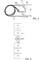
- the Figure 3 shows an exemplary embodiment of a part 09.1 of a multi-part guide segment 09 formed as a structural element on the distal end section 01 of an inner shaft 03.
- the guide segment 09 has a varying wall thickness or thickness S in the circumferential direction U and that the guide segment 09 has different sections with both straight and curved contours in the axial direction or in the direction of the longitudinal axis L.
- Such a final shape of the guide segment 09 can be formed in a particularly advantageous manner by an additive manufacturing process directly on the outer surface 11 of the inner shaft 03, for example by laser deposition welding on the outer shaft 03.
- a preferred multilayer structure of the guide segment 09 is shown in the illustration for reasons of clarity Figure 3 Not shown.
- the Figure 4 shows an exemplary and greatly simplified process sequence of a method according to the invention.
- known individual steps in the context of the manufacture or manufacture of an endoscope in particular in the context of the manufacture of an endoscope with a small outer diameter, preferably ⁇ 4mm, have not been shown for reasons of clarity, but are to be regarded as included in the overall process.
- an inner shaft for receiving imaging optics is provided in a first method step S1.
- a first layer is added in one or more separate areas or sections of the end section of the inner tube with an additive Manufacturing process, for example with laser deposition welding.
- This method step S2 is carried out with the application of further layers, each on the previously formed layer and / or on the outer surface of the inner shaft, until the guide segment is completely formed and in its final shape on the inner shaft and consequently the last layer is applied .
- the guide segment is applied directly to the inner shaft, for example with the formation of a welded connection between the material of the inner shaft on the one hand and the first layer or the first layer of the guide segment on the other.
- the light guide elements of the light guide device are arranged in method step S3 on the outer surface of the inner shaft and in contact with the guide segment.
- the inner shaft together with the light guide elements is introduced into the outer shaft, the radially outer surface of the guide segment coming into contact with the inner surface of the outer shaft. This should take place in the exemplary method step S4.
- the inner shaft and the light guide elements can be fastened in the outer shaft, for example using an adhesion promoter or adhesive, at least in the distal end section of the inner shaft and outer shaft.
Abstract
1. Die Erfindung betrifft ein Verfahren zur Herstellung eines Endoskops (02) mit einer Lichtleitereinrichtung umfassend die Verfahrensschritte:- Bereitstellen eines Innenschaftes (03) zur Aufnahme einer Abbildungsoptik (S1);- Anordnen eines Führungssegmentes (09) zur Ausrichtung des Innenschaftes (03) in einem Außenschaft (04) und/oder zur Führung von Lichtleitelementen (06) der Lichtleitereinrichtung auf der Außenoberfläche (11) des Innenschaftes (03), insbesondere in einem distalen Endabschnitt (01) des Außenschaftes (04);- Anordnen der Lichtleitelemente (06) auf der Außenoberfläche (11) des Innenschaftes (03; S3);- Einführen des Innenschaftes (03) samt Lichtleitelementen (06) in den Außenschaft (04) unter Anlage einer radial äußeren Oberfläche (12) des Führungssegments (09) an einer Innenoberfläche (13) des Außenschafts (04; S4);- Befestigen des Innenschaftes (03) und der Lichtleitelemente (06) im Außenschaft (04), zumindest im distalen Endabschnitt (01) des Innenschaftes (03) und Außenschaftes (04; S5), wobei vorgesehen ist, dass das Führungssegment (09) durch einen additiven Fertigungsprozess unmittelbar auf der Außenoberfläche (11) des Innenschaftes (03) ausgebildet wird (S2).1. The invention relates to a method for producing an endoscope (02) with a light guide device comprising the steps of: - providing an inner shaft (03) for receiving an imaging optics (S1); - arranging a guide segment (09) for aligning the inner shaft (03) in an outer shaft (04) and / or for guiding light guide elements (06) of the light guide device on the outer surface (11) of the inner shaft (03), in particular in a distal end section (01) of the outer shaft (04); ) on the outer surface (11) of the inner shaft (03; S3); - inserting the inner shaft (03) together with light guide elements (06) into the outer shaft (04) with a radially outer surface (12) of the guide segment (09) in contact with an inner surface (13) of the outer shaft (04; S4); - fastening the inner shaft (03) and the light guide elements (06) in the outer shaft (04), at least in the distal end section (01) of the inner shaft (03) and A. outer shaft (04; S5), whereby it is provided that the guide segment (09) is formed directly on the outer surface (11) of the inner shaft (03) by an additive manufacturing process (S2).
Description
Die vorliegende Erfindung betrifft ein Verfahren zum Herstellen eines Endoskops mit einer Lichtleitereinrichtung gemäß dem Oberbegriff des Anspruchs 1. Ferner betrifft die vorliegende Erfindung eine Verwendung eines Verfahrens zur Herstellung eines Endoskops gemäß dem Oberbegriff des Anspruchs 5. Außerdem betrifft die vorliegende Erfindung ein Endoskop mit einer Lichtleitereinrichtung gemäß dem Oberbegriff des Anspruchs 6.The present invention relates to a method for manufacturing an endoscope with a light guide device according to the preamble of claim 1. Furthermore, the present invention relates to a use of a method for manufacturing an endoscope according to the preamble of claim 5. The present invention also relates to an endoscope with a light guide device according to the preamble of claim 6.
In der medizinischen und technischen Endoskopie ist in der Regel eine Beleuchtung des betrachteten Objekts erforderlich. Zur Erzeugung von Beleuchtungslicht mit einem hohen Lichtstrom werden oft separate oder in das proximale Ende des Endoskops integrierte Lichtquelleneinrichtungen verwendet. Vom proximalen Ende zum distalen Ende des Endoskops wird das Beleuchtungslicht mittels eines oder mehrerer Bündel von Lichtleiterelementen einer Lichtleitereinrichtung übertragen.In medical and technical endoscopy, it is usually necessary to illuminate the object being viewed. Light source devices which are separate or integrated into the proximal end of the endoscope are often used to generate illuminating light with a high luminous flux. The illuminating light is transmitted from the proximal end to the distal end of the endoscope by means of one or more bundles of light guide elements of a light guide device.
Im Stand der Technik ist es dabei bekannt, die Lichtleitelemente zwischen einem Außenschaft und einem Innenschaft des Endoskops zum distalen Ende zu führen, wobei der Außenschaft mit seiner Außenoberfläche die äußere Begrenzung des Endoskops mit ausbildet und der Innenschaft zur Aufnahme einer Abbildungsoptik vorgesehen ist.In the prior art, it is known to guide the light guide elements between an outer shaft and an inner shaft of the endoscope to the distal end, the outer shaft with its outer surface also forming the outer boundary of the endoscope and the inner shaft being provided for receiving an imaging optics.
Um eine gewünschte Anordnung des Innenschaftes gegenüber dem Außenschaft zu erreichen oder zu ermöglichen und gleichzeitig eine gewünschte Anordnung und Ausrichtung der Lichtleitelemente im distalen Endabschnitt des Endoskops in seinem fertig oder endgültig montierten Zustand zu ermöglichen, sind aus dem Stand der Technik bereits Führungssegmente oder allgemein Segmente bekannt, die auf der Außenoberfläche des Innenschaftes im distalen Endabschnitt des Innenschaftes angeordnet werden und durch ihre Form in radialer Richtung oder in Umfangsrichtung, insbesondere durch eine variable Höhe oder Dicke in radialer Richtung die Ausrichtung des Innenschaftes gegenüber dem Außenschaft bestimmen, wobei die Erstreckung oder winkelmäßige Ausdehnung des Segments oder Führungssegments in Umfangsrichtung die Position oder Anordnung der Lichtleitelemente im distalen Endabschnitt des Endoskops mitbestimmt und die Form des Segments oder Führungssegments in axialer Richtung, insbesondere an den in Umfangsrichtung liegenden, sich radial erstreckenden Rändern, die Ausrichtung der Lichtleitelemente mitbestimmt.In order to achieve or enable a desired arrangement of the inner shaft with respect to the outer shaft and at the same time enable a desired arrangement and alignment of the light guide elements in the distal end section of the endoscope in its finished or finally assembled state, guide segments or segments in general are already known from the prior art that on the Outer surface of the inner shaft are arranged in the distal end portion of the inner shaft and determine the alignment of the inner shaft relative to the outer shaft by their shape in the radial direction or in the circumferential direction, in particular by a variable height or thickness in the radial direction, the extent or angular extent of the segment or guide segment in the circumferential direction, the position or arrangement of the light guide elements in the distal end portion of the endoscope is determined and the shape of the segment or guide segment in the axial direction, in particular at the circumferential, radially extending edges, the alignment of the light guide elements.
Somit kann zusätzlich zur Relativanordnung zwischen Außenschaft und Innenschaft über die Form des Segments oder Führungssegments die Anordnung und Ausrichtung der Lichtleitelemente im distalen Endabschnitt des Endoskops bestimmt werden, sodass beispielsweise eine gewünschte Ausrichtung, bevorzugt gewinkelt zur axialen Erstreckung des Innen- und/oder Außenschaftes, bei einer gleichzeitig gebündelten oder konzentrierten Anordnung der Lichtleitelemente in einer gleichmäßigen Art und Weise erreicht werden kann.Thus, in addition to the relative arrangement between the outer shaft and the inner shaft, the arrangement and alignment of the light guide elements in the distal end section of the endoscope can be determined via the shape of the segment or guide segment, so that, for example, a desired alignment, preferably angled to the axial extension of the inner and / or outer shaft, can be determined a simultaneously bundled or concentrated arrangement of the light guide elements can be achieved in a uniform manner.
Im Stand der Technik ist zur Erzeugung und/oder Anordnung des Segments oder Führungssegments auf dem Innenschaft in der Regel ein mehrstufiger Prozess oder ein mehrstufiges Verfahren vorgesehen. Dabei wird zunächst einen Rohling oder Grundkörper/Grünkörper des Segments oder Führungssegments im distalen Endabschnitt des Innenschaftes aufgelötet. Diese Vorstufe des endgültigen Führungssegments im Hinblick auf die äußere Form weist in der Regel noch eine gleichmäßige Höhe, Stärke oder radiale Erstreckung auf. Um eine oftmals benötigte oder gewünschte, in Umfangsrichtung variable Höhe oder Stärke des Führungssegments zu erreichen, wird die Baugruppe umfassend den Innenschaft und die Vorstufe des Führungssegments anschließend in einem spanenden Bearbeitungsschritt, bevorzugt durch ein Überdrehen, so bearbeitet, dass die gewünschte Form des Führungssegments, insbesondere die gewünschte in Umfangsrichtung variable Stärke oder Höhe des Führungssegments erreicht wird.In the prior art, a multi-stage process or a multi-stage method is generally provided for generating and / or arranging the segment or guide segment on the inner shaft. First, a blank or base body / green body of the segment or guide segment is soldered onto the distal end section of the inner shaft. This preliminary stage of the final guide segment with regard to the outer shape generally still has a uniform height, thickness or radial extension. In order to achieve a height or thickness of the guide segment that is often required or desired and that is variable in the circumferential direction, the assembly is comprised of the inner shaft and the preliminary stage of the guide segment is then machined in a machining step, preferably by over-turning, so that the desired shape of the guide segment, in particular the desired thickness or height of the guide segment that is variable in the circumferential direction, is achieved.
Allgemein nachteilig an dieser Art der Herstellung oder Bereitstellung der Baugruppe aus Innenschaft und Führungssegment ist einerseits die verhältnismäßig hohe Anzahl an Bearbeitungsschritten. Auch wird im Stand der Technik als Material des Führungselements oftmals Messing eingesetzt, da es sich beim Löten und Überdrehen gut verarbeiten lässt. Die an sich geringe Biokompatibilität und/oder die Einstufung von Messing als Allergen sind jedoch nur tolerierbar, da auf Grund der geringen Fläche oder Oberfläche der Führungselemente die potentiell auslösbaren biochemischen Reaktionen gering sind. Ein weiterer Nachteil besteht insbesondere auch in der bisher bekannten Vorgehensweise zur Befestigung des Rohlings des Führungssegments oder des Verbindens des Innenschaftes mit dem Rohling des Führungssegments. Denn durch das Auflöten unter Verwendung eines Lots als Verbindungsmaterial, können insbesondere bei einem nachfolgenden oder anschließenden mechanischen, bevorzugt spanenden, Bearbeitungsprozess Probleme mit der Haftung auftreten, die im ungünstigsten Fall dazu führen, dass das aufgelötete Führungssegment oder dessen Vorstufe, vom Innenschaft abgesprengt werden oder abplatzen.A general disadvantage of this type of production or provision of the assembly consisting of the inner shaft and the guide segment is, on the one hand, the relatively high number of processing steps. In the prior art, brass is also often used as the material of the guide element, since it can be easily processed during soldering and over-turning. The inherently low biocompatibility and / or the classification of brass as an allergen can only be tolerated, however, since the potentially triggerable biochemical reactions are small due to the small area or surface of the guide elements. Another disadvantage is the previously known procedure for fastening the blank of the guide segment or for connecting the inner shaft to the blank of the guide segment. Because soldering using a solder as the connecting material, problems with adhesion can arise in particular in a subsequent or subsequent mechanical, preferably cutting, machining process, which in the worst case leads to the soldered-on guide segment or its preliminary stage being detached from the inner shaft or flake off.
Der letztgenannte Nachteil tritt besonders bei Endoskopen mit kleinem Durchmesser, insbesondere kleinem Durchmesser des Außenschaftes auf. Bei derartigen Endoskopen kann durch ein Auflöten eines Segments oder einer Vorstufe eines Führungssegments keine ausreichende Haftwirkung erzeugt werden, sodass bei einem nachfolgenden spanenden Bearbeitungsprozess, insbesondere bei einem Überdrehen, die Haftung des Führungssegments am Innenschaft oder auf der Außenoberfläche des Innenschaftes nicht mit ausreichender Reproduzierbarkeit gewährleistet ist.The last-mentioned disadvantage occurs particularly in the case of endoscopes with a small diameter, in particular a small diameter of the outer shaft. In endoscopes of this type, soldering on a segment or a preliminary stage of a guide segment cannot produce a sufficient adhesive effect, so that adhesion in a subsequent machining process, in particular in the case of over-turning of the guide segment on the inner socket or on the outer surface of the inner socket is not guaranteed with sufficient reproducibility.
Diese Problematiken haben insgesamt zu dem Umstand geführt, dass im Stand der Technik für Endoskope mit entsprechend kleinem Durchmesser, insbesondere mit einem Durchmesser des Außenschaftes von ≤4mm, keine entsprechenden Führungssegmente zum Einsatz kommen. Dies wiederum führt jedoch zu besonderen Herausforderungen im Fertigungsprozess der bekannten Endoskope mit geringem Durchmesser. Denn die Anordnung des Innenschaftes gegenüber dem Außenschaft sowie die Anordnung und Ausrichtung der Lichtleitelemente, ganz besonders im distalen Endabschnitt des Endoskops, hängen ohne die Verwendung und die Wirkung eines wie oben beschriebenen Führungssegments ganz wesentlich von der Fertigkeit, insbesondere Fingerfertigkeit des jeweiligen Montagearbeiters ab. Dies führt jedoch dazu, dass nur mit entsprechend hohem Zeitaufwand, unter Einsatz entsprechend versierter Fertigungskräfte und gleichzeitig unter Inkaufnahme nicht unerheblicher Mengen an Ausschuss die bekannten Endoskope mit kleinem Durchmesser produziert werden können.Overall, these problems have led to the fact that in the prior art no corresponding guide segments are used for endoscopes with a correspondingly small diameter, in particular with a diameter of the outer shaft of 4 mm. However, this in turn leads to particular challenges in the manufacturing process of the known endoscopes with a small diameter. Because the arrangement of the inner shaft with respect to the outer shaft as well as the arrangement and alignment of the light guide elements, especially in the distal end section of the endoscope, without the use and the effect of a guide segment as described above, depend to a large extent on the skill, in particular the dexterity of the assembly worker. However, this leads to the fact that the known endoscopes with a small diameter can only be produced with a correspondingly high expenditure of time, with the use of appropriately experienced production workers and at the same time accepting not inconsiderable amounts of rejects.
Der vorliegenden Erfindung liegt daher die Aufgabe zu Grunde die vorangehend genannten Nachteile im Stand der Technik zu überwinden und insbesondere ein Endoskop und ein Verfahren zur Herstellung eines Endoskops, sowie eine Verwendung des Verfahrens vorzuschlagen, die eine schnelle, sichere und zuverlässige Anordnung eines bekannten Führungssegments auf der Außenoberfläche des Innenschaftes des Endoskops erlauben.The present invention is therefore based on the object of overcoming the aforementioned disadvantages in the prior art and in particular to propose an endoscope and a method for producing an endoscope, as well as a use of the method, which provide a fast, safe and reliable arrangement of a known guide segment allow the outer surface of the inner shaft of the endoscope.
Im Hinblick auf das erfindungsgemäße Verfahren wird die oben genannte Aufgabe mit den Merkmalen des Anspruchs 1 gelöst. Bezüglich der Verwendung des Verfahrens wird die erfindungsgemäße Aufgabe mit den Merkmalen des Anspruchs 5 gelöst. Im Hinblick auf ein erfindungsgemäßes Endoskop wird die Aufgabe mit den Merkmalen des Anspruchs 6 gelöst. Bevorzugte Ausführungsformen sind jeweils Gegenstand der Unteransprüche.With regard to the method according to the invention, the above-mentioned object is achieved with the features of claim 1. With regard to the use of the method, the object of the invention is achieved with the Features of claim 5 solved. With regard to an endoscope according to the invention, the object is achieved with the features of claim 6. Preferred embodiments are in each case the subject matter of the subclaims.
Das erfindungsgemäße Verfahren zur Herstellung eines Endoskops mit einer Lichtleitereinrichtung sieht zunächst folgende an sich bekannte Verfahrensschritte vor:
- Bereitstellen eines Innenschaftes zur Aufnahme einer Abbildungsoptik;
- Anordnen eines Führungssegments zur Ausrichtung des Innenschaftes in einem Außenschaft und/oder zur Führung von Lichtleitelementen der Lichtleitereinrichtung auf der Außenoberfläche des Innenschaftes, insbesondere in einem distalen Endabschnitt des Innenschaftes;
- Anordnen der Lichtleitelemente auf der Außenoberfläche des Innenschaftes;
- Einführen des Innenschaftes samt Lichtleitelementen in den Außenschaft unter Anlage einer radial äußeren Oberfläche des Führungssegments an einer Innenoberfläche des Außenschaftes.
- Befestigen des Innenschaftes und der Lichtleitelemente im Außenschaft, zumindest im distalen Endabschnitt des Innenschaftes und Außenschaftes.
- Providing an inner shaft for receiving imaging optics;
- Arranging a guide segment for aligning the inner shaft in an outer shaft and / or for guiding light guide elements of the light guide device on the outer surface of the inner shaft, in particular in a distal end section of the inner shaft;
- Arranging the light guide elements on the outer surface of the inner shaft;
- Introducing the inner shaft together with the light guide elements into the outer shaft with a radially outer surface of the guide segment resting on an inner surface of the outer shaft.
- Fastening the inner shaft and the light guide elements in the outer shaft, at least in the distal end section of the inner shaft and outer shaft.
Erfindungsgemäß ist dabei jedoch vorgesehen, dass das Führungssegment durch einen additiven Fertigungsprozess unmittelbar auf der Außenoberfläche des Innenschaftes ausgebildet wird. Dies bedeutet mit anderen Worten ausgedrückt, dass insbesondere kein Lot oder sonstiges Verbindungsmaterial abgesehen von dem Material des Innenschaftes und dem Material des Führungssegments bei der Befestigung oder Verbindung zum Einsatz kommt. Wie später noch ausführlicher dargelegt werden wird, ist es zwar möglich, dass sich in einem Übergangsbereich zwischen dem Material des Innenschaftes und dem Material des Führungssegments ein Mischmaterial oder eine Übergangszone ausbildet, die dann beide Materialien und/oder Mischungen der beiden Materialien aufweist, es wird jedoch bei der unmittelbaren Aufbringung des Führungssegments auf dem Innenschaft kein weiteres Material, wie beispielsweise Lot, verwendet.According to the invention, however, it is provided that the guide segment is formed directly on the outer surface of the inner shaft by an additive manufacturing process. In other words, this means that in particular no solder or other connecting material apart from the material of the inner shaft and the material of the guide segment is used in the fastening or connection. As will be explained in more detail later, Although it is possible that a mixed material or a transition zone is formed in a transition area between the material of the inner shaft and the material of the guide segment, which then has both materials and / or mixtures of the two materials, however, when the guide segment is directly applied No other material, such as solder, is used for the inner shaft.
Die Grundidee der vorliegenden Erfindung basiert also auf dem Verbinden des Führungssegments mit dem Material des Führungssegments unmittelbar auf der Außenoberfläche des Innenschaftes, wozu ein entsprechender additiver Fertigungsprozess verwendet wird. Dadurch kann die Haftung des Führungssegments auf dem Innenschaft deutlich verbessert werden. Gleichzeitig können Prozessschritte vereinfacht werden oder sogar wegfallen, da das Führungssegment unmittelbar auf der Außenoberfläche des Innenschafts ausgebildet wird ohne das Befestigungsmaterial oder Mittlerschichten eines weiteren Materials erzeugt und/oder angebracht oder aufgebracht werden müssen. Durch die unmittelbare oder direkte Aufbringung und Ausbildung des Führungssegments auf dem Innenschaft, insbesondere auf dessen Außenoberfläche wird zudem eine besonders langlebige Verbindung zwischen Innenschaft und Führungssegment erzeugt.The basic idea of the present invention is therefore based on connecting the guide segment to the material of the guide segment directly on the outer surface of the inner shaft, for which purpose a corresponding additive manufacturing process is used. As a result, the adhesion of the guide segment to the inner socket can be significantly improved. At the same time, process steps can be simplified or even omitted, since the guide segment is formed directly on the outer surface of the inner shaft without the fastening material or middle layers of a further material having to be produced and / or attached or applied. The direct or direct application and formation of the guide segment on the inner shaft, in particular on its outer surface, also creates a particularly long-lasting connection between the inner shaft and the guide segment.
Gemäß einer ersten vorteilhaften Ausführungsform des Verfahrens kann vorgesehen sein, dass das Führungssegment in seiner endgültigen Form, insbesondere in seiner endgültigen geometrischen Form, auf der Außenoberfläche des Innenschafts ausgebildet wird. Dadurch wird das Verfahren zur Herstellung der Baugruppe umfassend den Innenschaft und das Führungssegment weiter vereinfacht. Insbesondere können separate Herstellungsprozesse, die gegebenenfalls einen Werkzeugwechsel erfordern oder zumindest den Wechsel zwischen Werkzeugstationen notwendig machen, wegfallen. Denn im Gegensatz zum Auflöten des Führungssegments mit anschließendem Überdrehen oder spanendem Bearbeiten, kann bei der Ausbildung des Führungssegments durch einen additiven Fertigungsprozess unmittelbar auf der Außenoberfläche des Innenschaftes die endgültige Form oder die endgültige geometrische Form des Führungssegmentes unmittelbar also direkt erzeugt werden, sodass gerade kein weiterer Bearbeitungsschritt oder keine weiteren Bearbeitungsmaßnahmen der Baugruppe umfassend das Führungssegment und den Innenschaft nach Aufbringen des Führungssegmentes mehr notwendig sind.According to a first advantageous embodiment of the method, it can be provided that the guide segment is formed in its final shape, in particular in its final geometric shape, on the outer surface of the inner shaft. This further simplifies the method for producing the assembly comprising the inner shaft and the guide segment. In particular, separate manufacturing processes, which may require a tool change or at least make a change between tool stations necessary, can be omitted. Because in contrast to soldering the Guide segment with subsequent overturning or machining, when the guide segment is formed by an additive manufacturing process, the final shape or the final geometric shape of the guide segment can be generated directly on the outer surface of the inner shaft, so that no further processing step or further processing measures are taken Assembly comprising the guide segment and the inner shaft after applying the guide segment are more necessary.
Eine weitere bevorzugte Ausgestaltung des Verfahrens sieht zudem vor, dass das Führungssegment mittels Laserauftragsschweißen, insbesondere von Material, welches sich mit dem Material des Innenschaftes, bevorzugt Monel verbindet, auf dem Innenschaft ausgebildet wird. Das Laserauftragsschweißen (laser metal deposition: LMD) hat im Hinblick auf die vorliegende Anwendung besondere Vorteile. Einerseits kann auch auf komplexen Oberflächen, insbesondere auch auf stark gekrümmten Oberflächen eine gleichmäßige Erzeugung eines Gegenstands gewährleistet werden. Weiter wird durch das Laserauftragsschweißen in einem Bereich unmittelbar angrenzend an das Substrat oder das Material, auf welches aufgeschweißt wird, im vorliegenden Fall also der Oberfläche des Innenschaftes ein Schmelzbad erzeugt, in dem die Materialien miteinander vermischen oder ineinander übergehen, sodass eine besonders starke und dauerhafte Verbindung zwischen dem mit dem Laserauftragsschweißen hergestellten Gegenstand und dem Untergrund oder Substrat erzeugt wird. Das aufgebrachte oder aufgetragene Material kann dabei in erster Linie anhand seiner Verbindungseigenschaften mit dem Material des Innenschaftes ausgewählt werden und zusätzlich in Hinblick auf eine Biokompatibilität gewählt werden. Die Eignung zur nachträglichen Bearbeitbarkeit kann vernachlässigt werden, da durch das erfindungsgemäße Verfahren die Möglichket eröffnet wird ohne Nachbearbeitungsschritte, insbesondere spanende Bearbeitungen zu verzichten. Dadurch kann mit dem Verfahren gemäß der vorliegenden Erfindung auch auf Messing als Material für das Führungssegment verzichtet werden.A further preferred embodiment of the method also provides that the guide segment is formed on the inner shaft by means of laser deposition welding, in particular of material which connects to the material of the inner shaft, preferably Monel. Laser metal deposition (LMD) has particular advantages with regard to the present application. On the one hand, a uniform production of an object can also be guaranteed on complex surfaces, in particular also on strongly curved surfaces. Furthermore, the laser build-up welding creates a weld pool in an area directly adjacent to the substrate or the material that is being welded, in the present case the surface of the inner shaft, in which the materials mix with one another or merge into one another, so that a particularly strong and durable Connection between the object produced with the laser deposition welding and the underground or substrate is generated. The applied or applied material can be selected primarily on the basis of its connection properties with the material of the inner shaft and can also be selected with a view to biocompatibility. The suitability for subsequent processability can be neglected, since the method according to the invention opens up the possibility of without Post-processing steps, in particular machining, to be dispensed with. As a result, brass can also be dispensed with as the material for the guide segment with the method according to the present invention.
Eine weitere Ausführungsvariante des erfindungsgemäßen Verfahrens sieht vor, dass das Führungssegment als mehrschichtiges, bevorzugt mehrteiliges, Strukturelement auf der Außenoberfläche des Innenschaftes ausgebildet wird. Durch eine mehrschichtige Ausbildung des Führungssegments kann besonders vorteilhaft eine, beispielsweise in Umfangsrichtung variierende Stärke oder Dicke des Führungssegments dadurch realisiert werden, dass in unterschiedlichen Bereichen in Umfangsrichtung unterschiedlich viele Schichten mittels des additiven Fertigungsprozesses, beispielsweise Laserauftragsschweißen, erzeugt werden. Dadurch kann besonders vorteilhaft das Führungssegment in seiner endgültigen Form direkt erzeugt werden, ohne das nachfolgende Bearbeitungsschritte oder Umformungsprozesse notwendig sind. Besonders vorteilhaft kann das Führungssegment mehrteilig ausgestaltet sein. Auch bei klassischen Führungssegmenten, die zunächst in einer Vorstufe oder einem Rohling aufgelötet und dann mittels Überdrehen in die endgültige Form gebracht werden, kann die Dicke oder Stärke des Führungssegments in manchen Bereichen bis auf 0 oder nahezu 0 reduziert werden, sodass nach dem Auflöten einer einzigen oder zusammenhängenden Vorstufe im Endeffekt zwei nahezu oder zwei tatsächlich voneinander separierte Abschnitte des Führungssegments auf der Außenoberfläche des Innenschaftes ausgebildet werden. Diese Art des Überdrehens ist eine weitere besondere Anforderung an den Herstellungsprozess bekannter Führungssegmente, weil bei dem Reduzieren der Stärke oder der Dicke des Führungssegments in Bereichen in Umfangsrichtung bis auf nahezu 0 oder bis auf 0 besondere Anforderungen an den Bearbeitungsschritt selbst sowie an die Verbindung zwischen Führungssegment und Innenschaft gewährleistet sein müssen. Durch die direkte und unmittelbare Ausbildung des Führungssegments als mehrteilige Form oder Geometrie, kann auf die entsprechenden Verfahrensschritte verzichtet werden, was ebenfalls die Voraussetzung für die Ausbildung in das Führungssegments herabsetzt oder vereinfacht.A further variant embodiment of the method according to the invention provides that the guide segment is designed as a multi-layer, preferably multi-part, structural element on the outer surface of the inner shaft. With a multilayer design of the guide segment, a thickness or thickness of the guide segment that varies, for example, in the circumferential direction can be realized particularly advantageously by producing a different number of layers in different areas in the circumferential direction by means of the additive manufacturing process, for example laser deposition welding. As a result, the guide segment can be produced directly in its final form in a particularly advantageous manner, without the need for subsequent machining steps or reshaping processes. The guide segment can particularly advantageously be configured in several parts. Even with classic guide segments, which are first soldered on in a preliminary stage or a blank and then brought into the final shape by over-turning, the thickness of the guide segment can be reduced in some areas to 0 or almost 0, so that after soldering a single or contiguous preliminary stage, in the end two virtually or two actually separated sections of the guide segment are formed on the outer surface of the inner shaft. This type of overturning is another special requirement for the manufacturing process of known guide segments, because when reducing the strength or the thickness of the guide segment in areas in the circumferential direction down to almost 0 or down to 0, special requirements are placed on the machining step itself and on the connection must be guaranteed between the guide segment and the inner shaft. Due to the direct and immediate design of the guide segment as a multi-part shape or geometry, the corresponding process steps can be dispensed with, which also reduces or simplifies the prerequisites for the design in the guide segment.
Im Hinblick auf die Verwendung des vorangehend beschriebenen Verfahrens wird die oben genannte Aufgabe dadurch gelöst, dass das beschriebene Verfahren bei der Herstellung eines Endoskops zum Einsatz kommt oder Verwendung findet, welches einen Außenschaft mit einem Außendurchmesser von ≤4mm bevorzugt von ≤3mm besonders bevorzugt von ≤2mm, aufweist.With regard to the use of the method described above, the above-mentioned object is achieved in that the described method is used or is used in the production of an endoscope which has an outer shaft with an outer diameter of 4 mm, preferably 3 mm, particularly preferably 2mm.
Grundsätzlich lassen sich vorteilhaft mit dem oben genannten Verfahren auch Führungssegmente auf Innenschäften von Endoskopen mit größerem Außendurchmesser herstellen. Wie oben bereits beschrieben kann unabhängig von den Durchmessern bei dem erfindungsgemäßen Verfahren bereits eine Vielzahl von Vorteilen gegenüber dem stand der Technik realisieren. Besonders hervorzuheben ist jedoch die Verwendung im Rahmen der Herstellung von Endoskopen mit kleinem Außendurchmesser, insbesondere mit kleinem Außendurchmesser gemäß den vorangehend genannten Grenzen. Denn wie eingangs bereits beschrieben, war die Verwendung von Führungssegmenten oder die Aufbringung von Führungssegmenten für derart kleine oder dünne Endoskope bisher nicht oder zumindest nicht mit den bekannten Methoden und Verfahren möglich.In principle, the above-mentioned method can also advantageously be used to produce guide segments on the inner shafts of endoscopes with a larger outer diameter. As already described above, regardless of the diameters, the method according to the invention can already achieve a large number of advantages over the prior art. Particularly noteworthy, however, is the use in the context of the production of endoscopes with a small external diameter, in particular with a small external diameter in accordance with the aforementioned limits. Because, as already described at the beginning, the use of guide segments or the application of guide segments for such small or thin endoscopes has not previously been possible, or at least not possible with the known methods and processes.
Damit erlaubt die Verwendung erstmals in einem kompakten und wirtschaftlich sinnvollen Verfahren mit einer entsprechend hohen Zuverlässigkeit die Ausbildung oder Anordnung von Führungssegmenten auf der Außenoberfläche von Innenschäften von Endoskopen, die insgesamt nach der Montage einen Außendurchmesser von ≤4mm aufweisen.Thus, for the first time in a compact and economically sensible process with a correspondingly high level of reliability, the use allows the formation or arrangement of guide segments on the outer surface of inner shafts of endoscopes, which have an overall outside diameter of ≤4mm after assembly.
Besonders vorteilhaft kann die Verwendung des vorangehend beschriebenen Verfahrens bei Endoskopen zum Einsatz kommen, für die im Innenschaft, auf dem das Führungssegment angeordnet oder ausgebildet wird, eine Stablinse zur Übertragung der Bildinformationen zum Einsatz kommt.The use of the method described above can be used particularly advantageously in endoscopes for which a rod lens is used to transmit the image information in the inner shaft on which the guide segment is arranged or formed.
Die oben genannte Aufgabe wird im Hinblick auf ein Endoskop mit einer Lichtleitereinrichtung umfassend einen Innenschaft zur Aufnahme einer Abbildungsoptik, wobei auf dem Innenschaft ein Führungssegment zur Ausrichtung des Innenschaftes in einem Außenschaft und/oder zur Führung von Lichtleitelementen der Lichtleitereinrichtung auf der Außenoberfläche des Innenschaftes, insbesondere in einem distalen Endabschnitt des Außenschaftes angeordnet ist und wobei die Lichtleitelemente zwischen der Außenoberfläche des Innenschaftes und einer Innenoberfläche des Außenschaftes zu einem distalen Ende des Endoskops verlaufen und wobei das Endoskop ferner Befestigungsmittel zum Befestigen des Innenschaftes und der Lichtleitelemente im Außenschaft, zumindest im distalen Endabschnitt des Innenschaftes und Außenschaftes aufweist dadurch gelöst, dass das Führungssegment durch einen additiven Fertigungsprozess unmittelbar auf der Außenoberfläche des Innenschaftes angeordnet ist.The above-mentioned object is achieved with regard to an endoscope with a light guide device comprising an inner shaft for receiving imaging optics, a guide segment on the inner shaft for aligning the inner shaft in an outer shaft and / or for guiding light guide elements of the light guide device on the outer surface of the inner shaft, in particular is arranged in a distal end portion of the outer shaft and wherein the light guide elements between the outer surface of the inner shaft and an inner surface of the outer shaft to a distal end of the endoscope and wherein the endoscope furthermore fastening means for fastening the inner shaft and the light guide elements in the outer shaft, at least in the distal end portion of the The inner shaft and the outer shaft are achieved in that the guide segment is arranged directly on the outer surface of the inner shaft by means of an additive manufacturing process.
Durch die unmittelbare Ausbildung oder Aufbringung des Führungssegmentes auf der Außenoberfläche des Innenschaftes wird eine ausreichende Festigkeit oder eine ausreichende Stabilität der Verbindung zwischen Innenschaft und Führungssegment ermöglicht.The direct formation or application of the guide segment on the outer surface of the inner shaft enables sufficient strength or sufficient stability of the connection between the inner shaft and the guide segment.
Vorteilhaft kann diese unmittelbare Verbindung mit einem additiven Fertigungsprozess erreicht werden, wodurch insgesamt Fertigungsschritte oder Herstellungsschritte gegenüber dem bekannten Stand der Technik entfallen können.This direct connection can advantageously be achieved with an additive manufacturing process, as a result of which manufacturing steps or manufacturing steps can be omitted compared to the known prior art.
Bezüglich der Vorteile und vorteilhaften Wirkungen der erfindungsgemäßen Ausführung des Endoskops wird auch auf die vorangehende Beschreibung des entsprechend analogen erfindungsgemäßen Verfahrens verwiesen. In diesem Zusammenhang sei erwähnt, dass soweit erforderlich verfahrensmäßig offenbarte Merkmale auch als Vorrichtungsmerkmale offenbart gelten sollen und umgekehrt.With regard to the advantages and advantageous effects of the embodiment of the endoscope according to the invention, reference is also made to the preceding description of the correspondingly analogous method according to the invention. In this context, it should be mentioned that, if necessary, features disclosed in terms of the method should also apply as disclosed device features, and vice versa.
Gemäß einer ersten, besonders vorteilhaften Ausführung des Endoskops kann vorgesehen sein, dass das Endoskop ein Außenschaft aufweist, der einen Außendurchmesser von ≤4mm, bevorzugt von ≤3mm, besonders bevorzugt von ≤2mm aufweist. Durch die direkte Ausbildung des Führungssegments mittels eines additiven Verdünnungsprozesses auf der Außenoberfläche des Innenschaftes kann für derart kleine beziehungsweise dünne Endoskope erstmals zuverlässig die Anordnung eines Führungssegmentes auf dem Innenschaft ermöglicht werden und dadurch erstmals die Anordnung und Ausrichtung der Lichtleitelemente, insbesondere im distalen Endabschnitt des Endoskops, zuverlässig und reproduzierbar gewährleistet werden, sodass die Anforderungen an die Arbeitsschritte im Fertigungs- oder Montageprozess, insbesondere die Anforderungen an Montagearbeiterinnen und Montagearbeiter geringer ausfallen kann, da nicht mehr in ganz überwiegender Mehrheit die Präzision und die Erfahrung der Montagearbeiterinnen und Montagearbeiter über die Anordnung und Ausrichtung der Lichtleitelemente sowie über die Anordnung des Innenschaftes im Außenschaftes entscheidet.According to a first, particularly advantageous embodiment of the endoscope, it can be provided that the endoscope has an outer shaft which has an outer diameter of 4 mm, preferably 3 mm, particularly preferably 2 mm. The direct formation of the guide segment by means of an additive thinning process on the outer surface of the inner shaft makes it possible for the first time reliably to arrange a guide segment on the inner shaft for such small or thin endoscopes and thus for the first time to arrange and align the light guide elements, in particular in the distal end section of the endoscope, be guaranteed reliably and reproducibly, so that the requirements for the work steps in the manufacturing or assembly process, in particular the requirements for assembly workers, can be lower, as the precision and experience of assembly workers with regard to the arrangement and alignment is no longer the overwhelming majority the light guide elements as well as the arrangement of the inner shaft in the outer shaft.
Gemäß einer weiteren vorteilhaften Ausführung des Endoskops kann zudem vorgesehen sein, dass das Führungssegment aus Material, gebildet ist,welches sich mit dem Material des Innenschaftes, bevorzugt Monel verbindet, welches bevorzugt durch Laserauftragsschweißen, mit dem Material des Innenschaftes verbunden ist. Wie oben bereits ausgeführt, kann dadurch die Materialauswahl optimiert werden, da kein oder nur geringer Wert aus eine Nachbearbeitbarkeit des Materials des Führungssegments gelegt werden muss.According to a further advantageous embodiment of the endoscope, it can also be provided that the guide segment is formed from material that connects to the material of the inner shaft, preferably Monel, which is preferably connected to the material of the inner shaft by laser deposition welding. As already stated above, the choice of material can be optimized in this way, since little or no value has to be placed on reworkability of the material of the guide segment.
Eine weitere besonders bevorzugte Ausgestaltung des Endoskops kann vorsehen, dass das Führungssegment als mehrschichtiges, bevorzugt mehrteiliges Strukturelement auf der Außenoberfläche des Innenschaftes ausgebildet ist. Dadurch wird ermöglicht, dass das Führungssegment durch die Mehrschichtigkeit die, im additiven Fertigungsprozess bevorzugt abbildbar ist, die gewünschte Form, insbesondere die gewünschte Außenform und gegebenenfalls variierende Stärken oder Dicken, abhängig von der Orientierung in Umfangsrichtung, unmittelbar erzeugt oder ausgebildet wird, sodass sowohl die Führung und Ausrichtung der Lichtleitelemente, als auch die Ausrichtung des Innenschaftes im Außenschaft gewährleistet wird. Die mehrschichtige und gegebenenfalls mehrteilige Ausbildung als Strukturelement ermöglicht zudem eine genaue, gegebenenfalls exzentrische Orientierung des Innenschaftes im Außenschaft.Another particularly preferred embodiment of the endoscope can provide that the guide segment is designed as a multi-layer, preferably multi-part structural element on the outer surface of the inner shaft. This enables the guide segment to be created or formed directly, depending on the orientation in the circumferential direction, depending on the orientation in the circumferential direction, so that both the Guiding and alignment of the light guide elements, as well as the alignment of the inner shaft in the outer shaft is guaranteed. The multi-layer and possibly multi-part design as a structural element also enables precise, possibly eccentric orientation of the inner socket in the outer socket.
Eine weitere bevorzugte Ausführungsform des Endoskops sieht vor, dass dieses eine im Innenschaft angeordnete Optik aufweist, die ihrerseits wiederrum eine Stablinse zur Übertragung von Bildinformationen umfasst.Another preferred embodiment of the endoscope provides that it has optics arranged in the inner shaft, which in turn comprise a rod lens for the transmission of image information.
Vorteilhafte Ausführungsformen und Wirkungsweisen der vorangehend beschriebenen Erfindung werden nachfolgend anhand der Figuren, die lediglich schematisch gehalten sind, dargestellt und erläutert.Advantageous embodiments and modes of operation of the invention described above are illustrated and explained below with reference to the figures, which are only kept schematic.
Darin zeigen:
- Fig. 1:
- Eine schematische Darstellung eines distalen Endabschnitts eines Endoskops gemäß dem Stand der Technik;
- Fig. 2:
- Eine schematische Darstellung eines distalen Endabschnitts eines Endoskops gemäß der vorliegenden Erfindung;
- Fig. 3:
- Eine schematische Darstellung eines distalen Endabschnitts eines Innenschaftes zur Verwendung in dem erfindungsgemäßen Verfahren;
- Fig. 4:
- Eine schematische Darstellung eines Ablaufdiagramms des erfindungsgemäßen Verfahrens.
- Fig. 1:
- A schematic representation of a distal end section of an endoscope according to the prior art;
- Fig. 2:
- A schematic representation of a distal end portion of an endoscope according to the present invention;
- Fig. 3:
- A schematic representation of a distal end section of an inner shaft for use in the method according to the invention;
- Fig. 4:
- A schematic representation of a flow chart of the method according to the invention.
Im Zwischenraum 05 zwischen Innenschaft 03 und Außenschaft 04 sind die Enden von Lichtleitelementen 06 zu erkennen, die beispielsweise als gebündelte Lichtleitfasern oder Lichtleiter ausgebildet sind. Die Lichtleitelemente 06 sind in der Darstellung der Fig. aus Gründen der Übersichtlichkeit deutlich größer/stärker dargestellt als in der Realität. In der
Die
Genau diese Ausbildung oder Anordnung eines Führungssegments 09 ist, wie in
Die
Das Führungssegment 09 ist dabei als mehrschichtiges und mehrteiliges Strukturelement ausgebildet, was durch die Schichten 10 und die einzelnen Teile 09.1 und 09.2 angedeutet wird. Die einzelnen Schichten 10 werden in einem additiven Fertigungsprozess, beispielsweise in einem Laserauftragsschweißverfahren erzeugt, wobei das Führungssegment 09 derart erzeugt wird, dass es in seiner endgültigen Form und insbesondere ohne weitere Nachbearbeitungsschritte unmittelbar auf der Außenoberfläche 11 des Innenschaftes 03 ausgebildet und/oder angeordnet wird. Damit kann insbesondere für Endoskope 02 mit kleinem Durchmesser ein spanender Bearbeitungsschritt, bevorzugt zur Ausbildung der unterschiedlichen Stärken S des Führungssegments 09 in Umfangsrichtung U unterbleiben oder wegfallen. Es ist deutlich erkennbar, dass die Verteilung der Lichtelemente 06 gegenüber der
Die
Die
In dem erfindungsgemäß relevanten Abschnitt des gesamten Herstellungsprozesses oder Herstellungsverfahren wird in einem ersten Verfahrensschritt S1 ein Innenschaft zur Aufnahme einer Abbildungsoptik bereitgestellt. In einem nachfolgenden Verfahrensschritt S2 wird in Abschnitten oder Bereichen des distalen Endabschnitts des Innenschaftes eine erste Lage in einem oder mehreren voneinander getrennten Bereichen oder Abschnitten des Endabschnitts des Innenrohrs mit einem additiven Fertigungsprozess, beispielsweise mit Laserauftragsschweißen ausgebildet. Dieser Verfahrensschritt S2 wird mit dem Auftrag von weiteren Schichten, jeweils auf der vorangehend ausgebildeten Schicht und/oder auf der Außenoberfläche des Innenschaftes, solange ausgeführt, bis das Führungssegment vollständig und in seiner endgültigen Form auf dem Innenschaft ausgebildet ist und folglich die letzte Schicht aufgetragen ist. Dabei erfolgt in besonders vorteilhafter Weise eine unmittelbare Aufbringung des Führungssegments auf dem Innenschaft, beispielsweise unter Ausbildung einer Schweißverbindung zwischen dem Material des Innenschaftes einerseits und der ersten Lage oder der ersten Schicht des Führungssegments andererseits.In the section of the entire manufacturing process or manufacturing method that is relevant according to the invention, an inner shaft for receiving imaging optics is provided in a first method step S1. In a subsequent method step S2, in sections or areas of the distal end section of the inner shaft, a first layer is added in one or more separate areas or sections of the end section of the inner tube with an additive Manufacturing process, for example with laser deposition welding. This method step S2 is carried out with the application of further layers, each on the previously formed layer and / or on the outer surface of the inner shaft, until the guide segment is completely formed and in its final shape on the inner shaft and consequently the last layer is applied . In a particularly advantageous manner, the guide segment is applied directly to the inner shaft, for example with the formation of a welded connection between the material of the inner shaft on the one hand and the first layer or the first layer of the guide segment on the other.
Nach der rekursiven Ausbildung des Führungssegments auf dem Innenschaft im Rahmen des Verfahrensschritt S2 erfolgt im Verfahrensschritt S3 die Anordnung der Lichtleitelemente der Lichtleitereinrichtung auf der Außenoberfläche des Innenschaftes sowie in Anlage an das Führungssegment. In einem nachfolgenden Verfahrensschritt wird der Innenschaft samt Lichtleitelementen in de Außenschaft eingeführt, wobei die radial äußere Oberfläche des Führungssegments an der Innenoberfläche des Außenschafts zur Anlage kommt. Dies soll im beispielhaften Verfahrensschritt S4 erfolgen.After the recursive formation of the guide segment on the inner shaft as part of method step S2, the light guide elements of the light guide device are arranged in method step S3 on the outer surface of the inner shaft and in contact with the guide segment. In a subsequent process step, the inner shaft together with the light guide elements is introduced into the outer shaft, the radially outer surface of the guide segment coming into contact with the inner surface of the outer shaft. This should take place in the exemplary method step S4.
Im nachfolgenden Verfahrensschritt S5 kann, beispielsweise unter Verwendung eines Haftvermittlers oder Klebstoffs eine Befestigung des Innenschaftes und der Lichtleitelemente im Außenschaft, zumindest im distalen Endabschnitt des Innenschaftes und Außenschaftes erfolgen.In the subsequent method step S5, the inner shaft and the light guide elements can be fastened in the outer shaft, for example using an adhesion promoter or adhesive, at least in the distal end section of the inner shaft and outer shaft.
- 0101
- distalen Endabschnittdistal end section
- 0202
- Endoskopendoscope
- 0303
- InnenschaftInner socket
- 0404
- AußenschaftOuter socket
- 0505
- ZwischenraumSpace
- 0606
- LichtleitelementLight guide element
- 0707
- Bereicharea
- 0808
- BefestigungsmittelFasteners
- 0909
- FührungssegmentLeadership segment
- 09.109.1
- erster Teilfirst part
- 09.209.2
- zweiter Teilsecond part
- 1010
- Schichtlayer
- 1111
- Außenoberfläche des InnenschaftesOuter surface of the inner socket
- 1212th
- Außenoberfläche des FührungssegmentsOuter surface of the guide segment
- 1313th
- Innenoberfläche des AußenschaftesInner surface of the outer shaft
- WW.
- WandstärkeWall thickness
- SS.
- Dicke des Führungssegments (radial)Thickness of the guide segment (radial)
- UU
- UmfangsrichtungCircumferential direction
- LL.
- Längsrichtung (Innenschaft und Außenschaft)Longitudinal direction (inner socket and outer socket)
- S1 - S5S1 - S5
- VerfahrensschritteProcedural steps
Claims (10)
dass das Führungssegment (09) durch einen additiven Fertigungsprozess unmittelbar auf der Außenoberfläche (11) des Innenschaftes (03) ausgebildet wird (S2).Method for producing an endoscope (02) with a light guide device comprising the method steps:
that the guide segment (09) is formed directly on the outer surface (11) of the inner shaft (03) by an additive manufacturing process (S2).
dadurch gekennzeichnet,
dass das Führungssegment (09) in seiner endgültigen Form auf der Außenoberfläche des Innenschaftes (11) ausgebildet wird.Method according to claim 1,
characterized,
that the guide segment (09) is formed in its final shape on the outer surface of the inner shaft (11).
dadurch gekennzeichnet,
dass das Führungssegment (09) mittels Laserauftragsschweißen (laser metal deposition, "LMD"), insbesondere von Material, welches sich mit dem Material des Innenschaftes, bevorzugt Monel, verbindet, auf dem Innenschaft (03) ausgebildet wird.Method according to claim 1 or 2,
characterized,
that the guide segment (09) is formed on the inner shaft (03) by means of laser metal deposition ("LMD"), in particular of material which connects to the material of the inner shaft, preferably Monel.
dadurch gekennzeichnet,
dass das Führungssegment (09) als mehrschichtiges, bevorzugt mehrteiliges, Strukturelement auf der Außenoberfläche des Innenschaftes (11) ausgebildet wird.Method according to one of Claims 1 to 3,
characterized,
that the guide segment (09) is designed as a multi-layer, preferably multi-part, structural element on the outer surface of the inner shaft (11).
dadurch gekennzeichnet,
dass das Endoskop (02) einen Außenschaft (04) mit einem Außendurchmesser von ≤4mm, bevorzugt mit ≤3mm, besonders bevorzugt mit ≤2mm aufweist.Use of the method according to one of Claims 1 to 4 for the production of an endoscope (02),
characterized,
that the endoscope (02) has an outer shaft (04) with an outer diameter of ≤4mm, preferably ≤3mm, particularly preferably ≤2mm.
dadurch gekennzeichnet,
dass das Führungssegment (09) durch einen additiven Fertigungsprozess unmittelbar auf der Außenoberfläche des Innenschaftes (11) angeordnet ist.Endoscope (02) with a light guide device comprising an inner shaft (03) for receiving imaging optics, a guide segment (09) on the inner shaft (03) for aligning the inner shaft (03) in an outer shaft (04) and / or for guiding light guide elements (06) of the light guide device is arranged on the outer surface of the inner shaft (11), in particular in a distal end section (01) of the outer shaft (04), and wherein the light guide elements (06) are located between the outer surface of the inner shaft (11) and an inner surface of the outer shaft ( 13) run to a distal end of the endoscope (02) and wherein the endoscope (02) remote fastening means (08) for fastening the The inner shaft (03) and the light guide elements (06) in the outer shaft (04), at least in the distal end section of the inner shaft (03) and outer shaft (04),
characterized,
that the guide segment (09) is arranged directly on the outer surface of the inner shaft (11) by an additive manufacturing process.
dadurch gekennzeichnet,
dass der Außenschaft (04) des Endoskops (02) einen Außendurchmesser von ≤4mm, bevorzugt mit ≤3mm, besonders bevorzugt mit ≤2mm, aufweist.Endoscope (02) according to claim 6,
characterized,
that the outer shaft (04) of the endoscope (02) has an outer diameter of ≤4mm, preferably ≤3mm, particularly preferably ≤2mm.
dadurch gekennzeichnet,
dass das Führungssegment (09) aus Material gebildet ist, welches, bevorzugt durch Laserauftragsschweißen, mit dem Material des Innenschaftes (03), bevorzugt Monel, verbunden ist.Endoscope (02) according to claim 6 or 7,
characterized,
that the guide segment (09) is formed from material which, preferably by laser deposition welding, is connected to the material of the inner shaft (03), preferably Monel.
dadurch gekennzeichnet,
dass das Führungssegment (09) als mehrschichtiges, bevorzugt mehrteiliges, Strukturelement auf der Außenoberfläche des Innenschaftes (11) ausgebildet ist.Endoscope (02) according to one of Claims 6 to 8,
characterized,
that the guide segment (09) is designed as a multi-layer, preferably multi-part, structural element on the outer surface of the inner shaft (11).
dadurch gekennzeichnet,
dass eine im Innenschaft (03) angeordnete Optik des Endoskops (02) eine Stablinse aufweist.Endoscope (02) according to one of Claims 6 to 9,
characterized,
that an optic of the endoscope (02) arranged in the inner shaft (03) has a rod lens.
Applications Claiming Priority (1)
| Application Number | Priority Date | Filing Date | Title |
|---|---|---|---|
| DE102020105469.6A DE102020105469A1 (en) | 2020-03-02 | 2020-03-02 | Endoscope with a light guide device, method for producing an endoscope with a light guide device and use of a method for producing an endoscope |
Publications (1)
| Publication Number | Publication Date |
|---|---|
| EP3875020A1 true EP3875020A1 (en) | 2021-09-08 |
Family
ID=74672085
Family Applications (1)
| Application Number | Title | Priority Date | Filing Date |
|---|---|---|---|
| EP21158031.1A Pending EP3875020A1 (en) | 2020-03-02 | 2021-02-19 | Endoscope with an optical waveguide device, method for manufacturing an endoscope with an optical waveguide device and use of a method for manufacturing an endoscope |
Country Status (3)
| Country | Link |
|---|---|
| US (1) | US20210271069A1 (en) |
| EP (1) | EP3875020A1 (en) |
| DE (1) | DE102020105469A1 (en) |
Citations (3)
| Publication number | Priority date | Publication date | Assignee | Title |
|---|---|---|---|---|
| JP2001017381A (en) * | 1999-07-05 | 2001-01-23 | Olympus Optical Co Ltd | Endoscope |
| US20110040151A1 (en) * | 2009-08-14 | 2011-02-17 | Jan Dahmen | Positioning clip |
| DE102017104188A1 (en) * | 2017-02-28 | 2018-08-30 | Cl Schutzrechtsverwaltungs Gmbh | Method for producing a medical component |
Family Cites Families (6)
| Publication number | Priority date | Publication date | Assignee | Title |
|---|---|---|---|---|
| US5573493A (en) | 1993-10-08 | 1996-11-12 | United States Surgical Corporation | Endoscope attachment for changing angle of view |
| DE10307903A1 (en) * | 2003-02-18 | 2004-09-02 | Karl Storz Gmbh & Co. Kg | Method for mounting an endoscope |
| DE102005051209A1 (en) * | 2005-10-18 | 2007-04-19 | Karl Storz Gmbh & Co. Kg | Endoscope consists of a shaft with outer and inner pipe that house a shorter intermediate pipe and has channel to hold fibre optic |
| US9402643B2 (en) | 2008-01-15 | 2016-08-02 | Novartis Ag | Targeted illumination for surgical instrument |
| EP3539444A4 (en) * | 2016-11-10 | 2019-11-20 | Kyocera Corporation | Body cavity observation system, trocar device, and method of operating body cavity observation system |
| US10695043B2 (en) * | 2017-02-21 | 2020-06-30 | Katalyst Surgical, Llc | Surgical instrument subcomponent integration by additive manufacturing |
-
2020
- 2020-03-02 DE DE102020105469.6A patent/DE102020105469A1/en active Pending
-
2021
- 2021-02-19 US US17/180,030 patent/US20210271069A1/en active Pending
- 2021-02-19 EP EP21158031.1A patent/EP3875020A1/en active Pending
Patent Citations (3)
| Publication number | Priority date | Publication date | Assignee | Title |
|---|---|---|---|---|
| JP2001017381A (en) * | 1999-07-05 | 2001-01-23 | Olympus Optical Co Ltd | Endoscope |
| US20110040151A1 (en) * | 2009-08-14 | 2011-02-17 | Jan Dahmen | Positioning clip |
| DE102017104188A1 (en) * | 2017-02-28 | 2018-08-30 | Cl Schutzrechtsverwaltungs Gmbh | Method for producing a medical component |
Also Published As
| Publication number | Publication date |
|---|---|
| DE102020105469A1 (en) | 2021-09-02 |
| US20210271069A1 (en) | 2021-09-02 |
Similar Documents
| Publication | Publication Date | Title |
|---|---|---|
| EP2132024B1 (en) | Compensation element for connecting components | |
| EP2151185B1 (en) | Laryngoscope applicator | |
| WO2008025623A1 (en) | Method for welding components with a closed hollow cross-section in such a way that a peripheral gap is produced between the two overlapping components | |
| EP2853187B1 (en) | Manufacture of an endoscope with a light conducting device | |
| EP1757381A2 (en) | Method and device for the rotationally secure connection of a hollow axle with a part | |
| DE10239393A1 (en) | Shaft-hub connection for transmission has boring with two adjacent sectors of different diameters | |
| WO2015086243A2 (en) | Transmission shaft and method and device for the production thereof | |
| EP2006591A1 (en) | Compensation element for pipes | |
| DE102016221705B4 (en) | Gear from a gear assembly and method for producing a gear assembly | |
| EP3875020A1 (en) | Endoscope with an optical waveguide device, method for manufacturing an endoscope with an optical waveguide device and use of a method for manufacturing an endoscope | |
| EP2483027B1 (en) | Method for producing an internal toothing | |
| DE19715016A1 (en) | Two-part housing and method for its manufacture | |
| EP0390768A1 (en) | Bone implant | |
| DE102015105069B4 (en) | Method for connecting at least two components of an endoscope | |
| DE102006038932A1 (en) | Compensation gearing device used in a motor vehicle comprises a joint with a press fit region and a gap region facing an access side before welding | |
| DE2548853A1 (en) | METHOD AND DEVICE FOR MANUFACTURING RING-SHAPED METAL BLANKS | |
| DE102011081067A1 (en) | Endoscope and method of manufacturing a distal end of an endoscope | |
| DE10341853B4 (en) | Metal hose and method of making a metal hose | |
| DE102007040843A1 (en) | Laser processing head for machining a workpiece by means of a laser beam | |
| DE102005028004B4 (en) | Method for producing a gear | |
| EP3769135A1 (en) | Method for centering optical elements | |
| DE102020109867B4 (en) | Intraocular lens injector with a specific piercing tip of a hollow needle | |
| EP3479918B1 (en) | Method for producing an inner tube and a device for cutting and aspirating tissue | |
| EP3208011B1 (en) | Tangential thread rolling head | |
| DE102012105727A1 (en) | Rod lens units for rod lens system for rigid and flexible endoscope, have case in which rod lens is arranged, where proximal and distal edges of case are not flush with proximate and distal ends of rod lens |
Legal Events
| Date | Code | Title | Description |
|---|---|---|---|
| PUAI | Public reference made under article 153(3) epc to a published international application that has entered the european phase |
Free format text: ORIGINAL CODE: 0009012 |
|
| STAA | Information on the status of an ep patent application or granted ep patent |
Free format text: STATUS: THE APPLICATION HAS BEEN PUBLISHED |
|
| AK | Designated contracting states |
Kind code of ref document: A1 Designated state(s): AL AT BE BG CH CY CZ DE DK EE ES FI FR GB GR HR HU IE IS IT LI LT LU LV MC MK MT NL NO PL PT RO RS SE SI SK SM TR |
|
| STAA | Information on the status of an ep patent application or granted ep patent |
Free format text: STATUS: REQUEST FOR EXAMINATION WAS MADE |
|
| 17P | Request for examination filed |
Effective date: 20220117 |
|
| RBV | Designated contracting states (corrected) |
Designated state(s): AL AT BE BG CH CY CZ DE DK EE ES FI FR GB GR HR HU IE IS IT LI LT LU LV MC MK MT NL NO PL PT RO RS SE SI SK SM TR |
|
| P01 | Opt-out of the competence of the unified patent court (upc) registered |
Effective date: 20230527 |
|
| STAA | Information on the status of an ep patent application or granted ep patent |
Free format text: STATUS: EXAMINATION IS IN PROGRESS |
|
| 17Q | First examination report despatched |
Effective date: 20230726 |