EP3875003A1 - Zubereitungsgefäss mit einer verriegelungseinrichtung - Google Patents
Zubereitungsgefäss mit einer verriegelungseinrichtung Download PDFInfo
- Publication number
- EP3875003A1 EP3875003A1 EP20161437.7A EP20161437A EP3875003A1 EP 3875003 A1 EP3875003 A1 EP 3875003A1 EP 20161437 A EP20161437 A EP 20161437A EP 3875003 A1 EP3875003 A1 EP 3875003A1
- Authority
- EP
- European Patent Office
- Prior art keywords
- pot
- locking
- lid
- preparation vessel
- actuating
- Prior art date
- Legal status (The legal status is an assumption and is not a legal conclusion. Google has not performed a legal analysis and makes no representation as to the accuracy of the status listed.)
- Granted
Links
Images








Classifications
-
- A—HUMAN NECESSITIES
- A47—FURNITURE; DOMESTIC ARTICLES OR APPLIANCES; COFFEE MILLS; SPICE MILLS; SUCTION CLEANERS IN GENERAL
- A47J—KITCHEN EQUIPMENT; COFFEE MILLS; SPICE MILLS; APPARATUS FOR MAKING BEVERAGES
- A47J43/00—Implements for preparing or holding food, not provided for in other groups of this subclass
- A47J43/04—Machines for domestic use not covered elsewhere, e.g. for grinding, mixing, stirring, kneading, emulsifying, whipping or beating foodstuffs, e.g. power-driven
- A47J43/07—Parts or details, e.g. mixing tools, whipping tools
- A47J43/075—Safety devices
- A47J43/0761—Safety devices for machines with tools driven from the lower side
- A47J43/0772—Safety devices for machines with tools driven from the lower side activated by the proper positioning of the cover
-
- A—HUMAN NECESSITIES
- A47—FURNITURE; DOMESTIC ARTICLES OR APPLIANCES; COFFEE MILLS; SPICE MILLS; SUCTION CLEANERS IN GENERAL
- A47J—KITCHEN EQUIPMENT; COFFEE MILLS; SPICE MILLS; APPARATUS FOR MAKING BEVERAGES
- A47J36/00—Parts, details or accessories of cooking-vessels
- A47J36/06—Lids or covers for cooking-vessels
- A47J36/10—Lid-locking devices
-
- A—HUMAN NECESSITIES
- A47—FURNITURE; DOMESTIC ARTICLES OR APPLIANCES; COFFEE MILLS; SPICE MILLS; SUCTION CLEANERS IN GENERAL
- A47J—KITCHEN EQUIPMENT; COFFEE MILLS; SPICE MILLS; APPARATUS FOR MAKING BEVERAGES
- A47J43/00—Implements for preparing or holding food, not provided for in other groups of this subclass
- A47J43/04—Machines for domestic use not covered elsewhere, e.g. for grinding, mixing, stirring, kneading, emulsifying, whipping or beating foodstuffs, e.g. power-driven
- A47J43/046—Machines for domestic use not covered elsewhere, e.g. for grinding, mixing, stirring, kneading, emulsifying, whipping or beating foodstuffs, e.g. power-driven with tools driven from the bottom side
-
- A—HUMAN NECESSITIES
- A47—FURNITURE; DOMESTIC ARTICLES OR APPLIANCES; COFFEE MILLS; SPICE MILLS; SUCTION CLEANERS IN GENERAL
- A47J—KITCHEN EQUIPMENT; COFFEE MILLS; SPICE MILLS; APPARATUS FOR MAKING BEVERAGES
- A47J43/00—Implements for preparing or holding food, not provided for in other groups of this subclass
- A47J43/04—Machines for domestic use not covered elsewhere, e.g. for grinding, mixing, stirring, kneading, emulsifying, whipping or beating foodstuffs, e.g. power-driven
- A47J43/07—Parts or details, e.g. mixing tools, whipping tools
- A47J43/0716—Parts or details, e.g. mixing tools, whipping tools for machines with tools driven from the lower side
-
- A—HUMAN NECESSITIES
- A47—FURNITURE; DOMESTIC ARTICLES OR APPLIANCES; COFFEE MILLS; SPICE MILLS; SUCTION CLEANERS IN GENERAL
- A47J—KITCHEN EQUIPMENT; COFFEE MILLS; SPICE MILLS; APPARATUS FOR MAKING BEVERAGES
- A47J43/00—Implements for preparing or holding food, not provided for in other groups of this subclass
- A47J43/04—Machines for domestic use not covered elsewhere, e.g. for grinding, mixing, stirring, kneading, emulsifying, whipping or beating foodstuffs, e.g. power-driven
- A47J43/07—Parts or details, e.g. mixing tools, whipping tools
- A47J43/0727—Mixing bowls
-
- A—HUMAN NECESSITIES
- A47—FURNITURE; DOMESTIC ARTICLES OR APPLIANCES; COFFEE MILLS; SPICE MILLS; SUCTION CLEANERS IN GENERAL
- A47J—KITCHEN EQUIPMENT; COFFEE MILLS; SPICE MILLS; APPARATUS FOR MAKING BEVERAGES
- A47J43/00—Implements for preparing or holding food, not provided for in other groups of this subclass
- A47J43/04—Machines for domestic use not covered elsewhere, e.g. for grinding, mixing, stirring, kneading, emulsifying, whipping or beating foodstuffs, e.g. power-driven
- A47J43/07—Parts or details, e.g. mixing tools, whipping tools
- A47J43/075—Safety devices
- A47J43/0761—Safety devices for machines with tools driven from the lower side
Definitions
- the invention relates to a preparation vessel for connection to a receiving area of a basic device of an electric motor-operated kitchen appliance, the preparation vessel having a pot, a pot base that can be connected to the receiving area and a lid closing a pot opening of the pot.
- the invention also relates to an electric motor-operated kitchen appliance, in particular a mixer, with a base device and a preparation vessel which can be connected to a receiving area of the base device and which has a pot and a lid that closes a pot opening.
- Preparation vessels and kitchen machines with a preparation vessel are known in the prior art.
- the housing of the food processor can, for example, have a vessel receiving area in which the preparation vessel can be inserted, the vessel receiving area preferably being designed at least in relation to a partial area corresponding to the shape of the preparation vessel in such a way that the preparation vessel in the course of being connected to the vessel receiving area both in relation to a vertical one Direction, as well as in relation to a circumferential direction of the preparation vessel can be aligned.
- a rotary shaft can be arranged in the receiving area, which shaft is used to drive one in the preparation vessel located agitator is used.
- the agitator is driven by an electric motor on the kitchen machine.
- the preparation vessel has a lid which can be locked on the pot by means of a locking device.
- a kitchen appliance known in the prior art with a locking device for the lid of the preparation vessel is shown, for example, in the patent EP 2 813 165 B1 .
- the locking device has two locking parts which overlap a pot rim and a lid rim and are designed as locking rollers rotating about an essentially horizontal axis. The locking rollers can be rotated from a release position to a locking position and vice versa.
- the preparation vessel has a locking device with a locking element for locking the pot to the lid, the pot base having at least one actuating element for actuating the locking device, the actuating element being arranged on the pot foot in such a way that it is supported by a corresponding actuating device of the receiving area of the kitchen appliance can be actuated.
- the locking device which is used to lock the lid to the pot, is located on the preparation vessel itself.
- the preparation vessel according to the invention is designed by the actuating element provided on the pot base in such a way that the locking device of the preparation vessel can be actuated by means of an actuation device of the kitchen appliance receiving the preparation vessel.
- the actuating element is preferably located on the underside of the preparation vessel, so that when the preparation vessel is connected to the receiving area of the base device, it comes into contact with an element of the actuation device on the kitchen machine.
- the locking device can have as a locking element, for example, correspondingly designed bayonet locking elements on the pot and the lid and on one of the bayonet locking elements z.
- B. provide a toothing in which a portion of a drive element engages in order to close the two bayonet locking elements relative to one another rotate.
- the bayonet lock can bring about an axial displacement of the lid in the direction of the pot, in particular through, for example, a ramp-shaped design of one of the corresponding bayonet lock elements, so that the lid is pressed onto the edge of the pot opening and thus a firm and, in particular, fluid-tight closure of the preparation vessel takes place.
- the locking device for locking the lid to the pot belongs exclusively to the preparation vessel and an interface is only arranged on the base of the preparation vessel, which allows actuation of the locking device of the preparation vessel by an actuating device of a basic appliance of a food processor .
- the interface is preferably located under the preparation vessel, ie in the area of an essentially horizontal contact surface between the receiving area of the base device and the base of the pot of the preparation vessel, so that the preparation vessel can be shaped very differently, in particular with regard to its height and / or diameter . Compatibility between different preparation vessels and different basic devices of a kitchen appliance is thus facilitated.
- the locking device have a drive device that drives the locking element and is in mechanical operative connection with the actuating element.
- the drive device of the preparation vessel serves to transmit mechanical forces from an actuating device of a kitchen appliance to the locking element of the locking device of the preparation vessel.
- the actuating device of the food processor can for example have an electric motor which drives the actuating element of the preparation vessel directly or preferably with the interposition of a gear acts on the actuator.
- the gear of the kitchen appliance can for example have a plurality of toothed elements, for example a spur gear and a worm gear, and act on the actuating element of the preparation vessel with a gear element driven last in the chain of effects.
- the actuating element of the preparation vessel for example a toothed wheel arranged in the base of the preparation vessel, is part of the vessel-side drive device which is in mechanical operative connection with the actuation device of the kitchen appliance.
- the actuating element of the preparation vessel finally transmits the drive force via the drive device to the locking element, which locks the lid on the pot.
- the drive device can have a drive element which, starting from the pot base up to the lid, is guided through a wall of the pot and / or a handle of the pot.
- the drive element can in particular be a rotary shaft.
- the locking device can be made from a particularly small number of individual parts.
- the actuating element of the locking device in the pot base can be directly connected to the drive element, which then acts on the locking element in the region of the vessel opening in order to finally lock the lid with the pot.
- a rotary shaft is particularly suitable as a drive element since it can be integrated into a wall of the pot and / or a handle of the pot in a space-saving manner.
- a cavity can be provided in the wall of the pot or in the handle be, within which the drive element, preferably a rotary shaft, extends.
- the drive element preferably the rotary shaft, can act on the locking element of the locking device in the region of the pot opening.
- a partial area of the drive element can have a toothing which engages in a corresponding toothing of the locking element.
- the locking element can be a locking ring rotatably mounted on the pot or the lid, surrounding the pot opening in a closed state by means of the lid, the locking element being assigned a drive device which is set up to rotate the locking element around the pot opening.
- the locking ring can for its part, for example, directly bring about a locking between the pot and the lid or first act on an intermediate element which then brings about the locking.
- the locking ring can, for example, provide an element of a bayonet lock and / or provide a link with ramps or the like, which enable, in particular, an axial displacement of the cover relative to the pot.
- the lid can be pressed or pulled onto the pot and, in particular, braced in such a way that a fluid-tight locking of the pot is ensured.
- the locking element is not connected to the pot or the lid in a fixed manner, but rather rotatable relative to the latter. As a result, only the locking element has to be rotated by the drive device, and not the entire cover, for example. This makes it possible to use lighter and / or smaller components or an electric motor with lower power for the drive device of the preparation vessel and also the actuator of the food processor, which saves weight and costs in the manufacture of the preparation vessel and / or the kitchen machine.
- the locking element have at least one active element which is designed to cause an axial displacement of the lid towards the pot (5) and / or a radially outwardly acting bracing of the lid when the locking element rotates.
- an active element can be, for example, a ramp which is formed in the locking direction on the locking element designed as a locking ring.
- the locking element has a guide slot along which a corresponding partial area of the lid or the pot can slide.
- an active element can also be, for example, a partial element of a bayonet catch, a partial area of the locking element engaging into a corresponding opening in the lid or the pot.
- the active element is designed so that when the locking element rotates, the cover is axially displaced relative to the pot and / or the cover is braced in a radially outward direction.
- the active element of the locking element contacts the relevant part of the lid or pot and pushes the lid into the desired locking position.
- the active element forms a guide element of a guide device or guide slot.
- the locking element can also be an elastic locking ring which is rotatably mounted on the pot and, when rotated, expands along a link of the pot and is additionally displaced axially in the longitudinal extension of the pot. When expanding, the locking ring dips into an undercut of the lid, for example, and moves it into a locking position.
- the locking ring can also have sub-elements which are movably mounted on a base body and which can be displaced radially outward during rotation.
- the locking ring can also be slotted in relation to one or more peripheral subareas, so that a corresponding link element can at least intermittently engage in the locking ring and thereby cause a change in the diameter of the locking ring.
- the active element can be engaged in a corresponding opening in the lid or the pot to form a bayonet lock, the active element or a portion of the lid or the pot having a ramp that rises in the direction of locking rotation and that axially displaces the lid causes relative to the pot and thus a locking of the pot with the lid.
- the active element forms a sub-element of a bayonet lock.
- the corresponding element of the bayonet lock is a part of the lid or the pot with an opening. The active element engages into the opening and, when the locking element rotates, follows a rising ramp, which results in an axial displacement of the cover relative to the pot.
- the ramp can be formed on the active element itself, with a partial area of the active element reaching through the opening of the lid or the pot in the sense of a bayonet lock and another partial area of the active element having the ramp or on a corresponding ramp of the lid or the pot slides along.
- the active element and the ramp can also be designed locally separated from one another, the active element only having the function of engaging the openings of the bayonet lock, and the ramp ensuring that the lid is braced relative to the pot. In this sense, two equally effective embodiments are possible.
- the rotating locking ring can be mounted on the pot of the preparation vessel and engage in corresponding bayonet contours of the lid and thereby pull the lid in the direction of the pot.
- the rotating locking element be a locking ring mounted on the lid, which engages in corresponding bayonet contours of the pot and thus displaces the lid in the direction of the pot.
- the correct functioning of the bayonet lock depends on the lid being placed on the pot in a directed manner, so that corresponding elements of the bayonet lock can interlock.
- the pot and / or the cover preferably have stop elements which serve as an anti-twist device.
- the corresponding bayonet elements of the bayonet catch can be equipped with end stops.
- the lid is correctly placed on the pot at the beginning of the locking movement, it is possible to rotate the locking ring until an end stop on the corresponding bayonet element is reached. If the cover is not placed correctly, for example at an angle, it is not possible to rotate the locking ring up to the end stop. If no lid is placed on the pot, the locking ring can be rotated beyond a defined amount, since the locking ring does not hit a stop element. By evaluating a current rotational position of the locking ring, it can thus be determined whether a lid has been placed on the pot or whether the lid is correctly locked to the pot.
- An alternative embodiment of the invention can provide that the pot or the lid has an intermediate element movably mounted on the pot or the lid, the active element of the locking element being formed, the intermediate element against a rotation of the locking element in the axial and / or radial direction To press part of the lid or the pot and thereby lock the pot with the lid.
- the lid is not locked directly to the pot by means of the locking element.
- Much more the active element of the locking element acts first on an intermediate element, which then causes the locking between the lid and the pot.
- the locking can be achieved reliably regardless of a rotational position of the lid on the pot.
- the convenience for the user is increased, since this embodiment allows reliable locking even when the lid is placed on the pot in an undirected manner.
- the intermediate element can be mounted movably in the axial and / or radial direction on the pot or cover, the cover placed on the pot initially pushing the intermediate element away in the radial and / or axial direction so that it in turn falls onto a corresponding portion of the cover or . of the pot acts and thus causes a lock between the pot and the lid.
- the locking element can preferably have a plurality of link elements in the circumferential direction, which act in the manner of a link guide on one or more intermediate elements.
- the active element of the locking element provides a guide slot which, upon contact with the intermediate element and continued rotation of the locking element in the locking direction, causes a displacement of the intermediate element both in the radial direction and in the axial direction.
- the intermediate element can first be displaced in a radial direction pointing outward relative to the inside of the pot, the intermediate element engaging behind an undercut formed on the cover. With continued rotation of the locking element, the intermediate element is then displaced in the longitudinal direction of the pot by a corresponding shaping of the active element. The intermediate element takes the cover with it until it reaches an end position. To unlock the cover again, the locking ring can be rotated, for example, in the opposite direction, the intermediate element being moved out of the end position again by means of a return spring, ie moving in the direction of the locking element and the cover being released.
- the backward movement of the intermediate element is possible also possible by means of a slotted guide, or by means of a combination of a return spring and a slotted guide.
- the intermediate element can in particular be mounted on the pot or the cover such that it can pivot in the axial and / or radial direction.
- the intermediate element is a second rotation ring to the locking ring, which can be manipulated by means of the locking ring, for example in such a way that the annular intermediate element initially expands upon contact with the locking ring and rotates in the locking direction and is then displaced in the axial direction so that the intermediate ring engages, for example, in an undercut of the lid or the pot when it is expanded, and then displaces the lid in the axial direction into a locking position.
- a detection mechanism can be used to determine whether the lid is actually on the pot and has been locked correctly.
- the detection mechanism can include, for example, a detection lever that interacts with the locking ring. The detection lever can be pressed against the locking ring by a spring.
- the locking ring has a recess. If the cover is not in a suitable position for locking, the spring presses the detection lever into the recess of the locking ring so that the locking ring is blocked and cannot be rotated. If the cover has been locked correctly, the detection lever is pressed down by an edge of the cover so that the detection lever cannot engage in the recess of the locking ring. The locking ring can then continue to rotate unhindered.
- a rotational angle of the locking ring can be recorded and evaluated, for example by determining a number of revolutions of a rotational shaft of a drive motor of the actuating device of the kitchen appliance.
- a blocked locking ring can also be detected, for example, by evaluating a motor current.
- the Locking ring blocked before a defined rotational position is reached. This state is interpreted as a faulty locking state. If the cover is correctly placed, however, the locking ring can continue to rotate until the defined rotational position is exceeded. This state is then interpreted as a correctly locked cover.
- the preparation vessel can have a guide slot arranged on the pot with an engaging element mounted in a spiral guide track of the guide slot, the guide track running around a spiral axis pointing radially outward in relation to the interior of the pot, and wherein a rotation of the locking element an axial and radial displacement of the engaging element along the spiral guide track to a portion of the lid causes until a portion of the engaging element pointing out of the guide slot rests on the lid, thus locking the pot with the lid.
- the lid can be placed on the pot in any rotational position.
- the guide link for effecting the locking is not assigned to the locking ring, but is arranged on the pot.
- An engagement element is guided in the guide slot, which is manipulated by the rotating locking ring, namely in such a way that the engagement element is forced through the guide track and is simultaneously displaced both in a radial direction and in an axial direction of the pot.
- the displaced engagement element acts along its displacement path on a corresponding partial area of the cover and thereby locks the Cover with the pot by moving the cover in the axial direction towards the pot and bracing it with it.
- the invention also proposes an electric motor-operated kitchen appliance, in particular a mixer, the kitchen appliance having a base device and a preparation vessel which can be connected to a receiving area of the base device and which has a pot and a lid that closes a pot opening the preparation vessel is further designed according to one of the embodiments described above and the base device has an actuating device which is set up to actuate the locking device of the preparation vessel when the base device and preparation vessel are connected to one another.
- the features and advantages of the preparation vessel thus also result correspondingly for the electric motor-operated kitchen appliance. Overall, a kitchen appliance is thus created which can be operated with a large number of differently designed preparation vessels.
- the preparation vessel according to the invention now provides its own locking device, so that the basic appliance of the kitchen appliance no longer has to have a locking device for the preparation vessel.
- the pot of the preparation vessel can have a large number of different heights and can still be connected to the base device in such a way that the lid can be optimally locked to the pot.
- the pot is designed in any case so that its pot base has an actuating element for actuating the locking device of the preparation vessel, an actuating device arranged in the base device corresponding to the actuating element and being able to actuate it.
- the basic device preferably has an electric motor with an associated gear as the actuation device, which acts on the actuating element of the locking device and thus causes the lid to be locked to the pot.
- the kitchen appliance has a safety device for locking the preparation vessel on the basic appliance of the kitchen machine, the safety device having a safety element movably mounted on the preparation vessel, which can be moved behind an undercut of the basic appliance, or wherein the safety device is attached to the Base device has movably mounted securing element which is movable behind an undercut of the preparation vessel, the actuating device of the base device being designed to drive the securing element of the securing device at the same time and in addition to actuating the locking device.
- the actuation mechanism for the lid lock can thus also be used at the same time to lock the preparation vessel on the base device.
- a projection or an undercut can be arranged on the gear of the actuating device of the basic device, which, at a certain angle of rotation of a gear element, engages in a counter-contour attached to the pot. Depending on the angle of rotation of the gear element, the pot can then either be separated from the base device or remain firmly connected to it.
- a projection or an undercut can also be arranged on a partial area of the preparation vessel, for example on a movable element of the drive device of the preparation vessel.
- FIG. 1 shows a food processor 4 with a base device 3, which has a receiving area 2 for connection to a preparation vessel 1.
- the basic device 3 of the kitchen appliance 4 has a display 27 for displaying functions of the kitchen appliance 4 and, if necessary, recipes that can be prepared by the kitchen appliance 4.
- the preparation vessel 1 has a pot 5 with a handle 16 and a pot base 6, which is used to connect to the receiving area 2 of the food processor 4, and a lid 8 with a lid opening 29 and a lid handle 30. For example, ingredients can be passed through the lid opening 29 be entered in the pot 5 of the preparation vessel 1.
- the Figures 2 and 3 show in detail a locking device 9 of the preparation vessel 1, by means of which the pot 5 and the lid 8 of the preparation vessel 1 can be locked to one another.
- the receiving area 2 of the base device 3 of the food processor 4 has an actuating device 12 for acting on an actuating element 11 of the locking device 9 of the preparation vessel 1, so that the kitchen machine 4 can actuate a locking mechanism of the preparation vessel 1 in order to lock the lid 8 to the pot 5 .
- the actuating device 12 of the food processor 4 has here, for example, in detail an electric motor 40 which drives a spur gear 39 and a worm gear 38 connected to it.
- the worm gear 38 in turn acts on a coupling element 31 of the basic device 3.
- the coupling element 31 has a toothing 36 which can engage in the worm gear 38.
- the coupling element 31 is used for coupling with the actuating element 11 of the
- Preparation vessel 1 The actuating element 11 of the locking device 9 in turn acts on a drive device 13 which drives a locking element 10 of the locking device 9 that is rotatably mounted on the pot 5 in the circumferential direction.
- the locking element 10 cannot be displaced in the axial direction of the pot 5.
- the axial displacement is prevented here, for example, by a collar 49 formed on the pot opening 7 and the handle 16 of the pot 5.
- the drive device 13 has a drive element 14, which is in the form of a rotary shaft, for example.
- the rotary shaft is guided through a wall 15 of the handle 16 of the preparation vessel 1 and extends up to the level of a pot opening 7 of the pot 5, on which the locking element 10 of the locking device 9 is located.
- the locking element 10 is designed as a bayonet ring.
- the bayonet ring has active elements 17 for locking the lid 8 to the pot 5, which elements can engage in corresponding bayonet openings 41 of the lid 8.
- the locking element 10 also has a toothing 37, which corresponds to a toothing of the drive element 14, not shown, so that when the drive element 14 rotates, the locking element 10 rotates about the pot opening 7.
- corresponding stop elements can be provided on the pot 5 and lid 8, for example in the area of the handle 16 and the lid handle 30.
- the invention according to this exemplary embodiment of a locking device 9 of a preparation vessel 1 functions in such a way that a user connects the preparation vessel 1 to the base device 3 of the kitchen appliance 4. This results in a coupling between the coupling element 31 of the receiving area 2 of the kitchen appliance 4 and the actuating element 11 of the locking device 9 of the preparation vessel 1.
- the electric motor 40 assigned to the locking device 9 drives the food processor 4 the spur gear 39, the worm gear 38 and the coupling element 31 of the food processor 4, so that there is a rotation of the actuating element 11 and thus also of the drive element 14 of the drive device 13 for the locking element 10.
- the lid 8 is placed on the pot 5, the user already has the lid handle 30 and the handle 16 superimposed on one another (see FIG Figure 1 ) brought.
- the active elements 17 of the locking element 10 are positioned in the vicinity of the bayonet openings 41 of the cover 8.
- the drive device 13 of the preparation vessel 1 now rotates the locking element 10 and thus also displaces the active elements 17 relative to the bayonet openings 41 of the lid 8 until an end position and thus also the bayonet lock between the corresponding partial areas of the pot 5 and lid 8 is reached.
- the active elements 17 of the locking element 10 (or alternatively the lid 8) preferably have ramps 18 which cause the lid 8 to be pulled axially in the direction of the pot opening 7 and thus press the lid 8 onto the pot 5 and lock it.
- the locking element 10 namely the bayonet ring, can also be arranged on the cover 8 instead of on the pot 5.
- the Figures 6 to 8 show a schematic diagram of the in Figure 4 shown bayonet lock between pot 5 and cover 8, wherein the cover 8 has ramps 18, on which the active element 17 of the locking element 10 can slide along.
- Figure 6 shows a partial area of the cover 8 with a bayonet opening 41, which is used to receive the active element 17 of the locking element 10.
- the active element 17 is still completely next to the ramp 18 of the lid 8.
- the lid 8 is, however, placed in an optimal starting position on the pot 5, so that the active element 17 of the locking element 10 is positioned at the foot of the ramp 8 that the active element 17 on the basis of this, when the locking element 10 rotates, it can slide onto the ramp 18 and finally as in FIG Figure 7 shown through the bayonet opening 41 protrudes.
- a nose 44 of the active element 17 extends beyond the top of the lid 8 and pulls the lid 8 downward in the direction of the pot 5.
- Figure 8 shows a situation in which the cover 8 does not rest properly, for example at a slight angle, on the pot 5 and thus also on the locking element 10.
- the active element 17 strikes a side edge 50 of the ramp 18, so that the active element 17 cannot be rotated to the left and thus cannot reach the ramp 18. It is therefore not possible for the user to rotate the locking element 10 any further and to close the bayonet lock.
- the cover 8 is completely absent, the locking element 10 can be rotated relative to the pot 5 beyond a defined maximum dimension, since the nose 44 of the active element 17 does not strike an edge of the bayonet opening 41 of the cover 8.
- a detection device which detects a rotation path or angle of rotation of the locking element 10 or the active element 17 relative to the pot 5, can then use the amount of rotation to determine whether the lid 8 has been properly connected to the pot 5 or not. If it is determined that a lock has failed, a corresponding warning can be output to the user, for example via the display 27 of the kitchen appliance 4.
- the Figures 9 to 12 show a preparation vessel 1 according to the invention according to a further possible embodiment.
- the preparation vessel 1 also has a pot 5, a lid 8 and a locking device 9 for locking the pot 5 to the lid 8.
- the locking device 9 has a locking element 10, which is also designed as a rotatable ring which is rotatably mounted on the pot 5.
- the locking device 9 furthermore has an intermediate element 19 that can be manipulated by means of the locking element 10.
- the intermediate element 19 is a pivotable lever which is mounted pivotably about a pivot axis 34 on the pot 5 and has a projection 42 formed on a free end region which, as in FIG Figures 10b and 11b can be seen to grip behind a collar 46 of the cover 8.
- the projection 42 is located on the free end region of the intermediate element 19, which faces away from the pivot axis 34.
- the mounting of the intermediate element 19 on the pivot axis 34 enables both a pivoting parallel to the wall 15 of the pot 5 and a pivoting away from the wall 15, the projection 42 on the pot 5 being positioned outward.
- the intermediate element 19 is also assigned a detection device 33 which is set up to detect a locked state between the pot 5 and the lid 8.
- a hold-down 35 is also assigned to the intermediate element 19, as well as a return spring 32 (see FIG Figure 12a ), which acts on the intermediate element 19 with a restoring force in relation to the rotation about the pivot axis 34, which force acts in the direction of the locking element 10.
- the design of the locking device 9 with the participation of an intermediate element 19 allows the pot 5 to be locked to the lid 8 even when the user places the lid 8 on the pot 5 in any rotational position.
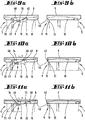
- FIG. 9b, 10b and 11b each a 90 ° rotated view of the preparation vessel 1 according to FIG Figures 9a, 10a and 11a represent. Only one intermediate element 19 is shown in each case, wherein the pot 5 can also have a plurality of intermediate elements 19 which are arranged in the circumferential direction of the pot 5 and which interact with the locking element 10.
- the locking element 10 is, for example, as before with respect to FIG Figures 2 and 3 explained driven by a drive device 13, which in turn is driven by an actuating device 12 of a base device 3 of the food processor 4.
- the locking element 10 has, in particular in the Figure 12a recognizable guide contours 51 which cause the intermediate element 19 to pivot about the pivot axis 34 when the locking element 10 rotates relative to the pot 5 and thus also relative to the intermediate element 19.
- the guide contours 51 include, inter alia, a paragraph 45 (see Figure 12a ) of the locking element 10, on which the detection device 33 slides when the lid 8 is properly placed on the pot 5 and thus detects that the user has properly placed the lid 8 on the pot 5.
- the cover 8 is fixed by means of the intermediate element 19, which is as in the Figures 11a and 11b shown is supported on the locking element 10.
- the lid 8 is firmly locked on the pot 5.
- the hold-down 35 prevents the intermediate element 19 from pivoting back 10 in the opposite direction back to the starting position according to FIGS Figures 9a and 9b rotates.
- the intermediate element 19 is then pivoted again following the restoring force of the restoring spring 32 in the direction of the locking element 10, ie upwards in the figures, where it can engage in a corresponding recess 48 in the guide contour 51.
- the intermediate element 19 is at the same time also pivoted again with its projection 42 against the wall 15 of the pot 5, so that the projection 42 no longer engages behind the collar 46 of the lid 8, but rather as in FIG Figure 9b shown behind the outer contour of the locking element 10 is set back.
- the Figures 12a to 12c clarify the function of the detection device 33 assigned to the intermediate element 19.
- the detection device 33 is supported on the shoulder 45 of the guide contour 51 of the locking element 10.
- the position of the detection device 33 is recognized as a completed locking position.
- the detection device 33 is pressed by the return spring 32 against the shoulder 45 of the guide contour 51.
- the locking element 10 has a further recess 48 into which the detection device 33 can engage when the cover 8 is not in place. However, if the cover 8 has been properly placed, it presses against a projection 47 of the detection device 33 so that the detection device 33 cannot pivot into the recess 48.
- the detection device 33 swivels into the recess 48 and prevents rotation of the locking element 10. Only when the lid 8 is correctly placed on the pot 5, the detection device 33 from the lid 8 into the in Figure 12b pivoted position shown down and the locking element 10 can be rotated further. A rotational position of the locking element 10 can be detected, for example, by determining the number of revolutions of a drive shaft of a drive motor of the locking device 9. If the cover 8 is not placed correctly on the pot 5, for example, the locking element 10 is blocked before a defined rotational position of the locking element 10 is reached. This state is then recognized as a cover 8 that has been incorrectly attached or is not present at all.
- the locking element 10 can, however, continue to rotate until the defined rotational position is reached. This is then interpreted as a correctly locked cover 8.
- a locked state of the lid 8 can be recognized at several positions. It can thereby be ensured that, for example, a lid 8 placed at an angle on the pot 5 is also recognized as a fault, since it is sufficient if at least one of several detection devices 33 is not actuated and thus a further rotation of the locking element 10 is blocked.
- the Figures 13 to 17 show a further embodiment of a locking device according to the invention 9.
- the locking of the lid 8 with the pot 5 also works independently of a certain rotational position of the lid 8 on the pot 5.
- the user does not have to pay attention to the lid 8 in a certain rotational position to place on the pot 5.
- the locking device 9 also again has a locking element 10 rotatably mounted on the pot 5, which here acts on an engagement element 22 which is guided in a guide slot 20 formed or arranged on the pot 5 and with an end portion 43 out of the guide slot 20 protrudes.
- the guide slot 20 has a spiral guide track 21 which is wound around a spiral axis 23 pointing radially outward in relation to an interior of the pot 5.
- the rotating locking element 10 drives the engagement element 22 by acting on the end portion 43 in such a way that the engagement element 22 is guided through the spiral guide track 21 of the guide slot 20.
- the engagement element 22 as in the following with reference to the Figures 13 to 17 shown in more detail - shifted both in the direction of the spiral axis 23 and in the circumferential direction of the guide slot 20.
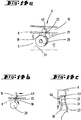
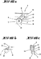
- the Figures 13a , 14a , 15a , 16a and 17a show the engagement element 22 of the locking device 9 in different locking positions.
- Figures 13b, 14b, 15b, 16b and 17b represent the operating principle of the respective position
- Figures 13c , 14c , 15c , 16c and 17c show the locking device 9 in a cross section.
- the Figures 13a, 13b and 13c first show an initial position of the engagement element 22, in which the end-side partial area 43 of the engagement element 22 does not yet reach behind the collar 46 of the cover 8.
- the sub-area 43 slides when the locking element 10 is rotated to the right in the figures (see for example Figure 13b ) along a ramp 18 of the locking element 10 and is as in the Figures 14a and 14b shown pivoted to the right.
- the engagement element 22 initially slides along the guide track 21 of the guide slot 20, as in particular in FIG Figure 14c recognizable, outwards, ie away from the pot 5, until the hook-shaped portion 43 of the engagement element 22 engages behind the collar 46 of the lid 8 and clamps it in a radially outward direction (viewed from an interior of the pot 5).
- the engagement element 22 tilts, as in FIG Figures 15a, 15b and 15c shown, further to the right, the ramp 18 of the locking element 10 following.
- the engagement element 22 is thereby displaced further along the guide track 21 of the guide slot 20 and into the in Figure 15c Move the illustrated end position in which the cover 8 is completely pulled down onto the pot 5 and also braced in the radial direction.
- the lid 8 can be released from the pot 5 again by actuating the locking device 9 in the opposite direction, ie the locking element 10 is now rotated to the left in relation to the illustration of the figures.
- the following positions of the engagement element 22 are shown in FIGS. 16 and 17. Even during the release movement for unlocking the cover 8, the engagement element 22 follows the guide contour 51 of the locking element 10.
- FIGS. 18a and 18b show a particular embodiment of a food processor 4 according to the invention, on the receiving area 2 of which, here for example a coupling element 31, two radially outwardly pointing wing-like securing elements 25 are arranged, which engage behind corresponding undercuts 26 of the pot base 6 of the preparation vessel 1.
- the safety device 24 locks the preparation vessel 1 with the base device 3 of the food processor 4 when the coupling element 31 of the actuation device 12 is in a rotational position corresponding to a locked position of the lid 8 on the pot 5.
- Both the locking device 9 for the lid 8 and the safety device 24 for locking the preparation vessel 1 on the base unit 3 are operated via the same actuating device 12 of the kitchen appliance 4, so that only a single electric motor 40 is required to perform several locking functions.
Landscapes
- Engineering & Computer Science (AREA)
- Food Science & Technology (AREA)
- Mechanical Engineering (AREA)
- Cookers (AREA)
- Food-Manufacturing Devices (AREA)
Abstract
Description
- Die Erfindung betrifft ein Zubereitungsgefäß zum Verbinden mit einem Aufnahmebereich eines Basisgerätes einer elektromotorisch betriebenen Küchenmaschine, wobei das Zubereitungsgefäß einen Topf, einen mit dem Aufnahmebereich verbindbaren Topffuß und einen eine Topföffnung des Topfes verschließenden Deckel aufweist.
- Des Weiteren betrifft die Erfindung eine elektromotorisch betriebene Küchenmaschine, insbesondere ein Mixgerät, mit einem Basisgerät und einem mit einem Aufnahmebereich des Basisgerätes verbindbaren Zubereitungsgefäß, welches einen Topf und einen eine Topföffnung verschließenden Deckel aufweist.
- Zubereitungsgefäße und Küchenmaschinen mit einem Zubereitungsgefäß sind im Stand der Technik bekannt. Das Gehäuse der Küchenmaschine kann beispielsweise einen Gefäßaufnahmebereich aufweisen, in welchen das Zubereitungsgefäß einsetzbar ist, wobei der Gefäßaufnahmebereich vorzugsweise zumindest bezogen auf einen Teilbereich formkorrespondierend zu dem Zubereitungsgefäß so ausgebildet ist, dass das Zubereitungsgefäß im Zuge des Verbindens mit dem Gefäßaufnahmebereich sowohl in Bezug auf eine vertikale Richtung, als auch in Bezug auf eine Umfangsrichtung des Zubereitungsgefäßes ausgerichtet werden kann.
- In dem Aufnahmebereich kann des Weiteren beispielsweise eine Rotationswelle angeordnet sein, welche zum Antrieb eines sich in dem Zubereitungsgefäß befindenden Rührwerkes dient. Das Rührwerk wird zur Zubereitung von Speisen über einen küchenmaschinenseitigen Elektromotor angetrieben. Um bei einem Betrieb der Küchenmaschine, insbesondere des Rührwerks, ein Herausspritzen von Lebensmitteln aus dem Zubereitungsgefäß zu vermeiden, weist das Zubereitungsgefäß einen Deckel auf, welcher mittels einer Verriegelungseinrichtung auf dem Topf verriegelbar ist.
- Eine im Stand der Technik bekannte Küchenmaschine mit einer Verriegelungseinrichtung für den Deckel des Zubereitungsgefäßes zeigt beispielsweise die Patentschrift
EP 2 813 165 B1 . Die Verriegelungseinrichtung weist zwei einen Topfrand sowie Deckelrand übergreifende Verriegelungsteile auf, die als um eine im Wesentlichen horizontale Achse rotierende Verriegelungswalzen ausgebildet sind. Die Verriegelungswalzen können von einer Freigabestellung in eine Verriegelungsstellung und umgekehrt rotiert werden. - Obwohl sich die vorgenannte Verriegelungseinrichtung zur sicheren Verriegelung des Deckels auf dem Topf bewährt hat, ist diese Ausbildung daran gebunden, dass mit einem bestimmten Basisgerät der Küchenmaschine auch ein bestimmtes, insbesondere mit der Höhe der Verriegelungswalzen übereinstimmendes, Zubereitungsgefäß verwendet wird. Dadurch ist es gegebenenfalls nicht möglich, verschiedene Zubereitungsgefäße in Verbindung mit der Küchenmaschine zu benutzen, insbesondere Zubereitungsgefäße mit zueinander verschiedenen Höhen.
- Ausgehend von dem vorgenannten Stand der Technik ist es daher Aufgabe der Erfindung, ein Zubereitungsgefäß für eine Küchenmaschine zu schaffen, welches einerseits eine Verriegelung des Deckels mit dem Topf ermöglicht, und andererseits unabhängig von einer Aufbauhöhe des Zubereitungsgefäßes mit einem Basisgerät der Küchenmaschine verbindbar ist.
- Zur Lösung der vorgenannten Aufgabe wird vorgeschlagen, dass das Zubereitungsgefäß eine Verriegelungseinrichtung mit einem Verriegelungselement zum Verriegeln des Topfes mit dem Deckel aufweist, wobei der Topffuß mindestens ein Betätigungselement zur Betätigung der Verriegelungseinrichtung aufweist, wobei das Betätigungselement so an dem Topffuß angeordnet ist, dass dieses von einer korrespondierenden Betätigungseinrichtung des Aufnahmebereiches der Küchenmaschine betätigbar ist.
- Erfindungsgemäß befindet sich die Verriegelungseinrichtung, die dem Verriegeln des Deckels mit dem Topf dient, an dem Zubereitungsgefäß selbst. Damit erübrigt sich eine an der Küchenmaschine ausgebildete Verriegelungseinrichtung, welche zur ordnungsgemäßen Verriegelungsfunktion eine bestimmte Geometrie, insbesondere Höhe, des Zubereitungsgefäßes voraussetzen würde. Das erfindungsgemäße Zubereitungsgefäß ist durch das an dem Topffuß bereitgestellte Betätigungselement so ausgebildet, dass die Verriegelungseinrichtung des Zubereitungsgefäßes mittels einer Betätigungseinrichtung der das Zubereitungsgefäß aufnehmenden Küchenmaschine betätigt werden kann. Vorzugsweise befindet sich das Betätigungselement unterseitig an dem Zubereitungsgefäß, so dass dieses bei Verbinden des Zubereitungsgefäßes mit dem Aufnahmebereich des Basisgerätes in Kontakt mit einem Element der küchenmaschinenseitigen Betätigungseinrichtung kommt. Gemäß einer Ausbildung kann die Verriegelungseinrichtung als Verriegelungselement beispielsweise korrespondierend an dem Topf und dem Deckel ausgebildete Bajonettverschlusselemente aufweisen und an einem der Bajonettverschlusselemente z. B. eine Verzahnung bereitstellen, in welche ein Teilbereich eines Antriebselementes eingreift, um die beiden Bajonettverschlusselemente relativ zueinander zu rotieren. Der Bajonettverschluss kann dabei, insbesondere durch beispielsweise eine rampenförmige Ausbildung eines der korrespondierenden Bajonettverschlusselemente, eine axiale Verlagerung des Deckels in Richtung des Topfes bewirken, so dass der Deckel auf den Rand der Topföffnung gedrückt wird und somit ein festes und insbesondere fluiddichtes Verschließen des Zubereitungsgefäßes erfolgt. Die vorgeschlagene Ausführung ist nur eine mögliche einer Vielzahl von denkbaren Ausführungsformen der Erfindung, welche im Einzelnen noch näher beschrieben werden. Wesentlich ist im Sinne der Erfindung jedenfalls, dass die Verriegelungseinrichtung zum Verriegeln des Deckels mit dem Topf ausschließlich dem Zubereitungsgefäß zugehörig ist und lediglich an dem Topffuß des Zubereitungsgefäßes eine Schnittstelle angeordnet ist, die eine Betätigung der Verriegelungseinrichtung des Zubereitungsgefäßes durch eine Betätigungseinrichtung eines Basisgerätes einer Küchenmaschine erlaubt. Die Schnittstelle befindet sich vorzugsweise unter dem Zubereitungsgefäß, d. h. im Bereich einer im Wesentlichen horizontalen Kontaktfläche zwischen dem Aufnahmebereich des Basisgerätes und dem Topffuß des Topfes des Zubereitungsgefäßes, so dass das Zubereitungsgefäß sehr unterschiedlich geformt sein kann, insbesondere in Bezug auf dessen Höhe und/oder Durchmesser. Eine Kompatibilität zwischen verschiedenen Zubereitungsgefäßen und verschiedenen Basisgeräten einer Küchenmaschine wird somit erleichtert.
- Es wird vorgeschlagen, dass die Verriegelungseinrichtung eine das Verriegelungselement antreibende und mit dem Betätigungselement in mechanischer Wirkverbindung stehende Antriebseinrichtung aufweist. Die Antriebseinrichtung des Zubereitungsgefäßes dient zur Übertragung mechanischer Kräfte von einer Betätigungseinrichtung einer Küchenmaschine auf das Verriegelungselement der Verriegelungseinrichtung des Zubereitungsgefäßes. Die Betätigungseinrichtung der Küchenmaschine kann beispielsweise einen Elektromotor aufweisen, welcher direkt das Betätigungselement des Zubereitungsgefäßes antreibt oder vorzugsweise unter Zwischenanordnung eines Getriebes auf das Betätigungselement wirkt. Das Getriebe der Küchenmaschine kann beispielsweise eine Mehrzahl von Verzahnungselementen aufweisen, beispielsweise ein Stirnradgetriebe und ein Schneckengetriebe, und mit einem in der Wirkungskette zuletzt angetriebenen Getriebeelement auf das Betätigungselement des Zubereitungsgefäßes einwirken. Das Betätigungselement des Zubereitungsgefäßes, beispielsweise ein in dem Topffuß des Zubereitungsgefäßes angeordnetes Zahnrad, ist Teil der gefäßseitigen Antriebseinrichtung, die in mechanischer Wirkverbindung mit der Betätigungseinrichtung der Küchenmaschine steht. Das Betätigungselement des Zubereitungsgefäßes überträgt die Antriebskraft schließlich via der Antriebseinrichtung auf das Verriegelungselement, welches das Verriegeln des Deckels auf dem Topf bewirkt.
- Die Antriebseinrichtung kann gemäß einer bevorzugten Ausgestaltung ein Antriebselement aufweisen, welches ausgehend von dem Topffuß bis zu dem Deckel durch eine Wandung des Topfes und/oder einen Handgriff des Topfes geführt ist. Bei dem Antriebselement kann es sich insbesondere um eine Rotationswelle handeln. Gemäß dieser Ausgestaltung kann die Verriegelungseinrichtung aus besonders wenigen Einzelteilen hergestellt sein. Insbesondere kann das Betätigungselement der Verriegelungseinrichtung in dem Topffuß unmittelbar mit dem Antriebselement verbunden sein, welches im Bereich der Gefäßöffnung dann auf das Verriegelungselement wirkt, um schlussendlich die Verriegelung des Deckels mit dem Topf herbeizuführen. Eine Rotationswelle eignet sich als Antriebselement insbesondere, da diese platzsparend in eine Wandung des Topfes und/oder einen Handgriff des Topfes integriert werden kann. Dadurch ergibt sich eine Ausgestaltung, bei welcher alle Elemente der Antriebseinrichtung in das Gehäuse des Zubereitungsgefäßes integriert sind und nicht nach außen ragen, wo sich ein Nutzer des Zubereitungsgefäßes verletzen könnte oder sich Lebensmittelreste oder Schmutz ablagern können. Somit wird nicht zuletzt auch die Reinigung des Zubereitungsgefäßes erleichtert. In der Wandung des Topfes bzw. in dem Handgriff kann ein Hohlraum vorgesehen sein, innerhalb dessen sich das Antriebselement, bevorzugt eine Rotationswelle, erstreckt. Das Antriebselement, bevorzugt die Rotationswelle, kann im Bereich der Topföffnung auf das Verriegelungselement der Verriegelungseinrichtung einwirken. Beispielsweise kann ein Teilbereich des Antriebselementes eine Verzahnung aufweisen, die in eine entsprechende Verzahnung des Verriegelungselementes eingreift.
- Gemäß einer besonderen Ausführung kann das Verriegelungselement ein rotierbar an dem Topf oder dem Deckel gelagerter, die Topföffnung in einem mittels des Deckels verschlossenen Zustand umgebender Verriegelungsring sein, wobei dem Verriegelungselement eine Antriebseinrichtung zugeordnet ist, welche eingerichtet ist, das Verriegelungselement um die Topföffnung zu rotieren. Der Verriegelungsring kann seinerseits beispielsweise unmittelbar eine Verriegelung zwischen dem Topf und dem Deckel herbeiführen oder zunächst auf ein Zwischenelement einwirken, welches dann die Verriegelung herbeiführt. Der Verriegelungsring kann beispielsweise ein Element eines Bajonettverschlusses bereitstellen und/oder eine Kulisse mit Rampen oder ähnlichem bereitstellen, welche eine insbesondere axiale Verlagerung des Deckels relativ zu dem Topf ermöglichen. Dadurch kann der Deckel auf den Topf gedrückt oder gezogen werden und insbesondere so verspannt werden, dass eine fluiddichte Verriegelung des Topfes gewährleistet ist. Gemäß dieser Ausgestaltung ist das Verriegelungselement nicht bewegungsfest mit dem Topf bzw. dem Deckel verbunden, sondern vielmehr relativ zu diesem rotierbar. Dadurch muss lediglich das Verriegelungselement von der Antriebseinrichtung rotiert werden, und nicht etwa der ganze Deckel. Dadurch ist es möglich, für die Antriebseinrichtung des Zubereitungsgefäßes sowie auch die Betätigungseinrichtung der Küchenmaschine leichtere und/oder kleinere Komponenten bzw. einen Elektromotor mit geringerer Leistung zu verwenden, was bei der Herstellung des Zubereitungsgefäßes und/oder der Küchenmaschine Gewicht und Kosten spart.
- Es wird vorgeschlagen, dass das Verriegelungselement zumindest ein Wirkelement aufweist, welches ausgebildet ist, bei Rotation des Verriegelungselementes eine axiale Verlagerung des Deckels zu dem Topf (5) hin und/oder ein radial nach außen wirkendes Verspannen des Deckels zu bewirken. Ein solches Wirkelement kann beispielsweise eine Rampe sein, welche in Verriegelungsrichtung an dem als Verriegelungsring ausgebildeten Verriegelungselement ausgebildet ist. In diesem Fall weist das Verriegelungselement eine Führungskulisse auf, an welcher ein korrespondierender Teilbereich des Deckels oder des Topfes entlanggleiten kann. Des Weiteren kann ein Wirkelement beispielsweise auch ein Teilelement eines Bajonettverschlusses sein, wobei ein Teilbereich des Verriegelungselementes in eine korrespondierende Öffnung des Deckels bzw. des Topfes hineingreift. In jedem Fall ist das Wirkelement so ausgebildet, dass es bei Rotation des Verriegelungselementes zu einer axialen Verlagerung des Deckels relativ zu dem Topf und/oder zu einem Verspannen des Deckels in eine radial nach außen weisende Richtung kommt. Das Wirkelement des Verriegelungselementes kontaktiert den betreffenden Teilbereich des Deckels bzw. Topfes und drängt den Deckel in die gewünschte Verriegelungsposition. Insofern bildet das Wirkelement ein Führungselement einer Führungseinrichtung bzw. Führungskulisse. Beispielsweise kann das Verriegelungselement auch ein elastischer Verriegelungsring sein, welcher rotierbar an dem Topf gelagert ist und sich bei Rotation entlang einer Kulisse des Topfes aufweitet und zusätzlich axial in Längserstreckung des Topfes verlagert wird. Beim Aufweiten taucht der Verriegelungsring beispielsweise in einen Hinterschnitt des Deckels ein und bewegt diesen in eine Verriegelungsstellung. Die radiale und axiale Verlagerungsbewegung erfolgen dabei vorzugsweise nacheinander, wobei zuerst eine Bewegung nach außen, und dann in Längsrichtung des Topfes bevorzugt ist. Alternativ zu einer elastischen Ausbildung des Verriegelungsringes kann der Verriegelungsring auch auf einem Grundkörper beweglich gelagerte Teilelemente aufweisen, die bei Rotation nach radial außen verlagert werden können. Darüber hinaus kann der Verriegelungsring auch bezogen auf einen oder mehrere Umfangsteilbereiche geschlitzt sein, so dass ein korrespondierendes Kulissenelement zumindest zeitweise in den Verriegelungsring eingreifen kann und dadurch eine Durchmesseränderung des Verriegelungsringes hervorruft.
- Gemäß einer möglichen Ausführung wird vorgeschlagen, dass das Wirkelement zur Bildung eines Bajonettverschlusses in eine korrespondierende Öffnung des Deckels oder des Topfes eingreifbar ist, wobei das Wirkelement oder ein Teilbereich des Deckels oder des Topfes eine in Verriegelungsrotationsrichtung ansteigende Rampe aufweist, die eine axiale Verlagerung des Deckels relativ zu dem Topf und damit ein Verriegeln des Topfes mit dem Deckel bewirkt. Gemäß dieser Ausgestaltung bildet das Wirkelement ein Teilelement eines Bajonettverschlusses. Das korrespondierende Element des Bajonettverschlusses ist dabei ein Teilbereich des Deckels bzw. des Topfes mit einer Öffnung. Das Wirkelement greift in die Öffnung hinein und folgt bei der Rotation des Verriegelungselementes einer ansteigenden Rampe, woraus eine axiale Verlagerung des Deckels relativ zu dem Topf resultiert. Die Rampe kann an dem Wirkelement selbst ausgebildet sein, wobei ein Teilbereich des Wirkelementes durch die Öffnung des Deckels bzw. des Topfes im Sinne eines Bajonettverschlusses hindurchgreift und ein anderer Teilbereich des Wirkelementes die Rampe aufweist bzw. an einer korrespondierenden Rampe des Deckels bzw. des Topfes entlanggleitet. Das Wirkelement und die Rampe können auch örtlich voneinander getrennt ausgebildet sein, wobei das Wirkelement nur die Funktion hat, in die Öffnungen des Bajonettverschlusses einzugreifen, und die Rampe dafür sorgt, dass der Deckel relativ zu dem Topf verspannt wird. In diesem Sinne sind zwei gleichwirkende Ausführungsformen möglich. Bei einer ersten Ausführungsform kann der rotierende Verriegelungsring an dem Topf des Zubereitungsgefäßes gelagert sein und in korrespondierende Bajonettkonturen des Deckels eingreifen und den Deckel dadurch in Richtung des Topfes ziehen. Gemäß einer alternativen Ausführungsform kann das rotierende Verriegelungselement ein an dem Deckel gelagerter Verriegelungsring sein, welcher in korrespondierende Bajonettkonturen des Topfes eingreift und den Deckel somit in Richtung des Topfes verlagert. Die korrekte Funktion des Bajonettverschlusses ist von einem gerichteten Auflegen des Deckels auf den Topf abhängig, so dass korrespondierende Elemente des Bajonettverschlusses ineinandergreifen können. Um darüber hinaus zu verhindern, dass sich der Deckel bei Betätigung des Verriegelungsringes mitbewegt, weisen der Topf und/oder der Deckel vorzugsweise Anschlagselemente auf, die als Verdrehsicherung dienen. Um darüber hinaus erkennen zu können, ob der Deckel richtig mit dem Topf verriegelt ist, können die korrespondierenden Bajonettelemente des Bajonettverschlusses mit Endanschlägen ausgestattet sein. Wenn der Deckel zu Beginn der Verriegelungsbewegung richtig auf den Topf aufgelegt ist, ist es möglich, den Verriegelungsring zu rotieren, bis ein Endanschlag an dem korrespondierenden Bajonettelement erreicht ist. Wenn der Deckel nicht korrekt, beispielsweise schräg, aufgelegt ist, ist es nicht möglich, den Verriegelungsring bis zu dem Endanschlag zu rotieren. Wenn gar kein Deckel auf den Topf aufgelegt ist, kann der Verriegelungsring über ein definiertes Maß hinaus rotiert werden, da der Verriegelungsring nicht gegen ein Anschlagselement stößt. Durch eine Auswertung einer aktuellen Rotationsstellung des Verriegelungsringes kann somit ermittelt werden, ob ein Deckel auf den Topf aufgelegt ist bzw. ob der Deckel korrekt mit dem Topf verriegelt ist.
- Eine alternative Ausführungsform der Erfindung kann vorsehen, dass der Topf oder der Deckel ein beweglich an dem Topf bzw. dem Deckel gelagertes Zwischenelement aufweist, wobei das Wirkelement des Verriegelungselementes ausgebildet ist, das Zwischenelement bei Rotation des Verriegelungselementes in axialer und/oder radialer Richtung gegen einen Teilbereich des Deckels bzw. des Topfes zu drücken und dadurch ein Verriegeln des Topfes mit dem Deckel zu bewirken. Gemäß dieser Ausgestaltung wird der Deckel nicht unmittelbar mittels des Verriegelungselementes mit dem Topf verriegelt. Vielmehr wirkt das Wirkelement des Verriegelungselementes zunächst auf ein Zwischenelement, welches dann die Verriegelung zwischen dem Deckel und dem Topf hervorruft. Dadurch kann die Verriegelung unabhängig von einer Rotationsstellung des Deckels auf dem Topf zuverlässig erreicht werden. Der Komfort für den Nutzer ist erhöht, da diese Ausführungsform ein zuverlässiges Verriegeln auch bei ungerichtetem Auflegen des Deckels auf den Topf erlaubt. Das Zwischenelement kann in axialer und/oder radialer Richtung beweglich an dem Topf bzw. Deckel gelagert sein, wobei der auf dem Topf aufgelegte Deckel zunächst das Zwischenelement so in radialer und/oder axialer Richtung wegdrückt, dass dieses wiederum auf einen korrespondierenden Teilbereich des Deckels bzw. des Topfes wirkt und somit eine Verriegelung zwischen Topf und Deckel herbeiführt. Vorzugsweise kann das Verriegelungselement in Umfangsrichtung mehrere Kulissenelemente aufweisen, die im Sinne einer Kulissenführung auf ein oder mehrere Zwischenelemente wirken. Insbesondere kann es vorgesehen sein, dass das Wirkelement des Verriegelungselementes eine Führungskulisse bereitstellt, die bei Kontakt mit dem Zwischenelement und fortgeführter Rotation des Verriegelungselementes in Verriegelungsrichtung eine Verlagerung des Zwischenelementes sowohl in radiale Richtung, als auch in axiale Richtung bewirkt. Beispielsweise kann das Zwischenelement zunächst in eine bezogen auf das Topfinnere nach außen weisende radiale Richtung verlagert werden, wobei das Zwischenelement hinter einen an dem Deckel ausgebildeten Hinterschnitt greift. Bei weitergeführter Rotation des Verriegelungselementes wird das Zwischenelement dann durch eine entsprechende Formgestaltung des Wirkelementes in Längsrichtung des Topfes verlagert. Dabei nimmt das Zwischenelement den Deckel mit, bis dieser eine Endlage erreicht. Um den Deckel wieder zu entriegeln, kann der Verriegelungsring beispielsweise in entgegengesetzte Richtung rotiert werden, wobei das Zwischenelement mittels einer Rückstellfeder wieder aus der Endlage herausverlagert wird, d. h. sich in Richtung des Verriegelungselementes bewegt und der Deckel gelöst werden kann. Alternativ ist die Rückwärtsbewegung des Zwischenelementes auch mittels einer Kulissenführung möglich, oder mittels einer Kombination aus einer Rückstellfeder und einer Kulissenführung. Das Zwischenelement kann insbesondere in axiale und/oder radiale Richtung schwenkbar an dem Topf oder dem Deckel gelagert sein. Alternativ ist es möglich, dass das Zwischenelement ein zu dem Verriegelungsring zweiter Rotationsring ist, der mittels des Verriegelungsringes manipuliert werden kann, beispielsweise so, dass sich das ringförmige Zwischenelement bei Kontakt mit dem Verriegelungsring und Rotation in Verriegelungsrichtung zunächst aufweitet und dann in axiale Richtung verlagert wird, so dass der Zwischenring beim Aufweiten beispielsweise in einen Hinterschnitt des Deckels bzw. des Topfes eingreift und den Deckel anschließend in axiale Richtung in eine Verriegelungsposition verlagert. Um zu erkennen, ob sich der Deckel tatsächlich auf dem Topf befindet und korrekt verriegelt wurde, kann ein Detektionsmechanismus zum Einsatz kommen. Der Detektionsmechanismus kann beispielsweise einen Detektionshebel beinhalten, der mit dem Verriegelungsring zusammenwirkt. Der Detektionshebel kann von einer Feder gegen den Verriegelungsring gedrückt werden. Der Verriegelungsring weist eine Aussparung auf. Wenn sich der Deckel nicht in einer zum Verriegeln geeigneten Position befindet, drückt die Feder den Detektionshebel in die Aussparung des Verriegelungsringes hinein, so dass der Verriegelungsring blockiert wird und nicht rotiert werden kann. Sofern der Deckel korrekt verriegelt wurde, wird der Detektionshebel von einem Rand des Deckels nach unten gedrückt, so dass der Detektionshebel nicht in die Aussparung des Verriegelungsringes eingreifen kann. Der Verriegelungsring kann dann ungehindert weiterrotieren. Zur Detektion der damit erreichten Rotationsstellung kann beispielsweise ein Rotationswinkel des Verriegelungsrings erfasst und ausgewertet werden, beispielsweise durch Ermitteln einer Anzahl von Umdrehungen einer Rotationswelle eines Antriebsmotors der Betätigungseinrichtung der Küchenmaschine. Ein blockierter Verriegelungsring kann des Weiteren zum Beispiel durch Auswerten eines Motorstroms erkannt werden. In dem Fall, dass der Deckel nicht korrekt auf den Topf aufgesetzt ist, wird der Verriegelungsring blockiert bevor eine definierte Rotationsstellung erreicht ist. Dieser Zustand wird als fehlerhafter Verriegelungszustand interpretiert. Bei korrekt aufgesetztem Deckel kann der Verriegelungsring hingegen weiterrotieren bis die definierte Rotationsstellung überschritten ist. Dieser Zustand wird dann als korrekt verriegelter Deckel interpretiert. Durch Anordnung mehrerer Detektionshebel und Aussparungen am Umfang des Verriegelungsrings kann besonders vorteilhaft ein Erreichen einer Verriegelungsstellung an mehreren Umfangspositionen des Deckels erkannt werden. Auf diese Weise kann sichergestellt werden, dass zum Beispiel auch ein schräg auf den Topf aufgelegter Deckel als Fehlerzustand erkannt wird.
- Gemäß einer weiteren möglichen Ausführung kann das Zubereitungsgefäß eine an dem Topf angeordnete Führungskulisse mit einem in einer spiralförmigen Führungsbahn der Führungskulisse gelagerten Eingriffselement aufweisen, wobei die Führungsbahn um eine bezogen auf ein Inneres des Topfes nach radial außen weisende Spiralachse verläuft, und wobei eine Rotation des Verriegelungselementes eine axiale und radiale Verlagerung des Eingriffselementes entlang der spiralförmigen Führungsbahn zu einem Teilbereich des Deckels hin bewirkt bis ein aus der Führungskulisse herausweisender Teilbereich des Eingriffselementes an dem Deckel anliegt und damit ein Verriegeln des Topfes mit dem Deckel bewirkt ist. Auch bei dieser Ausgestaltung kann der Deckel in beliebiger Rotationsposition auf den Topf aufgelegt werden. Die Führungskulisse zur Bewirkung der Verriegelung ist dabei jedoch nicht dem Verriegelungsring zugeordnet, sondern an dem Topf angeordnet. In der Führungskulisse ist ein Eingriffselement geführt, welches durch den rotierenden Verriegelungsring manipuliert wird, nämlich derart, dass das Eingriffselement durch die Führungsbahn gezwungen wird und dabei gleichzeitig sowohl in eine radiale Richtung, als auch in eine axiale Richtung des Topfes verlagert wird. Das verlagerte Eingriffselement wirkt entlang seiner Verlagerungsbahn auf einen korrespondierenden Teilbereich des Deckels ein und verriegelt dadurch den Deckel mit dem Topf, indem der Deckel in axiale Richtung auf den Topf zu verlagert und mit diesem verspannt wird.
- Neben dem zuvor beschriebenen Zubereitungsgefäß wird mit der Erfindung des Weiteren eine elektromotorisch betriebene Küchenmaschine, insbesondere ein Mixgerät, vorgeschlagen, wobei die Küchenmaschine ein Basisgerät und ein mit einem Aufnahmebereich des Basisgerätes verbindbares Zubereitungsgefäß aufweist, welches einen Topf und einen eine Topföffnung verschließenden Deckel aufweist, wobei das Zubereitungsgefäß des Weiteren nach einer der zuvor beschriebenen Ausführungsformen ausgebildet ist und das Basisgerät eine Betätigungseinrichtung aufweist, welche eingerichtet ist, die Verriegelungseinrichtung des Zubereitungsgefäßes im miteinander verbundenen Zustand von Basisgerät und Zubereitungsgefäß zu betätigen. Die Merkmale und Vorteile des Zubereitungsgefäßes ergeben sich somit entsprechend auch für die elektromotorisch betriebene Küchenmaschine. Insgesamt wird somit eine Küchenmaschine geschaffen, die mit einer Vielzahl von unterschiedlich ausgebildeten Zubereitungsgefäßen betrieben werden kann. Insbesondere ist die ordnungsgemäße Funktion der Küchenmaschine nicht mehr von einem Zubereitungsgefäß bestimmter Höhe abhängig. Vielmehr stellt das erfindungsgemäße Zubereitungsgefäß nun eine eigene Verriegelungseinrichtung bereit, so dass das Basisgerät der Küchenmaschine keine Verriegelungseinrichtung für das Zubereitungsgefäß mehr aufweisen muss. Der Topf des Zubereitungsgefäßes kann eine Vielzahl unterschiedlicher Höhen aufweisen und kann trotzdem noch so mit dem Basisgerät verbunden werden, dass der Deckel optimal mit dem Topf verriegelt werden kann. Der Topf ist in jedem Fall so ausgebildet, dass dessen Topffuß ein Betätigungselement zur Betätigung der Verriegelungseinrichtung des Zubereitungsgefäßes aufweist, wobei eine in dem Basisgerät angeordnete Betätigungseinrichtung zu dem Betätigungselement korrespondiert und dieses betätigen kann. Das Basisgerät weist als Betätigungseinrichtung vorzugsweise einen Elektromotor mit einem zugeordneten Getriebe auf, welches auf das Betätigungselement der Verriegelungseinrichtung einwirkt und somit ein Verriegeln des Deckels mit dem Topf veranlasst.
- Es wird des Weiteren vorgeschlagen, dass die Küchenmaschine eine Sicherungseinrichtung zur Verriegelung des Zubereitungsgefäßes an dem Basisgerät der Küchenmaschine aufweist, wobei die Sicherungseinrichtung ein an dem Zubereitungsgefäß beweglich gelagertes Sicherungselement aufweist, welches hinter einen Hinterschnitt des Basisgerätes bewegbar ist, oder wobei die Sicherungseinrichtung ein an dem Basisgerät beweglich gelagertes Sicherungselement aufweist, welches hinter einen Hinterschnitt des Zubereitungsgefäßes bewegbar ist, wobei die Betätigungseinrichtung des Basisgerätes ausgebildet ist, gleichzeitig und zusätzlich zu der Betätigung der Verriegelungseinrichtung auch das Sicherungselement der Sicherungseinrichtung anzutreiben. Der Betätigungsmechanismus für die Deckelverriegelung kann somit gleichzeitig auch zur Verriegelung des Zubereitungsgefäßes an dem Basisgerät genutzt werden. Hierzu kann beispielsweise an dem Getriebe der Betätigungseinrichtung des Basisgerätes ein Vorsprung oder ein Hinterschnitt angeordnet sein, der bei einem bestimmten Rotationswinkel eines Getriebeelementes in eine an dem Topf angebrachte Gegenkontur greift. Je nach dem Rotationswinkel des Getriebeelementes kann der Topf dann entweder von dem Basisgerät getrennt werden oder fest mit diesem verbunden bleiben. Alternativ kann ein Vorsprung bzw. ein Hinterschnitt auch an einem Teilbereich des Zubereitungsgefäßes angeordnet sein, beispielsweise an einem beweglichen Element der Antriebseinrichtung des Zubereitungsgefäßes.
- Im Folgenden wird die Erfindung anhand von Ausführungsbeispielen näher erläutert. Es zeigen:
- Fig. 1
- eine Küchenmaschine mit einem Zubereitungsgefäß,
- Fig. 2
- einen Aufnahmebereich der Küchenmaschine mit einem Zubereitungsgefäß in einer Ansicht von unten,
- Fig. 3
- ein Zubereitungsgefäß gemäß einer ersten Ausführungsform in einer Schnittansicht,
- Fig. 4
- eine Draufsicht auf das Zubereitungsgefäß,
- Fig. 5
- eine Topföffnung des Zubereitungsgefäßes mit einem Verriegelungselement,
- Fig. 6
- einen Teilbereich eines Deckels des Zubereitungsgefäßes und ein Verriegelungselement in einer ersten Stellung,
- Fig. 7
- den Teilbereich des Deckels des Zubereitungsgefäßes und das Verriegelungselement in einer zweiten Stellung,
- Fig. 8
- den Teilbereich des Deckels des Zubereitungsgefäßes und das Verriegelungselement in einer dritten Stellung,
- Fig. 9a
- eine Verriegelungseinrichtung gemäß einer zweiten Ausführungsform in einer ersten Stellung,
- Fig. 9b
- eine Seitenansicht gemäß
Fig. 9a , - Fig. 10a
- die Verriegelungseinrichtung gemäß
Fig. 9a in einer zweiten Stellung, - Fig. 10b
- eine Seitenansicht gemäß
Fig. 10a , - Fig. 11a
- die Verriegelungseinrichtung gemäß
Fig. 9a und Fig. 10a in einer dritten Stellung, - Fig. 11b
- eine Seitenansicht gemäß
Fig. 11a , - Fig. 12a
- eine perspektivische Ansicht der in
Fig. 11a und Fig. 11b dargestellten Stellung von schräg unten betrachtet, - Fig. 12b
- eine Stellung einer Detektionseinrichtung bei ordnungsgemäß mit dem Topf verbundenem Deckel,
- Fig. 12c
- eine Stellung der Detektionseinrichtung bei Abwesenheit des Deckels,
- Fig. 13a
- eine Verriegelungseinrichtung gemäß einer weiteren Ausführungsform in einer ersten Stellung,
- Fig. 13b
- die Verriegelungseinrichtung gemäß
Fig. 13a als skizziertes Wirkprinzip, - Fig. 13c
- die Darstellung gemäß
Fig. 13b in einer Seitenansicht, - Fig. 14a
- eine Verriegelungseinrichtung gemäß einer weiteren Ausführungsform in einer ersten Stellung,
- Fig. 14b
- die Verriegelungseinrichtung gemäß
Fig. 14a als skizziertes Wirkprinzip, - Fig. 14c
- die Darstellung gemäß
Fig. 14b in einer Seitenansicht, - Fig. 15a
- eine Verriegelungseinrichtung gemäß einer weiteren Ausführungsform in einer ersten Stellung,
- Fig. 15b
- die Verriegelungseinrichtung gemäß
Fig. 15a als skizziertes Wirkprinzip, - Fig. 15c
- die Darstellung gemäß
Fig. 15b in einer Seitenansicht, - Fig. 16a
- eine Verriegelungseinrichtung gemäß einer weiteren Ausführungsform in einer ersten Stellung,
- Fig. 16b
- die Verriegelungseinrichtung gemäß
Fig. 16a als skizziertes Wirkprinzip, - Fig. 16c
- die Darstellung gemäß
Fig. 16b in einer Seitenansicht, - Fig. 17a
- eine Verriegelungseinrichtung gemäß einer weiteren Ausführungsform in einer ersten Stellung,
- Fig. 17b
- die Verriegelungseinrichtung gemäß
Fig. 17a als skizziertes Wirkprinzip, - Fig. 17c
- die Darstellung gemäß
Fig. 17b in einer Seitenansicht, - Fig. 18a, 18b
- ein Zubereitungsgefäß mit einer Sicherungseinrichtung zum Verriegeln des Zubereitungsgefäßes an einem Basisgerät einer Küchenmaschine.
-
Figur 1 zeigt eine Küchenmaschine 4 mit einem Basisgerät 3, welches einen Aufnahmebereich 2 zur Verbindung mit einem Zubereitungsgefäß 1 aufweist. Das Basisgerät 3 der Küchenmaschine 4 verfügt über ein Display 27 zum Anzeigen von Funktionen der Küchenmaschine 4 und gegebenenfalls Rezepten, welche mittels der Küchenmaschine 4 zubereitet werden können. Neben dem Display 27 befindet sich ein Schalter 28, welcher einerseits zum Ein- und Ausschalten der Küchenmaschine 4, und andererseits zum Bestätigen von Eingabebefehlen oder ähnlichem dient. Das Zubereitungsgefäß 1 weist einen Topf 5 mit einem Handgriff 16 und einem Topffuß 6 auf, welcher zur Verbindung mit dem Aufnahmebereich 2 der Küchenmaschine 4 dient, sowie einen Deckel 8 mit einer Deckelöffnung 29 und einem Deckelgriff 30. Durch die Deckelöffnung 29 hindurch können beispielsweise Zutaten in den Topf 5 des Zubereitungsgefäßes 1 eingegeben werden. - Die
Figuren 2 und3 zeigen im Einzelnen eine Verriegelungseinrichtung 9 des Zubereitungsgefäßes 1, mittels welcher der Topf 5 und der Deckel 8 des Zubereitungsgefäßes 1 miteinander verriegelt werden können. Der Aufnahmebereich 2 des Basisgerätes 3 der Küchenmaschine 4 verfügt über eine Betätigungseinrichtung 12 zur Einwirkung auf ein Betätigungselement 11 der Verriegelungseinrichtung 9 des Zubereitungsgefäßes 1, so dass die Küchenmaschine 4 einen Verriegelungsmechanismus des Zubereitungsgefäßes 1 betätigen kann, um den Deckel 8 mit dem Topf 5 zu verriegeln. Die Betätigungseinrichtung 12 der Küchenmaschine 4 weist hier beispielsweise im Einzelnen einen Elektromotor 40 auf, welcher ein Stirnradgetriebe 39 und ein damit verbundenes Schneckengetriebe 38 antreibt. Das Schneckengetriebe 38 wirkt wiederum auf ein Kupplungselement 31 des Basisgerätes 3. Das Kupplungselement 31 weist eine Verzahnung 36 auf, die in das Schneckengetriebe 38 eingreifen kann. Das Kupplungselement 31 dient zur Kupplung mit dem Betätigungselement 11 des - Zubereitungsgefäßes 1. Das Betätigungselement 11 der Verriegelungseinrichtung 9 wirkt wiederum auf eine Antriebseinrichtung 13, welche ein in Umfangsrichtung rotierbar an dem Topf 5 gelagertes Verriegelungselement 10 der Verriegelungseinrichtung 9 antreibt. Das Verriegelungselement 10 ist in axiale Richtung des Topfes 5 nicht verlagerbar. Die axiale Verlagerung verhindern hier beispielsweise ein an der Topföffnung 7 ausgebildeter Kragen 49 und der Handgriff 16 des Topfes 5. Die Antriebseinrichtung 13 verfügt über ein Antriebselement 14, welches hier beispielsweise in der Form einer Rotationswelle ausgebildet ist. Die Rotationswelle ist durch eine Wandung 15 des Handgriffs 16 des Zubereitungsgefäßes 1 geführt und reicht bis zur Höhe einer Topföffnung 7 des Topfes 5, an welcher sich das Verriegelungselement 10 der Verriegelungseinrichtung 9 befindet. Wie insbesondere in den
Figuren 4 und5 erkennbar ist das Verriegelungselement 10 als Bajonettring ausgebildet. Der Bajonettring weist zur Verriegelung des Deckels 8 mit dem Topf 5 Wirkelemente 17 auf, die in entsprechende Bajonettöffnungen 41 des Deckels 8 eingreifen können. Das Verriegelungselement 10 weist des Weiteren eine Verzahnung 37 auf, welche mit einer nicht weiter dargestellten Verzahnung des Antriebselementes 14 korrespondiert, so dass es bei einer Rotation des Antriebselementes 14 zu einer Rotation des Verriegelungselementes 10 um die Topföffnung 7 kommt. Um zu verhindern, dass sich bei Rotation des Verriegelungselementes 10 auch der Deckel 8 mitdreht, können an Topf 5 und Deckel 8 korrespondierende Anschlagselemente (nicht dargestellt) vorgesehen sein, beispielsweise im Bereich des Hangriffes 16 und des Deckelgriffes 30. - Die Erfindung gemäß dieser beispielhaften Ausführung einer Verriegelungseinrichtung 9 eines Zubereitungsgefäßes 1 funktioniert so, dass ein Nutzer das Zubereitungsgefäß 1 mit dem Basisgerät 3 der Küchenmaschine 4 verbindet. Dabei kommt es zu einer Kupplung zwischen dem Kupplungselement 31 des Aufnahmebereiches 2 der Küchenmaschine 4 und dem Betätigungselement 11 der Verriegelungseinrichtung 9 des Zubereitungsgefäßes 1. Wenn der Nutzer nun über beispielsweise das Display 27 oder den Schalter 28 der Küchenmaschine 4 eine Verriegelung des Topfes 5 mit dem Deckel 8 veranlasst, oder wenn eine solche Verriegelung automatisch durch eine Steuereinrichtung der Küchenmaschine 4 initiiert wird, treibt der der Verriegelungseinrichtung 9 zugeordnete Elektromotor 40 der Küchenmaschine 4 das Stirnradgetriebe 39, das Schneckengetriebe 38 und das Kupplungselement 31 der Küchenmaschine 4 an, so dass es zu einer Rotation des Betätigungselementes 11 und damit auch des Antriebselementes 14 der Antriebseinrichtung 13 für das Verriegelungselement 10 kommt. Bei dem Auflegen des Deckels 8 auf den Topf 5 hat der Nutzer bereits den Deckelgriff 30 mit dem Handgriff 16 in Übereinanderlage (siehe
Figur 1 ) gebracht. Dadurch werden die Wirkelemente 17 des Verriegelungselementes 10 in der Nähe der Bajonettöffnungen 41 des Deckels 8 positioniert. Die Antriebseinrichtung 13 des Zubereitungsgefäßes 1 rotiert nun das Verriegelungselement 10 und verlagert damit auch die Wirkelemente 17 relativ zu den Bajonettöffnungen 41 des Deckels 8, bis eine Endstellung und damit auch der Bajonettverschluss zwischen den korrespondieren Teilbereichen von Topf 5 und Deckel 8 erreicht ist. Vorzugsweise weisen die Wirkelemente 17 des Verriegelungselementes 10 (oder alternativ der Deckel 8) Rampen 18 auf, die ein axiales Heranziehen des Deckels 8 in Richtung der Topföffnung 7 bewirken und somit den Deckel 8 auf den Topf 5 drücken und diesen verriegeln. Obwohl dies in denFiguren 2 bis 5 nicht dargestellt ist, kann das Verriegelungselement 10, nämlich der Bajonettring, anstatt an dem Topf 5 auch an dem Deckel 8 angeordnet sein. - Die
Figuren 6 bis 8 zeigen eine Prinzipskizze des inFigur 4 dargestellten Bajonettverschlusses zwischen Topf 5 und Deckel 8, wobei der Deckel 8 Rampen 18 aufweist, an welchen das Wirkelement 17 des Verriegelungselementes 10 entlanggleiten kann.Figur 6 zeigt einen Teilbereich des Deckels 8 mit einer Bajonettöffnung 41, welche zum Aufnehmen des Wirkelementes 17 des Verriegelungselementes 10 dient. In dem inFigur 6 dargestellten Zustand befindet sich das Wirkelement 17 noch vollständig neben der Rampe 18 des Deckels 8. Der Deckel 8 ist jedoch in einer optimalen Ausgangsstellung auf den Topf 5 aufgelegt, so dass das Wirkelement 17 des Verriegelungselementes 10 so am Fuße der Rampe 8 positioniert ist, dass das Wirkelement 17 ausgehend davon bei Rotation des Verriegelungselementes 10 auf die Rampe 18 gleiten kann und schließlich wie inFigur 7 dargestellt durch die Bajonettöffnung 41 ragt. Dabei greift eine Nase 44 des Wirkelementes 17 über die Oberseite des Deckels 8 hinaus und zieht den Deckel 8 nach unten in Richtung des Topfes 5.Figur 8 zeigt dagegen eine Situation, in welcher der Deckel 8 nicht ordnungsgemäß, beispielsweise leicht schräg, auf dem Topf 5 und damit auch dem Verriegelungselement 10 aufliegt. Dadurch stößt das Wirkelement 17 gegen eine Seitenkante 50 der Rampe 18, so dass das Wirkelement 17 nicht nach links rotiert werden kann und somit nicht auf die Rampe 18 gelangen kann. Dem Nutzer ist es somit nicht möglich, das Verriegelungselement 10 weiter zu rotieren und den Bajonettverschluss zu schließen. Sofern der Deckel 8 ganz fehlt, kann das Verriegelungselement 10 über ein definiertes maximales Maß hinaus relativ zu dem Topf 5 rotiert werden, da die Nase 44 des Wirkelementes 17 nicht gegen eine Kante der Bajonettöffnung 41 des Deckels 8 stößt. Eine nicht näher dargestellte Detektionseinrichtung, welche einen Rotationsweg bzw. Rotationswinkel des Verriegelungselementes 10 bzw. des Wirkelementes 17 relativ zu dem Topf 5 detektiert, kann dann anhand des Betrages der Rotation ermitteln, ob der Deckel 8 ordnungsgemäß mit dem Topf 5 verbunden wurde oder nicht. Sofern festgestellt wird, dass eine Verriegelung fehlgeschlagen ist, kann beispielsweise über das Display 27 der Küchenmaschine 4 eine entsprechende Warnung an den Nutzer ausgegeben werden. - Die
Figuren 9 bis 12 zeigen ein erfindungsgemäßes Zubereitungsgefäß 1 gemäß einer weiteren möglichen Ausführungsform. Das Zubereitungsgefäß 1 weist ebenfalls einen Topf 5, einen Deckel 8 und eine Verriegelungseinrichtung 9 zum Verriegeln des Topfes 5 mit dem Deckel 8 auf. Die Verriegelungseinrichtung 9 weist ein Verriegelungselement 10 auf, welches ebenfalls als rotierbarer Ring ausgebildet ist, der rotierbar an dem Topf 5 gelagert ist. Die Verriegelungseinrichtung 9 weist des Weiteren ein mittels des Verriegelungselementes 10 manipulierbares Zwischenelement 19 auf. Das Zwischenelement 19 ist ein verschwenkbarer Hebel, welcher um eine Schwenkachse 34 verschwenkbar an dem Topf 5 gelagert ist und einen an einem freien Endbereich ausgebildeten Vorsprung 42 aufweist, der wie in denFiguren 10b und 11b erkennbar hinter einen Kragen 46 des Deckels 8 greifen kann. Der Vorsprung 42 befindet sich an dem freien Endbereich des Zwischenelementes 19, welcher von der Schwenkachse 34 abgewandt ist. Die Lagerung des Zwischenelementes 19 an der Schwenkachse 34 ermöglicht sowohl ein Verschwenken parallel zu der Wandung 15 des Topfes 5, als auch ein Verschwenken von der Wandung 15 weg, wobei sich der Vorsprung 42 an dem Topf 5 nach außen stellt. Dem Zwischenelement 19 ist des Weiteren eine Detektionseinrichtung 33 zugeordnet, welche eingerichtet ist, einen Verriegelungszustand zwischen dem Topf 5 und dem Deckel 8 zu detektieren. Dem Zwischenelement 19 ist des Weiteren ein Niederhalter 35 zugeordnet, sowie eine Rückstellfeder 32 (sieheFigur 12a ), welche das Zwischenelement 19 bezogen auf die Rotation um die Schwenkachse 34 mit einer Rückstellkraft beaufschlagt, die in Richtung des Verriegelungselementes 10 wirkt. Die Ausbildung der Verriegelungseinrichtung 9 unter Beteiligung eines Zwischenelementes 19 erlaubt ein Verriegeln des Topfes 5 mit dem Deckel 8 auch dann, wenn der Nutzer den Deckel 8 in einer beliebigen Rotationsstellung auf den Topf 5 auflegt. - Die Wirkungsweise wird im Folgenden mit Bezug zu den
Figuren 9 bis 11 näher erläutert, wobei dieFiguren 9b, 10b und 11b jeweils eine um 90° gedrehte Ansicht des Zubereitungsgefäßes 1 gemäß denFiguren 9a, 10a und 11a darstellen. Dargestellt ist jeweils nur ein Zwischenelement 19, wobei der Topf 5 auch mehrere in Umfangsrichtung des Topfes 5 angeordnete Zwischenelemente 19 aufweisen kann, die mit dem Verriegelungselement 10 interagieren. Das Verriegelungselement 10 wird beispielsweise wie zuvor in Bezug auf dieFiguren 2 und3 erläutert von einer Antriebseinrichtung 13 angetrieben, die wiederum von einer Betätigungseinrichtung 12 eines Basisgerätes 3 der Küchenmaschine 4 angetrieben wird. Das Verriegelungselement 10 verfügt über, insbesondere in derFigur 12a erkennbare, Führungskonturen 51, die ein Verschwenken des Zwischenelementes 19 um die Schwenkachse 34 bewirken, wenn das Verriegelungselement 10 relativ zu dem Topf 5 und damit auch relativ zu dem Zwischenelement 19 rotiert. Die Führungskonturen 51 beinhalten unter anderem einen Absatz 45 (sieheFigur 12a ) des Verriegelungselementes 10, auf welchem die Detektionseinrichtung 33 bei ordnungsgemäßem Auflegen des Deckels 8 auf den Topf 5 entlanggleitet und somit detektiert, dass der Nutzer den Deckel 8 ordnungsgemäß auf den Topf 5 aufgelegt hat. - In der in den
Figuren 9a und 9b dargestellten Situation liegt der Deckel 8 noch unverriegelt auf dem Topf 5, wobei sich das Zwischenelement 19 in einer Ausgangsstellung befindet, in welcher die Rückstellfeder 32 entspannt ist. An der Unterseite des Deckels 8 kann eine (hier nicht dargestellte) Dichtung angeordnet sein, welche eine eine Rückstellkraft aufweisende Materialelastizität hat, die geeignet ist, den Deckel 8 bei noch losem Auflegen auf den Topf 5 von dem Topf 5 zu beabstanden. Wenn das Verriegelungselement 10 nun mittels der Antriebseinrichtung 13 um den Topf 5 rotiert, bewirkt die an dem Verriegelungselement 10 ausgebildete Führungskontur 51 zunächst ein Verschwenken des Zwischenelementes 19 in eine von dem Topf 5 wegweisende Richtung, so dass der Vorsprung 42 wie inFigur 10b verdeutlicht hinter einen Kragen 46 des Deckels 8 greifen kann. Dies kann durch eine Rampe der Führungskontur 51 erreicht werden, die bezogen auf eine radiale Richtung des ringförmigen Verriegelungselementes 10 seitlich gegen das Zwischenelement 19 wirkt und dieses somit von der Wandung 15 des Topfes 5 beabstandet. Die axiale Position des Deckels 8 relativ zu dem Topf 5 ändert sich zunächst nicht. Es greift lediglich der Vorsprung 42 des Zwischenelementes 19 hinter den Kragen 46 des Deckels 8 und zentriert den Deckel 8 somit über der Topföffnung 7. Ein weiter geführtes Rotieren des Verriegelungselementes 10 führt dann zu der in denFiguren 11a und 11b dargestellten Situation. Dazu wird das Zwischenelement 19 durch die Führungskontur 51 des Verriegelungselementes 10 bezogen auf die Darstellungsebene der Figuren nach unten gedrückt, d. h. von dem Verriegelungselement 10 weg. Hierbei nimmt der Vorsprung 42 des Zwischenelementes 19 den Deckel 8 mit und zieht diesen in eine untere Endlage. In dieser Endlage wird der Deckel 8 mittels des Zwischenelementes 19 fixiert, welches sich wie in denFiguren 11a und 11b dargestellt an dem Verriegelungselement 10 abstützt. Dadurch ist der Deckel 8 fest auf dem Topf 5 verriegelt. Um zu erreichen, dass das Zwischenelement 19 die verriegelte Endlage auch dann beibehält, wenn große Kräfte von innerhalb des Topfes 5 auf den Deckel 8 wirken, verhindert der Niederhalter 35 ein Zurückschwenken des Zwischenelementes 19. Um den Deckel 8 wieder zu entriegeln, wird das Verriegelungselement 10 in entgegengesetzte Richtung zurück in die Ausgangsposition gemäß denFiguren 9a und 9b rotiert. Das Zwischenelement 19 wird dann der Rückstellkraft der Rückstellfeder 32 folgend wieder in Richtung des Verriegelungselementes 10 verschwenkt, d. h. in den Figuren nach oben, wo es in eine entsprechende Aussparung 48 der Führungskontur 51 eingreifen kann. Dadurch wird das Zwischenelement 19 gleichzeitig auch wieder mit seinem Vorsprung 42 an die Wandung 15 des Topfes 5 geschwenkt, so dass der Vorsprung 42 nicht mehr hinter den Kragen 46 des Deckels 8 greift, sondern wie inFigur 9b dargestellt hinter der Außenkontur des Verriegelungselementes 10 zurücksteht. - Die
Figuren 12a bis 12c verdeutlichen die Funktion der dem Zwischenelement 19 zugeordneten Detektionseinrichtung 33. Die Detektionseinrichtung 33 ist - wie auch das Zwischenelement 19 - um die Schwenkachse 34 schwenkbar, wobei die Rückstellfeder 32 auch die Detektionseinrichtung 33 mit einer Rückstellkraft beaufschlagt, die in Richtung des Absatzes 45 gerichtet ist. In der inFigur 12a dargestellten Endstellung des Zwischenelementes 19, in welcher der Deckel 8 ordnungsgemäß mit dem Topf 5 verriegelt ist, stützt sich die Detektionseinrichtung 33 auf dem Absatz 45 der Führungskontur 51 des Verriegelungselementes 10 ab. Die Stellung der Detektionseinrichtung 33 wird dabei als vollendete Verriegelungsstellung erkannt. Die Detektionseinrichtung 33 wird von der Rückstellfeder 32 gegen den Absatz 45 der Führungskontur 51 gedrückt. Das Verriegelungselement 10 weist eine weitere Aussparung 48 auf, in welche die Detektionseinrichtung 33 bei nicht aufgelegtem Deckel 8 eingreifen kann. Sofern der Deckel 8 jedoch ordnungsgemäß aufgelegt wurde, drückt dieser gegen einen Vorsprung 47 der Detektionseinrichtung 33, so dass die Detektionseinrichtung 33 nicht in die Aussparung 48 einschwenken kann. Wenn sich der Deckel 8 nicht oder fehlerhaft auf dem Topf 5 befindet, schwenkt die Detektionseinrichtung 33 hingegen in die Aussparung 48 ein und verhindert eine Rotation des Verriegelungselementes 10. Nur wenn der Deckel 8 korrekt auf den Topf 5 aufgelegt ist, wird die Detektionseinrichtung 33 von dem Deckel 8 in die inFigur 12b dargestellte Position nach unten geschwenkt und das Verriegelungselement 10 kann weiterrotiert werden. Eine Rotationsstellung des Verriegelungselementes 10 kann beispielsweise durch Ermitteln einer Umdrehungszahl einer Antriebswelle eines Antriebsmotors der Verriegelungseinrichtung 9 detektiert werden. Wenn der Deckel 8 beispielsweise nicht korrekt auf den Topf 5 aufgesetzt ist, wird das Verriegelungselement 10 blockiert, bevor eine definierte Rotationsstellung des Verriegelungselementes 10 erreicht ist. Dieser Zustand wird dann als fehlerhaft aufgesetzter oder gar nicht vorhandener Deckel 8 erkannt. Bei korrekt aufgesetztem Deckel 8 kann das Verriegelungselement 10 hingegen weiterrotieren bis die definierte Rotationsstellung erreicht ist. Dies wird dann als korrekt verriegelter Deckel 8 interpretiert. Durch Anordnung mehrerer Detektionseinrichtungen 33 in Umfangsrichtung des Topfes 5 kann ein Verriegelungszustand des Deckels 8 an mehreren Positionen erkannt werden. Dadurch kann sichergestellt werden, dass zum Beispiel auch ein schräg auf den Topf 5 aufgelegter Deckel 8 als Fehler erkannt wird, da es ausreicht, wenn zumindest eine von mehreren Detektionseinrichtungen 33 nicht betätigt wird und somit ein Weiterrotieren des Verriegelungselementes 10 blockiert. - Die
Figuren 13 bis 17 zeigen eine weitere Ausführungsform einer erfindungsgemäßen Verriegelungseinrichtung 9. Bei dieser Ausführung funktioniert die Verriegelung des Deckels 8 mit dem Topf 5 ebenfalls unabhängig von einer bestimmten Rotationsstellung des Deckels 8 auf dem Topf 5. Der Nutzer muss nicht darauf achten, den Deckel 8 in einer bestimmten Rotationsstellung auf den Topf 5 aufzulegen. Die Verriegelungseinrichtung 9 weist ebenfalls wieder ein rotierbar an dem Topf 5 gelagertes Verriegelungselement 10 auf, welches hier auf ein Eingriffselement 22 einwirkt, das in einer an dem Topf 5 ausgebildeten bzw. angeordneten Führungskulisse 20 geführt ist und mit einem endseitigen Teilbereich 43 aus der Führungskulisse 20 herausragt. Die Führungskulisse 20 weist eine spiralförmige Führungsbahn 21 auf, die um eine bezogen auf ein Inneres des Topfes 5 nach radial außen weisende Spiralachse 23 gewunden ist. Das rotierende Verriegelungselement 10 treibt das Eingriffselement 22 durch Einwirken auf den endseitigen Teilbereich 43 derart an, dass das Eingriffselement 22 durch die spiralförmige Führungsbahn 21 der Führungskulisse 20 geführt wird. Dabei wird das Eingriffselement 22 - wie im Folgenden mit Bezug zu denFiguren 13 bis 17 näher dargestellt - sowohl in Richtung der Spiralachse 23, als auch in Umfangsrichtung der Führungskulisse 20 verlagert. DieFiguren 13a ,14a ,15a ,16a und17a zeigen das Eingriffselement 22 der Verriegelungseinrichtung 9 in unterschiedlichen Verriegelungsstellungen. Die Figuren 13b, 14b, 15b, 16b und 17b stellen das Wirkprinzip der jeweiligen Stellung dar. DieFiguren 13c ,14c ,15c ,16c und17c zeigen die Verriegelungseinrichtung 9 in einem Querschnitt. - Die
Figuren 13a, 13b und 13c zeigen zunächst eine Ausgangsstellung des Eingriffselementes 22, bei welcher der endseitige Teilbereich 43 des Eingriffselementes 22 noch nicht hinter den Kragen 46 des Deckels 8 greift. Der Teilbereich 43 gleitet bei in den Figuren nach rechts rotiertem Verriegelungselement 10 (siehe beispielsweiseFigur 13b ) an einer Rampe 18 des Verriegelungselementes 10 entlang und wird wie in denFiguren 14a und 14b gezeigt nach rechts verschwenkt. Dadurch gleitet das Eingriffselement 22 entlang der Führungsbahn 21 der Führungskulisse 20 zunächst, wie insbesondere inFigur 14c erkennbar, nach außen, d. h. von dem Topf 5 weg, bis der hakenförmige Teilbereich 43 des Eingriffselementes 22 hinter den Kragen 46 des Deckels 8 greift und diesen bezogen auf eine Richtung nach radial außen (ausgehend von einem Inneren des Topfes 5 betrachtet) verspannt. Bei weitergeführter Rotation des Verriegelungselementes 10 kippt das Eingriffselement 22, wie in denFiguren 15a, 15b und 15c dargestellt, weiter nach rechts, der Rampe 18 des Verriegelungselementes 10 folgend. Das Eingriffselement 22 wird dadurch weiter entlang der Führungsbahn 21 der Führungskulisse 20 verlagert und in die inFigur 15c dargestellte Endlage verfahren, in welcher der Deckel 8 vollständig auf den Topf 5 herabgezogen ist und zudem in radialer Richtung verspannt. Ausgehend von dieser optimal verriegelten Endstellung der Verriegelungseinrichtung 9 kann der Deckel 8 wieder von dem Topf 5 gelöst werden, indem die Verriegelungseinrichtung 9 in umgekehrte Richtung betätigt wird, d. h. das Verriegelungselement 10 nun bezogen auf die Darstellung der Figuren nach links rotiert wird. Die dann folgenden Stellungen des Eingriffselementes 22 sind in den Figuren 16 und 17 dargestellt. Auch bei der Freigabebewegung zur Entriegelung des Deckels 8 folgt das Eingriffselement 22 der Führungskontur 51 des Verriegelungselementes 10. Dabei wird das Eingriffselement 22, wie in denFiguren 16a, 16b und 16c gezeigt, zunächst mittels der Führungskulisse 20 soweit angehoben, dass der Teilbereich 43 nicht mehr in Kontakt mit dem Kragen 46 des Deckels 8 steht, und anschließend, wie in denFiguren 17a bis 17c dargestellt, nach radial innen verlagert, bis der Deckel 8, wie insbesondere ausFigur 17c ersichtlich, von dem Topf 5 gelöst werden kann, ohne dass der Teilbereich 43 des Eingriffselementes 22 vor den Kragen 46 des Deckels 8 stößt. Sodann kann der Deckel 8 von dem Topf 5 entfernt werden. - Die
Figuren 18a und18b zeigen schließlich eine besondere Ausführungsform einer erfindungsgemäßen Küchenmaschine 4, an deren Aufnahmebereich 2, nämlich hier beispielsweise einem Kupplungselement 31, zwei radial nach außen weisende flügelartige Sicherungselemente 25 angeordnet sind, die hinter korrespondierende Hinterschnitte 26 des Topffußes 6 des Zubereitungsgefäßes 1 greifen. Die Sicherungseinrichtung 24 verriegelt das Zubereitungsgefäß 1 mit dem Basisgerät 3 der Küchenmaschine 4, wenn sich das Kupplungselement 31 der Betätigungseinrichtung 12 in einer zu einer verriegelten Stellung des Deckels 8 auf dem Topf 5 korrespondierenden Rotationsstellung befindet. Dadurch wird erreicht, dass das Zubereitungsgefäß 1 ordnungsgemäß verriegelt ist, d. h. in dem Topf 5 enthaltene Speisen nicht aus dem Topf 5 entweichen können, und gleichzeitig das Zubereitungsgefäß 1 an dem Basisgerät 3 der Küchenmaschine 4 derart gesichert ist, dass das Zubereitungsgefäß 1 nicht von dem Basisgerät 3 getrennt werden kann. Sowohl die Verriegelungseinrichtung 9 für den Deckel 8, als auch die Sicherungseinrichtung 24 für die Verriegelung des Zubereitungsgefäßes 1 an dem Basisgerät 3 werden über dieselbe Betätigungseinrichtung 12 der Küchenmaschine 4 betrieben, so dass nur ein einziger Elektromotor 40 erforderlich ist, um mehrere Verriegelungsfunktionen zu erfüllen.Liste der Bezugszeichen 1 Zubereitungsgefäß 27 Display 2 Aufnahmebereich 28 Schalter 3 Basisgerät 29 Deckelöffnung 4 Küchenmaschine 30 Deckelgriff 5 Topf 31 Kupplungselement 6 Topffuß 32 Rückstellfeder 7 Topföffnung 33 Detektionseinrichtung 8 Deckel 34 Schwenkachse 9 Verriegelungseinrichtung 35 Niederhalter 10 Verriegelungselement 36 Verzahnung 11 Betätigungselement 37 Verzahnung 12 Betätigungseinrichtung 38 Schneckengetriebe 13 Antriebseinrichtung 39 Stirnradgetriebe 14 Antriebselement 40 Elektromotor 15 Wandung 41 Bajonettöffnung 16 Handgriff 42 Vorsprung 17 Wirkelement 43 Teilbereich 18 Rampe 44 Nase 19 Zwischenelement 45 Absatz 20 Führungskulisse 46 Kragen 21 Führungsbahn 47 Vorsprung 22 Eingriffselement 48 Aussparung 23 Spiralachse 49 Kragen 24 Sicherungseinrichtung 50 Seitenkante 25 Sicherungselement 51 Führungskontur 26 Hinterschnitt
Claims (10)
- Zubereitungsgefäß (1) zum Verbinden mit einem Aufnahmebereich (2) eines Basisgerätes (3) einer elektromotorisch betriebenen Küchenmaschine (4), wobei das Zubereitungsgefäß (1) einen Topf (5), einen mit dem Aufnahmebereich (2) verbindbaren Topffuß (6) und einen eine Topföffnung (7) des Topfes (5) verschließenden Deckel (8) aufweist, dadurch gekennzeichnet, dass das Zubereitungsgefäß (1) eine Verriegelungseinrichtung (9) mit einem Verriegelungselement (10) zum Verriegeln des Topfes (5) mit dem Deckel (8) aufweist, wobei der Topffuß (6) mindestens ein Betätigungselement (11) zur Betätigung der Verriegelungseinrichtung (9) aufweist, wobei das Betätigungselement (11) so an dem Topffuß (6) angeordnet ist, dass dieses von einer korrespondierenden Betätigungseinrichtung (12) des Aufnahmebereiches (2) der Küchenmaschine (4) betätigbar ist.
- Zubereitungsgefäß (1) nach Anspruch 1, dadurch gekennzeichnet, dass die Verriegelungseinrichtung (9) eine das Verriegelungselement (10) antreibende und mit dem Betätigungselement (11) in mechanischer Wirkverbindung stehende Antriebseinrichtung (13) aufweist.
- Zubereitungsgefäß (1) nach Anspruch 2, dadurch gekennzeichnet, dass die Antriebseinrichtung (13) ein Antriebselement (14), insbesondere eine Rotationswelle, aufweist, welches ausgehend von dem Topffuß (6) bis zu dem Deckel (8) durch eine Wandung (15) des Topfes (5) und/oder einen Handgriff (16) des Topfes (5) geführt ist.
- Zubereitungsgefäß (1) nach einem der vorhergehenden Ansprüche, dadurch gekennzeichnet, dass das Verriegelungselement (10) ein rotierbar an dem Topf (5) oder dem Deckel (8) gelagerter, die Topföffnung (7) in einem mittels des Deckels (8) verschlossenen Zustand umgebender Verriegelungsring ist, wobei dem Verriegelungselement (10) eine Antriebseinrichtung (13) zugeordnet ist, welche eingerichtet ist, das Verriegelungselement (10) um die Topföffnung (7) zu rotieren.
- Zubereitungsgefäß (1) nach Anspruch 4, dadurch gekennzeichnet, dass das Verriegelungselement (10) zumindest ein Wirkelement (17) aufweist, welches ausgebildet ist, bei Rotation des Verriegelungselementes (10) eine axiale Verlagerung des Deckels (8) zu dem Topf (5) hin und/oder ein radial nach außen wirkendes Verspannen des Deckels (8) zu bewirken.
- Zubereitungsgefäß (1) nach Anspruch 5, dadurch gekennzeichnet, dass das Wirkelement (17) zur Bildung eines Bajonettverschlusses in eine korrespondierende Öffnung des Deckels (8) oder des Topfes (5) eingreifbar ist, wobei das Wirkelement (17) oder ein Teilbereich des Deckels (8) oder des Topfes (5) eine in Verriegelungsrotationsrichtung ansteigende Rampe (18) aufweist, die eine axiale Verlagerung des Deckels (8) relativ zu dem Topf (5) und damit ein Verriegeln des Topfes (5) mit dem Deckel (8) bewirkt.
- Zubereitungsgefäß (1) nach Anspruch 5, dadurch gekennzeichnet, dass der Topf (5) oder der Deckel (8) ein beweglich an dem Topf (5) bzw. dem Deckel (8) gelagertes Zwischenelement (19) aufweist, wobei das Wirkelement (17) des Verriegelungselementes (10) ausgebildet ist, das Zwischenelement (19) bei Rotation des Verriegelungselementes (10) in axialer und/ oder radialer Richtung gegen einen Teilbereich des Deckels (8) bzw. des Topfes (5) zu drücken und dadurch ein Verriegeln des Topfes (5) mit dem Deckel (8) zu bewirken.
- Zubereitungsgefäß (1) nach Anspruch 4 oder 5, gekennzeichnet durch eine an dem Topf (5) angeordnete Führungskulisse (20) mit einem in einer spiralförmigen Führungsbahn (21) der Führungskulisse (20) gelagerten Eingriffselement (22), wobei die Führungsbahn (21) um eine bezogen auf ein Inneres des Topfes (5) nach radial außen weisende Spiralachse (23) verläuft, und wobei eine Rotation des Verriegelungselementes (10) eine axiale und radiale Verlagerung des Eingriffselementes (22) entlang der spiralförmigen Führungsbahn (21) zu einem Teilbereich des Deckels (8) hin bewirkt bis ein aus der Führungskulisse (20) herausweisender Teilbereich (43) des Eingriffselementes (22) an dem Deckel (8) anliegt und damit ein Verriegeln des Topfes (5) mit dem Deckel (8) bewirkt ist.
- Elektromotorisch betriebene Küchenmaschine (4), insbesondere Mixgerät, mit einem Basisgerät (3) und einem mit einem Aufnahmebereich (2) des Basisgerätes (3) verbindbaren Zubereitungsgefäß (1), welches einen Topf (5) und einen eine Topföffnung (7) verschließenden Deckel (8) aufweist, dadurch gekennzeichnet, dass das Zubereitungsgefäß (1) nach einem der vorhergehenden Ansprüche ausgebildet ist und dass das Basisgerät (3) eine Betätigungseinrichtung (12) aufweist, welche eingerichtet ist, die Verriegelungseinrichtung (9) des Zubereitungsgefäßes (1) im miteinander verbundenen Zustand von Basisgerät (3) und Zubereitungsgefäß (1) zu betätigen.
- Küchenmaschine (4) nach Anspruch 9, gekennzeichnet durch eine Sicherungseinrichtung (24) zur Verriegelung des Zubereitungsgefäßes (1) an dem Basisgerät (3) der Küchenmaschine (4), wobei die Sicherungseinrichtung (24) ein an dem Zubereitungsgefäß (1) beweglich gelagertes Sicherungselement (25) aufweist, welches hinter einen Hinterschnitt (26) des Basisgerätes (3) bewegbar ist, oder ein an dem Basisgerät (3) beweglich gelagertes Sicherungselement (25) aufweist, welches hinter einen Hinterschnitt (26) des Zubereitungsgefäßes (1) bewegbar ist, wobei die Betätigungseinrichtung (12) des Basisgerätes (3) ausgebildet ist, gleichzeitig und zusätzlich zu der Betätigung der Verriegelungseinrichtung (9) auch das Sicherungselement (25) der Sicherungseinrichtung (24) anzutreiben.
Priority Applications (6)
| Application Number | Priority Date | Filing Date | Title |
|---|---|---|---|
| ES20161437T ES3033646T3 (en) | 2020-03-06 | 2020-03-06 | Preparation container comprising a locking device |
| EP20161437.7A EP3875003B1 (de) | 2020-03-06 | 2020-03-06 | Zubereitungsgefäss mit einer verriegelungseinrichtung |
| PL20161437.7T PL3875003T3 (pl) | 2020-03-06 | 2020-03-06 | Naczynie do przygotowywania potraw z mechanizmem ryglującym |
| CN202110231301.5A CN113349651B (zh) | 2020-03-06 | 2021-03-02 | 带有卡锁装置的制备容器 |
| AU2021201447A AU2021201447B2 (en) | 2020-03-06 | 2021-03-05 | Preparation vessel with a locking device |
| US17/193,420 US12035849B2 (en) | 2020-03-06 | 2021-03-05 | Preparation vessel for connection with a locking assembly |
Applications Claiming Priority (1)
| Application Number | Priority Date | Filing Date | Title |
|---|---|---|---|
| EP20161437.7A EP3875003B1 (de) | 2020-03-06 | 2020-03-06 | Zubereitungsgefäss mit einer verriegelungseinrichtung |
Publications (3)
| Publication Number | Publication Date |
|---|---|
| EP3875003A1 true EP3875003A1 (de) | 2021-09-08 |
| EP3875003C0 EP3875003C0 (de) | 2025-05-07 |
| EP3875003B1 EP3875003B1 (de) | 2025-05-07 |
Family
ID=69902994
Family Applications (1)
| Application Number | Title | Priority Date | Filing Date |
|---|---|---|---|
| EP20161437.7A Active EP3875003B1 (de) | 2020-03-06 | 2020-03-06 | Zubereitungsgefäss mit einer verriegelungseinrichtung |
Country Status (6)
| Country | Link |
|---|---|
| US (1) | US12035849B2 (de) |
| EP (1) | EP3875003B1 (de) |
| CN (1) | CN113349651B (de) |
| AU (1) | AU2021201447B2 (de) |
| ES (1) | ES3033646T3 (de) |
| PL (1) | PL3875003T3 (de) |
Cited By (5)
| Publication number | Priority date | Publication date | Assignee | Title |
|---|---|---|---|---|
| CN114081348A (zh) * | 2021-11-19 | 2022-02-25 | 镇江杰欣厨具有限公司 | 一种密封防溢强化玻璃锅盖 |
| DE102021102660B4 (de) | 2020-03-06 | 2022-08-25 | Vorwerk & Co. Interholding Gesellschaft mit beschränkter Haftung | Zubereitungsgefäß mit einer Verriegelungseinrichtung |
| CN116636733A (zh) * | 2022-02-24 | 2023-08-25 | 福维克控股公司 | 用于厨房设备底座的制备容器和厨房设备 |
| EP4643726A1 (de) * | 2024-05-02 | 2025-11-05 | Vorwerk & Co. Interholding GmbH | Zubereitungsgefäss für ein küchengerät und küchengerät |
| EP4643732A1 (de) | 2024-05-02 | 2025-11-05 | Vorwerk & Co. Interholding GmbH | Küchengerätebasis für ein küchengerät und zubereitungsmodul |
Families Citing this family (5)
| Publication number | Priority date | Publication date | Assignee | Title |
|---|---|---|---|---|
| USD984851S1 (en) * | 2020-07-16 | 2023-05-02 | Harbour Star International Limited | Container |
| USD987354S1 (en) * | 2020-07-16 | 2023-05-30 | Harbour Star International Limited | Combined cooking machine with pot |
| AU2024419083A1 (en) * | 2024-01-10 | 2026-07-16 | Namawell, LLC | Centrifugal homogenization apparatus and method of operating the same |
| EP4643727A1 (de) * | 2024-05-02 | 2025-11-05 | Vorwerk & Co. Interholding GmbH | Zubereitungsmodul und deckel für ein zubereitungsmodul |
| EP4643728A1 (de) * | 2024-05-02 | 2025-11-05 | Vorwerk & Co. Interholding GmbH | Zubereitungsmodul für ein küchengerät |
Citations (2)
| Publication number | Priority date | Publication date | Assignee | Title |
|---|---|---|---|---|
| EP2813165B1 (de) | 2012-08-16 | 2015-09-23 | Vorwerk & Co. Interholding GmbH | Elektrisch betriebene Küchenmaschine |
| WO2019012208A1 (fr) * | 2017-07-12 | 2019-01-17 | Seb S.A. | Appareil de preparation culinaire |
Family Cites Families (11)
| Publication number | Priority date | Publication date | Assignee | Title |
|---|---|---|---|---|
| DE4414822A1 (de) * | 1994-04-28 | 1995-11-02 | Vorwerk Co Interholding | Küchenmaschine |
| US7252252B2 (en) * | 2004-02-18 | 2007-08-07 | Hamilton Beach/Proctor-Silex, Inc. | Food processor lid |
| DE102007038349A1 (de) * | 2007-08-14 | 2009-02-19 | BSH Bosch und Siemens Hausgeräte GmbH | Küchenmaschine und Verfahren zum Betreiben einer Küchenmaschine |
| DE102011000219A1 (de) * | 2010-03-31 | 2011-10-06 | Vorwerk & Co. Interholding Gmbh | Elektromotorisch betriebene Küchenmaschine, sowie Zubereitungsgefäß |
| FR2960759B1 (fr) * | 2010-06-08 | 2012-06-15 | Seb Sa | Appareil electromenager de preparation culinaire comportant un recipient de travail ferme par un couvercle amovible |
| CN103347428B (zh) * | 2010-12-07 | 2015-12-16 | 布瑞威利私人有限公司 | 改进的食品加工机 |
| WO2014029670A1 (en) * | 2012-08-23 | 2014-02-27 | Koninklijke Philips N.V. | Safety system for household food-processing device |
| DE102012110239A1 (de) * | 2012-10-26 | 2014-04-30 | Vorwerk & Co. Interholding Gmbh | Elektrisch betriebene Küchenmaschine |
| FR3019024B1 (fr) * | 2014-03-25 | 2017-02-17 | Seb Sa | Appareil electromenager de preparation culinaire comprenant un recipient ferme par un couvercle amovible cooperant avec un dispositif de securite |
| FR3034300B1 (fr) * | 2015-04-01 | 2017-09-15 | Seb Sa | Appareil electromenager de preparation culinaire comportant un couvercle muni d'une cheminee pour l'introduction d'aliments |
| ES2719198T3 (es) * | 2016-10-14 | 2019-07-09 | Taurus Res And Development S L U | Aparato de cocina |
-
2020
- 2020-03-06 ES ES20161437T patent/ES3033646T3/es active Active
- 2020-03-06 PL PL20161437.7T patent/PL3875003T3/pl unknown
- 2020-03-06 EP EP20161437.7A patent/EP3875003B1/de active Active
-
2021
- 2021-03-02 CN CN202110231301.5A patent/CN113349651B/zh active Active
- 2021-03-05 AU AU2021201447A patent/AU2021201447B2/en active Active
- 2021-03-05 US US17/193,420 patent/US12035849B2/en active Active
Patent Citations (2)
| Publication number | Priority date | Publication date | Assignee | Title |
|---|---|---|---|---|
| EP2813165B1 (de) | 2012-08-16 | 2015-09-23 | Vorwerk & Co. Interholding GmbH | Elektrisch betriebene Küchenmaschine |
| WO2019012208A1 (fr) * | 2017-07-12 | 2019-01-17 | Seb S.A. | Appareil de preparation culinaire |
Cited By (6)
| Publication number | Priority date | Publication date | Assignee | Title |
|---|---|---|---|---|
| DE102021102660B4 (de) | 2020-03-06 | 2022-08-25 | Vorwerk & Co. Interholding Gesellschaft mit beschränkter Haftung | Zubereitungsgefäß mit einer Verriegelungseinrichtung |
| CN114081348A (zh) * | 2021-11-19 | 2022-02-25 | 镇江杰欣厨具有限公司 | 一种密封防溢强化玻璃锅盖 |
| CN116636733A (zh) * | 2022-02-24 | 2023-08-25 | 福维克控股公司 | 用于厨房设备底座的制备容器和厨房设备 |
| EP4233653A1 (de) | 2022-02-24 | 2023-08-30 | Vorwerk & Co. Interholding GmbH | Zubereitungsgefäss für eine küchengerätebasis und küchengerät |
| EP4643726A1 (de) * | 2024-05-02 | 2025-11-05 | Vorwerk & Co. Interholding GmbH | Zubereitungsgefäss für ein küchengerät und küchengerät |
| EP4643732A1 (de) | 2024-05-02 | 2025-11-05 | Vorwerk & Co. Interholding GmbH | Küchengerätebasis für ein küchengerät und zubereitungsmodul |
Also Published As
| Publication number | Publication date |
|---|---|
| AU2021201447B2 (en) | 2022-05-19 |
| US20210274976A1 (en) | 2021-09-09 |
| AU2021201447A1 (en) | 2021-09-23 |
| PL3875003T3 (pl) | 2025-06-16 |
| EP3875003C0 (de) | 2025-05-07 |
| CN113349651B (zh) | 2025-08-19 |
| US12035849B2 (en) | 2024-07-16 |
| EP3875003B1 (de) | 2025-05-07 |
| ES3033646T3 (en) | 2025-08-06 |
| CN113349651A (zh) | 2021-09-07 |
Similar Documents
| Publication | Publication Date | Title |
|---|---|---|
| EP3875003B1 (de) | Zubereitungsgefäss mit einer verriegelungseinrichtung | |
| EP3875007B1 (de) | Zubereitungsgefäss zum verbinden mit einem aufnahmebereich eines basisgerätes einer küchenmaschine | |
| EP2552290B1 (de) | BRÜHKOPF EINER HEIßGETRÄNKEZUBEREITUNGSEINRICHTUNG | |
| EP2877657B1 (de) | Zuhaltung für eine zugangsschutzvorrichtung mit einer hilfsentriegelung | |
| EP1860382B1 (de) | Haushaltsgerät mit einer Türverriegelung | |
| DE19607975A1 (de) | Mechanismus zum Verstellen eines Drehteils mittels drehbarem Griff und mit einem solchen Mechanismus versehener Sitz | |
| EP1464529B1 (de) | Kraftstoffbehälterverschluss | |
| EP4233653B1 (de) | Zubereitungsgefäss für eine küchengerätebasis und küchengerät | |
| DE202017107026U1 (de) | Stellantrieb für ein Fach für eine Servosicherung | |
| EP3292806B1 (de) | Rührgefäss für eine elektromotorisch betriebene küchenmaschine | |
| EP1538057B1 (de) | Mittelpufferkupplung mit Mittenrückstellung. | |
| EP3324124B1 (de) | Gargerät mit türschloss | |
| DE102017211203B4 (de) | Hebesystem für eine Haushaltsgeschirrspülmaschine oder ein Möbel | |
| WO2004065734A1 (de) | Schliesshilfe zum schliessen einer tür bzw. klappe | |
| EP2066204B1 (de) | Sicherheitsmechanismus für eine küchenmaschine mit zwei kupplungsstellen | |
| DE29913204U1 (de) | Automatische Verschlußvorrichtung für Kraftstofftanks | |
| EP0665361A1 (de) | Wellen-Endschalter | |
| EP2604296B1 (de) | Spülautomat, insbesondere Desinfektionsautomat, Endoskopspüler | |
| DE102005030291B4 (de) | Türverriegelungsvorrichtung | |
| EP1872990B1 (de) | Personenkraftwagen mit Fondsitzen | |
| DE3121339C2 (de) | Vorrichtung zur Sicherung des Schnellverschlusses von Druckbehälterdeckeln | |
| WO2019105554A1 (de) | VORRICHTUNG UND VERFAHREN ZUM AUFBEREITEN VON IN EINEM GEFÄß ANGEORDNETEN LEBENSMITTELN | |
| EP4003128B1 (de) | Haushalts-geschirrspülmaschine | |
| DE20000189U1 (de) | Verriegelungseinrichtung | |
| EP2626490A2 (de) | Schlossanordnung |
Legal Events
| Date | Code | Title | Description |
|---|---|---|---|
| PUAI | Public reference made under article 153(3) epc to a published international application that has entered the european phase |
Free format text: ORIGINAL CODE: 0009012 |
|
| STAA | Information on the status of an ep patent application or granted ep patent |
Free format text: STATUS: THE APPLICATION HAS BEEN PUBLISHED |
|
| AK | Designated contracting states |
Kind code of ref document: A1 Designated state(s): AL AT BE BG CH CY CZ DE DK EE ES FI FR GB GR HR HU IE IS IT LI LT LU LV MC MK MT NL NO PL PT RO RS SE SI SK SM TR |
|
| STAA | Information on the status of an ep patent application or granted ep patent |
Free format text: STATUS: REQUEST FOR EXAMINATION WAS MADE |
|
| 17P | Request for examination filed |
Effective date: 20220112 |
|
| RBV | Designated contracting states (corrected) |
Designated state(s): AL AT BE BG CH CY CZ DE DK EE ES FI FR GB GR HR HU IE IS IT LI LT LU LV MC MK MT NL NO PL PT RO RS SE SI SK SM TR |
|
| STAA | Information on the status of an ep patent application or granted ep patent |
Free format text: STATUS: EXAMINATION IS IN PROGRESS |
|
| 17Q | First examination report despatched |
Effective date: 20230202 |
|
| GRAP | Despatch of communication of intention to grant a patent |
Free format text: ORIGINAL CODE: EPIDOSNIGR1 |
|
| STAA | Information on the status of an ep patent application or granted ep patent |
Free format text: STATUS: GRANT OF PATENT IS INTENDED |
|
| INTG | Intention to grant announced |
Effective date: 20241122 |
|
| GRAS | Grant fee paid |
Free format text: ORIGINAL CODE: EPIDOSNIGR3 |
|
| GRAA | (expected) grant |
Free format text: ORIGINAL CODE: 0009210 |
|
| STAA | Information on the status of an ep patent application or granted ep patent |
Free format text: STATUS: THE PATENT HAS BEEN GRANTED |
|
| AK | Designated contracting states |
Kind code of ref document: B1 Designated state(s): AL AT BE BG CH CY CZ DE DK EE ES FI FR GB GR HR HU IE IS IT LI LT LU LV MC MK MT NL NO PL PT RO RS SE SI SK SM TR |
|
| REG | Reference to a national code |
Ref country code: GB Ref legal event code: FG4D Free format text: NOT ENGLISH |
|
| REG | Reference to a national code |
Ref country code: CH Ref legal event code: EP |
|
| REG | Reference to a national code |
Ref country code: DE Ref legal event code: R096 Ref document number: 502020010981 Country of ref document: DE |
|
| REG | Reference to a national code |
Ref country code: IE Ref legal event code: FG4D Free format text: LANGUAGE OF EP DOCUMENT: GERMAN |
|
| U01 | Request for unitary effect filed |
Effective date: 20250528 |
|
| U07 | Unitary effect registered |
Designated state(s): AT BE BG DE DK EE FI FR IT LT LU LV MT NL PT RO SE SI Effective date: 20250606 |
|
| REG | Reference to a national code |
Ref country code: ES Ref legal event code: FG2A Ref document number: 3033646 Country of ref document: ES Kind code of ref document: T3 Effective date: 20250806 |
|
| PG25 | Lapsed in a contracting state [announced via postgrant information from national office to epo] |
Ref country code: NO Free format text: LAPSE BECAUSE OF FAILURE TO SUBMIT A TRANSLATION OF THE DESCRIPTION OR TO PAY THE FEE WITHIN THE PRESCRIBED TIME-LIMIT Effective date: 20250807 Ref country code: GR Free format text: LAPSE BECAUSE OF FAILURE TO SUBMIT A TRANSLATION OF THE DESCRIPTION OR TO PAY THE FEE WITHIN THE PRESCRIBED TIME-LIMIT Effective date: 20250808 |
|
| PG25 | Lapsed in a contracting state [announced via postgrant information from national office to epo] |
Ref country code: HR Free format text: LAPSE BECAUSE OF FAILURE TO SUBMIT A TRANSLATION OF THE DESCRIPTION OR TO PAY THE FEE WITHIN THE PRESCRIBED TIME-LIMIT Effective date: 20250507 |
|
| PG25 | Lapsed in a contracting state [announced via postgrant information from national office to epo] |
Ref country code: RS Free format text: LAPSE BECAUSE OF FAILURE TO SUBMIT A TRANSLATION OF THE DESCRIPTION OR TO PAY THE FEE WITHIN THE PRESCRIBED TIME-LIMIT Effective date: 20250807 |
|
| PG25 | Lapsed in a contracting state [announced via postgrant information from national office to epo] |
Ref country code: IS Free format text: LAPSE BECAUSE OF FAILURE TO SUBMIT A TRANSLATION OF THE DESCRIPTION OR TO PAY THE FEE WITHIN THE PRESCRIBED TIME-LIMIT Effective date: 20250907 |
|
| PG25 | Lapsed in a contracting state [announced via postgrant information from national office to epo] |
Ref country code: SM Free format text: LAPSE BECAUSE OF FAILURE TO SUBMIT A TRANSLATION OF THE DESCRIPTION OR TO PAY THE FEE WITHIN THE PRESCRIBED TIME-LIMIT Effective date: 20250507 |
|
| PG25 | Lapsed in a contracting state [announced via postgrant information from national office to epo] |
Ref country code: CZ Free format text: LAPSE BECAUSE OF FAILURE TO SUBMIT A TRANSLATION OF THE DESCRIPTION OR TO PAY THE FEE WITHIN THE PRESCRIBED TIME-LIMIT Effective date: 20250507 |
|
| PG25 | Lapsed in a contracting state [announced via postgrant information from national office to epo] |
Ref country code: SK Free format text: LAPSE BECAUSE OF FAILURE TO SUBMIT A TRANSLATION OF THE DESCRIPTION OR TO PAY THE FEE WITHIN THE PRESCRIBED TIME-LIMIT Effective date: 20250507 |
|
| PLBE | No opposition filed within time limit |
Free format text: ORIGINAL CODE: 0009261 |
|
| STAA | Information on the status of an ep patent application or granted ep patent |
Free format text: STATUS: NO OPPOSITION FILED WITHIN TIME LIMIT |
|
| REG | Reference to a national code |
Ref country code: CH Ref legal event code: L10 Free format text: ST27 STATUS EVENT CODE: U-0-0-L10-L00 (AS PROVIDED BY THE NATIONAL OFFICE) Effective date: 20260318 |
|
| REG | Reference to a national code |
Ref country code: CH Ref legal event code: U11 Free format text: ST27 STATUS EVENT CODE: U-0-0-U10-U11 (AS PROVIDED BY THE NATIONAL OFFICE) Effective date: 20260401 |
|
| PGFP | Annual fee paid to national office [announced via postgrant information from national office to epo] |
Ref country code: GB Payment date: 20260324 Year of fee payment: 7 |
|
| 26N | No opposition filed |
Effective date: 20260210 |
|
| PGFP | Annual fee paid to national office [announced via postgrant information from national office to epo] |
Ref country code: PL Payment date: 20260223 Year of fee payment: 7 |
|
| U20 | Renewal fee for the european patent with unitary effect paid |
Year of fee payment: 7 Effective date: 20260327 |
|
| PGFP | Annual fee paid to national office [announced via postgrant information from national office to epo] |
Ref country code: ES Payment date: 20260420 Year of fee payment: 7 |
|
| PGFP | Annual fee paid to national office [announced via postgrant information from national office to epo] |
Ref country code: CH Payment date: 20260401 Year of fee payment: 7 |