EP3874875B1 - Aggregationsfaktorassoziationen in uplink- und downlink-übertragungen - Google Patents
Aggregationsfaktorassoziationen in uplink- und downlink-übertragungen Download PDFInfo
- Publication number
- EP3874875B1 EP3874875B1 EP19809314.8A EP19809314A EP3874875B1 EP 3874875 B1 EP3874875 B1 EP 3874875B1 EP 19809314 A EP19809314 A EP 19809314A EP 3874875 B1 EP3874875 B1 EP 3874875B1
- Authority
- EP
- European Patent Office
- Prior art keywords
- aggregation factor
- autonomous uplink
- uplink transmissions
- base station
- configuration
- Prior art date
- Legal status (The legal status is an assumption and is not a legal conclusion. Google has not performed a legal analysis and makes no representation as to the accuracy of the status listed.)
- Active
Links
Images


Classifications
-
- H—ELECTRICITY
- H04—ELECTRIC COMMUNICATION TECHNIQUE
- H04L—TRANSMISSION OF DIGITAL INFORMATION, e.g. TELEGRAPHIC COMMUNICATION
- H04L5/00—Arrangements affording multiple use of the transmission path
- H04L5/003—Arrangements for allocating sub-channels of the transmission path
- H04L5/0078—Timing of allocation
-
- H—ELECTRICITY
- H04—ELECTRIC COMMUNICATION TECHNIQUE
- H04W—WIRELESS COMMUNICATION NETWORKS
- H04W72/00—Local resource management
- H04W72/50—Allocation or scheduling criteria for wireless resources
- H04W72/54—Allocation or scheduling criteria for wireless resources based on quality criteria
- H04W72/542—Allocation or scheduling criteria for wireless resources based on quality criteria using measured or perceived quality
-
- H—ELECTRICITY
- H04—ELECTRIC COMMUNICATION TECHNIQUE
- H04L—TRANSMISSION OF DIGITAL INFORMATION, e.g. TELEGRAPHIC COMMUNICATION
- H04L5/00—Arrangements affording multiple use of the transmission path
- H04L5/003—Arrangements for allocating sub-channels of the transmission path
-
- H—ELECTRICITY
- H04—ELECTRIC COMMUNICATION TECHNIQUE
- H04L—TRANSMISSION OF DIGITAL INFORMATION, e.g. TELEGRAPHIC COMMUNICATION
- H04L5/00—Arrangements affording multiple use of the transmission path
- H04L5/003—Arrangements for allocating sub-channels of the transmission path
- H04L5/0048—Allocation of pilot signals, i.e. of signals known to the receiver
-
- H—ELECTRICITY
- H04—ELECTRIC COMMUNICATION TECHNIQUE
- H04L—TRANSMISSION OF DIGITAL INFORMATION, e.g. TELEGRAPHIC COMMUNICATION
- H04L5/00—Arrangements affording multiple use of the transmission path
- H04L5/0091—Signalling for the administration of the divided path, e.g. signalling of configuration information
- H04L5/0094—Indication of how sub-channels of the path are allocated
-
- H—ELECTRICITY
- H04—ELECTRIC COMMUNICATION TECHNIQUE
- H04W—WIRELESS COMMUNICATION NETWORKS
- H04W24/00—Supervisory, monitoring or testing arrangements
- H04W24/08—Testing, supervising or monitoring using real traffic
-
- H—ELECTRICITY
- H04—ELECTRIC COMMUNICATION TECHNIQUE
- H04W—WIRELESS COMMUNICATION NETWORKS
- H04W72/00—Local resource management
- H04W72/20—Control channels or signalling for resource management
-
- H—ELECTRICITY
- H04—ELECTRIC COMMUNICATION TECHNIQUE
- H04W—WIRELESS COMMUNICATION NETWORKS
- H04W72/00—Local resource management
- H04W72/20—Control channels or signalling for resource management
- H04W72/23—Control channels or signalling for resource management in the downlink direction of a wireless link, i.e. towards a terminal
-
- H—ELECTRICITY
- H04—ELECTRIC COMMUNICATION TECHNIQUE
- H04L—TRANSMISSION OF DIGITAL INFORMATION, e.g. TELEGRAPHIC COMMUNICATION
- H04L5/00—Arrangements affording multiple use of the transmission path
- H04L5/0001—Arrangements for dividing the transmission path
- H04L5/0003—Two-dimensional division
- H04L5/0005—Time-frequency
- H04L5/0007—Time-frequency the frequencies being orthogonal, e.g. OFDM(A) or DMT
- H04L5/001—Time-frequency the frequencies being orthogonal, e.g. OFDM(A) or DMT the frequencies being arranged in component carriers
-
- H—ELECTRICITY
- H04—ELECTRIC COMMUNICATION TECHNIQUE
- H04L—TRANSMISSION OF DIGITAL INFORMATION, e.g. TELEGRAPHIC COMMUNICATION
- H04L5/00—Arrangements affording multiple use of the transmission path
- H04L5/003—Arrangements for allocating sub-channels of the transmission path
- H04L5/0048—Allocation of pilot signals, i.e. of signals known to the receiver
- H04L5/0051—Allocation of pilot signals, i.e. of signals known to the receiver of dedicated pilots, i.e. pilots destined for a single user or terminal
-
- H—ELECTRICITY
- H04—ELECTRIC COMMUNICATION TECHNIQUE
- H04W—WIRELESS COMMUNICATION NETWORKS
- H04W72/00—Local resource management
- H04W72/04—Wireless resource allocation
- H04W72/044—Wireless resource allocation based on the type of the allocated resource
- H04W72/0446—Resources in time domain, e.g. slots or frames
Definitions
- the following relates generally to wireless communications, and more specifically to aggregation factor associations in uplink and downlink transmissions.
- Wireless communications systems are widely deployed to provide various types of communication content such as voice, video, packet data, messaging, broadcast, and so on. These systems may be capable of supporting communication with multiple users by sharing the available system resources (e.g., time, frequency, and power).
- Examples of such multiple-access systems include fourth generation (4G) systems such as Long Term Evolution (LTE) systems, LTE-Advanced (LTE-A) systems, or LTE-A Pro systems, and fifth generation (5G) systems which may be referred to as New Radio (NR) systems.
- 4G systems such as Long Term Evolution (LTE) systems, LTE-Advanced (LTE-A) systems, or LTE-A Pro systems
- 5G systems which may be referred to as New Radio (NR) systems.
- a wireless multiple-access communications system may include a number of base stations or network access nodes, each simultaneously supporting communication for multiple communication devices, which may be otherwise known as user equipment (UE).
- UE user equipment
- Wireless communication systems typically support a variety of transmission modes.
- the transmission modes may be configured for uplink transmissions and/or downlink transmissions.
- the uplink transmission modes may support a downlink control information (DCI)-based uplink transmission where the DCI (or control) signal configures resources for the uplink transmission.
- DCI downlink control information
- the uplink transmissions may have an associated redundancy requirement to improve reliability of the uplink transmission.
- the uplink transmission may have an associated aggregation factor (also known as a repetition factor) where the uplink information is transmitted multiple-times over multiple-slots.
- the resource allocation is generally conveyed in the DCI, and is used in all slots.
- conventional techniques configure the aggregation factor semi-statically.
- the aggregation factor is generally signaled in the grant configuring the resources for the uplink transmission.
- the aggregation factor may be activation-based, e.g., activating one or more preconfigured resources for the uplink transmission.
- conventional techniques do not provide a mechanism to provide dynamic indication of the aggregation factor, which results in increased resource usage as the aggregation factor (or aggregation level (AL)) must be signaled using one or more bits, fields, and the like.
- 3GPP Draft R1-1811380 entitled Enhanced UL transmission with configured grant for URLLC " discloses multiple grant-free configurations for a BWP of a serving cell and mechanisms to ensure K repetitions without compromising latency, mini-slot repetitions and the necessity to support the explicit HARQ-ACK feedback.
- US patent application US 2018/0288746 A1 discloses options for configuring grant-free transmission resources.
- An RRC signal from a base station specifies a first subset of configuration parameters for transmission without grant for a UE.
- a DCI signal from the base station specifies a second subset of configuration parameters for transmission without grant for the UE.
- the described techniques relate to improved methods, systems, devices, and apparatuses that support aggregation factor associations in uplink and downlink transmissions.
- the described techniques provide for various mechanisms that improve aggregated wireless communications.
- the described techniques provide a mechanism for a control signal (e.g., a downlink control information (DCI) signal) that carries or conveys (explicitly and/or implicitly) an indication of a modulation and coding scheme (MCS) that is linked or otherwise associated with an aggregation factor (or repetition factor) to be used for wireless communications.
- DCI downlink control information
- MCS modulation and coding scheme
- the DCI may configure or otherwise indicate the MCS to be used for the wireless communications, which implicitly indicates the aggregation factor to be used during the wireless communications.
- the present disclosure provides a method for wireless communications at a user equipment according to claim 1, a method for wireless communications at a base station according to claim 4, an apparatus for wireless communications at a user equipment according to claim 6, and an apparatus for wireless communications at a base station according to claim 10.
- Specific embodiments are subject of the dependent claims.
- Wireless communication systems typically support a variety of transmission modes.
- the transmission modes may be configured for uplink transmissions and/or downlink transmissions.
- the uplink transmission modes may support a downlink control information (DCI)-based uplink transmission where the DCI (or control) signal configures resources for the uplink transmission.
- DCI downlink control information
- the uplink transmissions may have an associated redundancy requirement to improve reliability of the uplink transmission.
- the uplink transmission may have an associated aggregation factor (also known as a repetition factor) where the uplink information is transmitted multiple-times over multiple-slots.
- the resource allocation is generally conveyed in the DCI, and is used in all slots.
- conventional techniques configure the aggregation factor semi-statically.
- the aggregation factor is generally signaled in the grant configuring the resources for the uplink transmission.
- the aggregation factor may be activation-based, e.g., activating one or more preconfigured resources for the uplink transmission.
- conventional techniques do not provide a mechanism to provide dynamic indication of the aggregation factor, which results in increased resource usage as the aggregation factor (or aggregation level (AL)) must be signaled using one or more bits, fields, and the like.
- the described techniques relate to improved methods, systems, devices, and apparatuses that support aggregation factor associations in uplink and downlink transmissions.
- the described techniques provide for various mechanisms that improve aggregated wireless communications.
- the described techniques provide a mechanism for a control signal (e.g., a downlink control information (DCI) signal) that carries or conveys (explicitly and/or implicitly) an indication of a modulation and coding scheme (MCS) that is linked or otherwise associated with an aggregation factor (or repetition factor) to be used for wireless communications.
- a control signal e.g., a downlink control information (DCI) signal
- MCS modulation and coding scheme
- the DCI may configure or otherwise indicate the MCS to be used for the wireless communications, which implicitly indicates the aggregation factor to be used during the wireless communications.
- the wireless communications may be uplink or downlink, with the associated user equipment (UE) and/or base station adopting or otherwise implementing the described techniques.
- a UE may receive the control signal (e.g., DCI) that carries or conveys an indication of a resource allocation for uplink or downlink transmissions and identify, based on the MCS, the aggregation factor to use for the uplink or downlink transmission.
- the control signal e.g., DCI
- the UE may use the resource allocation indicated in the control signal along with the aggregation factor to communicate with the base station, e.g., transmitting an uplink transmission to the base station or receiving a downlink transmission from the base station.
- the base station may identify the aggregation factor to be used for the wireless communications and configure the control signal to indicate the appropriate corresponding MCS.
- the described techniques may be used to support indicating the aggregation factor for a grant-less transmission (e.g., an autonomous uplink (AUL) transmission).
- a grant-less transmission e.g., an autonomous uplink (AUL) transmission.
- a plurality of configurations is available for the UE to use for AUL transmissions.
- Each of the available configurations has an associated aggregation factor. Accordingly, depending on the aggregation factor that the UE wishes to use during the AUL transmissions, the UE selects one of the configurations and transmits the AUL transmissions according to the selected configuration. Accordingly, the UE selecting a particular configuration for an AUL transmission implicitly carries or conveys an indication of the aggregation factor to be used during the AUL transmission.
- the described techniques may also provide a mechanism for improved reference signal repetition during wireless communications.
- a plurality configurations may be supported for monitoring repetition-based channel state reference signals.
- the UE may receive a control signal (e.g., a DCI) that carries or conveys an indication of at least one of the configurations to be used for the UE for monitoring the repetition-based channel state reference signals.
- a control signal e.g., a DCI
- the UE may identify the aggregation factor based on either the indication provided in the control signal or one of the designated configurations.
- the UE may select one of the configurations for monitoring repetition-based channel state reference signals from the selected configurations and/or the selected configuration may be overridden in the control signal. Accordingly, the UE may monitor the repetition-based channel state reference signals based on the selected configuration or the configuration indicated in the control signal.
- Each base station 105 may be associated with a particular geographic coverage area 110 in which communications with various UEs 115 is supported. Each base station 105 may provide communication coverage for a respective geographic coverage area 110 via communication links 125, and communication links 125 between a base station 105 and a UE 115 may utilize one or more carriers. Communication links 125 shown in wireless communications system 100 may include uplink transmissions from a UE 115 to a base station 105, or downlink transmissions from a base station 105 to a UE 115. Downlink transmissions may also be called forward link transmissions while uplink transmissions may also be called reverse link transmissions.
- the geographic coverage area 110 for a base station 105 may be divided into sectors making up a portion of the geographic coverage area 110, and each sector may be associated with a cell.
- each base station 105 may provide communication coverage for a macro cell, a small cell, a hot spot, or other types of cells, or various combinations thereof.
- a base station 105 may be movable and therefore provide communication coverage for a moving geographic coverage area 110.
- different geographic coverage areas 110 associated with different technologies may overlap, and overlapping geographic coverage areas 110 associated with different technologies may be supported by the same base station 105 or by different base stations 105.
- the wireless communications system 100 may include, for example, a heterogeneous LTE/LTE-A/LTE-A Pro or NR network in which different types of base stations 105 provide coverage for various geographic coverage areas 110.
- UEs 115 may be dispersed throughout the wireless communications system 100, and each UE 115 may be stationary or mobile.
- a UE 115 may also be referred to as a mobile device, a wireless device, a remote device, a handheld device, or a subscriber device, or some other suitable terminology, where the "device” may also be referred to as a unit, a station, a terminal, or a client.
- a UE 115 may also be a personal electronic device such as a cellular phone, a personal digital assistant (PDA), a tablet computer, a laptop computer, or a personal computer.
- PDA personal digital assistant
- a UE 115 may also refer to a wireless local loop (WLL) station, an Internet of Things (IoT) device, an Internet of Everything (IoE) device, or an MTC device, or the like, which may be implemented in various articles such as appliances, vehicles, meters, or the like.
- WLL wireless local loop
- IoT Internet of Things
- IoE Internet of Everything
- MTC massive machine type communications
- Some UEs 115 may be low cost or low complexity devices, and may provide for automated communication between machines (e.g., via Machine-to-Machine (M2M) communication).
- M2M communication or MTC may refer to data communication technologies that allow devices to communicate with one another or a base station 105 without human intervention.
- M2M communication or MTC may include communications from devices that integrate sensors or meters to measure or capture information and relay that information to a central server or application program that can make use of the information or present the information to humans interacting with the program or application.
- Some UEs 115 may be designed to collect information or enable automated behavior of machines. Examples of applications for MTC devices include smart metering, inventory monitoring, water level monitoring, equipment monitoring, healthcare monitoring, wildlife monitoring, weather and geological event monitoring, fleet management and tracking, remote security sensing, physical access control, and transaction-based business charging.
- a UE 115 may also be able to communicate directly with other UEs 115 (e.g., using a peer-to-peer (P2P) or device-to-device (D2D) protocol).
- P2P peer-to-peer
- D2D device-to-device
- One or more of a group of UEs 115 utilizing D2D communications may be within the geographic coverage area 110 of a base station 105.
- Other UEs 115 in such a group may be outside the geographic coverage area 110 of a base station 105, or be otherwise unable to receive transmissions from a base station 105.
- groups of UEs 115 communicating via D2D communications may utilize a one-to-many (1:M) system in which each UE 115 transmits to every other UE 115 in the group.
- a base station 105 facilitates the scheduling of resources for D2D communications.
- D2D communications are carried out between UEs 115 without the involvement of a base station
- the core network 130 may provide user authentication, access authorization, tracking, Internet Protocol (IP) connectivity, and other access, routing, or mobility functions.
- the core network 130 may be an evolved packet core (EPC), which may include at least one mobility management entity (MME), at least one serving gateway (S-GW), and at least one Packet Data Network (PDN) gateway (P-GW).
- the MME may manage non-access stratum (e.g., control plane) functions such as mobility, authentication, and bearer management for UEs 115 served by base stations 105 associated with the EPC.
- User IP packets may be transferred through the S-GW, which itself may be connected to the P-GW.
- the P-GW may provide IP address allocation as well as other functions.
- the P-GW may be connected to the network operators IP services.
- the operators IP services may include access to the Internet, Intranet(s), an IP Multimedia Subsystem (IMS), or a Packet-Switched (PS) Streaming Service.
- IMS IP Multimedia Subsystem
- At least some of the network devices may include subcomponents such as an access network entity, which may be an example of an access node controller (ANC).
- an access network entity may communicate with UEs 115 through a number of other access network transmission entities, which may be referred to as a radio head, a smart radio head, or a transmission/reception point (TRP).
- TRP transmission/reception point
- various functions of each access network entity or base station 105 may be distributed across various network devices (e.g., radio heads and access network controllers) or consolidated into a single network device (e.g., a base station 105).
- Wireless communications system 100 may operate using one or more frequency bands, typically in the range of 300 megahertz (MHz) to 300 gigahertz (GHz).
- MHz megahertz
- GHz gigahertz
- UHF ultra-high frequency
- the region from 300 MHz to 3 GHz is known as the ultra-high frequency (UHF) region or decimeter band, since the wavelengths range from approximately one decimeter to one meter in length.
- UHF waves may be blocked or redirected by buildings and environmental features. However, the waves may penetrate structures sufficiently for a macro cell to provide service to UEs 115 located indoors. Transmission of UHF waves may be associated with smaller antennas and shorter range (e.g., less than 100 km) compared to transmission using the smaller frequencies and longer waves of the high frequency (HF) or very high frequency (VHF) portion of the spectrum below 300 MHz.
- HF high frequency
- VHF very high frequency
- Wireless communications system 100 may also operate in a super high frequency (SHF) region using frequency bands from 3 GHz to 30 GHz, also known as the centimeter band.
- SHF region includes bands such as the 5 GHz industrial, scientific, and medical (ISM) bands, which may be used opportunistically by devices that may be capable of tolerating interference from other users.
- ISM bands 5 GHz industrial, scientific, and medical bands
- Wireless communications system 100 may also operate in an extremely high frequency (EHF) region of the spectrum (e.g., from 30 GHz to 300 GHz), also known as the millimeter band.
- EHF extremely high frequency
- wireless communications system 100 may support millimeter wave (mmW) communications between UEs 115 and base stations 105, and EHF antennas of the respective devices may be even smaller and more closely spaced than UHF antennas. In some cases, this may facilitate use of antenna arrays within a UE 115.
- mmW millimeter wave
- the propagation of EHF transmissions may be subject to even greater atmospheric attenuation and shorter range than SHF or UHF transmissions. Techniques disclosed herein may be employed across transmissions that use one or more different frequency regions, and designated use of bands across these frequency regions may differ by country or regulating body.
- wireless communications system 100 may utilize both licensed and unlicensed radio frequency spectrum bands.
- wireless communications system 100 may employ License Assisted Access (LAA), LTE-Unlicensed (LTE-U) radio access technology, or NR technology in an unlicensed band such as the 5 GHz ISM band.
- LAA License Assisted Access
- LTE-U LTE-Unlicensed
- NR NR technology
- an unlicensed band such as the 5 GHz ISM band.
- wireless devices such as base stations 105 and UEs 115 may employ listen-before-talk (LBT) procedures to ensure a frequency channel is clear before transmitting data.
- LBT listen-before-talk
- operations in unlicensed bands may be based on a carrier aggregation configuration in conjunction with component carriers operating in a licensed band (e.g., LAA).
- Operations in unlicensed spectrum may include downlink transmissions, uplink transmissions, peer-to-peer transmissions, or a combination of these.
- Duplexing in unlicensed spectrum may be based on frequency division duplexing (FDD), time division duplexing (TDD), or a combination of both.
- FDD frequency division duplexing
- TDD time division duplexing
- base station 105 or UE 115 may be equipped with multiple antennas, which may be used to employ techniques such as transmit diversity, receive diversity, multiple-input multiple-output (MIMO) communications, or beamforming.
- wireless communications system 100 may use a transmission scheme between a transmitting device (e.g., a base station 105) and a receiving device (e.g., a UE 115), where the transmitting device is equipped with multiple antennas and the receiving device is equipped with one or more antennas.
- MIMO communications may employ multipath signal propagation to increase the spectral efficiency by transmitting or receiving multiple signals via different spatial layers, which may be referred to as spatial multiplexing.
- the multiple signals may, for example, be transmitted by the transmitting device via different antennas or different combinations of antennas. Likewise, the multiple signals may be received by the receiving device via different antennas or different combinations of antennas.
- Each of the multiple signals may be referred to as a separate spatial stream, and may carry bits associated with the same data stream (e.g., the same codeword) or different data streams.
- Different spatial layers may be associated with different antenna ports used for channel measurement and reporting.
- MIMO techniques include single-user MIMO (SU-MIMO) where multiple spatial layers are transmitted to the same receiving device, and multiple-user MIMO (MU-MIMO) where multiple spatial layers are transmitted to multiple devices.
- SU-MIMO single-user MIMO
- MU-MIMO multiple-user MIMO
- Beamforming which may also be referred to as spatial filtering, directional transmission, or directional reception, is a signal processing technique that may be used at a transmitting device or a receiving device (e.g., a base station 105 or a UE 115) to shape or steer an antenna beam (e.g., a transmit beam or receive beam) along a spatial path between the transmitting device and the receiving device.
- Beamforming may be achieved by combining the signals communicated via antenna elements of an antenna array such that signals propagating at particular orientations with respect to an antenna array experience constructive interference while others experience destructive interference.
- the adjustment of signals communicated via the antenna elements may include a transmitting device or a receiving device applying certain amplitude and phase offsets to signals carried via each of the antenna elements associated with the device.
- the adjustments associated with each of the antenna elements may be defined by a beamforming weight set associated with a particular orientation (e.g., with respect to the antenna array of the transmitting device or receiving device, or with respect to some other orientation).
- a base station 105 may use multiple antennas or antenna arrays to conduct beamforming operations for directional communications with a UE 115. For instance, some signals (e.g. synchronization signals, reference signals, beam selection signals, or other control signals) may be transmitted by a base station 105 multiple times in different directions, which may include a signal being transmitted according to different beamforming weight sets associated with different directions of transmission. Transmissions in different beam directions may be used to identify (e.g., by the base station 105 or a receiving device, such as a UE 115) a beam direction for subsequent transmission and/or reception by the base station 105.
- some signals e.g. synchronization signals, reference signals, beam selection signals, or other control signals
- Transmissions in different beam directions may be used to identify (e.g., by the base station 105 or a receiving device, such as a UE 115) a beam direction for subsequent transmission and/or reception by the base station 105.
- Some signals may be transmitted by a base station 105 in a single beam direction (e.g., a direction associated with the receiving device, such as a UE 115).
- the beam direction associated with transmissions along a single beam direction may be determined based at least in in part on a signal that was transmitted in different beam directions.
- a UE 115 may receive one or more of the signals transmitted by the base station 105 in different directions, and the UE 115 may report to the base station 105 an indication of the signal it received with a highest signal quality, or an otherwise acceptable signal quality.
- a UE 115 may employ similar techniques for transmitting signals multiple times in different directions (e.g., for identifying a beam direction for subsequent transmission or reception by the UE 115), or transmitting a signal in a single direction (e.g., for transmitting data to a receiving device).
- a receiving device may try multiple receive beams when receiving various signals from the base station 105, such as synchronization signals, reference signals, beam selection signals, or other control signals.
- a receiving device may try multiple receive directions by receiving via different antenna subarrays, by processing received signals according to different antenna subarrays, by receiving according to different receive beamforming weight sets applied to signals received at a plurality of antenna elements of an antenna array, or by processing received signals according to different receive beamforming weight sets applied to signals received at a plurality of antenna elements of an antenna array, any of which may be referred to as "listening" according to different receive beams or receive directions.
- a receiving device may use a single receive beam to receive along a single beam direction (e.g., when receiving a data signal).
- the single receive beam may be aligned in a beam direction determined based at least in part on listening according to different receive beam directions (e.g., a beam direction determined to have a highest signal strength, highest signal-to-noise ratio, or otherwise acceptable signal quality based at least in part on listening according to multiple beam directions).
- the antennas of a base station 105 or UE 115 may be located within one or more antenna arrays, which may support MIMO operations, or transmit or receive beamforming.
- one or more base station antennas or antenna arrays may be co-located at an antenna assembly, such as an antenna tower.
- antennas or antenna arrays associated with a base station 105 may be located in diverse geographic locations.
- a base station 105 may have an antenna array with a number of rows and columns of antenna ports that the base station 105 may use to support beamforming of communications with a UE 115.
- a UE 115 may have one or more antenna arrays that may support various MIMO or beamforming operations.
- wireless communications system 100 may be a packet-based network that operate according to a layered protocol stack.
- PDCP Packet Data Convergence Protocol
- a Radio Link Control (RLC) layer may perform packet segmentation and reassembly to communicate over logical channels.
- RLC Radio Link Control
- a Medium Access Control (MAC) layer may perform priority handling and multiplexing of logical channels into transport channels.
- the MAC layer may also use hybrid automatic repeat request (HARQ) to provide retransmission at the MAC layer to improve link efficiency.
- HARQ hybrid automatic repeat request
- the Radio Resource Control (RRC) protocol layer may provide establishment, configuration, and maintenance of an RRC connection between a UE 115 and a base station 105 or core network 130 supporting radio bearers for user plane data.
- RRC Radio Resource Control
- transport channels may be mapped to physical channels.
- UEs 115 and base stations 105 may support retransmissions of data to increase the likelihood that data is received successfully.
- HARQ feedback is one technique of increasing the likelihood that data is received correctly over a communication link 125.
- HARQ may include a combination of error detection (e.g., using a cyclic redundancy check (CRC)), forward error correction (FEC), and retransmission (e.g., automatic repeat request (ARQ)).
- FEC forward error correction
- ARQ automatic repeat request
- HARQ may improve throughput at the MAC layer in poor radio conditions (e.g., signal-to-noise conditions).
- a wireless device may support same-slot HARQ feedback, where the device may provide HARQ feedback in a specific slot for data received in a previous symbol in the slot. In other cases, the device may provide HARQ feedback in a subsequent slot, or according to some other time interval.
- the radio frames may be identified by a system frame number (SFN) ranging from 0 to 1023.
- SFN system frame number
- Each frame may include 10 subframes numbered from 0 to 9, and each subframe may have a duration of 1 ms.
- a subframe may be further divided into 2 slots each having a duration of 0.5 ms, and each slot may contain 6 or 7 modulation symbol periods (e.g., depending on the length of the cyclic prefix prepended to each symbol period). Excluding the cyclic prefix, each symbol period may contain 2048 sampling periods.
- a subframe may be the smallest scheduling unit of the wireless communications system 100, and may be referred to as a transmission time interval (TTI).
- TTI transmission time interval
- a smallest scheduling unit of the wireless communications system 100 may be shorter than a subframe or may be dynamically selected (e.g., in bursts of shortened TTIs (sTTIs) or in selected component carriers using sTTIs).
- a slot may further be divided into multiple mini-slots containing one or more symbols.
- a symbol of a mini-slot or a mini-slot may be the smallest unit of scheduling.
- Each symbol may vary in duration depending on the subcarrier spacing or frequency band of operation, for example.
- some wireless communications systems may implement slot aggregation in which multiple slots or mini-slots are aggregated together and used for communication between a UE 115 and a base station 105.
- carrier refers to a set of radio frequency spectrum resources having a defined physical layer structure for supporting communications over a communication link 125.
- a carrier of a communication link 125 may include a portion of a radio frequency spectrum band that is operated according to physical layer channels for a given radio access technology.
- Each physical layer channel may carry user data, control information, or other signaling.
- a carrier may be associated with a pre-defined frequency channel (e.g., an evolved universal mobile telecommunication system terrestrial radio access (E-UTRA) absolute radio frequency channel number (EARFCN)), and may be positioned according to a channel raster for discovery by UEs 115.
- E-UTRA evolved universal mobile telecommunication system terrestrial radio access
- E-UTRA absolute radio frequency channel number
- Carriers may be downlink or uplink (e.g., in an FDD mode), or be configured to carry downlink and uplink communications (e.g., in a TDD mode).
- signal waveforms transmitted over a carrier may be made up of multiple sub-carriers (e.g., using multi-carrier modulation (MCM) techniques such as orthogonal frequency division multiplexing (OFDM) or discrete Fourier transform spread OFDM (DFT-S-OFDM)).
- MCM multi-carrier modulation
- OFDM orthogonal frequency division multiplexing
- DFT-S-OFDM discrete Fourier transform spread OFDM
- the organizational structure of the carriers may be different for different radio access technologies (e.g., LTE, LTE-A, LTE-A Pro, NR). For example, communications over a carrier may be organized according to TTIs or slots, each of which may include user data as well as control information or signaling to support decoding the user data.
- a carrier may also include dedicated acquisition signaling (e.g., synchronization signals or system information, etc.) and control signaling that coordinates operation for the carrier.
- acquisition signaling e.g., synchronization signals or system information, etc.
- control signaling that coordinates operation for the carrier.
- a carrier may also have acquisition signaling or control signaling that coordinates operations for other carriers.
- Physical channels may be multiplexed on a carrier according to various techniques.
- a physical control channel and a physical data channel may be multiplexed on a downlink carrier, for example, using time division multiplexing (TDM) techniques, frequency division multiplexing (FDM) techniques, or hybrid TDM-FDM techniques.
- control information transmitted in a physical control channel may be distributed between different control regions in a cascaded manner (e.g., between a common control region or common search space and one or more UE-specific control regions or UE-specific search spaces).
- a carrier may be associated with a particular bandwidth of the radio frequency spectrum, and in some examples the carrier bandwidth may be referred to as a "system bandwidth" of the carrier or the wireless communications system 100.
- the carrier bandwidth may be one of a number of predetermined bandwidths for carriers of a particular radio access technology (e.g., 1.4, 3, 5, 10, 15, 20, 40, or 80 MHz).
- each served UE 115 may be configured for operating over portions or all of the carrier bandwidth.
- some UEs 115 may be configured for operation using a narrowband protocol type that is associated with a predefined portion or range (e.g., set of subcarriers or RBs) within a carrier (e.g., "in-band" deployment of a narrowband protocol type).
- a resource element may consist of one symbol period (e.g., a duration of one modulation symbol) and one subcarrier, where the symbol period and subcarrier spacing are inversely related.
- the number of bits carried by each resource element may depend on the modulation scheme (e.g., the order of the modulation scheme).
- the more resource elements that a UE 115 receives and the higher the order of the modulation scheme the higher the data rate may be for the UE 115.
- a wireless communications resource may refer to a combination of a radio frequency spectrum resource, a time resource, and a spatial resource (e.g., spatial layers), and the use of multiple spatial layers may further increase the data rate for communications with a UE 115.
- Devices of the wireless communications system 100 may have a hardware configuration that supports communications over a particular carrier bandwidth, or may be configurable to support communications over one of a set of carrier bandwidths.
- the wireless communications system 100 may include base stations 105 and/or UEs 115 that support simultaneous communications via carriers associated with more than one different carrier bandwidth.
- Wireless communications system 100 may support communication with a UE 115 on multiple cells or carriers, a feature which may be referred to as carrier aggregation or multi-carrier operation.
- a UE 115 may be configured with multiple downlink component carriers and one or more uplink component carriers according to a carrier aggregation configuration.
- Carrier aggregation may be used with both FDD and TDD component carriers.
- wireless communications system 100 may utilize enhanced component carriers (eCCs).
- eCC may be characterized by one or more features including wider carrier or frequency channel bandwidth, shorter symbol duration, shorter TTI duration, or modified control channel configuration.
- an eCC may be associated with a carrier aggregation configuration or a dual connectivity configuration (e.g., when multiple serving cells have a suboptimal or non-ideal backhaul link).
- An eCC may also be configured for use in unlicensed spectrum or shared spectrum (e.g., where more than one operator is allowed to use the spectrum).
- An eCC characterized by wide carrier bandwidth may include one or more segments that may be utilized by UEs 115 that are not capable of monitoring the whole carrier bandwidth or are otherwise configured to use a limited carrier bandwidth (e.g., to conserve power).
- an eCC may utilize a different symbol duration than other component carriers, which may include use of a reduced symbol duration as compared with symbol durations of the other component carriers.
- a shorter symbol duration may be associated with increased spacing between adjacent subcarriers.
- a device such as a UE 115 or base station 105, utilizing eCCs may transmit wideband signals (e.g., according to frequency channel or carrier bandwidths of 20, 40, 60, 80 MHz, etc.) at reduced symbol durations (e.g., 16.67 microseconds).
- a TTI in eCC may consist of one or multiple symbol periods. In some cases, the TTI duration (that is, the number of symbol periods in a TTI) may be variable.
- Wireless communications system 100 may be an NR system that may utilize any combination of licensed, shared, and unlicensed spectrum bands, among others.
- the flexibility of eCC symbol duration and subcarrier spacing may allow for the use of eCC across multiple spectrums.
- NR shared spectrum may increase spectrum utilization and spectral efficiency, specifically through dynamic vertical (e.g., across the frequency domain) and horizontal (e.g., across the time domain) sharing of resources.
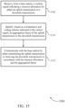
- a UE 115 may receive, from a base station 105, a control signal indicating a resource allocation for either an uplink transmission or a downlink transmission.
- the UE 115 may identify, based at least in part on a modulation and coding scheme indicated in the control signal, an aggregation factor of the uplink transmission or the downlink transmission.
- the UE 115 may communicate with the base station 105 by either transmitting the uplink transmission or receiving the downlink transmission in accordance with the resource allocation and the aggregation factor.
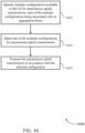
- a UE 115 identifies multiple configurations available to the UE for autonomous uplink transmissions, each of the multiple configurations being associated with an aggregation factor.
- the UE 115 selects one of the multiple configurations for autonomous uplink transmissions.
- the UE 115 transmits the autonomous uplink transmissions in accordance with the selected configuration.
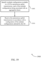
- a UE 115 may identify multiple configurations for monitoring repetition-based channel state reference signals.
- the UE 115 may receive a control signal that is indicative of a designated configuration to be used by the UE for monitoring repetition-based channel state reference signals, the designated configuration being one of the multiple configurations.
- the UE 115 may identify an aggregation factor based at least in part on the control signal or the designated configuration.
- the UE 115 may monitor repetition-based channel state reference signals based at least in part on at least one of the designated configuration or the aggregation factor.
- a base station 105 identifies multiple configurations available to a UE 115 for autonomous uplink transmissions, each of the multiple configurations being associated with an aggregation factor.
- the base station 105 receives the autonomous uplink transmissions in accordance with a configuration of the multiple configurations selected by the UE 115.
- a base station 105 may identify multiple configurations for monitoring repetition-based channel state reference signals.
- the base station 105 may transmit a control signal to a UE 115 that is indicative of a designated configuration to be used by the UE 115 for monitoring repetition-based channel state reference signals, the designated configuration being one of the multiple configurations, wherein at least one of the control signal or the designated configuration being indicative of an aggregation factor.
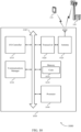
- wireless communication system 200 may be configured to support various communication modes between base station 205 and UE 210.
- the communication modes may include uplink communications from UE 210 to base station 205 and/or downlink communications from base station 205 to UE 210.
- wireless communications may be DCI-based where a control signal (e.g., DCI) carries or conveys the resources for the wireless communications.
- wireless communications may be aggregated.
- wireless communication system 200 may support aggregated uplink communications and/or aggregated downlink communications.
- aggregated communications generally include the uplink information and/or downlink information (e.g., such as a TB) being sent multiple times over multiple slots.
- the resource allocation e.g., time, frequency, and/or spatial resource
- aggregated communications typically have an associated aggregation factor that indicates the number of times that transmission of the information is to be repeated.
- the aggregation factor may also be considered a repetition factor for the wireless communications.
- the aggregation factor may be semi-statically configured and/or may be initiated by the DCI (e.g., dynamic).
- wireless communications may be grant-free communications, such as AUL communications.
- base station 205 may select resources (e.g., time, frequency, spatial, and the like) as well as various communication parameters for the uplink transmission.
- base station 205 may know or otherwise determine which aggregation factor is to be used for the uplink transmissions and select a corresponding MCS value as one of the communication parameters.
- base station 205 may configure a control signal (e.g., a DCI) to carry or otherwise convey an indication of the resource grant or allocation as well as an indication of the various communication parameters (including the selected MCS).
- UE 210 may receive the control signal and identify, based on the MCS, the aggregation factor to be used for the uplink transmission.
- UE 210 may access a look up table or other configured set of information to determine which aggregation factor is associated with the indicated MCS. Accordingly, UE 210 may transmit the uplink transmissions to base station 205 using the indicated resource allocations and communication parameters, with the aggregation factor for the uplink transmission being based on the indicated MCS.
- the available MCS values may be based at least in part on the number of available aggregation factors.
- UE 210 may support various aggregation factors in order to meet certain redundancy or reliability requirements. In some aspects, this may include a particularly high redundancy or reliability requirement being associated with lower MCS values (e.g., reliability may be favored over throughput). Accordingly, in some aspects high MCS values may be removed from the available MCS values (e.g., MCS tables), with lower MCS value(s) being added. In some aspects, each of the new lower MCS values may be associated with or otherwise correspond to a particular aggregation factor. In some aspects, a new MCS table may be used, with the MCS values in the new MCS table being associated with corresponding aggregation factors.
- dynamically signaling the aggregation factor in the DCI may provide a mechanism to dynamically change the aggregation factor for wireless communications.
- aspects of the described techniques provide a mechanism to dynamically change the aggregation factor.
- UE 210 is configured with a plurality of configurations to use for AUL transmissions. Generally, each AUL configuration has an associated or corresponding aggregation factor. Accordingly, UE 210, by selecting a particular configuration to use for an AUL transmission, implicitly selects the aggregation factor to be used for the AUL transmission.
- UE 210 may select a first configuration that corresponds to a first aggregation factor and perform the AUL transmission according to the first configuration with the corresponding first aggregation factor.
- UE 210 may select the configuration based on a variety of factors, e.g., based on a transport block size, the MCS, a starting symbol for the AUL transmission, and the like.
- base station 205 receives the AUL transmission on a configured set of resources (e.g. according to the configuration selected by UE 210) and identifies or otherwise determines the aggregation factor to be used during the AUL transmission based on the configured set of resources.
- the new entries may be added to the current CQI tables (e.g., by removing some indices associated with higher special efficiencies) or by implementing a new CQI table.
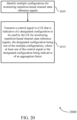
- UE 210 may measure the channel quality and determine, based on the channel quality, a CQI that is associated with the quality threshold and requested aggregation factor. Generally, transmissions from base station 205 to the UE 210 using the requested aggregation factor may be expected or otherwise configured to satisfy the quality threshold. In some aspects, UE 210 may transmit the CQI to the base station 205, with the MCS indicated in the control signal corresponding to the requested aggregation factor associated with the CQI.
- aspects of the described techniques provide improved mechanisms to support signaling repeated reference signal information for use during a downlink transmission.
- multiple configurations e.g., CSI-RS configurations
- each configuration may be associated with UE 210 monitoring repetition-based channel state reference signals (e.g., CSI-RSs).
- each configuration may be associated with or otherwise correspond to a particular aggregation factor. As one example, if the aggregation factor is set to 4, one of the available configurations may include resources or other information to support the reference signals and for repetition instances.
- the particular configuration to be used by UE 210 may be explicitly signaled in the DCI and/or implicitly indicated based on the aggregation factor.
- the CSI-RSs in different repetition instances can either be used for coherent channel estimation or non-coherent channel estimation. For example, coherent combining may be useful in the low mobility scenarios, whereas non-coherent may be more suitable for high mobility scenarios.
- all CSI-RSs may be signaled to be combined, not combined, or only a subset of the CSI-RSs may be combined.
- UE 210 may determine or otherwise identify the configurations available for monitoring the repetition-based channel state reference signals. UE 210 may then receive a control signal that carries or conveys or is otherwise associated with the designated configuration to be used by UE 210 for monitoring the repetition-based channel state reference signals. UE 210 may identify or otherwise select an aggregation factor based on the control signal or based on the designated configuration. UE 210 may monitor the repetition-based channel state reference signals according to the designated configuration and/or the aggregation factor.
- a first option may include restricting the monitoring occasion (e.g., when UE 210 monitors for a control signal, such as a DCI, from base station 205) to predefined locations, e.g., once every 2 symbols for repetition within a 2-symbol mini slot.
- the monitoring occasions may not be protected, but the first symbol of the repetition bundle is only allowed to start at some given locations.
- the given locations are a function of the mini slot length.
- options one and two may be performed for a mini-slot configuration or configurations having any number of available symbols.
- UE 210 may be asked to follow the behavior for the first option or the second option for different mini-slot links simultaneously, e.g., uplink transmissions with repetition and 2-symbol mini-slots and 7-symbol mini-slots. If UE 210 detects DCIs with their associated uplink transmissions overlapping, this may be interpreted as either an error case or as base station 205 overriding its first decision, e.g., the second DCI should be followed by UE 210.
- UE 210 is informed about the control region size of the next slot and the slot format of the next slot so that the mini-slot can be predetermined for the next slot (or slots).
- UE 210 may determine the mini-slots for the next slot only after decoding the slot format and the control region size of the next slot.
- the described techniques may provide for improved reference signal sharing for uplink transmission repetition.
- multiple reference signal configurations e.g., demodulation reference signal (DMRS) configurations
- DMRS demodulation reference signal
- each reference signal configuration may be associated with a particular aggregation factor.
- One of the reference signal configurations may be signaled by the DCI explicitly or could be implicitly indicated via the aggregation factor.
- UE 210 may be able to identify the aggregation factor based on the DMRS pattern configuration (e.g., reference signal configuration) conveyed by base station 205 and a control signal (e.g., the DCI).
- the indication may be similar to the indication discussed with respect to the CSI-RS features, e.g., either multiple configurations with different lengths, or multiple configurations with the length of the maximum aggregation factor supported.
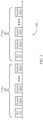
- slot configuration 300 illustrates an example of aggregated communications where the same information (e.g., a transport block) is communicated across a plurality of slots.
- slot configuration 300 includes a first slot 305 and a second slot 310.
- the first slot 305 and the second slot 310 may each include a plurality of symbols, with n symbols being shown by way of example only.
- the first slot 305 may include a first symbol 315 that carries or conveys a control signal (e.g., a DCI) and then a plurality of additional symbols 320 that may carry or convey data.
- the second slot 310 may include a first symbol 325 that carries or conveys a control signal (e.g., a DCI) and then a plurality of additional symbols 330 that may carry or convey data.
- wireless communications may be configured to support aggregation where the same information is transmitted across one or more symbols of a plurality of slots.
- a control signal e.g., the DCI conveyed during the first symbol 315 of the first slot 305
- the aggregation factor (or AL) may generally be considered the number of times of the information is transmitted.
- the wireless communications may refer to the uplink communications and/or downlink communications that are configured or otherwise activated by the control signal.
- the control signal may carry or convey an indication of resources to be used for the wireless communications (e.g., time, frequency, spatial, and the like, resources).
- a control signal carried in the first symbol 315 of the first slot 305 may configure wireless communications using resources corresponding to symbol 320-a and 320-b of the first slot 305, with the same information being repeated in symbol 330-a and symbol 330-b of the second slot 310.
- Other configurations of the symbols 320 and/or 330 may also be configured or otherwise activated for the wireless communications. In this example, the aggregation factor would be considered two.
- the described techniques provide a mechanism whereby an indication of the aggregation factor is implicitly conveyed in the control signal.
- a base station may configure a control signal to carry or convey an indication of an aggregation factor being used for the wireless communications (e.g., uplink communications and/or downlink communications). In some aspects, this may include the control signal carrying or conveying an indication of an MCS to be used for the wireless communications.
- the base station and UE may know that the MCS is associated with or otherwise corresponds to a particular aggregation factor. Accordingly, the control signal conveying an indication of a MCS (as well as of the resources being allocated for the transmission) implicitly conveys an indication of the aggregation factor to be used for the wireless communications. Therefore, the UE may use the indication of the MCS to identify the aggregation factor and communicate with a base station in accordance with the resources allocated in the control signal and the identified aggregation factor.
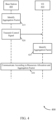
- FIG. 4 illustrates an example of a process 400 that supports aggregation factor associations in uplink and downlink transmissions not covered by the appended claims.
- process 400 may implement aspects of wireless communication systems 100, 200 and/or slot configuration 300. Aspects of process 400 may be implemented by a base station 405 and/or UE 410, which may be examples of corresponding devices described herein.
- base station 405 may transmit (and UE 410 may receive) a control signal indicating a resource allocation for each of the uplink transmission of the downlink transmission.
- the control signal may indicate a MCS to be used for the uplink transmission for the downlink transmission, with the MCS being associated with an aggregation factor.
- the control signal may dynamically indicate the aggregation factor.
- UE 410 may monitor for the control signal at predefined symbol locations within a slot (or mini-slot). In some aspects, the predefined symbol locations may be associated with the length of one or more mini-slots in the slot.
- UE 410 may identify, based at least in part on the MCS indicated in the control signal, the aggregation factor of the uplink transmission or the downlink transmission. In some aspects, this may include UE 410 identifying that the MCS indicated in the control signal is associated with the aggregation factor.
- this may include UE 410 receiving multiple control signals from the base station 405, with each control signal indicating different resource allocations for communicating with base station 405.
- UE 410 may determine that the resource allocations from the multiple control signals overlap and communicate with the base station 405 using the resource allocation from the last of the multiple control signals.
- this may include UE 410 identifying that repetitions of either the uplink transmission of the downlink transmission will span more than one slot.
- Base station 405 may transmit (and UE 410 may receive) a configuration regarding the future slot to be spanned by the uplink transmission or the downlink transmission and identify, based on the configuration information, one or more mini-slots to be used in the future slot for the uplink transmission or the downlink transmission.
- this may include UE 410 identifying a repetition of either the uplink transmission or the downlink transmission will span more than one slot.
- UE 410 may decode a slot format and a control region size of a future slot to be spanned by the uplink transmission or the downlink transmission and identify, based on the decoding, one or more mini-slots to be used in the future slot for the uplink transmission for the downlink transmission.
- this may include UE 410 identifying a DMRS configuration to be used in association with the communicating.
- the DMRS configuration may be associated with the aggregation factor. Accordingly, UE 410 may identify the DMRS configuration by receiving an indication of the DMRS configuration in the control signal and/or by determining DMRS configuration based on the aggregation factor.
- this may include UE 410 measuring a channel quality and determining, based on the channel quality a channel quality indicator that is associated with the quality threshold and a requested aggregation factor. In some aspects, transmission to UE 410 using the requested aggregation factor may be expected by the UE 410 to satisfy the quality threshold. In some aspects, this may include UE 410 transmitting (and base station 405 receiving) the channel quality indicator, where the MCS indicated in the control signal is based at least in part on the requested aggregation factor associated with a channel quality indicator. In some aspects, UE 410 may determine the channel quality indicator by selecting the channel quality indicator from a table or from a portion of a table whose entries are each associated with the respective aggregation factors. That is, in some aspects each available channel quality indicator may have a corresponding or otherwise associated aggregation factor.
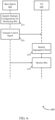
- FIG. 5 illustrates an example of a process 500 that supports aggregation factor associations in uplink and downlink transmissions in accordance with aspects of the present disclosure.
- process 500 may implement aspects of wireless communication systems 100, 200 and/or slot configuration 300. Aspects of process 500 may be implemented by a base station 505 and/or UE 510, which may be examples of the corresponding devices described herein.
- base station 505 identifies multiple configurations available to UE 510 to use for AUL transmissions, each of the multiple configurations being associated with a corresponding aggregation factor.
- UE 510 identifies multiple configurations available to UE 510 to use for AUL transmissions, each of the multiple configurations being associated with the corresponding aggregation factor.
- UE 510 transmits (and base station 505 receives) the AUL transmissions in accordance with the selected configuration. Accordingly, aspects of process 500 illustrate a mechanism where the aggregation factor may be change dynamically.
- FIG. 6 illustrates an example of a process 600 that supports aggregation factor associations in uplink and downlink transmissions not covered by the appended claims.
- process 600 may implement aspects of wireless communication systems 100, 200 and/or slot configuration 300. Aspects of process 600 may be implemented by a base station 605 and/or a UE 610, which may be examples of corresponding devices described herein.
- base station 605 may transmit (and UE 610 may receive) a control signal that is indicative of the designated configuration to be used by UE 610 for monitoring repetition-based channel state reference signals.
- the designated configuration may be one of the multiple configurations.
- the control signal and/or the designated configuration may be indicative of an aggregation factor. In some aspects, this may include UE 610 receiving the explicit indication of the designated configuration and the control signal. In some aspects, this may include UE 410 identifying that this is the configuration based on the aggregation factor.
- UE 610 may identify the aggregation factor based on the control signal and/or the designated configuration. In some aspects, this may include UE 610 monitoring only a number of signals associated with the aggregation factor regardless of a number of repetitions included in the designated configuration.
- UE 610 may monitor repetition-based channel state reference signals based at least in part on the designated configuration and/or the aggregation factor. In some aspects, this may include base station 605 transmitting (and UE 610 receiving) a signal indicating that UE 610 is to combined none, some, or all of the repetition base channel state reference signals.
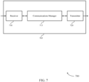
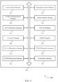
- FIG. 7 shows a block diagram 700 of a device 705 that supports aggregation factor associations in uplink and downlink transmissions in accordance with aspects of the present disclosure.
- the device 705 may be an example of aspects of a UE 115 as described herein.
- the device 705 may include a receiver 710, a communications manager 715, and a transmitter 720.
- the device 705 may also include a processor. Each of these components may be in communication with one another (e.g., via one or more buses).
- the receiver 710 may receive information such as packets, user data, or control information associated with various information channels (e.g., control channels, data channels, and information related to aggregation factor associations in uplink and downlink transmissions, etc.). Information may be passed on to other components of the device 705.
- the receiver 710 may be an example of aspects of the transceiver 1020 described with reference to FIG. 10 .
- the receiver 710 may utilize a single antenna or a set of antennas.
- the communications manager 715 may receive, from a base station, a control signal indicating a resource allocation for either an uplink transmission or a downlink transmission, identify, based on a modulation and coding scheme indicated in the control signal, an aggregation factor of the uplink transmission or the downlink transmission, and communicate with the base station by either transmitting the uplink transmission or receiving the downlink transmission in accordance with the resource allocation and the aggregation factor.
- the communications manager 715 may also identify multiple configurations available to the UE for autonomous uplink transmissions, each of the multiple configurations being associated with an aggregation factor, select one of the multiple configurations for autonomous uplink transmissions, and transmit the autonomous uplink transmissions in accordance with the selected configuration.
- the communications manager 715 may also identify multiple configurations for monitoring repetition-based channel state reference signals, receive a control signal that is indicative of a designated configuration to be used by the UE for monitoring repetition-based channel state reference signals, the designated configuration being one of the multiple configurations, identify an aggregation factor based on the control signal or the designated configuration, and monitor repetition-based channel state reference signals based on at least one of the designated configuration or the aggregation factor.
- the communications manager 715 may be an example of aspects of the communications manager 1010 described herein.
- the communications manager 715 may be implemented in hardware, code (e.g., software or firmware) executed by a processor, or any combination thereof. If implemented in code executed by a processor, the functions of the communications manager 715, or its sub-components may be executed by a general-purpose processor, a DSP, an application-specific integrated circuit (ASIC), a FPGA or other programmable logic device, discrete gate or transistor logic, discrete hardware components, or any combination thereof designed to perform the functions described in the present disclosure.
- code e.g., software or firmware
- ASIC application-specific integrated circuit
- FPGA field-programmable gate
- the communications manager 715 may be physically located at various positions, including being distributed such that portions of functions are implemented at different physical locations by one or more physical components.
- the communications manager 715, or its sub-components may be a separate and distinct component in accordance with various aspects of the present disclosure.
- the communications manager 715, or its sub-components may be combined with one or more other hardware components, including but not limited to an input/output (I/O) component, a transceiver, a network server, another computing device, one or more other components described in the present disclosure, or a combination thereof in accordance with various aspects of the present disclosure.
- I/O input/output
- the transmitter 720 may transmit signals generated by other components of the device 705.
- the transmitter 720 may be collocated with a receiver 710 in a transceiver module.
- the transmitter 720 may be an example of aspects of the transceiver 1020 described with reference to FIG. 10 .
- the transmitter 720 may utilize a single antenna or a set of antennas.
- FIG. 8 shows a block diagram 800 of a device 805 that supports aggregation factor associations in uplink and downlink transmissions in accordance with aspects of the present disclosure.
- the device 805 may be an example of aspects of a device 705, or a UE 115 as described herein.
- the device 805 may include a receiver 810, a communications manager 815, and a transmitter 850.
- the device 805 may also include a processor. Each of these components may be in communication with one another (e.g., via one or more buses).
- the receiver 810 may receive information such as packets, user data, or control information associated with various information channels (e.g., control channels, data channels, and information related to aggregation factor associations in uplink and downlink transmissions, etc.). Information may be passed on to other components of the device 805.
- the receiver 810 may be an example of aspects of the transceiver 1020 described with reference to FIG. 10 .
- the receiver 810 may utilize a single antenna or a set of antennas.
- the communications manager 815 may be an example of aspects of the communications manager 715 as described herein.
- the communications manager 815 may include a control signal manager 820, an aggregation factor manager 825, an UL/DL communications manager 830, an AUL configuration manager 835, a CSI-RS repetition manager 840, and a CSI-RS monitoring manager 845.
- the communications manager 815 may be an example of aspects of the communications manager 1010 described herein.
- the control signal manager 820 may receive, from a base station, a control signal indicating a resource allocation for either an uplink transmission or a downlink transmission.
- the aggregation factor manager 825 may identify, based on a modulation and coding scheme indicated in the control signal, an aggregation factor of the uplink transmission or the downlink transmission.
- the UL/DL communications manager 830 may communicate with the base station by either transmitting the uplink transmission or receiving the downlink transmission in accordance with the resource allocation and the aggregation factor.
- the AUL configuration manager 835 may identify multiple configurations available to the UE for autonomous uplink transmissions, each of the multiple configurations being associated with an aggregation factor and select one of the multiple configurations for autonomous uplink transmissions.
- the UL/DL communications manager 830 may transmit the autonomous uplink transmissions in accordance with the selected configuration.
- the CSI-RS repetition manager 840 may identify multiple configurations for monitoring repetition-based channel state reference signals.
- the control signal manager 820 may receive a control signal that is indicative of a designated configuration to be used by the UE for monitoring repetition-based channel state reference signals, the designated configuration being one of the multiple configurations.
- the aggregation factor manager 825 may identify an aggregation factor based on the control signal or the designated configuration.
- the CSI-RS monitoring manager 845 may monitor repetition-based channel state reference signals based on at least one of the designated configuration or the aggregation factor.
- the transmitter 850 may transmit signals generated by other components of the device 805.
- the transmitter 850 may be collocated with a receiver 810 in a transceiver module.
- the transmitter 850 may be an example of aspects of the transceiver 1020 described with reference to FIG. 10 .
- the transmitter 850 may utilize a single antenna or a set of antennas.
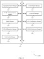
- FIG. 9 shows a block diagram 900 of a communications manager 905 that supports aggregation factor associations in uplink and downlink transmissions in accordance with aspects of the present disclosure.
- the communications manager 905 may be an example of aspects of a communications manager 715, a communications manager 815, or a communications manager 1010 described herein.
- the communications manager 905 may include a control signal manager 910, an aggregation factor manager 915, an UL/DL communications manager 920, a channel quality manager 925, a slot configuration manager 930, a mini-slot manager 935, a cross-slot manager 940, a DMRS manager 945, an AUL configuration manager 950, a CSI-RS repetition manager 955, a CSI-RS monitoring manager 960, and a combination manager 965. Each of these modules may communicate, directly or indirectly, with one another (e.g., via one or more buses).
- the control signal manager 910 may receive, from a base station, a control signal indicating a resource allocation for either an uplink transmission or a downlink transmission.
- control signal manager 910 may receive a control signal that is indicative of a designated configuration to be used by the UE for monitoring repetition-based channel state reference signals, the designated configuration being one of the multiple configurations. In some examples, the control signal manager 910 may receive an explicit indication of the designated configuration in the control signal. In some examples, the control signal manager 910 may identify the designated configuration based on the aggregation factor. In some examples, the control signal manager 910 may monitor only a number of signals associated with the aggregation factor regardless of a number of repetitions included in the designated configuration.
- the aggregation factor manager 915 may identify, based on a modulation and coding scheme indicated in the control signal, an aggregation factor of the uplink transmission or the downlink transmission. In some examples, the aggregation factor manager 915 may identify an aggregation factor based on the control signal or the designated configuration. In some examples, the aggregation factor manager 915 may identify that the modulation and coding scheme indicated in the control signal is associated with the aggregation factor. In some cases, the aggregation factor is dynamically indicated via the control signal.
- the UL/DL communications manager 920 may communicate with the base station by either transmitting the uplink transmission or receiving the downlink transmission in accordance with the resource allocation and the aggregation factor. In some examples, the UL/DL communications manager 920 may transmit the autonomous uplink transmissions in accordance with the selected configuration.
- the UL/DL communications manager 920 may transmit the uplink transmission or receiving the downlink transmission such that a first symbol of the uplink transmission or downlink transmission is transmitted or received only at predefined symbol locations within a slot or mini-slot, where the predefined symbol locations are associated with a length of one or more mini-slots in the slot.
- the UL/DL communications manager 920 may compare the resource allocation with the predefined symbol locations. In some examples, the UL/DL communications manager 920 may determine to communicate with the base station and in accordance with the resource allocation based on the comparing. In some examples, the UL/DL communications manager 920 may receive multiple control signals from the base station, each control signal indicating different resource allocations for communications with the base station.
- the UL/DL communications manager 920 may determine that the resource allocations from the multiple control signals overlap. In some examples, the UL/DL communications manager 920 may communicate with the base station using the resource allocation from a last of the multiple control signals.
- the AUL configuration manager 950 may identify multiple configurations available to the UE for autonomous uplink transmissions, each of the multiple configurations being associated with an aggregation factor. In some examples, the AUL configuration manager 950 may select one of the multiple configurations for autonomous uplink transmissions. In some examples, the AUL configuration manager 950 may select the one of the multiple configurations based on a transport block size, a modulation and coding scheme, a starting symbol for the autonomous uplink transmissions, or combinations thereof.
- the CSI-RS repetition manager 955 may identify multiple configurations for monitoring repetition-based channel state reference signals.
- the CSI-RS monitoring manager 960 may monitor repetition-based channel state reference signals based on at least one of the designated configuration or the aggregation factor.
- the channel quality manager 925 may measure channel quality. In some examples, the channel quality manager 925 may determine, based at least on the measured channel quality, a channel quality indicator that is associated with a quality threshold and a requested aggregation factor, where transmissions to the UE using the requested aggregation factor are expected by the UE to satisfy the quality threshold.
- the channel quality manager 925 may transmit the channel quality indicator to the base station, where the modulation and coding scheme indicated in the control signal is based on the requested aggregation factor associated with the channel quality indicator.
- the channel quality manager 925 may select the channel quality indicator from a table or from a portion of a table whose entries are each associated with respective aggregation factors.
- the slot configuration manager 930 may monitor for the control signal at predefined symbol locations within a slot or mini-slot, where the predefined symbol locations are associated with a length of one or more mini-slots in the slot.
- the mini-slot manager 935 may identify that repetitions of either the uplink transmission or the downlink transmission will span more than one slot.
- the mini-slot manager 935 may receive configuration information regarding a future slot to be spanned by the uplink transmission or the downlink transmission.
- the cross-slot manager 940 may identify that repetitions of either the uplink transmission or the downlink transmission will span more than one slot.
- the cross-slot manager 940 may decode a slot format and control region size of a future slot to be spanned by the uplink transmission or the downlink transmission. In some examples, the cross-slot manager 940 may identify, based on the decoding, one or more mini-slots to be used in the future slot for the uplink transmission or the downlink transmission.
- the DMRS manager 945 may identify a demodulation reference signal configuration to be used in association with the communicating, where the demodulation reference signal configuration is associated with the aggregation factor.
- the DMRS manager 945 may receive an indication of the demodulation reference signal configuration in the control signal. In some examples, the DMRS manager 945 may determine the demodulation reference signal configuration based on the aggregation factor.
- the combination manager 965 may receive a signal indicating that the UE is to combine none, some, or all of the repetition-based channel state reference signals.
- FIG. 10 shows a diagram of a system 1000 including a device 1005 that supports aggregation factor associations in uplink and downlink transmissions in accordance with aspects of the present disclosure.
- the device 1005 may be an example of or include the components of device 705, device 805, or a UE 115 as described herein.
- the device 1005 may include components for bi-directional voice and data communications including components for transmitting and receiving communications, including a communications manager 1010, an I/O controller 1015, a transceiver 1020, an antenna 1025, memory 1030, and a processor 1040. These components may be in electronic communication via one or more buses (e.g., bus 1045).
- buses e.g., bus 1045
- the communications manager 1010 may receive, from a base station, a control signal indicating a resource allocation for either an uplink transmission or a downlink transmission, identify, based on a modulation and coding scheme indicated in the control signal, an aggregation factor of the uplink transmission or the downlink transmission, and communicate with the base station by either transmitting the uplink transmission or receiving the downlink transmission in accordance with the resource allocation and the aggregation factor.
- the communications manager 1010 may also identify multiple configurations available to the UE for autonomous uplink transmissions, each of the multiple configurations being associated with an aggregation factor, select one of the multiple configurations for autonomous uplink transmissions, and transmit the autonomous uplink transmissions in accordance with the selected configuration.
- the communications manager 1010 may also identify multiple configurations for monitoring repetition-based channel state reference signals, receive a control signal that is indicative of a designated configuration to be used by the UE for monitoring repetition-based channel state reference signals, the designated configuration being one of the multiple configurations, identify an aggregation factor based on the control signal or the designated configuration, and monitor repetition-based channel state reference signals based on at least one of the designated configuration or the aggregation factor.
- the I/O controller 1015 may manage input and output signals for the device 1005.
- the I/O controller 1015 may also manage peripherals not integrated into the device 1005.
- the I/O controller 1015 may represent a physical connection or port to an external peripheral.
- the I/O controller 1015 may utilize an operating system such as iOS ® , ANDROID ® , MS-DOS ® , MS-WINDOWS ® , OS/2 ® , UNIX ® , LINUX ® , or another known operating system.
- the I/O controller 1015 may represent or interact with a modem, a keyboard, a mouse, a touchscreen, or a similar device.
- the I/O controller 1015 may be implemented as part of a processor.
- a user may interact with the device 1005 via the I/O controller 1015 or via hardware components controlled by the I/O controller 1015.
- the transceiver 1020 may communicate bi-directionally, via one or more antennas, wired, or wireless links as described above.
- the transceiver 1020 may represent a wireless transceiver and may communicate bi-directionally with another wireless transceiver.
- the transceiver 1020 may also include a modem to modulate the packets and provide the modulated packets to the antennas for transmission, and to demodulate packets received from the antennas.
- the wireless device may include a single antenna 1025. However, in some cases the device may have more than one antenna 1025, which may be capable of concurrently transmitting or receiving multiple wireless transmissions.
- the memory 1030 may include RAM and ROM.
- the memory 1030 may store computer-readable, computer-executable code 1035 including instructions that, when executed, cause the processor to perform various functions described herein.
- the memory 1030 may contain, among other things, a BIOS which may control basic hardware or software operation such as the interaction with peripheral components or devices.
- the processor 1040 may include an intelligent hardware device, (e.g., a general-purpose processor, a DSP, a CPU, a microcontroller, an ASIC, an FPGA, a programmable logic device, a discrete gate or transistor logic component, a discrete hardware component, or any combination thereof).
- the processor 1040 may be configured to operate a memory array using a memory controller.
- a memory controller may be integrated into the processor 1040.
- the processor 1040 may be configured to execute computer-readable instructions stored in a memory (e.g., the memory 1030) to cause the device 1005 to perform various functions (e.g., functions or tasks supporting aggregation factor associations in uplink and downlink transmissions).
- the code 1035 may include instructions to implement aspects of the present disclosure, including instructions to support wireless communications.
- the code 1035 may be stored in a non-transitory computer-readable medium such as system memory or other type of memory. In some cases, the code 1035 may not be directly executable by the processor 1040 but may cause a computer (e.g., when compiled and executed) to perform functions described herein.
- FIG. 11 shows a block diagram 1100 of a device 1105 that supports aggregation factor associations in uplink and downlink transmissions in accordance with aspects of the present disclosure.
- the device 1105 may be an example of aspects of a base station 105 as described herein.
- the device 1105 may include a receiver 1110, a communications manager 1115, and a transmitter 1120.
- the device 1105 may also include a processor. Each of these components may be in communication with one another (e.g., via one or more buses).
- the receiver 1110 may receive information such as packets, user data, or control information associated with various information channels (e.g., control channels, data channels, and information related to aggregation factor associations in uplink and downlink transmissions, etc.). Information may be passed on to other components of the device 1105.
- the receiver 1110 may be an example of aspects of the transceiver 1420 described with reference to FIG. 14 .
- the receiver 1110 may utilize a single antenna or a set of antennas.
- the communications manager 1115 may identify an aggregation factor associated with either an uplink transmission to be received from a UE or a downlink transmission to be transmitted to the UE, transmit, to the UE, a control signal indicating a resource allocation for either the uplink transmission or the downlink transmission, where the control signal indicates a modulation and coding scheme associated with the aggregation factor, and communicate with the UE by either receiving the uplink transmission or transmitting the downlink transmission in accordance with the resource allocation and the aggregation factor.
- the communications manager 1115 may also identify multiple configurations available to a UE for autonomous uplink transmissions, each of the multiple configurations being associated with an aggregation factor, receive the autonomous uplink transmissions in accordance with a configuration of the multiple configurations selected by the UE, identify multiple configurations for monitoring repetition-based channel state reference signals, and transmit a control signal to a UE that is indicative of a designated configuration to be used by the UE for monitoring repetition-based channel state reference signals, the designated configuration being one of the multiple configurations, where at least one of the control signal or the designated configuration being indicative of an aggregation factor.
- the communications manager 1115 may be an example of aspects of the communications manager 1410 described herein.
- the communications manager 1115 may be implemented in hardware, code (e.g., software or firmware) executed by a processor, or any combination thereof. If implemented in code executed by a processor, the functions of the communications manager 1115, or its sub-components may be executed by a general-purpose processor, a DSP, an application-specific integrated circuit (ASIC), a FPGA or other programmable logic device, discrete gate or transistor logic, discrete hardware components, or any combination thereof designed to perform the functions described in the present disclosure.
- code e.g., software or firmware
- ASIC application-specific integrated circuit
- FPGA field-programmable gate
- the communications manager 1115 may be physically located at various positions, including being distributed such that portions of functions are implemented at different physical locations by one or more physical components.
- the communications manager 1115, or its sub-components may be a separate and distinct component in accordance with various aspects of the present disclosure.
- the communications manager 1115, or its sub-components may be combined with one or more other hardware components, including but not limited to an input/output (I/O) component, a transceiver, a network server, another computing device, one or more other components described in the present disclosure, or a combination thereof in accordance with various aspects of the present disclosure.
- I/O input/output
- the transmitter 1120 may transmit signals generated by other components of the device 1105.
- the transmitter 1120 may be collocated with a receiver 1110 in a transceiver module.
- the transmitter 1120 may be an example of aspects of the transceiver 1420 described with reference to FIG. 14 .
- the transmitter 1120 may utilize a single antenna or a set of antennas.
- FIG. 12 shows a block diagram 1200 of a device 1205 that supports aggregation factor associations in uplink and downlink transmissions in accordance with aspects of the present disclosure.
- the device 1205 may be an example of aspects of a device 1105, or a base station 105 as described herein.
- the device 1205 may include a receiver 1210, a communications manager 1215, and a transmitter 1250.
- the device 1205 may also include a processor. Each of these components may be in communication with one another (e.g., via one or more buses).
- the receiver 1210 may receive information such as packets, user data, or control information associated with various information channels (e.g., control channels, data channels, and information related to aggregation factor associations in uplink and downlink transmissions, etc.). Information may be passed on to other components of the device 1205.
- the receiver 1210 may be an example of aspects of the transceiver 1420 described with reference to FIG. 14 .
- the receiver 1210 may utilize a single antenna or a set of antennas.
- the communications manager 1215 may be an example of aspects of the communications manager 1115 as described herein.
- the communications manager 1215 may include an aggregation factor manager 1220, a control signal manager 1225, an UL/DL communications manager 1230, an AUL configuration manager 1235, a CSI-RS repetition manager 1240, and a CSI-RS monitoring manager 1245.
- the communications manager 1215 may be an example of aspects of the communications manager 1410 described herein.
- the aggregation factor manager 1220 may identify an aggregation factor associated with either an uplink transmission to be received from a UE or a downlink transmission to be transmitted to the UE.
- the control signal manager 1225 may transmit, to the UE, a control signal indicating a resource allocation for either the uplink transmission or the downlink transmission, where the control signal indicates a modulation and coding scheme associated with the aggregation factor.
- the UL/DL communications manager 1230 may communicate with the UE by either receiving the uplink transmission or transmitting the downlink transmission in accordance with the resource allocation and the aggregation factor.
- the AUL configuration manager 1235 may identify multiple configurations available to a UE for autonomous uplink transmissions, each of the multiple configurations being associated with an aggregation factor and receive the autonomous uplink transmissions in accordance with a configuration of the multiple configurations selected by the UE.
- the CSI-RS repetition manager 1240 may identify multiple configurations for monitoring repetition-based channel state reference signals.
- the CSI-RS monitoring manager 1245 may transmit a control signal to a UE that is indicative of a designated configuration to be used by the UE for monitoring repetition-based channel state reference signals, the designated configuration being one of the multiple configurations, where at least one of the control signal or the designated configuration being indicative of an aggregation factor.
- the transmitter 1250 may transmit signals generated by other components of the device 1205.
- the transmitter 1250 may be collocated with a receiver 1210 in a transceiver module.
- the transmitter 1250 may be an example of aspects of the transceiver 1420 described with reference to FIG. 14 .
- the transmitter 1250 may utilize a single antenna or a set of antennas.
- FIG. 13 shows a block diagram 1300 of a communications manager 1305 that supports aggregation factor associations in uplink and downlink transmissions in accordance with aspects of the present disclosure.
- the communications manager 1305 may be an example of aspects of a communications manager 1115, a communications manager 1215, or a communications manager 1410 described herein.
- the communications manager 1305 may include an aggregation factor manager 1310, a control signal manager 1315, an UL/DL communications manager 1320, a cross-slot manager 1325, a DMRS manager 1330, an AUL configuration manager 1335, a CSI-RS repetition manager 1340, a CSI-RS monitoring manager 1345, and a combination manager 1350.
- Each of these modules may communicate, directly or indirectly, with one another (e.g., via one or more buses).
- the aggregation factor manager 1310 may identify an aggregation factor associated with either an uplink transmission to be received from a UE or a downlink transmission to be transmitted to the UE.
- the aggregation factor manager 1310 may receive a channel quality indicator from the UE, where the channel quality indicator is associated with a requested aggregation factor such that transmissions to the UE using the requested aggregation factor are expected by the UE to satisfy a quality threshold associated with the channel quality indicator.
- the aggregation factor manager 1310 may set the aggregation factor to be equal to the requested aggregation factor.
- the aggregation factor is dynamically indicated to the UE via the control signal.
- the channel quality indicator is from a table or from a portion of a table whose entries are each associated with respective aggregation factors.
- the control signal manager 1315 may transmit, to the UE, a control signal indicating a resource allocation for either the uplink transmission or the downlink transmission, where the control signal indicates a modulation and coding scheme associated with the aggregation factor.
- the UL/DL communications manager 1320 may communicate with the UE by either receiving the uplink transmission or transmitting the downlink transmission in accordance with the resource allocation and the aggregation factor.
- the UL/DL communications manager 1320 may receive the uplink transmission or transmitting the downlink transmission such that a first symbol of the uplink transmission or downlink transmission is received or transmitted only at predefined symbol locations within a slot or mini-slot, where the predefined symbol locations are associated with a length of one or more mini-slots in the slot.
- the AUL configuration manager 1335 may identify multiple configurations available to a UE for autonomous uplink transmissions, each of the multiple configurations being associated with an aggregation factor.
- the AUL configuration manager 1335 may receive the autonomous uplink transmissions in accordance with a configuration of the multiple configurations selected by the UE.
- the CSI-RS repetition manager 1340 may identify multiple configurations for monitoring repetition-based channel state reference signals.
- the CSI-RS monitoring manager 1345 may transmit a control signal to a UE that is indicative of a designated configuration to be used by the UE for monitoring repetition-based channel state reference signals, the designated configuration being one of the multiple configurations, where at least one of the control signal or the designated configuration being indicative of an aggregation factor.
- the CSI-RS monitoring manager 1345 may transmit an explicit indication of the designated configuration in the control signal.
- the cross-slot manager 1325 may identify that repetitions of either the uplink transmission or the downlink transmission will span more than one slot. In some examples, the cross-slot manager 1325 may transmit configuration information regarding a future slot to be spanned by the uplink transmission or the downlink transmission. In some examples, the cross-slot manager 1325 may identify, based on the configuration information, one or more mini-slots to be used in the future slot for the uplink transmission or the downlink transmission.
- the DMRS manager 1330 may identify a demodulation reference signal configuration to be used in association with the communicating, where the demodulation reference signal configuration is associated with the aggregation factor.
- the DMRS manager 1330 may transmit to the UE an indication of the demodulation reference signal configuration in the control signal.
- the combination manager 1350 may transmit a signal indicating that the UE is to combine none, some, or all of the repetition-based channel state reference signals.
- FIG. 14 shows a diagram of a system 1400 including a device 1405 that supports aggregation factor associations in uplink and downlink transmissions in accordance with aspects of the present disclosure.
- the device 1405 may be an example of or include the components of device 1105, device 1205, or a base station 105 as described herein.
- the device 1405 may include components for bi-directional voice and data communications including components for transmitting and receiving communications, including a communications manager 1410, a network communications manager 1415, a transceiver 1420, an antenna 1425, memory 1430, a processor 1440, and an inter-station communications manager 1445. These components may be in electronic communication via one or more buses (e.g., bus 1450).
- buses e.g., bus 1450
- the communications manager 1410 may identify an aggregation factor associated with either an uplink transmission to be received from a UE or a downlink transmission to be transmitted to the UE, transmit, to the UE, a control signal indicating a resource allocation for either the uplink transmission or the downlink transmission, where the control signal indicates a modulation and coding scheme associated with the aggregation factor, and communicate with the UE by either receiving the uplink transmission or transmitting the downlink transmission in accordance with the resource allocation and the aggregation factor.
- the communications manager 1410 may also identify multiple configurations available to a UE for autonomous uplink transmissions, each of the multiple configurations being associated with an aggregation factor, receive the autonomous uplink transmissions in accordance with a configuration of the multiple configurations selected by the UE, identify multiple configurations for monitoring repetition-based channel state reference signals, and transmit a control signal to a UE that is indicative of a designated configuration to be used by the UE for monitoring repetition-based channel state reference signals, the designated configuration being one of the multiple configurations, where at least one of the control signal or the designated configuration being indicative of an aggregation factor.
- the network communications manager 1415 may manage communications with the core network (e.g., via one or more wired backhaul links). For example, the network communications manager 1415 may manage the transfer of data communications for client devices, such as one or more UEs 115.
- the transceiver 1420 may communicate bi-directionally, via one or more antennas, wired, or wireless links as described above.
- the transceiver 1420 may represent a wireless transceiver and may communicate bi-directionally with another wireless transceiver.
- the transceiver 1420 may also include a modem to modulate the packets and provide the modulated packets to the antennas for transmission, and to demodulate packets received from the antennas.
- the wireless device may include a single antenna 1425. However, in some cases the device may have more than one antenna 1425, which may be capable of concurrently transmitting or receiving multiple wireless transmissions.
- the memory 1430 may include RAM, ROM, or a combination thereof.
- the memory 1430 may store computer-readable code 1435 including instructions that, when executed by a processor (e.g., the processor 1440) cause the device to perform various functions described herein.
- a processor e.g., the processor 1440
- the memory 1430 may contain, among other things, a BIOS which may control basic hardware or software operation such as the interaction with peripheral components or devices.
- the processor 1440 may include an intelligent hardware device, (e.g., a general-purpose processor, a DSP, a CPU, a microcontroller, an ASIC, an FPGA, a programmable logic device, a discrete gate or transistor logic component, a discrete hardware component, or any combination thereof).
- the processor 1440 may be configured to operate a memory array using a memory controller.
- a memory controller may be integrated into processor 1440.
- the processor 1440 may be configured to execute computer-readable instructions stored in a memory (e.g., the memory 1430) to cause the device 1405 to perform various functions (e.g., functions or tasks supporting aggregation factor associations in uplink and downlink transmissions).
- the inter-station communications manager 1445 may manage communications with other base station 105, and may include a controller or scheduler for controlling communications with UEs 115 in cooperation with other base stations 105. For example, the inter-station communications manager 1445 may coordinate scheduling for transmissions to UEs 115 for various interference mitigation techniques such as beamforming or joint transmission. In some examples, the inter-station communications manager 1445 may provide an X2 interface within an LTE/LTE-A wireless communication network technology to provide communication between base stations 105.
- the code 1435 may include instructions to implement aspects of the present disclosure, including instructions to support wireless communications.
- the code 1435 may be stored in a non-transitory computer-readable medium such as system memory or other type of memory. In some cases, the code 1435 may not be directly executable by the processor 1440 but may cause a computer (e.g., when compiled and executed) to perform functions described herein.
- FIG. 15 shows a flowchart illustrating a method 1500 that supports aggregation factor associations in uplink and downlink transmissions not covered by the appended claims.
- the operations of method 1500 may be implemented by a UE 115 or its components as described herein.
- the operations of method 1500 may be performed by a communications manager as described with reference to FIGs. 7 through 10 .
- a UE may execute a set of instructions to control the functional elements of the UE to perform the functions described below. Additionally or alternatively, a UE may perform aspects of the functions described below using special-purpose hardware.
- the UE may receive, from a base station, a control signal indicating a resource allocation for either an uplink transmission or a downlink transmission.
- the operations of 1505 may be performed according to the methods described herein. In some examples, aspects of the operations of 1505 may be performed by a control signal manager as described with reference to FIGs. 7 through 10 .
- the UE may identify, based on a modulation and coding scheme indicated in the control signal, an aggregation factor of the uplink transmission or the downlink transmission.
- the operations of 1510 may be performed according to the methods described herein. In some examples, aspects of the operations of 1510 may be performed by an aggregation factor manager as described with reference to FIGs. 7 through 10 .
- the UE may communicate with the base station by either transmitting the uplink transmission or receiving the downlink transmission in accordance with the resource allocation and the aggregation factor.
- the operations of 1515 may be performed according to the methods described herein. In some examples, aspects of the operations of 1515 may be performed by an UL/DL communications manager as described with reference to FIGs. 7 through 10 .
- FIG. 16 shows a flowchart illustrating a method 1600 that supports aggregation factor associations in uplink and downlink transmissions in accordance with aspects of the present disclosure.
- the operations of method 1600 may be implemented by a UE 115 or its components as described herein.
- the operations of method 1600 may be performed by a communications manager as described with reference to FIGs. 7 through 10 .
- a UE may execute a set of instructions to control the functional elements of the UE to perform the functions described below. Additionally or alternatively, a UE may perform aspects of the functions described below using special-purpose hardware.
- the UE may identify multiple configurations available to the UE for autonomous uplink transmissions, each of the multiple configurations being associated with an aggregation factor.
- the operations of 1605 may be performed according to the methods described herein. In some examples, aspects of the operations of 1605 may be performed by an AUL configuration manager as described with reference to FIGs. 7 through 10 .
- the UE may select one of the multiple configurations for autonomous uplink transmissions.
- the operations of 1610 may be performed according to the methods described herein. In some examples, aspects of the operations of 1610 may be performed by an AUL configuration manager as described with reference to FIGs. 7 through 10 .
- the UE may transmit the autonomous uplink transmissions in accordance with the selected configuration.
- the operations of 1615 may be performed according to the methods described herein. In some examples, aspects of the operations of 1615 may be performed by an UL/DL communications manager as described with reference to FIGs. 7 through 10 .
- FIG. 17 shows a flowchart illustrating a method 1700 that supports aggregation factor associations in uplink and downlink transmissions not covered by the appended claims.
- the operations of method 1700 may be implemented by a UE 115 or its components as described herein.
- the operations of method 1700 may be performed by a communications manager as described with reference to FIGs. 7 through 10 .
- a UE may execute a set of instructions to control the functional elements of the UE to perform the functions described below. Additionally or alternatively, a UE may perform aspects of the functions described below using special-purpose hardware.
- the UE may identify multiple configurations for monitoring repetition-based channel state reference signals.
- the operations of 1705 may be performed according to the methods described herein. In some examples, aspects of the operations of 1705 may be performed by a CSI-RS repetition manager as described with reference to FIGs. 7 through 10 .
- the UE may receive a control signal that is indicative of a designated configuration to be used by the UE for monitoring repetition-based channel state reference signals, the designated configuration being one of the multiple configurations.
- the operations of 1710 may be performed according to the methods described herein. In some examples, aspects of the operations of 1710 may be performed by a control signal manager as described with reference to FIGs. 7 through 10 .
- the UE may identify an aggregation factor based on the control signal or the designated configuration.
- the operations of 1715 may be performed according to the methods described herein. In some examples, aspects of the operations of 1715 may be performed by an aggregation factor manager as described with reference to FIGs. 7 through 10 .
- the UE may monitor repetition-based channel state reference signals based on at least one of the designated configuration or the aggregation factor.
- the operations of 1720 may be performed according to the methods described herein. In some examples, aspects of the operations of 1720 may be performed by a CSI-RS monitoring manager as described with reference to FIGs. 7 through 10 .
- FIG. 18 shows a flowchart illustrating a method 1800 that supports aggregation factor associations in uplink and downlink transmissions not covered by the appended claims.
- the operations of method 1800 may be implemented by a base station 105 or its components as described herein.
- the operations of method 1800 may be performed by a communications manager as described with reference to FIGs. 11 through 14 .
- a base station may execute a set of instructions to control the functional elements of the base station to perform the functions described below. Additionally or alternatively, a base station may perform aspects of the functions described below using special-purpose hardware.
- the base station may identify an aggregation factor associated with either an uplink transmission to be received from a UE or a downlink transmission to be transmitted to the UE.
- the operations of 1805 may be performed according to the methods described herein. In some examples, aspects of the operations of 1805 may be performed by an aggregation factor manager as described with reference to FIGs. 11 through 14 .
- the base station may transmit, to the UE, a control signal indicating a resource allocation for either the uplink transmission or the downlink transmission, where the control signal indicates a modulation and coding scheme associated with the aggregation factor.
- the operations of 1810 may be performed according to the methods described herein. In some examples, aspects of the operations of 1810 may be performed by a control signal manager as described with reference to FIGs. 11 through 14 .
- the base station may communicate with the UE by either receiving the uplink transmission or transmitting the downlink transmission in accordance with the resource allocation and the aggregation factor.
- the operations of 1815 may be performed according to the methods described herein. In some examples, aspects of the operations of 1815 may be performed by an UL/DL communications manager as described with reference to FIGs. 11 through 14 .
- FIG. 19 shows a flowchart illustrating a method 1900 that supports aggregation factor associations in uplink and downlink transmissions in accordance with aspects of the present disclosure.
- the operations of method 1900 may be implemented by a base station 105 or its components as described herein.
- the operations of method 1900 may be performed by a communications manager as described with reference to FIGs. 11 through 14 .
- a base station may execute a set of instructions to control the functional elements of the base station to perform the functions described below. Additionally or alternatively, a base station may perform aspects of the functions described below using special-purpose hardware.
- the base station may identify multiple configurations available to a UE for autonomous uplink transmissions, each of the multiple configurations being associated with an aggregation factor.
- the operations of 1905 may be performed according to the methods described herein. In some examples, aspects of the operations of 1905 may be performed by an AUL configuration manager as described with reference to FIGs. 11 through 14 .
- FIG. 20 shows a flowchart illustrating a method 2000 that supports aggregation factor associations in uplink and downlink transmissions not covered by the appended claims.
- the operations of method 2000 may be implemented by a base station 105 or its components as described herein.
- the operations of method 2000 may be performed by a communications manager as described with reference to FIGs. 11 through 14 .
- a base station may execute a set of instructions to control the functional elements of the base station to perform the functions described below. Additionally or alternatively, a base station may perform aspects of the functions described below using special-purpose hardware.
- the base station may identify multiple configurations for monitoring repetition-based channel state reference signals.
- the operations of 2005 may be performed according to the methods described herein. In some examples, aspects of the operations of 2005 may be performed by a CSI-RS repetition manager as described with reference to FIGs. 11 through 14 .
- the base station may transmit a control signal to a UE that is indicative of a designated configuration to be used by the UE for monitoring repetition-based channel state reference signals, the designated configuration being one of the multiple configurations, where at least one of the control signal or the designated configuration being indicative of an aggregation factor.
- the operations of 2010 may be performed according to the methods described herein. In some examples, aspects of the operations of 2010 may be performed by a CSI-RS monitoring manager as described with reference to FIGs. 11 through 14 .
- CDMA code division multiple access
- TDMA time division multiple access
- FDMA frequency division multiple access
- OFDMA orthogonal frequency division multiple access
- SC-FDMA single carrier frequency division multiple access
- a CDMA system may implement a radio technology such as CDMA2000, Universal Terrestrial Radio Access (UTRA), etc.
- CDMA2000 covers IS-2000, IS-95, and IS-856 standards.
- IS-2000 Releases may be commonly referred to as CDMA2000 1X, 1X, etc.
- IS-856 TIA-856) is commonly referred to as CDMA2000 1xEV-DO, High Rate Packet Data (HRPD), etc.
- UTRA includes Wideband CDMA (WCDMA) and other variants of CDMA.
- a TDMA system may implement a radio technology such as Global System for Mobile Communications (GSM).
- GSM Global System for Mobile Communications
- An OFDMA system may implement a radio technology such as Ultra Mobile Broadband (UMB), Evolved UTRA (E-UTRA), Institute of Electrical and Electronics Engineers (IEEE) 802.11 (Wi-Fi), IEEE 802.16 (WiMAX), IEEE 802.20, Flash-OFDM, etc.
- UMB Ultra Mobile Broadband
- E-UTRA Evolved UTRA
- IEEE Institute of Electrical and Electronics Engineers
- Wi-Fi Wi-Fi
- WiMAX IEEE 802.16
- IEEE 802.20 Flash-OFDM
- UTRA and E-UTRA are part of Universal Mobile Telecommunications System (UMTS).
- LTE, LTE-A, and LTE-A Pro are releases of UMTS that use E-UTRA.
- UTRA, E-UTRA, UMTS, LTE, LTE-A, LTE-A Pro, NR, and GSM are described in documents from the organization named "3rd Generation Partnership Project" (3GPP).
- CDMA2000 and UMB are described in documents from an organization named "3rd Generation Partnership Project 2" (3GPP2).
- 3GPP2 3rd Generation Partnership Project 2
- the techniques described herein may be used for the systems and radio technologies mentioned herein as well as other systems and radio technologies. While aspects of an LTE, LTE-A, LTE-A Pro, or NR system may be described for purposes of example, and LTE, LTE-A, LTE-A Pro, or NR terminology may be used in much of the description, the techniques described herein are applicable beyond LTE, LTE-A, LTE-A Pro, or NR applications.
- a macro cell generally covers a relatively large geographic area (e.g., several kilometers in radius) and may allow unrestricted access by UEs with service subscriptions with the network provider.
- a small cell may be associated with a lower-powered base station, as compared with a macro cell, and a small cell may operate in the same or different (e.g., licensed, unlicensed, etc.) frequency bands as macro cells.
- Small cells may include pico cells, femto cells, and micro cells according to various examples.
- a pico cell for example, may cover a small geographic area and may allow unrestricted access by UEs with service subscriptions with the network provider.
- a femto cell may also cover a small geographic area (e.g., a home) and may provide restricted access by UEs having an association with the femto cell (e.g., UEs in a closed subscriber group (CSG), UEs for users in the home, and the like).
- An eNB for a macro cell may be referred to as a macro eNB.
- An eNB for a small cell may be referred to as a small cell eNB, a pico eNB, a femto eNB, or a home eNB.
- An eNB may support one or multiple (e.g., two, three, four, and the like) cells, and may also support communications using one or multiple component carriers.
- the wireless communications systems described herein may support synchronous or asynchronous operation.
- the base stations may have similar frame timing, and transmissions from different base stations may be approximately aligned in time.
- the base stations may have different frame timing, and transmissions from different base stations may not be aligned in time.
- the techniques described herein may be used for either synchronous or asynchronous operations.
- Information and signals described herein may be represented using any of a variety of different technologies and techniques.
- data, instructions, commands, information, signals, bits, symbols, and chips that may be referenced throughout the description may be represented by voltages, currents, electromagnetic waves, magnetic fields or particles, optical fields or particles, or any combination thereof.
- a general-purpose processor may be a microprocessor, but in the alternative, the processor may be any conventional processor, controller, microcontroller, or state machine.
- a processor may also be implemented as a combination of computing devices (e.g., a combination of a DSP and a microprocessor, multiple microprocessors, one or more microprocessors in conjunction with a DSP core, or any other such configuration).
- the functions described herein may be implemented in hardware, software executed by a processor, firmware, or any combination thereof. If implemented in software executed by a processor, the functions may be stored on or transmitted over as one or more instructions or code on a computer-readable medium. Other examples and implementations are within the scope of the disclosure and appended claims. For example, due to the nature of software, functions described herein can be implemented using software executed by a processor, hardware, firmware, hardwiring, or combinations of any of these. Features implementing functions may also be physically located at various positions, including being distributed such that portions of functions are implemented at different physical locations.
- Computer-readable media includes both non-transitory computer storage media and communication media including any medium that facilitates transfer of a computer program from one place to another.
- a non-transitory storage medium may be any available medium that can be accessed by a general purpose or special purpose computer.
- non-transitory computer-readable media may include random-access memory (RAM), read-only memory (ROM), electrically erasable programmable ROM (EEPROM), flash memory, compact disk (CD) ROM or other optical disk storage, magnetic disk storage or other magnetic storage devices, or any other non-transitory medium that can be used to carry or store desired program code means in the form of instructions or data structures and that can be accessed by a general-purpose or special-purpose computer, or a general-purpose or special-purpose processor.
- RAM random-access memory
- ROM read-only memory
- EEPROM electrically erasable programmable ROM
- CD compact disk
- magnetic disk storage or other magnetic storage devices or any other non-transitory medium that can be used to carry or store
- any connection is properly termed a computer-readable medium.
- the software is transmitted from a website, server, or other remote source using a coaxial cable, fiber optic cable, twisted pair, digital subscriber line (DSL), or wireless technologies such as infrared, radio, and microwave
- the coaxial cable, fiber optic cable, twisted pair, DSL, or wireless technologies such as infrared, radio, and microwave are included in the definition of medium.
- Disk and disc include CD, laser disc, optical disc, digital versatile disc (DVD), floppy disk and Blu-ray disc where disks usually reproduce data magnetically, while discs reproduce data optically with lasers. Combinations of the above are also included within the scope of computer-readable media.
Landscapes
- Engineering & Computer Science (AREA)
- Signal Processing (AREA)
- Computer Networks & Wireless Communication (AREA)
- Quality & Reliability (AREA)
- Mobile Radio Communication Systems (AREA)
Claims (11)
- Verfahren zur drahtlosen Kommunikation an einem Benutzergerät, UE (115; 210; 510; 705; 805; 905; 1005), umfassend:Identifizieren (520; 1605) mehrerer Konfigurationen, die dem UE für autonome Uplink-Übertragungen zur Verfügung stehen, wobei jede der mehreren Konfigurationen mit einem entsprechenden Aggregationsfaktor assoziiert ist, der eine Anzahl angibt, wie oft eine Übertragung wiederholt werden soll, wobei zumindest zwei der mehreren Konfigurationen mit verschiedenen Aggregationsfaktoren assoziiert sind;Auswählen (525; 1610) einer der mehreren Konfigurationen für autonome Uplink-Übertragungen; undÜbertragen (530; 1615), an eine Basisstation (105; 205; 505; 1105; 1205; 1305; 1405), der autonomen Uplink-Übertragungen gemäß der ausgewählten Konfiguration,wobei das Übertragen der autonomen Uplink-Übertragungen gemäß der ausgewählten Konfiguration implizit der Basisstation angibt, dass der mit der ausgewählten Konfiguration assoziierte Aggregationsfaktor für die autonomen Uplink-Übertragungen verwendet werden soll; undwobei das Übertragen (530; 1615) der autonomen Uplink-Übertragungen umfasst:
Übertragen der autonomen Uplink-Übertragungen derart, dass ein erstes Symbol jeder autonomen Uplink-Übertragung nur an vordefinierten Symbolpositionen innerhalb eines Schlitzes oder Minischlitzes übertragen wird, wobei die vordefinierten Symbolpositionen mit einer Länge von einem oder mehreren Minischlitzen in dem Schlitz assoziiert sind. - Verfahren gemäß Anspruch 1, wobei das Auswählen (525; 1610) der einen der mehreren Konfigurationen umfasst:
Auswählen der einen der mehreren Konfigurationen zumindest teilweise basierend auf einer Transportblockgröße, einem Modulations- und Codierungsschema, einem Startsymbol für die autonomen Uplink-Übertragungen oder Kombinationen davon. - Verfahren gemäß Anspruch 1 oder 2, weiterhin umfassend:
Identifizieren einer Demodulationsreferenzsignalkonfiguration, die in Verbindung mit dem Übertragen der autonomen Uplink-Übertragungen verwendet werden soll, wobei die Demodulationsreferenzsignalkonfiguration mit dem mit der ausgewählten Konfiguration assoziierten Aggregationsfaktor assoziiert ist. - Verfahren zur drahtlosen Kommunikation an einer Basisstation (105; 205; 505; 1105; 1205; 1305; 1405), umfassend:Identifizieren (515; 1905) mehrerer Konfigurationen, die einem Benutzergerät, UE (115; 210; 510; 705; 805; 905; 1005), für autonome Uplink-Übertragungen zur Verfügung stehen, wobei jede der mehreren Konfigurationen mit einem entsprechenden Aggregationsfaktor assoziiert ist, der eine Anzahl angibt, wie oft eine Übertragung wiederholt werden soll, wobei zumindest zwei der mehreren Konfigurationen mit verschiedenen Aggregationsfaktoren assoziiert sind;Empfangen (1910) der autonomen Uplink-Übertragungen gemäß einer Konfiguration der mehreren durch das UE ausgewählten Konfigurationen; undIdentifizieren eines Aggregationsfaktors, der für die autonomen Uplink-Übertragungen verwendet werden soll, basierend auf dem Empfangen der autonomen Uplink-Übertragungen gemäß der ausgewählten Konfiguration,wobei das Empfangen (1910) der autonomen Uplink-Übertragungen umfasst:
Empfangen der autonomen Uplink-Übertragungen derart, dass ein erstes Symbol jeder autonomen Uplink-Übertragung nur an vordefinierten Symbolpositionen innerhalb eines Schlitzes oder Minischlitzes empfangen wird, wobei die vordefinierten Symbolpositionen mit einer Länge von einem oder mehreren Minischlitzen in dem Schlitz assoziiert sind. - Verfahren gemäß Anspruch 4, weiterhin umfassend:
Identifizieren einer Demodulationsreferenzsignalkonfiguration, die in Verbindung mit dem Empfangen der autonomen Uplink-Übertragungen verwendet werden soll, wobei die Demodulationsreferenzsignalkonfiguration mit dem mit der ausgewählten Konfiguration assoziierten Aggregationsfaktor assoziiert ist. - Vorrichtung zur drahtlosen Kommunikation an einem Benutzergerät, UE (115; 210; 510; 705; 805; 905; 1005), umfassend:Mittel (835; 950) zum Identifizieren mehrerer Konfigurationen, die dem UE für autonome Uplink-Übertragungen zur Verfügung stehen, wobei jede der mehreren Konfigurationen mit einem entsprechenden Aggregationsfaktor assoziiert ist, der eine Anzahl angibt, wie oft eine Übertragung wiederholt werden soll, wobei zumindest zwei der mehreren Konfigurationen mit verschiedenen Aggregationsfaktoren assoziiert sind;Mittel (950) zum Auswählen einer der mehreren Konfigurationen für autonome Uplink-Übertragungen; undMittel (920) zum Übertragen, an eine Basisstation (105; 205; 505; 1105; 1205; 1305; 1405), der autonomen Uplink-Übertragungen gemäß der ausgewählten Konfiguration,wobei das Übertragen der autonomen Uplink-Übertragungen gemäß der ausgewählten Konfiguration implizit der Basisstation angibt, dass der mit der ausgewählten Konfiguration assoziierte Aggregationsfaktor für die autonomen Uplink-Übertragungen verwendet werden soll; undwobei die Mittel zum Übertragen der autonomen Uplink-Übertragungen weiterhin umfassen:
Mittel (920) zum Übertragen der autonomen Uplink-Übertragungen derart, dass ein erstes Symbol jeder autonomen Uplink-Übertragung nur an vordefinierten Symbolpositionen innerhalb eines Schlitzes oder Minischlitzes übertragen wird, wobei die vordefinierten Symbolpositionen mit einer Länge von einem oder mehreren Minischlitzen in dem Schlitz assoziiert sind. - Vorrichtung gemäß Anspruch 6, wobei die Mittel zum Auswählen der einen der mehreren Konfigurationen weiterhin umfassen:
Mittel zum Auswählen der einen der mehreren Konfigurationen zumindest teilweise basierend auf einer Transportblockgröße, einem Modulations- und Codierungsschema, einem Startsymbol für die autonomen Uplink-Übertragungen oder Kombinationen davon. - Vorrichtung gemäß Anspruch 6 oder 7, weiterhin umfassend:
Mittel (945) zum Identifizieren einer Demodulationsreferenzsignalkonfiguration, die in Verbindung mit dem Übertragen der autonomen Uplink-Übertragungen verwendet werden soll, wobei die Demodulationsreferenzsignalkonfiguration mit dem mit der ausgewählten Konfiguration assoziierten Aggregationsfaktor assoziiert ist. - Vorrichtung gemäß Anspruch 8, wobei die Mittel (945) zum Identifizieren einer Demodulationsreferenzsignalkonfiguration weiterhin umfassen:
Mittel (945) zum Bestimmen der Demodulationsreferenzsignalkonfiguration basierend zumindest teilweise auf dem Aggregationsfaktor. - Vorrichtung zur drahtlosen Kommunikation an einer Basisstation (105; 205; 505; 1105; 1205; 1305; 1405), umfassend:Mittel (1235; 1335) zum Identifizieren mehrerer Konfigurationen, die einem Benutzergerät, UE (115; 210; 510; 705; 805; 905; 1005), für autonome Uplink-Übertragungen zur Verfügung stehen, wobei jede der mehreren Konfigurationen mit einem entsprechenden Aggregationsfaktor assoziiert ist, der eine Anzahl angibt, wie oft eine Übertragung wiederholt werden soll, wobei zumindest zwei der mehreren Konfigurationen mit verschiedenen Aggregationsfaktoren assoziiert sind;Mittel (1335) zum Empfangen der autonomen Uplink-Übertragungen gemäß einer Konfiguration der mehreren durch das UE ausgewählten Konfigurationen; undMittel zum Identifizieren eines Aggregationsfaktors, der für die autonomen Uplink-Übertragungen verwendet werden soll, basierend auf dem Empfangen der autonomen Uplink-Übertragungen gemäß der ausgewählten Konfiguration,wobei die Mittel zum Empfangen der autonomen Uplink-Übertragungen weiterhin umfassen:
Mittel (1320) zum Empfangen der autonomen Uplink-Übertragungen derart, dass ein erstes Symbol jeder autonomen Uplink-Übertragung nur an vordefinierten Symbolpositionen innerhalb eines Schlitzes oder Minischlitzes empfangen wird, wobei die vordefinierten Symbolpositionen mit einer Länge von einem oder mehreren Minischlitzen in dem Schlitz assoziiert sind. - Vorrichtung gemäß Anspruch 10, weiterhin umfassend:
Mittel (1330) zum Identifizieren einer Demodulationsreferenzsignalkonfiguration, die in Verbindung mit dem Empfangen der autonomen Uplink-Übertragungen verwendet werden soll, wobei die Demodulationsreferenzsignalkonfiguration mit dem mit der ausgewählten Konfiguration assoziierten Aggregationsfaktor assoziiert ist.
Applications Claiming Priority (3)
| Application Number | Priority Date | Filing Date | Title |
|---|---|---|---|
| US201862755411P | 2018-11-02 | 2018-11-02 | |
| US16/670,666 US11711842B2 (en) | 2018-11-02 | 2019-10-31 | Aggregation factor associations in uplink and downlink transmissions |
| PCT/US2019/059474 WO2020092958A1 (en) | 2018-11-02 | 2019-11-01 | Aggregation factor associations in uplink and downlink transmissions |
Publications (3)
| Publication Number | Publication Date |
|---|---|
| EP3874875A1 EP3874875A1 (de) | 2021-09-08 |
| EP3874875B1 true EP3874875B1 (de) | 2024-12-18 |
| EP3874875C0 EP3874875C0 (de) | 2024-12-18 |
Family
ID=70457854
Family Applications (1)
| Application Number | Title | Priority Date | Filing Date |
|---|---|---|---|
| EP19809314.8A Active EP3874875B1 (de) | 2018-11-02 | 2019-11-01 | Aggregationsfaktorassoziationen in uplink- und downlink-übertragungen |
Country Status (6)
| Country | Link |
|---|---|
| US (1) | US11711842B2 (de) |
| EP (1) | EP3874875B1 (de) |
| CN (1) | CN112840731B (de) |
| SG (1) | SG11202102898QA (de) |
| TW (1) | TWI855003B (de) |
| WO (1) | WO2020092958A1 (de) |
Families Citing this family (3)
| Publication number | Priority date | Publication date | Assignee | Title |
|---|---|---|---|---|
| US12237921B2 (en) * | 2020-08-07 | 2025-02-25 | Electronics And Telecommunications Research Institute | Method and apparatus for retransmission using aggregation factor in communication network |
| US12395270B2 (en) * | 2021-01-25 | 2025-08-19 | Qualcomm Incorporated | Determining uplink control channel repetition factors |
| US12513692B2 (en) * | 2022-04-29 | 2025-12-30 | Qualcomm Incorporated | Available slots for uplink repetition |
Citations (1)
| Publication number | Priority date | Publication date | Assignee | Title |
|---|---|---|---|---|
| US20180288746A1 (en) * | 2017-04-03 | 2018-10-04 | Huawei Technologies Co., Ltd. | Methods and Systems for Resource Configuration of Wireless Communication Systems |
Family Cites Families (35)
| Publication number | Priority date | Publication date | Assignee | Title |
|---|---|---|---|---|
| GB2429605B (en) * | 2005-08-24 | 2008-06-04 | Ipwireless Inc | Apparatus and method for communicating signalling information |
| US8781486B1 (en) * | 2011-10-14 | 2014-07-15 | Marvell International Ltd. | Resource allocation and band assignment in carrier-aggregated wireless networks |
| WO2013133645A1 (ko) | 2012-03-07 | 2013-09-12 | 엘지전자 주식회사 | 무선 접속 시스템에서 계층적 빔 포밍 방법 및 이를 위한 장치 |
| US9743432B2 (en) * | 2013-09-23 | 2017-08-22 | Qualcomm Incorporated | LTE-U uplink waveform and variable multi-subframe scheduling |
| US20160330697A1 (en) * | 2015-05-08 | 2016-11-10 | Qualcomm Incorporated | Physical uplink control channel management for pucch secondary cell in carrier aggregation |
| US9992044B2 (en) * | 2015-05-28 | 2018-06-05 | King Fahd University Of Petroleum And Minerals | System and method for applying adaptive frequency-domain RLS DFE for uplink SC-FDMA |
| US10098140B2 (en) * | 2016-01-27 | 2018-10-09 | Qualcomm Incorporated | Channel reservation techniques for unlicensed spectrum |
| US10772113B2 (en) * | 2017-02-06 | 2020-09-08 | Qualcomm Incorporated | Autonomous uplink transmission techniques using shared radio frequency spectrum |
| US10448414B2 (en) * | 2017-03-23 | 2019-10-15 | Sharp Kabushiki Kaisha | Downlink control channel for uplink ultra-reliable and low-latency communications |
| EP3602926B1 (de) | 2017-03-23 | 2022-07-13 | SHARP Kabushiki Kaisha | Downlink-steuerkanal für ultrazuverlässige uplink-kommunikation mit niedriger latenz |
| US10798704B2 (en) | 2017-04-28 | 2020-10-06 | Qualcomm Incorporated | Reference signal design for slot aggregation |
| KR102070785B1 (ko) * | 2017-08-04 | 2020-01-29 | 엘지전자 주식회사 | 비면허 대역을 지원하는 무선 통신 시스템에서 단말이 상향링크 신호를 전송하는 방법 및 이를 지원하는 장치 |
| WO2019038701A1 (en) * | 2017-08-22 | 2019-02-28 | Telefonaktiebolaget Lm Ericsson (Publ) | CONTROL OF AUTONOMOUS UPLINK TRANSMISSIONS IN COEXISTENCE WITH PROGRAMMED USER EQUIPMENT |
| WO2019064076A1 (en) * | 2017-09-28 | 2019-04-04 | Lenovo (Singapore) Pte. Ltd. | AUTONOMOUS UPLINK CONFIRMATION RELEASE |
| US11395335B2 (en) * | 2018-01-10 | 2022-07-19 | Idac Holdings, Inc. | Data transmissions and HARQ-ACK associated with an unlicensed spectrum |
| KR102547263B1 (ko) * | 2018-01-12 | 2023-06-22 | 삼성전자주식회사 | 무선 통신 시스템에서 데이터채널 및 제어채널을 송수신하는 방법 및 장치 |
| US10939441B2 (en) * | 2018-01-31 | 2021-03-02 | Qualcomm Incorporated | Autonomous uplink with analog beams |
| US11224048B2 (en) | 2018-02-16 | 2022-01-11 | Qualcomm Incorporated | Group based scheduled and autonomous uplink coexistence |
| US10779289B2 (en) * | 2018-02-28 | 2020-09-15 | Lg Electronics Inc. | Method for adjusting contention window size in wireless communication system and apparatus using same |
| US10841942B2 (en) * | 2018-04-05 | 2020-11-17 | Qualcomm Incorporated | Scheduling and time-domain configuration in integrated access and backhaul |
| US10917905B2 (en) * | 2018-04-16 | 2021-02-09 | Qualcomm Incorporated | Autonomous uplink transmission using shared radio frequency spectrum |
| CN112075046B (zh) * | 2018-05-04 | 2024-01-23 | 联想(新加坡)私人有限公司 | 使用聚合因子的pusch传输 |
| US20200028623A1 (en) | 2018-07-23 | 2020-01-23 | Qualcomm Incorporated | Block based preamble design for autonomous uplink transmissions |
| US11057915B2 (en) * | 2018-08-30 | 2021-07-06 | Qualcomm Incorporated | Candidate transmission configuration information states for slot aggregation |
| US11089585B2 (en) * | 2018-09-14 | 2021-08-10 | Ofinno, Llc | Transmission structure and access for a radio system |
| US11083018B2 (en) * | 2018-09-17 | 2021-08-03 | Ofinno, Llc | Transmission structure with beamforming for a radio system |
| US11212062B2 (en) * | 2018-09-28 | 2021-12-28 | Qualcomm Incorporated | Limits on quantity of downlink control information (DCI) processed |
| CN111030790B (zh) * | 2018-10-10 | 2021-09-24 | 维沃移动通信有限公司 | 一种数据传输方法及通信设备 |
| US11019659B2 (en) * | 2018-11-01 | 2021-05-25 | Ofinno, Llc | Radio link monitoring for unlicensed carriers in a radio system |
| US20220086873A1 (en) * | 2019-01-10 | 2022-03-17 | Sony Group Corporation | Communications devices, infrastructure equipment and methods |
| US12213129B2 (en) * | 2019-02-13 | 2025-01-28 | Interdigital Patent Holdings, Inc. | Physical uplink shared channel transmissions |
| US11374677B2 (en) * | 2019-04-12 | 2022-06-28 | Qualcomm Incorporated | Signaling of higher modulation order baseband capability |
| JP7626553B2 (ja) * | 2019-05-09 | 2025-02-07 | オッポ広東移動通信有限公司 | 無線通信方法、端末機器及びネットワーク機器 |
| KR20220100788A (ko) * | 2019-11-18 | 2022-07-18 | 삼성전자주식회사 | Harq-ack 송신 방법 및 장치 |
| US11996942B2 (en) * | 2020-10-16 | 2024-05-28 | Intel Corporation | Repetition schemes for URLLC operating in unlicensed spectrum |
-
2019
- 2019-10-31 US US16/670,666 patent/US11711842B2/en active Active
- 2019-11-01 TW TW108139682A patent/TWI855003B/zh active
- 2019-11-01 WO PCT/US2019/059474 patent/WO2020092958A1/en not_active Ceased
- 2019-11-01 SG SG11202102898QA patent/SG11202102898QA/en unknown
- 2019-11-01 EP EP19809314.8A patent/EP3874875B1/de active Active
- 2019-11-01 CN CN201980067717.9A patent/CN112840731B/zh active Active
Patent Citations (1)
| Publication number | Priority date | Publication date | Assignee | Title |
|---|---|---|---|---|
| US20180288746A1 (en) * | 2017-04-03 | 2018-10-04 | Huawei Technologies Co., Ltd. | Methods and Systems for Resource Configuration of Wireless Communication Systems |
Non-Patent Citations (1)
| Title |
|---|
| NTT DOCOMO ET AL: "Enhanced UL transmission with configured grant for URLLC", vol. RAN WG1, no. Chengdu, China; 20181008 - 20181012, 29 September 2018 (2018-09-29), XP051518784, Retrieved from the Internet <URL:http://www.3gpp.org/ftp/tsg%5Fran/WG1%5FRL1/TSGR1%5F94b/Docs/R1%2D1811380%2Ezip> [retrieved on 20180929] * |
Also Published As
| Publication number | Publication date |
|---|---|
| SG11202102898QA (en) | 2021-05-28 |
| US11711842B2 (en) | 2023-07-25 |
| WO2020092958A1 (en) | 2020-05-07 |
| CN112840731B (zh) | 2024-02-13 |
| TWI855003B (zh) | 2024-09-11 |
| TW202029813A (zh) | 2020-08-01 |
| EP3874875A1 (de) | 2021-09-08 |
| CN112840731A (zh) | 2021-05-25 |
| US20200146022A1 (en) | 2020-05-07 |
| EP3874875C0 (de) | 2024-12-18 |
Similar Documents
| Publication | Publication Date | Title |
|---|---|---|
| US11804989B2 (en) | Reference signal transmission window and timing considerations | |
| EP3909188B1 (de) | Synchronisationssignalblock und physikalische downlink-steuerkanalsuchraumüberwachung basierend auf der strahlformungskapazität einer benutzerausrüstung | |
| US11647504B2 (en) | PUCCH carrying HARQ-A for multi-TRP with non-ideal backhaul | |
| US11201663B2 (en) | Transmission configuration indication determination for a shared data channel | |
| US10826568B1 (en) | Simultaneous multiple default beams | |
| US10880914B2 (en) | Grant free uplink transmission techniques | |
| US11184106B2 (en) | Modulation table determination and channel quality indicator reporting | |
| US11489562B2 (en) | Signaling to assist waveform selection | |
| US20220264348A1 (en) | Reporting configurations for channel and interference measurement | |
| US11172457B2 (en) | Transmission configuration indication state ordering for an initial control resource set | |
| US11678335B2 (en) | Uplink preemption indication | |
| EP3981099B1 (de) | Auslösung der bündelung von demodulationsreferenzsignalen | |
| EP3970436B1 (de) | Gemischte kapazitätssignalisierung | |
| US11265129B2 (en) | Dynamic configuration and adaptation of physical downlink control channel candidates | |
| US11374677B2 (en) | Signaling of higher modulation order baseband capability | |
| US11489638B2 (en) | Measurement report triggering techniques for multiple component carriers | |
| US11324030B2 (en) | System information block delivery for narrowband user equipment | |
| US11228931B2 (en) | On-demand physical layer reporting by a UE | |
| EP3791510B1 (de) | Referenzsignalton-positionsverschiebung | |
| EP3874875B1 (de) | Aggregationsfaktorassoziationen in uplink- und downlink-übertragungen | |
| WO2021108653A1 (en) | Using demodulation reference signal of a data transmission as a quasi-colocation reference signal source for another data transmission | |
| WO2020168494A1 (en) | Scheme for associating a reference signal with an uplink control channel | |
| WO2020042028A1 (en) | Multiple downlink control information design for multiple transceiver nodes | |
| US11611978B2 (en) | Reference modulation and coding scheme table in sidelink signaling | |
| WO2020142980A1 (en) | Indication of existing control channel for target user equipment |
Legal Events
| Date | Code | Title | Description |
|---|---|---|---|
| STAA | Information on the status of an ep patent application or granted ep patent |
Free format text: STATUS: UNKNOWN |
|
| STAA | Information on the status of an ep patent application or granted ep patent |
Free format text: STATUS: THE INTERNATIONAL PUBLICATION HAS BEEN MADE |
|
| PUAI | Public reference made under article 153(3) epc to a published international application that has entered the european phase |
Free format text: ORIGINAL CODE: 0009012 |
|
| STAA | Information on the status of an ep patent application or granted ep patent |
Free format text: STATUS: REQUEST FOR EXAMINATION WAS MADE |
|
| 17P | Request for examination filed |
Effective date: 20210325 |
|
| AK | Designated contracting states |
Kind code of ref document: A1 Designated state(s): AL AT BE BG CH CY CZ DE DK EE ES FI FR GB GR HR HU IE IS IT LI LT LU LV MC MK MT NL NO PL PT RO RS SE SI SK SM TR |
|
| DAV | Request for validation of the european patent (deleted) | ||
| DAX | Request for extension of the european patent (deleted) | ||
| STAA | Information on the status of an ep patent application or granted ep patent |
Free format text: STATUS: EXAMINATION IS IN PROGRESS |
|
| PUAG | Search results despatched under rule 164(2) epc together with communication from examining division |
Free format text: ORIGINAL CODE: 0009017 |
|
| 17Q | First examination report despatched |
Effective date: 20220620 |
|
| B565 | Issuance of search results under rule 164(2) epc |
Effective date: 20220620 |
|
| RIC1 | Information provided on ipc code assigned before grant |
Ipc: H04L 5/00 20060101ALI20220617BHEP Ipc: H04W 72/12 20090101AFI20220617BHEP |
|
| GRAP | Despatch of communication of intention to grant a patent |
Free format text: ORIGINAL CODE: EPIDOSNIGR1 |
|
| STAA | Information on the status of an ep patent application or granted ep patent |
Free format text: STATUS: GRANT OF PATENT IS INTENDED |
|
| INTG | Intention to grant announced |
Effective date: 20240705 |
|
| GRAS | Grant fee paid |
Free format text: ORIGINAL CODE: EPIDOSNIGR3 |
|
| GRAA | (expected) grant |
Free format text: ORIGINAL CODE: 0009210 |
|
| STAA | Information on the status of an ep patent application or granted ep patent |
Free format text: STATUS: THE PATENT HAS BEEN GRANTED |
|
| AK | Designated contracting states |
Kind code of ref document: B1 Designated state(s): AL AT BE BG CH CY CZ DE DK EE ES FI FR GB GR HR HU IE IS IT LI LT LU LV MC MK MT NL NO PL PT RO RS SE SI SK SM TR |
|
| REG | Reference to a national code |
Ref country code: CH Ref legal event code: EP |
|
| REG | Reference to a national code |
Ref country code: DE Ref legal event code: R096 Ref document number: 602019063731 Country of ref document: DE |
|
| REG | Reference to a national code |
Ref country code: IE Ref legal event code: FG4D |
|
| U01 | Request for unitary effect filed |
Effective date: 20250107 |
|
| U07 | Unitary effect registered |
Designated state(s): AT BE BG DE DK EE FI FR IT LT LU LV MT NL PT RO SE SI Effective date: 20250116 |
|
| PG25 | Lapsed in a contracting state [announced via postgrant information from national office to epo] |
Ref country code: HR Free format text: LAPSE BECAUSE OF FAILURE TO SUBMIT A TRANSLATION OF THE DESCRIPTION OR TO PAY THE FEE WITHIN THE PRESCRIBED TIME-LIMIT Effective date: 20241218 |
|
| PG25 | Lapsed in a contracting state [announced via postgrant information from national office to epo] |
Ref country code: NO Free format text: LAPSE BECAUSE OF FAILURE TO SUBMIT A TRANSLATION OF THE DESCRIPTION OR TO PAY THE FEE WITHIN THE PRESCRIBED TIME-LIMIT Effective date: 20250318 |
|
| PG25 | Lapsed in a contracting state [announced via postgrant information from national office to epo] |
Ref country code: GR Free format text: LAPSE BECAUSE OF FAILURE TO SUBMIT A TRANSLATION OF THE DESCRIPTION OR TO PAY THE FEE WITHIN THE PRESCRIBED TIME-LIMIT Effective date: 20250319 |
|
| PG25 | Lapsed in a contracting state [announced via postgrant information from national office to epo] |
Ref country code: RS Free format text: LAPSE BECAUSE OF FAILURE TO SUBMIT A TRANSLATION OF THE DESCRIPTION OR TO PAY THE FEE WITHIN THE PRESCRIBED TIME-LIMIT Effective date: 20250318 |
|
| PG25 | Lapsed in a contracting state [announced via postgrant information from national office to epo] |
Ref country code: SM Free format text: LAPSE BECAUSE OF FAILURE TO SUBMIT A TRANSLATION OF THE DESCRIPTION OR TO PAY THE FEE WITHIN THE PRESCRIBED TIME-LIMIT Effective date: 20241218 |
|
| PG25 | Lapsed in a contracting state [announced via postgrant information from national office to epo] |
Ref country code: PL Free format text: LAPSE BECAUSE OF FAILURE TO SUBMIT A TRANSLATION OF THE DESCRIPTION OR TO PAY THE FEE WITHIN THE PRESCRIBED TIME-LIMIT Effective date: 20241218 |
|
| PG25 | Lapsed in a contracting state [announced via postgrant information from national office to epo] |
Ref country code: ES Free format text: LAPSE BECAUSE OF FAILURE TO SUBMIT A TRANSLATION OF THE DESCRIPTION OR TO PAY THE FEE WITHIN THE PRESCRIBED TIME-LIMIT Effective date: 20241218 |
|
| PG25 | Lapsed in a contracting state [announced via postgrant information from national office to epo] |
Ref country code: IS Free format text: LAPSE BECAUSE OF FAILURE TO SUBMIT A TRANSLATION OF THE DESCRIPTION OR TO PAY THE FEE WITHIN THE PRESCRIBED TIME-LIMIT Effective date: 20250418 |
|
| PG25 | Lapsed in a contracting state [announced via postgrant information from national office to epo] |
Ref country code: SK Free format text: LAPSE BECAUSE OF FAILURE TO SUBMIT A TRANSLATION OF THE DESCRIPTION OR TO PAY THE FEE WITHIN THE PRESCRIBED TIME-LIMIT Effective date: 20241218 |
|
| PG25 | Lapsed in a contracting state [announced via postgrant information from national office to epo] |
Ref country code: CZ Free format text: LAPSE BECAUSE OF FAILURE TO SUBMIT A TRANSLATION OF THE DESCRIPTION OR TO PAY THE FEE WITHIN THE PRESCRIBED TIME-LIMIT Effective date: 20241218 |
|
| PLBE | No opposition filed within time limit |
Free format text: ORIGINAL CODE: 0009261 |
|
| STAA | Information on the status of an ep patent application or granted ep patent |
Free format text: STATUS: NO OPPOSITION FILED WITHIN TIME LIMIT |
|
| U20 | Renewal fee for the european patent with unitary effect paid |
Year of fee payment: 7 Effective date: 20251014 |
|
| 26N | No opposition filed |
Effective date: 20250919 |
|
| PGFP | Annual fee paid to national office [announced via postgrant information from national office to epo] |
Ref country code: GB Payment date: 20251009 Year of fee payment: 7 |
|
| PGFP | Annual fee paid to national office [announced via postgrant information from national office to epo] |
Ref country code: IE Payment date: 20251013 Year of fee payment: 7 |