EP3874355B1 - Gelenkchassis mit einem gleichmässigen spannungsscharnier - Google Patents
Gelenkchassis mit einem gleichmässigen spannungsscharnier Download PDFInfo
- Publication number
- EP3874355B1 EP3874355B1 EP19828414.3A EP19828414A EP3874355B1 EP 3874355 B1 EP3874355 B1 EP 3874355B1 EP 19828414 A EP19828414 A EP 19828414A EP 3874355 B1 EP3874355 B1 EP 3874355B1
- Authority
- EP
- European Patent Office
- Prior art keywords
- chassis
- hinge
- perforations
- closed state
- implementations
- Prior art date
- Legal status (The legal status is an assumption and is not a legal conclusion. Google has not performed a legal analysis and makes no representation as to the accuracy of the status listed.)
- Active
Links
Images





Classifications
-
- H—ELECTRICITY
- H05—ELECTRIC TECHNIQUES NOT OTHERWISE PROVIDED FOR
- H05K—PRINTED CIRCUITS; CASINGS OR CONSTRUCTIONAL DETAILS OF ELECTRIC APPARATUS; MANUFACTURE OF ASSEMBLAGES OF ELECTRICAL COMPONENTS
- H05K5/00—Casings, cabinets or drawers for electric apparatus
- H05K5/02—Details
- H05K5/0217—Mechanical details of casings
- H05K5/0226—Hinges
-
- G—PHYSICS
- G01—MEASURING; TESTING
- G01D—MEASURING NOT SPECIALLY ADAPTED FOR A SPECIFIC VARIABLE; ARRANGEMENTS FOR MEASURING TWO OR MORE VARIABLES NOT COVERED IN A SINGLE OTHER SUBCLASS; TARIFF METERING APPARATUS; MEASURING OR TESTING NOT OTHERWISE PROVIDED FOR
- G01D11/00—Component parts of measuring arrangements not specially adapted for a specific variable
- G01D11/20—Caging devices for moving parts when not in use
-
- G—PHYSICS
- G06—COMPUTING OR CALCULATING; COUNTING
- G06F—ELECTRIC DIGITAL DATA PROCESSING
- G06F3/00—Input arrangements for transferring data to be processed into a form capable of being handled by the computer; Output arrangements for transferring data from processing unit to output unit, e.g. interface arrangements
- G06F3/01—Input arrangements or combined input and output arrangements for interaction between user and computer
- G06F3/03—Arrangements for converting the position or the displacement of a member into a coded form
- G06F3/033—Pointing devices displaced or positioned by the user, e.g. mice, trackballs, pens or joysticks; Accessories therefor
- G06F3/0354—Pointing devices displaced or positioned by the user, e.g. mice, trackballs, pens or joysticks; Accessories therefor with detection of two-dimensional [2D] relative movements between the device, or an operating part thereof, and a plane or surface, e.g. 2D mice, trackballs, pens or pucks
- G06F3/03545—Pens or stylus
-
- H—ELECTRICITY
- H05—ELECTRIC TECHNIQUES NOT OTHERWISE PROVIDED FOR
- H05K—PRINTED CIRCUITS; CASINGS OR CONSTRUCTIONAL DETAILS OF ELECTRIC APPARATUS; MANUFACTURE OF ASSEMBLAGES OF ELECTRICAL COMPONENTS
- H05K9/00—Screening of apparatus or components against electric or magnetic fields
- H05K9/0007—Casings
- H05K9/002—Casings with localised screening
- H05K9/0022—Casings with localised screening of components mounted on printed circuit boards [PCB]
- H05K9/0024—Shield cases mounted on a PCB, e.g. cans or caps or conformal shields
- H05K9/0026—Shield cases mounted on a PCB, e.g. cans or caps or conformal shields integrally formed from metal sheet
Definitions
- an electronic stylus has a chassis.
- This disclosure generally relates to devices, systems, and methods for supporting an electronic device. More particularly, the present disclosure relates to a hinged chassis for an electronic device that provides improved internal volume, improved strength, and improved electromagnetic interference protection.
- the chassis is a single integral (e.g., continuous) piece of deformable material that is hinged to provide a clamshell enclosure for electronic components.
- the chassis has an open state and a closed state.
- the chassis supports electronic components in an interior space and on exterior surfaces in the closed state.
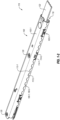
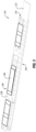
- FIG. 1-1 and FIG. 1-2 illustrate an implementation of a chassis 100 in an open state and a closed state, respectively.
- the chassis 100 is made of a deformable material in a single piece, as described herein.
- the chassis 100 is made of a plastically deformable metal.
- the chassis 100 may be made of a steel alloy.
- the chassis 100 may be a stainless steel alloy.
- the chassis 100 may be an aluminum alloy.
- the chassis 100 may be a titanium alloy.
- the chassis 100 has a first portion 102-1 and a second portion 102-2 that are connected by a hinge 104 positioned between at least part of the first portion 102-1 and the second portion 102-2.
- the hinge 104 connects at least 50% of the axial length (i.e., the direction of the axis of the hinge 104) of the first portion 102-1 and/or second portion 102-2.
- the hinge 104 connects at least 75% of the axial length of the first portion 102-1 and/or second portion 102-2.
- the hinge 104 connects the entire axial length of the first portion 102-1 and/or second portion 102-2.
- the hinge 104 of the chassis 100 is perforated with a plurality of perforations 106.
- the perforations 106 are sized, shaped, and positioned to provide a uniform radius of curvature across the hinge 104 in the closed state.
- a uniform radius of curvature may be a radius of curvature that varies by less than 10% across at least 90% of the area of the hinge 104.
- a uniform radius of curvature may be a radius of curvature that varies by less than 10% across at least 95% of the area of the hinge 104.
- a uniform radius of curvature may be a radius of curvature that varies by less than 10% across the entire area of the hinge 104.
- a uniform radius of curvature may be a radius of curvature that varies by less than 5% across at least 90% of the area of the hinge 104. In yet further examples, a uniform radius of curvature may be a radius of curvature that varies by less than 1% across at least 90% of the area of the hinge 104. In still further examples, a uniform radius of curvature may be a radius of curvature that varies by less than 5% across at least 95% of the area of the hinge 104. In at least one example, it may be critical that a uniform radius of curvature may be a radius of curvature that varies by less than 5% across the entire area of the hinge 104.
- the perforations 106 are sized, shaped, and positioned to provide a uniform surface stress across the hinge 104 in the closed state.
- a uniform surface stress may be a surface stress that varies by less than 10% across at least 90% of the area of the hinge 104.
- a uniform surface stress may be a surface stress that varies by less than 10% across at least 95% of the area of the hinge 104.
- a uniform surface stress may be a surface stress that varies by less than 10% across the entire area of the hinge 104.
- a uniform surface stress may be a surface stress that varies by less than 5% across at least 90% of the area of the hinge 104.
- a uniform surface stress may be a surface stress that varies by less than 1% across at least 90% of the area of the hinge 104. In still further examples, a uniform surface stress may be a surface stress that varies by less than 5% across at least 95% of the area of the hinge 104. In at least one example, a unif uniform surface stress may be a surface stress that varies by less than 5% across the entire area of the hinge 104.
- the perforations 106 are sized, shaped, and positioned to provide a uniform internal stress across the hinge 104 in the closed state.
- a uniform internal stress may be an internal stress that varies by less than 10% across at least 90% of the area of the hinge 104.
- a uniform internal stress may be an internal stress that varies by less than 10% across at least 95% of the area of the hinge 104.
- a uniform internal stress may be an internal stress that varies by less than 10% across the entire area of the hinge 104.
- a uniform internal stress may be an internal stress that varies by less than 5% across at least 90% of the area of the hinge 104.
- a uniform internal stress may be an internal stress that varies by less than 1% across at least 90% of the area of the hinge 104. In still further examples, a uniform internal stress may be an internal stress that varies by less than 5% across at least 95% of the area of the hinge 104. In at least one example, a uniform internal stress may be an internal stress that varies by less than 5% across the entire area of the hinge 104.
- the first portion 102-1 has a first outer edge 108-1 and a first inner edge 110-1.
- the second portion 102-2 has a second outer edge 108-2 and a second inner edge 110-2.
- the hinge 104 connects to the first portion 102-1 along the first inner edge 110-1 and to the second portion 102-2 along the second inner edge 110-2.
- the first outer edge 108-1 and second outer edge 108-2 are configured to contact when in the closed state.
- the first outer edge 108-1 and second outer edge 108-2 have complementary alignment features 112-1, 112-2 and/or complementary connection features 114-1, 114-2.
- the chassis 100 provides strength and durability to an electronic device 116.
- the first portion 102-1 and second portion 102-2 may remain rigid as the hinge 104 deforms to allow the first outer edge 108-1 and second outer edge 108-2 to contact one another.
- a rigid first portion 102-1 and/or second portion 102-2 may deform less than 10% across at least 90% of the area of the first portion 102-1 and/or second portion 102-2.
- a rigid first portion 102-1 and/or second portion 102-2 may deform less than 10% across at least 95% of the area of the first portion 102-1 and/or second portion 102-2.
- a rigid first portion 102-1 and/or second portion 102-2 may deform less than 10% across the entire area of the first portion 102-1 and/or second portion 102-2. In further examples, a rigid first portion 102-1 and/or second portion 102-2 may deform less than 5% across at least 90% of the area of the first portion 102-1 and/or second portion 102-2. In yet further examples, a rigid first portion 102-1 and/or second portion 102-2 may deform less than 5% across at least 95% of the area of the first portion 102-1 and/or second portion 102-2. In at least one example, a rigid first portion 102-1 and/or second portion 102-2 may deform less than 5% across the entire area of the first portion 102-1 and/or second portion 102-2.
- the plurality of complementary connection features 114-1, 114-2 connect and hold the first portion 102-1 in contact with the second portion 102-2.
- the complementary connection features 114-1, 114-2 include or are mechanical connection features that connect and hold by a friction fit, a snap fit, a press fit, a deformable tab and slot, other mechanical connections, or combinations thereof.
- the complementary connection features 114-1, 114-2 include a mechanical fastener such as a pin, rod, bolt, clip, clamp, other mechanical fasteners, or combinations thereof.
- the complementary connection features 114-1, 114-2 include additional connection support, such as welding, brazing, adhesives, or combinations thereof.
- the complementary connection features 114-1, 114-2 may include a slot and tab that snap together, and the slot and tab may be subsequently welded to further support the complementary connection features 114-1, 114-2.
- the plurality of complementary alignment features 112-1, 112-2 engage with one another along at least a portion of the first outer edge 108-1 and second outer edge 108-2 to align the first portion 102-1 and second portion 102-2 in the closed state.
- the complementary alignment features 112-1, 112-2 can limit and/or prevent the movement of the first portion 102-1 and second portion 102-2 relative to one another during use and/or transport of the electronic device.
- the complementary alignment features 112-1, 112-2 may be a series of castellations that engage with one another and to both align and prevent axial movement of the first portion 102-1 and second portion 102-2 relative to one another, such as during three-point bending of the chassis 100.
- the chassis 100 defines an interior space 118 between the first portion 102-1 and second portion 102-2.
- the chassis 100 has a plurality of fasteners 120 that are positioned through at least a portion of the interior space 118 to apply a compressive force and retain the chassis 100 in the closed state.
- the interior space 118 allows the chassis 100 to support and house one or more electronic components, such as a printed circuit board (PCB) 122 including a force sensor that may measure force applied to an end of the electronic device 116.
- PCB printed circuit board
- the chassis thickness 230 is substantially constant through chassis 100. In other implementations, the chassis thickness 230 is smaller in the hinge 204. For example, the chassis thickness 230 may decrease in at least a portion of the hinge 204 to aid in the deformation of the hinge 204 while a greater chassis thickness 230 in other areas of the chassis 200 may promote rigidity. In at least one example, such as a stylus, the chassis thickness 230 may be approximately 0.7 millimeters (mm) throughout the chassis 200. In at least another example, the chassis thickness may be approximately 0.5 mm throughout the hinge 204 and approximately 0.7 mm in the remainder of the chassis 200.
- FIG. 2 illustrates an example of a hinge 204 with a uniform radius of curvature 232.
- a hinge 204 may have some variation across the hinge 204 while still considered uniform.
- the radius of curvature 232 of the hinge 204 is approximately 2.5 mm.
- the hinge 204 therefore, has a 5.0 mm diameter, providing an interior space with a 5.0 mm height.
- the chassis 200 provides the finished outer surface of the electronic device 216.
- an outer sleeve 234 is positioned over at least a portion of the chassis 200 to provide additional housing for electronic components, a different finish, various colorway options, or different surface textures to improve grip during use or transport.
- the outer sleeve 234 may be a polymer that is softer and has a higher coefficient of friction than the chassis 200. The outer sleeve 234 may be more comfortable to hold and use for a user than the chassis 200 itself.
- FIG. 3 is a perspective view of the electronic device 216 of FIG. 2 .
- the electronic device 216 includes a plurality of electronic components positioned at least partially inside the interior space 218 of the chassis 200, such as the PCB 222, and at least one electronic component supported by an outer surface 236 of the chassis 200, such as a communication device 238.
- an electrically conductive chassis 200 forms a gaussian cage around the electronic components in the interior space 218.
- the gaussian cage can reduce electromagnetic interference (EMI) between the electronic components in the interior space 218 and the electronic components supported on the outer surface 236 of the chassis 200.
- a communication device 238 may experience less (EMI) with a chassis 200 according to at least one implementation described herein than some conventional chassis.
- the hinge 204 has a plurality of perforations 206 therein that allow the hinge 204 to deform more easily than the rest of the chassis 200.
- FIG. 4 is a detail view of an implementation of a perforated hinge 304.
- the perforations 306 are sized, shaped, and positioned to provide a uniform radius of curvature, a uniform surface stress, a uniform internal stress, or combinations thereof.
- the perforations 306 illustrated in FIG. 4 are sized, shaped, and positioned to provide struts 340 between the perforations 306 with a strut width 342 that is the same between each perforation 306 along longitudinal axis 344 of the hinge 304.
- the perforations 306 are positioned such that a portion of the perforations 306 overlap in the lateral direction.
- each axial row of perforations 306 overlap the longitudinal axis 344, such that at least a portion of each perforation 306 laterally overlaps a portion of the axially neighboring perforation 306.
- the perforations 306 are polygonal, such as triangles, diamonds, rectangles, squares, pentagons, hexagons, etc. In other implementations, the perforations 306 are round, such as circles, ovals, prolate ovals, or other shapes with continuous perimeters (i.e., no corners). In yet other implementations, the perforations 306 are a combination, such as a rounded polygon.
- the perforations 306 are rounded triangles (i.e., guitar-pick shaped). Rounded triangle perforations 306 yield struts 340 therebetween that are arranged in triangles, providing high strength and low weight.
- the radius of curvature of the rounded corner can be different in different regions of the hinge 304 to account for different forces at different points of the hinge 304.
- the rounded triangle perforations 306 of the implementation in FIG. 4 have a forward point 346 and rearward points 348 with different minimum radii of curvature.
- the forward point 346 has a first minimum radius of curvature 350 that is less than the second minimum radius of curvature 352 of the rearward points 348.
- the perforation 306 has a first minimum radius of curvature 350 of between 0.05 mm and 0.5 mm. In other implementations, the perforation 306 has a first minimum radius of curvature 350 of between 0.1 mm and 0.3 mm. In at least one implementation, the perforation 306 has a first minimum radius of curvature 350 of about 0.2 mm.
- the perforation 306 has a second minimum radius of curvature 352 of between 0.25 mm and 0.75 mm. In other implementations, the perforation 306 has a second minimum radius of curvature 352 of between 0.3 mm and 0.7 mm. In at least one implementation, the perforation 306 has a second minimum radius of curvature 352 of about 0.5 mm.
- FIG. 5 is a flat view of an implementation of a chassis 400 with a hinge 404 having perforations 406 that vary in area, shape, and spacing relative to a longitudinal axis 444 of the hinge 404.
- the perforations 406 may vary according to a lateral distance from the longitudinal axis 444.
- the perforations 406 include at least a center row 454.
- the perforations 406 include at least a center row 454 and secondary rows 456 on either side of the center row 454.
- the perforations 406 include at least a center row 454, secondary rows 456, and tertiary rows 458 on either side of the center row 454.
- the perforations 406 of the center row 454 are the same along the longitudinal axis 444.
- the perforations 406 of the center row 454 may be all the same shape and size, such as illustrated in FIG. 5 .
- the perforations 406 of the center row 454 vary along the longitudinal axis 444.
- the perforations 406 of the center row 454 may alternate between two different shapes and/or different areas along the longitudinal axis 444.
- the perforations 406 of the secondary rows 456 are the same in the direction of the longitudinal axis 444.
- the perforations 406 of the secondary rows 456 may be all the same shape and size, such as illustrated in FIG. 5 .
- the perforations 406 of the secondary rows 456 vary in the direction of the longitudinal axis 444.
- the perforations 406 of the secondary rows 456 may alternate between two different shapes and/or different areas in the direction of the longitudinal axis 444.
- the perforations 406 of the tertiary rows 458 are the same in the direction of the longitudinal axis 444.
- the perforations 406 of the tertiary rows 458 may be all the same shape and size, such as illustrated in FIG. 5 .
- the perforations 406 of the tertiary rows 458 vary in the direction of the longitudinal axis 444.
- the perforations 406 of the tertiary rows 458 may alternate between two different shapes and/or different areas in the direction of the longitudinal axis 444.
- the perforations 406 of the center row 454 and the secondary rows 456 may be the same. In other implementations, the perforations 406 of the center row 454 and the secondary rows 456 may be different. For example, the perforations 406 of the center row 454 in FIG. 5 are oval and have a smaller area than the circular perforations 406 of the secondary rows 456 that flank the center row 454. The secondary rows 456 have perforations that vary in both shape and size from the center row 454.
- the perforations 406 of the tertiary rows 458 may be the same as the center row 454 and/or the secondary rows 456, or the perforations 406 of the tertiary rows 458 may be different from those of both the center row 454 and the secondary rows 456.
- all of the perforations 406 of the center row 454, secondary rows 456, and tertiary rows 458 may be the same.
- the implementation illustrated in FIG. 5 has perforations 406 of the tertiary rows 458 that are of different shape and size from the center row 454 and of different size but the same shape as the secondary rows 456.
- FIG. 6 is a detail view of complementary alignment features 512-1, 512-2 that engage when the chassis in the closed state.
- the first alignment features 512-1 of the first portion 502-1 and/or the second alignment features 512-2 are symmetrical in the axial direction 560.
- each of the first alignment features 512-1 may have a first face 562 and a second face 564 that are oriented at the same angle relative to the axial direction 560.
- a higher angle relative to the axial direction 560 can produce greater resistance to relative movement of the first portion 502-1 and second portion 502-2 in the axial direction 560 (i.e., increasing three-point bending strength of the chassis).
- a lower angle relative to the longitudinal direction can provide more reliable alignment and engagement between the first portion 502-1 and second portion 502-2 during closure of the chassis.
- the first face 562 and/or second face 564 are oriented at an angle relative to the axial direction 560 in a range having an upper value, a lower value, or upper and lower values including any of 20°, 30°, 40°, 45°, 50°, 60°, 70°, 80°, 90°, or any values therebetween.
- the first face 562 and/or second face 564 may be oriented at an angle relative to the axial direction 560 greater than 20°.
- the first face 562 and/or second face 564 may be oriented at an angle relative to the axial direction 560 less than 90°.
- first face 562 and/or second face 564 may be oriented at an angle relative to the axial direction 560 between 20° and 90°. In further examples, the first face 562 and/or second face 564 may be oriented at an angle relative to the axial direction 560 between 30° and 70°. In at least one example, the first face 562 and/or second face 564 may be oriented at an angle relative to the axial direction 560 about 45°. In at least another example, the first face 562 and/or second face 564 may be oriented at an angle relative to the axial direction 560 about 65°.
- the first alignment features 512-1 and/or the second alignment features 512-2 are asymmetrical in the axial direction 560.
- the chassis may experience greater forces applied in a known or expected orientation during use or transport.
- it may be desirable to have a first face 562 oriented at a lower (i.e., shallower) angle relative to the axial direction 560 and a second face 564 oriented at a higher (i.e., steeper) angle relative to the axial direction 560.
- the shallower first face 562 and steeper second face 564, in combination with complementary faces of the second alignment features 512-2 may allow more flex of the chassis in a first direction of torque and provide more rigidity in a second direction of torque on the chassis.
- the first alignment features 512-1 of the first portion 502-1 are the same as the second alignment features 512-2 of the second portion 502-2 with an offset in the axial direction 560.
- the first alignment features 512-1 and the second alignment features 512-2 and/or the spacings therebetween are different.
- the first alignment features 512-1 and the second alignment features 512-2 may be complementary while the first alignment features 512-1 are longer in the axial direction 560 with shorter first recesses 566-2 positioned between the first alignment features 512-1, and the second alignment features 512-2 are shorter in the axial direction 560 (to mate with the first recesses 566-1) with longer second recesses 566-2 (to mate with the first alignment features 512-1).
- a tight fit of the alignment features 512-1, 512-2 with contact along a majority of the surface of the first alignment features 512-1 and the second alignment features 512-2 may allow for greater strength, as well as improved electrical conductivity between the first portion 502-1 and second portion 502-2 of the chassis. Greater electrical conductivity through the chassis and around an interior space may provide a better gaussian cage and increase the EMI shielding of the chassis.
- the first alignment features 512-1 and/or the second alignment features 512-2 have gaps 568 at the corners.
- the corners of the first alignment features 512-1 and/or the second alignment features 512-2 may be rounded, while the corners of the first recesses 566-1 and second recesses 566-2 are angular, resulting in gaps 568 between the first alignment features 512-1 and the second alignment features 512-2 when the chassis is in the closed state.
- the gaps 568 can provide tolerances for machining or manufacturing accuracy.
- the gaps 568 can allow the majority of the edges of the first alignment features 512-1 and the second alignment features 512-2 to contact, even if debris or flash remains on the edges.
- the gaps 568 can allow improved contact between the first alignment features 512-1 and/or the second alignment features 512-2, such that the chassis can provide EMI shielding without a bridging conductive element, such as copper tape, connecting the first portion 502-1 to the second portion 502-2.
- FIG. 7 is a flowchart illustrating an implementation of a method 670 of manufacturing an electronic device.
- the method 670 includes forming a chassis from a single piece of deformable material at 672.
- the single piece of material is additively manufactured by bonding a plurality of pieces together to form the chassis.
- the chassis may be formed by bonding a metal powder through laser melting or laser sintering.
- a plurality of pieces may be integrally bonded by welding to form a single continuous piece of material.
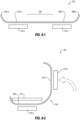
- FIG. 8-1 through FIG. 8-3 illustrate the folding of a chassis.
- FIG. 8-1 is an end view of a chassis 700 positioned on a press having a first plate 778-1 and a second plate 778-2.
- the first plate 788-1 and second plate 788-2 are movable relative to one another to fold the first portion 702-1 of the chassis 700 toward the second portion 702-2 around the sheet metal bend that will form the hinge 704.
- the hinge 704 deforms with a controlled radius of curvature such that the first outer edge 708-1 moves toward the second outer edge 708-2.
- FIG. 8-2 is an end side view of the chassis 700 and plates 778-1, 778-2 of FIG. 8-1 midway through folding the chassis 700.
- An electronic component such as a PCB 722 is positioned on an inner surface 780 of the chassis 700 as the first portion 702-1 is folded over the second portion 702-2 by the first plate 788-1 and second plate 788-2 moving relative to one another.
- Folding the chassis 700 allows for electronic components to be positioned in the chassis even if the electronic component is too large to be inserted axially into the chassis 700 in the closed state.
- a plurality of electronic components can be placed on the inner surface 780 and arranged such that the electronic components at least partially support one another when the chassis 700 is closed.
- Numbers, percentages, ratios, or other values stated herein are intended to include that value, and also other values that are “about” or “approximately” the stated value, as would be appreciated by one of ordinary skill in the art encompassed by implementations of the present disclosure.
- a stated value should therefore be interpreted broadly enough to encompass values that are at least close enough to the stated value to perform a desired function or achieve a desired result.
- the stated values include at least the variation to be expected in a suitable manufacturing or production process, and may include values that are within 5%, within 1%, within 0.1%, or within 0.01% of a stated value.
- any references to “up” and “down” or “above” or “below” are merely descriptive of the relative position or movement of the related elements.
Landscapes
- Engineering & Computer Science (AREA)
- General Engineering & Computer Science (AREA)
- Theoretical Computer Science (AREA)
- Physics & Mathematics (AREA)
- General Physics & Mathematics (AREA)
- Microelectronics & Electronic Packaging (AREA)
- Human Computer Interaction (AREA)
- Casings For Electric Apparatus (AREA)
Claims (15)
- Chassis (100) für ein elektronisches Gerät, wobei das Chassis einen offenen Zustand und einen geschlossenen Zustand aufweist und das Chassis eine Chassishöhe aufweist, wobei das Chassis Folgendes beinhaltet:einen ersten Abschnitt (102-1), der eine erste Außenkante (108-1) und eine erste Innenkante (110-1) aufweist;einen zweiten Abschnitt (102-2), der eine zweite Außenkante (108-2) und eine zweite Innenkante (110-2) aufweist; undein perforiertes Scharnier (104), das eine Vielzahl von Perforationen (106) beinhaltet, wobei das perforierte Scharnier (104) zwischen dem ersten Abschnitt (102-1) und dem zweiten Abschnitt (102-2) an der ersten Innenkante (110-1) und der zweiten Innenkante (110-2) positioniert ist, wobei der erste Abschnitt, der zweite Abschnitt und das perforierte Scharnier (104) in einem Stück aus einem durchgehenden Stück geformt sind und das perforierte Scharnier (104) so konfiguriert ist, dass es sich verformt, während sich das Chassis vom offenen Zustand in den geschlossenen Zustand bewegt, um die erste Außenkante (108-1) mit der zweiten Außenkante (108-2) im geschlossenen Zustand passend zusammenzufügen;wobei das Chassis (100) im geschlossenen Zustand einen Innenraum (118) zwischen dem ersten Abschnitt (102-1) und dem zweiten Abschnitt (102-2) definiert, wobei der Innenraum mindestens ein elektronisches Bauteil enthält;wobei das perforierte Scharnier im geschlossenen Zustand eine abgerundete Form im Profil um dessen Längsachse (244, 344) und einen kontrollierten Krümmungsradius aufweist und eine Scharnierhöhe im geschlossenen Zustand die Chassishöhe definiert.
- Chassis nach Anspruch 1, wobei das perforierte Scharnier eine erste axiale Reihe von Perforationen und eine zweite axiale Reihe von Perforationen aufweist, wobei die erste axiale Reihe und die zweite axiale Reihe sich in einer seitlichen Richtung zumindest teilweise überlappen.
- Chassis nach Anspruch 1, wobei die Vielzahl von Perforationen (106) gemäß einem oder mehreren der folgenden Merkmale angeordnet ist:(i) die Vielzahl von Perforationen (106) ist wie ein Gitarrenplektrum geformt;(ii) die Vielzahl von Perforationen (106) ist polygonal;(iii) die Vielzahl von Perforationen (106) variiert in der Form;(iv) die Vielzahl von Perforationen (106) variiert in der Fläche.
- Chassis nach Anspruch 1, wobei ein Großteil des perforierten Scharniers (104) im geschlossenen Zustand um eine Längsachse des perforierten Scharniers einen gleichmäßigen Krümmungsradius aufweist.
- Chassis nach Anspruch 1, wobei die Vielzahl von Perforationen (106) des perforierten Scharniers (104) so bemessen, geformt und positioniert ist, dass sie im geschlossenen Zustand eine gleichmäßige Oberflächenspannung bereitstellt.
- Chassis nach Anspruch 1, wobei die Vielzahl von Perforationen (106) des perforierten Scharniers (104) so bemessen, geformt und positioniert ist, dass sie im geschlossenen Zustand eine gleichmäßige innere Spannung bereitstellt.
- Chassis nach Anspruch 1, wobei die erste Außenkante (108-1) und die zweite Außenkante (108-2) komplementäre Verbindungsmerkmale aufweisen.
- Chassis nach Anspruch 1, wobei das Chassis (100) im geschlossenen Zustand eine Ausdehnungskraft von weniger als 5 Newton aufbringt.
- Chassis nach Anspruch 1, wobei die Vielzahl von Perforationen (106) so konfiguriert ist, dass sich das Scharnier (104) leichter als der Rest des Chassis verformen kann.
- Chassis nach Anspruch 6, wobei das perforierte Scharnier so konfiguriert ist, dass die innere Spannung über mindestens 90 % der Fläche des perforierten Scharniers (104) um weniger als 10 % variiert.
- Chassis nach Anspruch 5, wobei das perforierte Scharnier (104) so konfiguriert ist, dass die Oberflächenspannung über mindestens 90 % der Fläche des perforierten Scharniers um weniger als 10 % variiert.
- Stift (116), umfassend ein Chassis nach Anspruch 1,wobei die erste Außenkante (108-1) und die zweite Außenkante (108-2) in dem geschlossenen Zustand miteinander verbunden sind;der Stift ferner umfasst:einen von dem Chassis (100, 200) getragenen Kraftsensor; undein von dem Chassis getragenes Kommunikationsgerät (238).
- Stift nach Anspruch 12, wobei das Kommunikationsgerät außerhalb des Innenraums (218) des Chassis positioniert ist.
- Stift nach Anspruch 12, ferner umfassend eine von dem Chassis im Innenraum (218) des Chassis getragene Batterie.
- Stift nach Anspruch 12, wobei das Chassis (200) elektrisch leitend ist und einen Gauß'schen Käfig bildet.
Applications Claiming Priority (2)
| Application Number | Priority Date | Filing Date | Title |
|---|---|---|---|
| US16/224,753 US10765024B2 (en) | 2018-12-18 | 2018-12-18 | Hinged chassis with a uniform stress hinge |
| PCT/US2019/064337 WO2020131363A1 (en) | 2018-12-18 | 2019-12-04 | Hinged chassis with a uniform stress hinge |
Publications (2)
| Publication Number | Publication Date |
|---|---|
| EP3874355A1 EP3874355A1 (de) | 2021-09-08 |
| EP3874355B1 true EP3874355B1 (de) | 2025-03-19 |
Family
ID=69024641
Family Applications (1)
| Application Number | Title | Priority Date | Filing Date |
|---|---|---|---|
| EP19828414.3A Active EP3874355B1 (de) | 2018-12-18 | 2019-12-04 | Gelenkchassis mit einem gleichmässigen spannungsscharnier |
Country Status (4)
| Country | Link |
|---|---|
| US (1) | US10765024B2 (de) |
| EP (1) | EP3874355B1 (de) |
| CN (1) | CN113196214B (de) |
| WO (1) | WO2020131363A1 (de) |
Family Cites Families (27)
| Publication number | Priority date | Publication date | Assignee | Title |
|---|---|---|---|---|
| US3183302A (en) * | 1962-01-08 | 1965-05-11 | Jasper Blackburn Corp | Cover for an electrical connector |
| US3846725A (en) * | 1973-04-30 | 1974-11-05 | Gen Instrument Corp | Coil retainer |
| US5191172A (en) * | 1991-11-07 | 1993-03-02 | Garganese Richard S | Cable terminal protector |
| US5434362A (en) | 1994-09-06 | 1995-07-18 | Motorola, Inc. | Flexible circuit board assembly and method |
| US5614694A (en) | 1995-03-31 | 1997-03-25 | Motorola, Inc. | One piece open and closable metal RF shield |
| JP3081775B2 (ja) * | 1995-05-29 | 2000-08-28 | 矢崎総業株式会社 | 防水保護カバー |
| US6359228B1 (en) | 2000-01-31 | 2002-03-19 | Corning Cable Systems Llc | Splice closure |
| US6685022B2 (en) | 2002-01-29 | 2004-02-03 | International Paper Company | Clam shell container with cover and inner tray |
| KR100461295B1 (ko) * | 2002-06-22 | 2004-12-14 | 삼성전자주식회사 | 디스크 플레이어의 진동저감장치 |
| US6897371B1 (en) | 2002-08-27 | 2005-05-24 | A K Stamping Co. Inc. | One-piece shielding enclosure with selective interior access, and method and blank therefor |
| CA2542929C (en) * | 2003-07-30 | 2012-04-10 | Prysmian Cables & Systems Limited | Improvements relating to cable installation |
| US8412017B2 (en) * | 2009-05-13 | 2013-04-02 | Adc Telecommunications, Inc. | Cable pulling assembly |
| US9518768B2 (en) | 2009-06-10 | 2016-12-13 | Mahle International Gmbh | Evaporator having a phase change material louvered clam shell housing |
| US8022327B2 (en) | 2009-06-19 | 2011-09-20 | Michael Blomeyer | Switch, circuitry, and method of assembly for electrosurgical pencil |
| US20120267266A1 (en) * | 2011-04-19 | 2012-10-25 | Richard Hunter | Multi-media storage and business card blank |
| US8797301B2 (en) | 2012-02-15 | 2014-08-05 | Cypress Semiconductor Corporation | Active stylus to host data transmitting method |
| US8959877B2 (en) * | 2012-05-24 | 2015-02-24 | The Quaker Oats Company | Food packaging carton and method of making packaging carton |
| TR201905245T4 (tr) * | 2013-04-25 | 2019-05-21 | Weidmueller Interface Gmbh & Co Kg | Kablo işaretleyici. |
| KR102039496B1 (ko) * | 2013-08-19 | 2019-11-04 | 삼성디스플레이 주식회사 | 접이식 표시 장치 |
| TW201530365A (zh) | 2014-01-29 | 2015-08-01 | Waltop Int Corp | 能提供可調變電磁場的主動式電容觸控筆 |
| US20150373867A1 (en) | 2014-06-18 | 2015-12-24 | Continental Automotive Systems, Inc. | Electronics housing |
| US9721703B2 (en) * | 2015-05-27 | 2017-08-01 | Te Connectivity Corporation | Wildlife guard apparatus, modular systems and methods for using the same |
| TWM517858U (zh) | 2015-09-16 | 2016-02-21 | Waltop Int Corp | 可攜式電子裝置及其小型化充電式電容觸控筆 |
| US10185409B2 (en) * | 2016-03-15 | 2019-01-22 | Microsoft Technology Licensing, Llc | Stylus with an adjustable dimension |
| KR102578589B1 (ko) * | 2016-09-30 | 2023-09-14 | 엘지디스플레이 주식회사 | 플렉서블 표시장치 |
| KR102611993B1 (ko) * | 2016-10-12 | 2023-12-08 | 삼성디스플레이 주식회사 | 플렉시블 표시 장치 |
| DK3225390T3 (en) * | 2017-02-09 | 2019-03-18 | Eastwest Int Taiwan Enterprises | PROCEDURE FOR PREPARING A HORSE PROTECTION COVER |
-
2018
- 2018-12-18 US US16/224,753 patent/US10765024B2/en active Active
-
2019
- 2019-12-04 WO PCT/US2019/064337 patent/WO2020131363A1/en not_active Ceased
- 2019-12-04 EP EP19828414.3A patent/EP3874355B1/de active Active
- 2019-12-04 CN CN201980084646.3A patent/CN113196214B/zh active Active
Also Published As
| Publication number | Publication date |
|---|---|
| EP3874355A1 (de) | 2021-09-08 |
| CN113196214B (zh) | 2024-11-05 |
| US20200196468A1 (en) | 2020-06-18 |
| US10765024B2 (en) | 2020-09-01 |
| WO2020131363A1 (en) | 2020-06-25 |
| CN113196214A (zh) | 2021-07-30 |
Similar Documents
| Publication | Publication Date | Title |
|---|---|---|
| EP3644390B1 (de) | Vorrichtung und verfahren zur herstellung eines beutels und verfahren zur herstellung einer sekundärbatterie | |
| EP2985805B1 (de) | Gekrümmte-batterie und verfahren zur herstellung davon | |
| TWI497798B (zh) | 電池殼體用蓋及電池殼體用蓋之製造方法 | |
| TWI619291B (zh) | Battery case | |
| EP3344022B1 (de) | Elektronische vorrichtung mit metallgehäuse und metallgehäuse zur verwendung dafür | |
| EP2744013B1 (de) | Abdeckkörper für batteriegehäuse | |
| EP3252849A1 (de) | Kappenanordnung | |
| KR101861907B1 (ko) | 전지 케이스용의 덮개체 | |
| WO2019089797A1 (en) | Battery pack protection circuit module | |
| WO2020131363A1 (en) | Hinged chassis with a uniform stress hinge | |
| EP2999023B1 (de) | Sekundärbatterie | |
| JPWO2008133276A1 (ja) | 電子光学機器製品用外装ケースおよび製造方法 | |
| KR20200098172A (ko) | 다이유닛, 그의 제조방법 및 파우치 성형장치 | |
| CN111049963A (zh) | 壳体及其制备方法 | |
| EP3739649B1 (de) | Sekundärbatteriegehäuse, sekundärbatterie und batteriemodul | |
| JP5675864B2 (ja) | 電池の安全弁製造方法及び製造装置 | |
| CN114730945B (zh) | 二次电池及制造二次电池的方法 | |
| EP3905427B1 (de) | Gehäuse für sekundärbatterie und sekundärbatterie | |
| CN114497916B (zh) | 极耳、电化学装置、用电设备及压辊 | |
| KR20220008773A (ko) | 전극 커팅장치 및 커팅방법, 그를 포함하는 전극 제조설비 | |
| JP6098188B2 (ja) | パイプ体、パイプ体製造方法 | |
| EP3308873B1 (de) | Verfahren zur herstellung einer unterlegscheibe | |
| CN212542619U (zh) | 一种贴装防呆的l形镍片 | |
| CN104588454B (zh) | 一种家装板材的生产工艺 | |
| CN114877071B (zh) | 一种带触指片的指尖密封结构及其加工方法 |
Legal Events
| Date | Code | Title | Description |
|---|---|---|---|
| STAA | Information on the status of an ep patent application or granted ep patent |
Free format text: STATUS: UNKNOWN |
|
| STAA | Information on the status of an ep patent application or granted ep patent |
Free format text: STATUS: THE INTERNATIONAL PUBLICATION HAS BEEN MADE |
|
| PUAI | Public reference made under article 153(3) epc to a published international application that has entered the european phase |
Free format text: ORIGINAL CODE: 0009012 |
|
| STAA | Information on the status of an ep patent application or granted ep patent |
Free format text: STATUS: REQUEST FOR EXAMINATION WAS MADE |
|
| 17P | Request for examination filed |
Effective date: 20210601 |
|
| AK | Designated contracting states |
Kind code of ref document: A1 Designated state(s): AL AT BE BG CH CY CZ DE DK EE ES FI FR GB GR HR HU IE IS IT LI LT LU LV MC MK MT NL NO PL PT RO RS SE SI SK SM TR |
|
| RAP3 | Party data changed (applicant data changed or rights of an application transferred) |
Owner name: MICROSOFT TECHNOLOGY LICENSING, LLC |
|
| RAP3 | Party data changed (applicant data changed or rights of an application transferred) |
Owner name: MICROSOFT TECHNOLOGY LICENSING, LLC |
|
| DAV | Request for validation of the european patent (deleted) | ||
| DAX | Request for extension of the european patent (deleted) | ||
| STAA | Information on the status of an ep patent application or granted ep patent |
Free format text: STATUS: EXAMINATION IS IN PROGRESS |
|
| 17Q | First examination report despatched |
Effective date: 20220512 |
|
| GRAP | Despatch of communication of intention to grant a patent |
Free format text: ORIGINAL CODE: EPIDOSNIGR1 |
|
| STAA | Information on the status of an ep patent application or granted ep patent |
Free format text: STATUS: GRANT OF PATENT IS INTENDED |
|
| INTG | Intention to grant announced |
Effective date: 20241028 |
|
| GRAS | Grant fee paid |
Free format text: ORIGINAL CODE: EPIDOSNIGR3 |
|
| GRAA | (expected) grant |
Free format text: ORIGINAL CODE: 0009210 |
|
| STAA | Information on the status of an ep patent application or granted ep patent |
Free format text: STATUS: THE PATENT HAS BEEN GRANTED |
|
| P01 | Opt-out of the competence of the unified patent court (upc) registered |
Free format text: CASE NUMBER: APP_5801/2025 Effective date: 20250204 |
|
| AK | Designated contracting states |
Kind code of ref document: B1 Designated state(s): AL AT BE BG CH CY CZ DE DK EE ES FI FR GB GR HR HU IE IS IT LI LT LU LV MC MK MT NL NO PL PT RO RS SE SI SK SM TR |
|
| REG | Reference to a national code |
Ref country code: GB Ref legal event code: FG4D |
|
| REG | Reference to a national code |
Ref country code: CH Ref legal event code: EP |
|
| REG | Reference to a national code |
Ref country code: DE Ref legal event code: R096 Ref document number: 602019067552 Country of ref document: DE |
|
| REG | Reference to a national code |
Ref country code: IE Ref legal event code: FG4D |
|
| PG25 | Lapsed in a contracting state [announced via postgrant information from national office to epo] |
Ref country code: RS Free format text: LAPSE BECAUSE OF FAILURE TO SUBMIT A TRANSLATION OF THE DESCRIPTION OR TO PAY THE FEE WITHIN THE PRESCRIBED TIME-LIMIT Effective date: 20250619 |
|
| PG25 | Lapsed in a contracting state [announced via postgrant information from national office to epo] |
Ref country code: FI Free format text: LAPSE BECAUSE OF FAILURE TO SUBMIT A TRANSLATION OF THE DESCRIPTION OR TO PAY THE FEE WITHIN THE PRESCRIBED TIME-LIMIT Effective date: 20250319 |
|
| REG | Reference to a national code |
Ref country code: LT Ref legal event code: MG9D |
|
| PG25 | Lapsed in a contracting state [announced via postgrant information from national office to epo] |
Ref country code: NO Free format text: LAPSE BECAUSE OF FAILURE TO SUBMIT A TRANSLATION OF THE DESCRIPTION OR TO PAY THE FEE WITHIN THE PRESCRIBED TIME-LIMIT Effective date: 20250619 |
|
| PG25 | Lapsed in a contracting state [announced via postgrant information from national office to epo] |
Ref country code: HR Free format text: LAPSE BECAUSE OF FAILURE TO SUBMIT A TRANSLATION OF THE DESCRIPTION OR TO PAY THE FEE WITHIN THE PRESCRIBED TIME-LIMIT Effective date: 20250319 |
|
| PG25 | Lapsed in a contracting state [announced via postgrant information from national office to epo] |
Ref country code: LV Free format text: LAPSE BECAUSE OF FAILURE TO SUBMIT A TRANSLATION OF THE DESCRIPTION OR TO PAY THE FEE WITHIN THE PRESCRIBED TIME-LIMIT Effective date: 20250319 |
|
| PG25 | Lapsed in a contracting state [announced via postgrant information from national office to epo] |
Ref country code: GR Free format text: LAPSE BECAUSE OF FAILURE TO SUBMIT A TRANSLATION OF THE DESCRIPTION OR TO PAY THE FEE WITHIN THE PRESCRIBED TIME-LIMIT Effective date: 20250620 Ref country code: BG Free format text: LAPSE BECAUSE OF FAILURE TO SUBMIT A TRANSLATION OF THE DESCRIPTION OR TO PAY THE FEE WITHIN THE PRESCRIBED TIME-LIMIT Effective date: 20250319 |
|
| REG | Reference to a national code |
Ref country code: NL Ref legal event code: MP Effective date: 20250319 |
|
| REG | Reference to a national code |
Ref country code: AT Ref legal event code: MK05 Ref document number: 1777472 Country of ref document: AT Kind code of ref document: T Effective date: 20250319 |
|
| PG25 | Lapsed in a contracting state [announced via postgrant information from national office to epo] |
Ref country code: NL Free format text: LAPSE BECAUSE OF FAILURE TO SUBMIT A TRANSLATION OF THE DESCRIPTION OR TO PAY THE FEE WITHIN THE PRESCRIBED TIME-LIMIT Effective date: 20250319 |
|
| PG25 | Lapsed in a contracting state [announced via postgrant information from national office to epo] |
Ref country code: SE Free format text: LAPSE BECAUSE OF FAILURE TO SUBMIT A TRANSLATION OF THE DESCRIPTION OR TO PAY THE FEE WITHIN THE PRESCRIBED TIME-LIMIT Effective date: 20250319 |
|
| PG25 | Lapsed in a contracting state [announced via postgrant information from national office to epo] |
Ref country code: SM Free format text: LAPSE BECAUSE OF FAILURE TO SUBMIT A TRANSLATION OF THE DESCRIPTION OR TO PAY THE FEE WITHIN THE PRESCRIBED TIME-LIMIT Effective date: 20250319 |
|
| PG25 | Lapsed in a contracting state [announced via postgrant information from national office to epo] |
Ref country code: PT Free format text: LAPSE BECAUSE OF FAILURE TO SUBMIT A TRANSLATION OF THE DESCRIPTION OR TO PAY THE FEE WITHIN THE PRESCRIBED TIME-LIMIT Effective date: 20250721 Ref country code: ES Free format text: LAPSE BECAUSE OF FAILURE TO SUBMIT A TRANSLATION OF THE DESCRIPTION OR TO PAY THE FEE WITHIN THE PRESCRIBED TIME-LIMIT Effective date: 20250319 |
|
| PG25 | Lapsed in a contracting state [announced via postgrant information from national office to epo] |
Ref country code: PL Free format text: LAPSE BECAUSE OF FAILURE TO SUBMIT A TRANSLATION OF THE DESCRIPTION OR TO PAY THE FEE WITHIN THE PRESCRIBED TIME-LIMIT Effective date: 20250319 Ref country code: IT Free format text: LAPSE BECAUSE OF FAILURE TO SUBMIT A TRANSLATION OF THE DESCRIPTION OR TO PAY THE FEE WITHIN THE PRESCRIBED TIME-LIMIT Effective date: 20250319 |
|
| PG25 | Lapsed in a contracting state [announced via postgrant information from national office to epo] |
Ref country code: AT Free format text: LAPSE BECAUSE OF FAILURE TO SUBMIT A TRANSLATION OF THE DESCRIPTION OR TO PAY THE FEE WITHIN THE PRESCRIBED TIME-LIMIT Effective date: 20250319 |
|
| PG25 | Lapsed in a contracting state [announced via postgrant information from national office to epo] |
Ref country code: CZ Free format text: LAPSE BECAUSE OF FAILURE TO SUBMIT A TRANSLATION OF THE DESCRIPTION OR TO PAY THE FEE WITHIN THE PRESCRIBED TIME-LIMIT Effective date: 20250319 Ref country code: EE Free format text: LAPSE BECAUSE OF FAILURE TO SUBMIT A TRANSLATION OF THE DESCRIPTION OR TO PAY THE FEE WITHIN THE PRESCRIBED TIME-LIMIT Effective date: 20250319 |
|
| PG25 | Lapsed in a contracting state [announced via postgrant information from national office to epo] |
Ref country code: RO Free format text: LAPSE BECAUSE OF FAILURE TO SUBMIT A TRANSLATION OF THE DESCRIPTION OR TO PAY THE FEE WITHIN THE PRESCRIBED TIME-LIMIT Effective date: 20250319 |
|
| PG25 | Lapsed in a contracting state [announced via postgrant information from national office to epo] |
Ref country code: SK Free format text: LAPSE BECAUSE OF FAILURE TO SUBMIT A TRANSLATION OF THE DESCRIPTION OR TO PAY THE FEE WITHIN THE PRESCRIBED TIME-LIMIT Effective date: 20250319 |
|
| PG25 | Lapsed in a contracting state [announced via postgrant information from national office to epo] |
Ref country code: IS Free format text: LAPSE BECAUSE OF FAILURE TO SUBMIT A TRANSLATION OF THE DESCRIPTION OR TO PAY THE FEE WITHIN THE PRESCRIBED TIME-LIMIT Effective date: 20250719 |
|
| REG | Reference to a national code |
Ref country code: DE Ref legal event code: R097 Ref document number: 602019067552 Country of ref document: DE |
|
| PGFP | Annual fee paid to national office [announced via postgrant information from national office to epo] |
Ref country code: DE Payment date: 20251126 Year of fee payment: 7 |
|
| PGFP | Annual fee paid to national office [announced via postgrant information from national office to epo] |
Ref country code: GB Payment date: 20251120 Year of fee payment: 7 |
|
| PG25 | Lapsed in a contracting state [announced via postgrant information from national office to epo] |
Ref country code: DK Free format text: LAPSE BECAUSE OF FAILURE TO SUBMIT A TRANSLATION OF THE DESCRIPTION OR TO PAY THE FEE WITHIN THE PRESCRIBED TIME-LIMIT Effective date: 20250319 |
|
| PLBE | No opposition filed within time limit |
Free format text: ORIGINAL CODE: 0009261 |
|
| STAA | Information on the status of an ep patent application or granted ep patent |
Free format text: STATUS: NO OPPOSITION FILED WITHIN TIME LIMIT |
|
| REG | Reference to a national code |
Ref country code: CH Ref legal event code: L10 Free format text: ST27 STATUS EVENT CODE: U-0-0-L10-L00 (AS PROVIDED BY THE NATIONAL OFFICE) Effective date: 20260128 |
|
| 26N | No opposition filed |
Effective date: 20251222 |