EP3874103B1 - Barriereanordnung - Google Patents
Barriereanordnung Download PDFInfo
- Publication number
- EP3874103B1 EP3874103B1 EP19831857.8A EP19831857A EP3874103B1 EP 3874103 B1 EP3874103 B1 EP 3874103B1 EP 19831857 A EP19831857 A EP 19831857A EP 3874103 B1 EP3874103 B1 EP 3874103B1
- Authority
- EP
- European Patent Office
- Prior art keywords
- barrier
- barrier assembly
- adaptor
- assembly according
- fence post
- Prior art date
- Legal status (The legal status is an assumption and is not a legal conclusion. Google has not performed a legal analysis and makes no representation as to the accuracy of the status listed.)
- Active
Links
Images


Classifications
-
- E—FIXED CONSTRUCTIONS
- E04—BUILDING
- E04H—BUILDINGS OR LIKE STRUCTURES FOR PARTICULAR PURPOSES; SWIMMING OR SPLASH BATHS OR POOLS; MASTS; FENCING; TENTS OR CANOPIES, IN GENERAL
- E04H17/00—Fencing, e.g. fences, enclosures, corrals
- E04H17/003—Anti-climbing devices, e.g. fixed spikes
-
- A—HUMAN NECESSITIES
- A01—AGRICULTURE; FORESTRY; ANIMAL HUSBANDRY; HUNTING; TRAPPING; FISHING
- A01G—HORTICULTURE; CULTIVATION OF VEGETABLES, FLOWERS, RICE, FRUIT, VINES, HOPS OR SEAWEED; FORESTRY; WATERING
- A01G13/00—Protection of plants
- A01G13/10—Devices for affording protection against animals, birds or other pests
- A01G13/105—Protective devices against slugs, snails, crawling insects or other climbing animals
-
- E—FIXED CONSTRUCTIONS
- E04—BUILDING
- E04H—BUILDINGS OR LIKE STRUCTURES FOR PARTICULAR PURPOSES; SWIMMING OR SPLASH BATHS OR POOLS; MASTS; FENCING; TENTS OR CANOPIES, IN GENERAL
- E04H17/00—Fencing, e.g. fences, enclosures, corrals
- E04H17/14—Fences constructed of rigid elements, e.g. with additional wire fillings or with posts
- E04H17/24—Connections for attaching additional wire to frames, posts or railings
Definitions
- This invention concerns improvements in or relating to barrier assemblies, and also kits of parts for forming barrier assemblies.
- bracket assemblies are often required at the top of a closure such as a fence or wall to prevent animals or people climbing over the closure.
- Conventionally inclined brackets are used, which brackets include a first part engageable against the closure, and an inclined part extending therefrom which will generally extend upwardly and inwardly.
- a further top part at a greater inclination to the closure may extend at least generally perpendicularly to the closure.
- brackets Conventionally mesh, netting, wires or other barrier materials may be provided extending between the brackets.
- Existing arrangements often require a number of different brackets usable in different situations. For instance inclined brackets may be required for use in corners where the bracket inclined part will usually be required to extend at an inclination in a required direction of around 45° to the first part. Also longer brackets may be needed for instance for lower height closures.
- US 1 980 852 A relates to improvements in fence post extension arms.
- a barrier assembly comprising a bracket member which comprises a first mounting part and a second barrier part extending in use at a vertical inclination relative thereto, the assembly also including an alignment adaptor mountable to a surface of a closure member, with the bracket member mountable to the alignment adaptor, such that the mounting part is inclined relative to the closure member surface, about a vertical axis.
- the alignment adaptor may include a first formation mountable to the surface of a closure member, and a second formation to which a bracket member is mountable.
- the first formation may include a plurality of through holes through which a fastening means can extend.
- the second formation may include an engagement face against which a barrier member can engage, which engagement face will be inclined relative to the surface of a closure member to which the alignment adaptor is mounted.
- the engagement face may extend at substantially 45° to the surface of a closure member to which the alignment adaptor is mounted.
- the engagement face may be configured such that it can be inclined in either direction relative to the surface of a closure, and may be movable between inclinations in either direction by rotating through 180°.
- the second formation may include a plurality of holes, which may be threaded.
- the alignment adaptor is in the form of a hollow body which is at least generally triangular in plan view.
- the hollow body may be made of a plastics material.
- the alignment adaptor may have a generally L shaped configuration.
- the connection between the limbs of the L may be inclined, and the second formation may be provided in the inclined connection.
- a bracket member comprising a first mounting part, and a second barrier part extending at a vertical inclination relative thereto, the assembly also including an extension member, which extension member is mountable on a closure member, with a bracket member mountable to the extension member so as to extend higher than if the bracket member was mounted directly to the closure member.
- Third mounting formations may be provided on the extension member to enable mounting of the extension member to a closure, and the third mounting formations may comprise a plurality of spaced holes.
- a base formation may be provided on the extension member to receive the lower end of a bracket member mounted thereto.
- the extension member may have a base part locatable against a closure member, with side walls extending from the base part such that a bracket member can slidingly locate between the side walls.
- the side walls may taper outwardly in an upwards direction. Inward projections may be provided on the side walls to retain a bracket member therebetween.
- a bracket member comprising a first mounting part, and a second barrier part extending in use at a vertical inclination relative thereto, the bracket member having a generally channel section profile with a base and side walls.
- the side walls may taper outwardly on the mounting part towards the barrier part.
- the side walls may taper inwardly on the barrier part away from the mounting part.
- the bracket member may also include a third part extending from the barrier part at a greater inclination to the mounting part.
- the side walls of the third part may taper inwardly away from the barrier.
- a plurality of adjacent through holes may be provided in the base and side walls of the barrier part, to permit mounting of items to the bracket member. Adjacent through holes may also be provided in the third part of the barrier member.
- the base of the bracket member channel section may be profiled and may have a raised central section which may extend for the majority of the width of the channel section.
- the side walls of the channel section may be inclined outwardly.
- the bracket members may be made of metal and for instance steel, and may be made by stamping or pressing.
- the extension members may be made of metal and for instance steel, and may be made by stamping or pressing.
- a first kit of parts for forming a barrier assembly including a plurality of bracket members and alignment adaptors according to any of the preceding paragraphs.
- kit of parts for forming a barrier assembly, the kit of parts including a plurality of bracket members and extension members according to any of the preceding paragraphs.
- the second kit of parts may also include a plurality of alignment adaptors.
- the invention further provides a barrier assembly including a plurality of bracket members according to any of the preceding paragraphs, with barrier means extending between the bracket members.
- the barrier assembly may also include one or more extension members.
- the barrier assembly may also include one or more alignment adaptors.
- the drawings show various barrier assemblies and components used therein to provide an overhanging barrier arrangement.
- the assembly in particular comprises one or more of bracket members ( Fig. 1 ), an alignment adaptor ( Fig. 8 ) and/or an extension member ( Fig. 16 ).
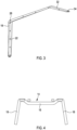
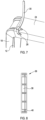
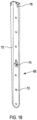
- Fig. 1 shows a bracket 10 member comprises a first mounting part 12 formed of a generally channel cross section as shown in Fig. 4 , with a base 14 with an upper raised part 16 and side walls 18 which diverge gently outwardly.
- the side walls 18 increase in height away from their lower end 20 in use.
- a plurality of spaced mounting holes 22 are provided in the base 14 of the mounting part 12.
- the mounting part 12 connects to a barrier part 24 which is inclined relative to the mounting part to provide an overhang in use.
- the side walls 18 reduce gently in height in the barrier part 24 away from the mounting part 12.
- a plurality of spaced pairs 26 of adjacent fixing holes 28 are provided respectively in the base 14 of the channel of the barrier part, and adjacent in respective side wall 18 for mounting a cable tie 30 as shown for example in Fig. 7 , to mount an item or material to the bracket member 10.
- the pairs 26 of fixing holes are provided alternately on opposite sides of the barrier part 24.
- a further top part 32 extends from the free end of the barrier part 24 and again the height of the side walls 18 decreases gently along the top part 32, and a pair 26 of adjacent fixing holes are provided on each side, with a final mounting hole 34 at the end of the top part 32.
- the bracket members 10 may be formed by stamping or pressing of galvanised steel.
- the formation of the base 14 of the channel has been found to provide significant additional strength relative to a non profiled channel, which therefore permits thinner material to be used whilst obtaining equal or enhanced performance. This therefore provides a weight and cost reduction.
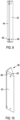
- Figs. 8 to 11 show a first alignment adaptor 36 which is in the form of a profiled open body of a glass filled plastics material made for instance by injection moulding.
- the alignment adaptor 36 provides an open surface 38 engageable against a fence post 40 or the like.
- the adaptor 36 also provides a flat engagement face 42 inclined at substantially 45° to the open surface 38.
- a gently curved face 44 extends between the open surface 38 and engagement face 42.
- a pair of mounting holes 46 are provided in the junction between the engagement face 42 and curved face 44, to permit mounting of the adaptor 36 to a fence post 40 or similar.
- a further pair of holes 48 are provided in the engagement face 42, which holes 48 are threaded to permit a bracket member 10 to be mounted to the alignment adaptor 36, by screws engaging in the holes 48.
- Figs. 23 and 24 show a corner adaptor mounted 36 on a face 50 of a square fence post 40, thereby meaning that the bracket member 10 extends at 45° relative to the two perpendicular sides 54 of a fence which meet at the fence post 40.
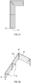
- Figs. 13 to 15 show a second alignment adaptor 56.
- the alignment adaptor 56 has a generally L shape cross section in plan view, except that there is an inclined web 58 between the two limbs 60 of the L shape, defining the apex of the L.
- Three mounting holes 62 are provided in the web 58 to permit mounting of the adaptor 56 to a fence post 40 or the like.
- a pair of mounting holes 64 are provided on a one of the limbs 60 of the L with a threaded boss 66 to permit a bracket member 10 to be mounted thereto.
- the second alignment adaptor 56 is formed for instance of folded steel.
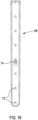
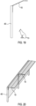
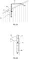
- Figs. 16 to 18 show an extension member 68 which enables a bracket member 10 to extend higher than would otherwise be the case.
- the extension member 68 is formed of plain channel section with the height of the side walls 70 increasing upwardly in use.
- a plurality of mounting holes 72 are provided in the base of the channel of the extension member 68, to permit mounting thereof to a fence post 40 or the like, or an alignment adaptor 36, 56.
- Spaced upwardly from the lower end of the extension member 68 is an outwardly extending flap 74 to supportingly receive the lower end of a bracket member 10 mounted thereto.
- a pair of folded tabs 76 are provided extending inwardly from the side walls 70 of the channel at an upper end of the extension member 68.
- An extension member 68 can again be provided by stamping or pressing galvanised steel.
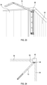
- a bracket member 10 can be mounted to the extension member 68 by sliding the lower end of the mounting part 12 so as to engage against the flap 74, with the tabs 76 retaining the bracket member 10 in a sliding fit relative to the channel of the extension member 68. Screws can then pass through a hole 22 in the base 14 of the bracket member 10 and the extension member 68, to engage in a fence post 40 for example as shown in Figs. 25 and 26 , or an alignment adaptor 36 as shown for instance in Figs. 27 and 28 .
- a barrier assembly which can be formed from a number of bracket members, alignment adaptors and/or extension members. This permits the same bracket members to be usable in a straight section of fencing such as shown for instance in Fig. 20 , or in corners as shown for instance in Figs. 21 to 24 .
- the extension members enable the same bracket members to be used for instance with lower fences or walls. Therefore a kit of parts can be provided with only two or three different components but which can be used in combination as required.
- bracket members may take a different form.
- alignment adaptors can take different forms, and it is to be realised that both forms described can simply be turned through 180° for use in an opposite handed corner.
- the extension members may take a different form, and could for instance be of a different size if required.
Landscapes
- Engineering & Computer Science (AREA)
- Architecture (AREA)
- Civil Engineering (AREA)
- Structural Engineering (AREA)
- Life Sciences & Earth Sciences (AREA)
- Zoology (AREA)
- Insects & Arthropods (AREA)
- Birds (AREA)
- Health & Medical Sciences (AREA)
- General Health & Medical Sciences (AREA)
- Toxicology (AREA)
- Environmental Sciences (AREA)
- Fencing (AREA)
- Casings For Electric Apparatus (AREA)
Claims (10)
- Barriereanordnung, wobei die Anordnung Folgendes umfasst:ein Halterungselement (10), das einen ersten Montageteil (12) und einen zweiten Barriereteil umfasst, wobei der zweite Barriereteil (24) bei Gebrauch in einem Winkel verläuft, der relativ zu dem ersten Montageteil von der Vertikalen geneigt ist; undeinen Ausrichtungsadapter (36), der an einer Oberfläche eines Zaunpfostens (40) montierbar ist, wobei der Ausrichtungsadapter eine offene Oberfläche (38), die mit der Oberfläche des Zaunpfostens in Eingriff bringbar ist, und eine flache Eingriffsfläche (42) umfasst, die relativ zu der offenen Oberfläche um im Wesentlichen 45° geneigt ist;wobei das Halterungselement an der offenen Oberfläche des Ausrichtungsadapters montierbar ist, so dass das Montageteil relativ zu der Oberfläche des Zaunpfostens um eine vertikale Achse geneigt ist.
- Barriereanordnung nach Anspruch 1, bei der die offene Oberfläche eine Vielzahl von Durchgangslöchern enthält, durch die sich ein Befestigungsmittel erstrecken kann.
- Barriereanordnung nach Anspruch 1 oder 2, wobei in einem montierten Zustand der Barriereanordnung die Eingriffsfläche relativ zu der Oberfläche eines Zaunpfostens geneigt ist, an dem der Ausrichtungsadapter montiert ist.
- Barriereanordnung nach Anspruch 3, bei der sich in einem montierten Zustand der Barriereanordnung die Eingriffsfläche in im Wesentlichen 45° zu der Oberfläche eines Zaunpfostens erstreckt, an dem der Ausrichtungsadapter montiert ist.
- Barriereanordnung nach Anspruch 3 oder 4, bei der die Eingriffsfläche so konfiguriert ist, dass sie in jede Richtung relativ zu der Oberfläche eines Zaunpfostens geneigt werden kann.
- Barriereanordnung nach einem der Ansprüche 3 bis 5, bei der die Eingriffsfläche eine Vielzahl von Löchern enthält.
- Barriereanordnung nach einem der vorhergehenden Ansprüche, bei der der Ausrichtungsadapter in der Form eines Hohlkörpers vorliegt, der in der Draufsicht zumindest im Allgemeinen dreieckig mit einer gekrümmten Seite ist.
- Barriereanordnung nach einem vorhergehenden Anspruch, wobei sich zwischen der offenen Oberfläche und der Eingriffsfläche eine gekrümmte Fläche erstreckt.
- Barriereanordnung nach Anspruch 8, sofern abhängig von Anspruch 2, wobei die Vielzahl von Durchgangslöchern ein Paar Montagelöcher umfasst, die in der Verbindung zwischen der Eingriffsfläche und der gekrümmten Fläche bereitgestellt sind, um ein Montieren des Adapters am Zaunpfosten zu ermöglichen.
- Barriereanordnung nach einem der vorhergehenden Ansprüche, wobei sich zwischen den Halterungselementen Barrieremittel erstrecken.
Applications Claiming Priority (2)
| Application Number | Priority Date | Filing Date | Title |
|---|---|---|---|
| GB1820790.2A GB2580051B (en) | 2018-12-20 | 2018-12-20 | Barrier assembly |
| PCT/GB2019/053677 WO2020128524A2 (en) | 2018-12-20 | 2019-12-20 | Barrier assembly |
Publications (3)
| Publication Number | Publication Date |
|---|---|
| EP3874103A2 EP3874103A2 (de) | 2021-09-08 |
| EP3874103C0 EP3874103C0 (de) | 2024-12-11 |
| EP3874103B1 true EP3874103B1 (de) | 2024-12-11 |
Family
ID=65364505
Family Applications (1)
| Application Number | Title | Priority Date | Filing Date |
|---|---|---|---|
| EP19831857.8A Active EP3874103B1 (de) | 2018-12-20 | 2019-12-20 | Barriereanordnung |
Country Status (4)
| Country | Link |
|---|---|
| US (1) | US11702861B2 (de) |
| EP (1) | EP3874103B1 (de) |
| GB (1) | GB2580051B (de) |
| WO (1) | WO2020128524A2 (de) |
Families Citing this family (1)
| Publication number | Priority date | Publication date | Assignee | Title |
|---|---|---|---|---|
| GB2700283A (en) * | 2024-04-04 | 2026-01-07 | Protectapet Ltd | An extender for a barrier portion of a bracket, a bracket assembly, and an animal containment system |
Family Cites Families (17)
| Publication number | Priority date | Publication date | Assignee | Title |
|---|---|---|---|---|
| US1980852A (en) * | 1933-12-29 | 1934-11-13 | American Steel & Wire Co | Fence post extension arm |
| US2199518A (en) * | 1937-02-23 | 1940-05-07 | Harry Weldon M Coleman | Fence |
| US4093187A (en) * | 1975-12-22 | 1978-06-06 | Charles Elbert Robinson | Fencing stay system |
| US4110944A (en) * | 1977-01-14 | 1978-09-05 | Gaynor Carlson | Animal protective guard |
| DE4203267A1 (de) * | 1991-02-06 | 1992-08-13 | Thiele Verwaltungs Gmbh | Sicherungskonstruktion fuer den oberrand einer einfriedung |
| US6199831B1 (en) * | 1999-06-30 | 2001-03-13 | Paul H. Patrick | Non-electric perimeter fence |
| ZA200405004B (en) * | 2003-04-24 | 2005-07-27 | Peter Colin Joao | Support bracket |
| US20070017156A1 (en) * | 2005-07-21 | 2007-01-25 | North States Industries, Inc. | Security Gate |
| JP4788493B2 (ja) * | 2006-05-29 | 2011-10-05 | 緑 松本 | 忍返しおよび該忍返しをとりつけた防犯用フエンス |
| US7461833B1 (en) * | 2007-01-30 | 2008-12-09 | Gibbs Edward L | Picket assembly for a post |
| US8616531B2 (en) * | 2009-01-07 | 2013-12-31 | Purrfect Cat Fence, LLC | Pivoting fencing apparatus and fencing system |
| US8308141B1 (en) * | 2012-01-06 | 2012-11-13 | Mellins Sue M | Animal-resistant fence and method for assembling and using the same |
| DE202016103374U1 (de) * | 2015-07-01 | 2016-07-25 | Stefan Dölling | Übersteigschutz |
| US20170030083A1 (en) * | 2015-07-31 | 2017-02-02 | Vito Matturro | Privacy and weather protection barrier |
| US10244733B1 (en) * | 2016-03-07 | 2019-04-02 | John G. Lillich | Adaptable fence extension assembly |
| GB2577038A (en) * | 2018-08-23 | 2020-03-18 | Protectapet Ltd | Fencing |
| FR3086962B1 (fr) * | 2018-10-08 | 2020-10-30 | Sarl Mouneyrac Etudes | Bavolet et element de cloture equipe d'un tel bavolet |
-
2018
- 2018-12-20 GB GB1820790.2A patent/GB2580051B/en active Active
-
2019
- 2019-12-20 EP EP19831857.8A patent/EP3874103B1/de active Active
- 2019-12-20 WO PCT/GB2019/053677 patent/WO2020128524A2/en not_active Ceased
- 2019-12-20 US US17/416,364 patent/US11702861B2/en active Active
Also Published As
| Publication number | Publication date |
|---|---|
| US20220074227A1 (en) | 2022-03-10 |
| GB2580051B (en) | 2021-08-18 |
| WO2020128524A3 (en) | 2020-07-30 |
| US11702861B2 (en) | 2023-07-18 |
| EP3874103A2 (de) | 2021-09-08 |
| WO2020128524A2 (en) | 2020-06-25 |
| EP3874103C0 (de) | 2024-12-11 |
| GB201820790D0 (en) | 2019-02-06 |
| GB2580051A (en) | 2020-07-15 |
Similar Documents
| Publication | Publication Date | Title |
|---|---|---|
| US7419141B2 (en) | Solid barrier system | |
| US20090026431A1 (en) | Picket and rail fence | |
| US4986513A (en) | Fence connector assembly | |
| CA2870710C (en) | Fence rail and bracket system | |
| US20070170410A1 (en) | System, method and Apparatus for Assembling a Picket Fence | |
| US20110302874A1 (en) | Post wrap device | |
| US20020121634A1 (en) | Modular fence system | |
| US20120235105A1 (en) | Quick clip for fence posts | |
| EP4107347B1 (de) | Zaun | |
| US6948704B2 (en) | Bracket assembly for connecting rails of various configurations to a support structure | |
| US20090152524A1 (en) | Fence stabilization system | |
| US9518404B2 (en) | Fence post system | |
| EP3874103B1 (de) | Barriereanordnung | |
| US8578662B1 (en) | Window well enclosure with attachable steps | |
| US7168688B2 (en) | Privacy fence | |
| GB2466778A (en) | A reinforceable fence post | |
| US11939788B2 (en) | Fence panel having tabs and method of installation thereof | |
| US20220042262A1 (en) | Temporary Barrier | |
| US10794081B2 (en) | Fence rail with concealed fastener and anti-rattling capabilities | |
| US20260028853A1 (en) | Fence | |
| AU2020227118B2 (en) | Panel Lock Fence | |
| JP3586545B2 (ja) | 塀 | |
| JP2019027200A (ja) | フェンス | |
| JP2002235371A (ja) | バルコニーフェンス、バルコニーフェンスの取付け構造及び取付け方法 | |
| JPH0727245U (ja) | ケーブル布設用支持金具 |
Legal Events
| Date | Code | Title | Description |
|---|---|---|---|
| STAA | Information on the status of an ep patent application or granted ep patent |
Free format text: STATUS: UNKNOWN |
|
| STAA | Information on the status of an ep patent application or granted ep patent |
Free format text: STATUS: THE INTERNATIONAL PUBLICATION HAS BEEN MADE |
|
| PUAI | Public reference made under article 153(3) epc to a published international application that has entered the european phase |
Free format text: ORIGINAL CODE: 0009012 |
|
| STAA | Information on the status of an ep patent application or granted ep patent |
Free format text: STATUS: REQUEST FOR EXAMINATION WAS MADE |
|
| 17P | Request for examination filed |
Effective date: 20210520 |
|
| AK | Designated contracting states |
Kind code of ref document: A2 Designated state(s): AL AT BE BG CH CY CZ DE DK EE ES FI FR GB GR HR HU IE IS IT LI LT LU LV MC MK MT NL NO PL PT RO RS SE SI SK SM TR |
|
| DAV | Request for validation of the european patent (deleted) | ||
| DAX | Request for extension of the european patent (deleted) | ||
| RIN1 | Information on inventor provided before grant (corrected) |
Inventor name: DAVIES, SIMON KEITH |
|
| STAA | Information on the status of an ep patent application or granted ep patent |
Free format text: STATUS: EXAMINATION IS IN PROGRESS |
|
| 17Q | First examination report despatched |
Effective date: 20230224 |
|
| GRAP | Despatch of communication of intention to grant a patent |
Free format text: ORIGINAL CODE: EPIDOSNIGR1 |
|
| STAA | Information on the status of an ep patent application or granted ep patent |
Free format text: STATUS: GRANT OF PATENT IS INTENDED |
|
| INTG | Intention to grant announced |
Effective date: 20240705 |
|
| GRAS | Grant fee paid |
Free format text: ORIGINAL CODE: EPIDOSNIGR3 |
|
| GRAA | (expected) grant |
Free format text: ORIGINAL CODE: 0009210 |
|
| STAA | Information on the status of an ep patent application or granted ep patent |
Free format text: STATUS: THE PATENT HAS BEEN GRANTED |
|
| RBV | Designated contracting states (corrected) |
Designated state(s): AL AT BE BG CH CY CZ DE DK EE ES FI FR GR HR HU IE IS IT LI LT LU LV MC MK MT NL NO PL PT RO RS SE SI SK SM TR |
|
| AK | Designated contracting states |
Kind code of ref document: B1 Designated state(s): AL AT BE BG CH CY CZ DE DK EE ES FI FR GR HR HU IE IS IT LI LT LU LV MC MK MT NL NO PL PT RO RS SE SI SK SM TR |
|
| REG | Reference to a national code |
Ref country code: CH Ref legal event code: EP |
|
| REG | Reference to a national code |
Ref country code: DE Ref legal event code: R096 Ref document number: 602019063463 Country of ref document: DE |
|
| REG | Reference to a national code |
Ref country code: IE Ref legal event code: FG4D |
|
| U01 | Request for unitary effect filed |
Effective date: 20241219 |
|
| U07 | Unitary effect registered |
Designated state(s): AT BE BG DE DK EE FI FR IT LT LU LV MT NL PT RO SE SI Effective date: 20250113 |
|
| U20 | Renewal fee for the european patent with unitary effect paid |
Year of fee payment: 6 Effective date: 20250220 |
|
| PG25 | Lapsed in a contracting state [announced via postgrant information from national office to epo] |
Ref country code: HR Free format text: LAPSE BECAUSE OF FAILURE TO SUBMIT A TRANSLATION OF THE DESCRIPTION OR TO PAY THE FEE WITHIN THE PRESCRIBED TIME-LIMIT Effective date: 20241211 |
|
| PG25 | Lapsed in a contracting state [announced via postgrant information from national office to epo] |
Ref country code: ES Free format text: LAPSE BECAUSE OF FAILURE TO SUBMIT A TRANSLATION OF THE DESCRIPTION OR TO PAY THE FEE WITHIN THE PRESCRIBED TIME-LIMIT Effective date: 20241211 |
|
| PG25 | Lapsed in a contracting state [announced via postgrant information from national office to epo] |
Ref country code: NO Free format text: LAPSE BECAUSE OF FAILURE TO SUBMIT A TRANSLATION OF THE DESCRIPTION OR TO PAY THE FEE WITHIN THE PRESCRIBED TIME-LIMIT Effective date: 20250311 |
|
| PG25 | Lapsed in a contracting state [announced via postgrant information from national office to epo] |
Ref country code: GR Free format text: LAPSE BECAUSE OF FAILURE TO SUBMIT A TRANSLATION OF THE DESCRIPTION OR TO PAY THE FEE WITHIN THE PRESCRIBED TIME-LIMIT Effective date: 20250312 |
|
| PG25 | Lapsed in a contracting state [announced via postgrant information from national office to epo] |
Ref country code: RS Free format text: LAPSE BECAUSE OF FAILURE TO SUBMIT A TRANSLATION OF THE DESCRIPTION OR TO PAY THE FEE WITHIN THE PRESCRIBED TIME-LIMIT Effective date: 20250311 |
|
| PG25 | Lapsed in a contracting state [announced via postgrant information from national office to epo] |
Ref country code: SM Free format text: LAPSE BECAUSE OF FAILURE TO SUBMIT A TRANSLATION OF THE DESCRIPTION OR TO PAY THE FEE WITHIN THE PRESCRIBED TIME-LIMIT Effective date: 20241211 |
|
| PG25 | Lapsed in a contracting state [announced via postgrant information from national office to epo] |
Ref country code: PL Free format text: LAPSE BECAUSE OF FAILURE TO SUBMIT A TRANSLATION OF THE DESCRIPTION OR TO PAY THE FEE WITHIN THE PRESCRIBED TIME-LIMIT Effective date: 20241211 |
|
| PG25 | Lapsed in a contracting state [announced via postgrant information from national office to epo] |
Ref country code: IS Free format text: LAPSE BECAUSE OF FAILURE TO SUBMIT A TRANSLATION OF THE DESCRIPTION OR TO PAY THE FEE WITHIN THE PRESCRIBED TIME-LIMIT Effective date: 20250411 |
|
| PG25 | Lapsed in a contracting state [announced via postgrant information from national office to epo] |
Ref country code: SK Free format text: LAPSE BECAUSE OF FAILURE TO SUBMIT A TRANSLATION OF THE DESCRIPTION OR TO PAY THE FEE WITHIN THE PRESCRIBED TIME-LIMIT Effective date: 20241211 |
|
| PG25 | Lapsed in a contracting state [announced via postgrant information from national office to epo] |
Ref country code: CZ Free format text: LAPSE BECAUSE OF FAILURE TO SUBMIT A TRANSLATION OF THE DESCRIPTION OR TO PAY THE FEE WITHIN THE PRESCRIBED TIME-LIMIT Effective date: 20241211 |
|
| REG | Reference to a national code |
Ref country code: CH Ref legal event code: PL |
|
| PG25 | Lapsed in a contracting state [announced via postgrant information from national office to epo] |
Ref country code: MC Free format text: LAPSE BECAUSE OF FAILURE TO SUBMIT A TRANSLATION OF THE DESCRIPTION OR TO PAY THE FEE WITHIN THE PRESCRIBED TIME-LIMIT Effective date: 20241211 |
|
| PLBE | No opposition filed within time limit |
Free format text: ORIGINAL CODE: 0009261 |
|
| STAA | Information on the status of an ep patent application or granted ep patent |
Free format text: STATUS: NO OPPOSITION FILED WITHIN TIME LIMIT |
|
| PG25 | Lapsed in a contracting state [announced via postgrant information from national office to epo] |
Ref country code: CH Free format text: LAPSE BECAUSE OF NON-PAYMENT OF DUE FEES Effective date: 20241231 |
|
| PG25 | Lapsed in a contracting state [announced via postgrant information from national office to epo] |
Ref country code: IE Free format text: LAPSE BECAUSE OF NON-PAYMENT OF DUE FEES Effective date: 20241220 |
|
| 26N | No opposition filed |
Effective date: 20250912 |
|
| U20 | Renewal fee for the european patent with unitary effect paid |
Year of fee payment: 7 Effective date: 20251215 |