EP3872500A1 - Automated analyzer - Google Patents
Automated analyzer Download PDFInfo
- Publication number
- EP3872500A1 EP3872500A1 EP19876425.0A EP19876425A EP3872500A1 EP 3872500 A1 EP3872500 A1 EP 3872500A1 EP 19876425 A EP19876425 A EP 19876425A EP 3872500 A1 EP3872500 A1 EP 3872500A1
- Authority
- EP
- European Patent Office
- Prior art keywords
- dispensing
- specimen
- analysis
- standard substance
- reaction vessel
- Prior art date
- Legal status (The legal status is an assumption and is not a legal conclusion. Google has not performed a legal analysis and makes no representation as to the accuracy of the status listed.)
- Granted
Links
Images



Classifications
-
- G—PHYSICS
- G01—MEASURING; TESTING
- G01N—INVESTIGATING OR ANALYSING MATERIALS BY DETERMINING THEIR CHEMICAL OR PHYSICAL PROPERTIES
- G01N35/00—Automatic analysis not limited to methods or materials provided for in any single one of groups G01N1/00 - G01N33/00; Handling materials therefor
- G01N35/10—Devices for transferring samples or any liquids to, in, or from, the analysis apparatus, e.g. suction devices, injection devices
- G01N35/1009—Characterised by arrangements for controlling the aspiration or dispense of liquids
- G01N35/1016—Control of the volume dispensed or introduced
-
- G—PHYSICS
- G01—MEASURING; TESTING
- G01N—INVESTIGATING OR ANALYSING MATERIALS BY DETERMINING THEIR CHEMICAL OR PHYSICAL PROPERTIES
- G01N35/00—Automatic analysis not limited to methods or materials provided for in any single one of groups G01N1/00 - G01N33/00; Handling materials therefor
- G01N2035/00465—Separating and mixing arrangements
- G01N2035/00564—Handling or washing solid phase elements, e.g. beads
-
- G—PHYSICS
- G01—MEASURING; TESTING
- G01N—INVESTIGATING OR ANALYSING MATERIALS BY DETERMINING THEIR CHEMICAL OR PHYSICAL PROPERTIES
- G01N35/00—Automatic analysis not limited to methods or materials provided for in any single one of groups G01N1/00 - G01N33/00; Handling materials therefor
- G01N35/0098—Automatic analysis not limited to methods or materials provided for in any single one of groups G01N1/00 - G01N33/00; Handling materials therefor involving analyte bound to insoluble magnetic carrier, e.g. using magnetic separation
Definitions
- the present invention relates to an automatic analysis device configured to analyze a specimen.
- an LC-MS in which a liquid chromatography (LC) and a mass spectrometry (MS) are connected online is used.
- LC liquid chromatography
- MS mass spectrometry
- the use of this LC-MS also extends to a field of clinical test in which analysis of a biological specimen such as blood or urine is performed by an automatic analysis device.
- the LC-MS When the biological specimen such as blood or urine (hereinafter simply referred to as specimen) is analyzed by the LC-MS, it is necessary to perform a pretreatment to improve a degree of purification of the specimen.
- the pretreatment of the specimen include solid phase extraction (SPE), liquid-liquid extraction (LLE), and the like.
- SPE solid phase extraction
- LLE liquid-liquid extraction
- the SPE is easy to be connected to the LC-MS online, it is possible to automate the pretreatment by the SPE and the analysis by the LC-MS in an integrated manner.
- PTL 1 discloses an analysis device including: a sample disc on which a sample container is mounted; a reagent disc on which a reagent container is mounted; a first disc on which a first container for purifying a measurement target component of the sample is mounted; a second disc on which a second container for purifying the sample purified in the first container is mounted; and a mass analyzing unit for measuring the sample purified in the second container.
- a predetermined amount of a solution of a specimen or a reagent is dispensed into a reaction vessel to perform various processes related to the analysis. For example, during measurement of a drug concentration in blood, a deproteinization treatment is performed in which a reagent such as an organic solvent is dispensed and added as a deproteinization agent to the blood dispensed into the reaction vessel to denature and precipitate proteins in the blood.
- a reagent such as an organic solvent
- an influence of dispensing accuracy on an analysis result is inevitably large. For example, when the dispensing amount of the reagent is less than the predetermined amount, an amount of a drug to be eluted decreases and thus shows a false low value, which may decrease analysis accuracy.
- the invention has been made in view of the above circumstances, and an object thereof is to provide an automatic analysis device and an analysis method capable of reliably detecting an abnormality in a dispensing amount of a solution such as a specimen or a reagent to be dispensed and preventing a decrease in analysis accuracy.
- the invention provides an automatic analysis device including: a first dispensing mechanism that dispenses an analysis target specimen in a reaction vessel; a second dispensing mechanism that dispenses another dispensing object different from the specimen in the reaction vessel; an analysis mechanism that detects and analyzes a specific component in a reaction solution in which the specimen dispensed in the reaction vessel and the another dispensing object are mixed to each other; and a control device, in which the control device determines whether a dispensed liquid amount of the another dispensing object is abnormal or not, based on a detection result of a standard substance for dispensing inspection which has been added in advance to the another dispensing object, which is detected at the same time with detection of an analysis target component of the specimen in the reaction solution in the analysis mechanism.
- an automatic analysis device in which a liquid chromatography and a mass spectrometry (LC-MS) are combined as an analysis mechanism with a specimen pretreatment function is exemplified and described
- the invention also can be applied to, for example, an automatic analysis device in which a separation unit such as a capillary electrophoresis and a detector such as an absorptiometer are combined as the analysis mechanism.
- a deproteinizing agent is exemplified and described as a target to which a standard substance for dispensing inspection is added
- the invention can be applied to all solutions to be dispensed into a specimen during analysis, such as an internal standard substance or a magnetic bead.
- FIG. 1 is a diagram schematically illustrating an overall configuration of the automatic analysis device according to the present embodiment.
- an automatic analysis device 100 schematically includes an analysis unit 101 for performing an analysis operation, a control unit 102 for controlling an overall operation of the device, an input unit 103 for a user to input information to the device, a display unit 104 for displaying information to the user, and a storage unit 105 such as a storage medium for storing various information related to the control of the automatic analysis device 100.
- the control unit 102, the input unit 103, the display unit 104, and the storage unit 105 constitute a control device that controls the overall operation of the automatic analysis device 100.
- the input unit 103 and the display unit 104 are separately shown, but the input unit 103 and the display unit 104 may be integrally configured as, for example, a touch panel type monitor.
- the analysis unit 101 includes: a transport mechanism 112 that transports a specimen container 111 storing the specimen, which is an analysis target, to a specimen dispensing position; a reaction vessel disc 120 capable of retaining a solution in a reaction vessel 116 at a constant temperature by mounting the reaction vessel 116 in a plurality of opening parts 119; a reagent disc 122 that retains a plurality of reagent containers 121 storing reagents; a specimen dispensing mechanism 113 that dispenses the specimen from the specimen container 111 transported to the specimen dispensing position to the reaction vessel 116 on the reaction vessel disc 120; a reagent dispensing mechanism 123 that dispenses the reagents from the reagent containers 121 to the reaction vessel 116 on the reaction vessel disc 120; a dispensing chip-mounted rack 115 on which an unused disposable dispensing chip 115a attached to a nozzle of the specimen dispensing mechanism 113 is mounted; a dispensing chip attaching and detaching unit
- the magnetic separation mechanism 124 is provided on a rotating orbit 126 of the reagent dispensing mechanism 123.
- the reagent dispensing mechanism 123 is capable of discharging the reagent to the reaction vessel 116 supported by the magnetic separation mechanism 124 or sucking the solution in the reaction vessel 116.
- the reaction vessel disc 120 functions as an incubator that keeps the reaction vessel 116 installed in the opening part 119 at a constant temperature, and incubates the reaction vessel 116 installed in the opening part 119 for a certain period of time.
- the separation unit 131 is, for example, a liquid chromatography (LC) and includes a column or the like having a function of separating components in a reaction solution dispensed by the dispensing mechanism for separation unit 132 .
- the separation unit 131 separates the components in the reaction solution dispensed from the reaction vessel 116 by the dispensing mechanism for separation unit 132, and sequentially introduces the separated components into the mass analyzing unit 133.
- LC liquid chromatography
- the mass analyzing unit 133 is, for example, a mass spectrometry (MS) and includes an electron multiplier or the like having a function of ionizing and mass-analyzing the component introduced from the separation unit 131.
- the mass analyzing unit 133 ionizes the component introduced from the separation unit 131, detects an amount of ions (that is, an amount of the component), and outputs a detection result to the control unit 102.
- the control unit 102 calculates a concentration value of the component in the specimen using the detection result (the amount of ions) from the mass analyzing unit 133 and a calibration curve obtained in advance, stores the concentration value in the storage unit 105 as an analysis result, and displays the analysis result on the display unit 104.
- a method for obtaining the calibration curve for example, first, a standard substance having a known concentration is analyzed for a plurality of concentrations. Then, with respect to a mass/charge ratio (m/z) of ions derived from the standard substance, a time-dependent ion amount, that is, a time-dependent ionic strength (mass chromatogram) is obtained, and a peak area of the mass chromatogram is obtained.
- the calibration curve is created based on a relation between the area and the concentration of the standard substance.
- the peak area of the mass chromatogram is obtained for an analysis target specimen, and the concentration of the analysis target component is determined based on a correspondence between the peak area of the mass chromatogram and the calibration curve.
- the ionic strength to be detected is standardized based on an ionic strength derived from an internal standard substance, a comparison between data can be performed under high accuracy. That is, it is possible to compare and verify the ionic strength between each analysis, which may show some fluctuation for each analysis due to an influence of a specimen pretreatment, specimen injection into the LC-MS, ionization in the LC-MS, and the like. This method is called an internal standard method.
- FIG. 2 is a diagram illustrating an example of a pretreatment step of the analysis process by the automatic analysis device.
- the unused reaction vessel 116 is installed from the reaction vessel-mounted rack 117 on the opening part 119 of the reaction vessel disc 120 by the transport mechanism 118.
- the specimen dispensing mechanism 113 is made to access the dispensing chip attaching and detaching unit 114, and then the dispensing chip 115a is attached to a tip of the nozzle.
- a specimen containing an analysis target component 201 is sucked from the specimen container 111 via the dispensing chip 115a by the specimen dispensing mechanism 113, and then discharged into the reaction vessel 116 on the reaction vessel disc 120 (step S200) .
- the dispensing chip attaching and detaching unit 114 discards the used dispensing chip 115a and attaches an unused dispensing chip 115a.
- a deproteinizing agent is sucked from the reagent container 121 on the reagent disc 122 by the reagent dispensing mechanism 123, and then discharged into the reaction vessel 116 (step S202) .
- the reagent container 121 storing the deproteinizing agent according to the present embodiment is added with a predetermined standard substance for dispensing inspection 205 having a known concentration.
- a suspension of magnetic beads 207 is sucked from the reagent container 121 on the reagent disc 122 by the reagent dispensing mechanism 123, and then discharged into the reaction vessel 116 (step S205).
- the reaction vessel 116 into which the specimen, the internal standard substance 203, and the magnetic beads 207 are dispensed is transported to the magnetic separation mechanism 124 by the transport mechanism 125 to clean the magnetic beads 207 (step S205) .
- the magnetic separation mechanism 124 With the magnetic separation mechanism 124, the magnetic beads 207 retaining the analysis target component 201, the internal standard substance 203, and the standard substance for dispensing inspection 205 are collected on an inner wall surface of the reaction vessel 116 by magnetic force of a magnet 209 arranged at a position along an outer surface of the reaction vessel 116 (in FIG. 2 , shown as a magnetic bead group 210).
- the reagent dispensing mechanism 123 sucks the solution in the reaction vessel 116 and then discards the same.
- the analysis target component 201, the internal standard substance 203, and the standard substance for dispensing inspection 205 retained by the magnetic beads 207 and the magnetic beads 207 remain in the reaction vessel 116. Then, a cleaning solution for cleaning impurities other than the substances retained by the magnetic beads 207 (the analysis target component 201, the internal standard substance 203, and the standard substance for dispensing inspection 205) is sucked from the reagent container 121 on the reagent disc 122 by the reagent dispensing mechanism 123, and then discharged into the reaction vessel 116. At this time, constraint by the magnetic force of the magnet 209 to the magnetic beads 207 may be temporarily released.
- the reagent dispensing mechanism 123 cleans the magnetic beads 207 by sucking the solution (the cleaning solution) in the reaction vessel 116 and the discarding the solution.
- the solution (purified solution) in the reaction vessel 116 is sucked by the reagent dispensing mechanism 123 and then discharged into an unused reaction vessel 116 on the reaction vessel disc 120, which is different from the reaction vessel 116 and arranged on the magnetic separation mechanism 124 (step S207). If necessary, incubation is performed on the purified solution stored in the reaction vessel 116 on the reaction vessel disc 120.
- the purified solution obtained by the above pretreatment step is sucked from the reaction vessel 116 and then discharged into the separation unit 131 by the dispensing mechanism for separation unit 132, and the component separated by the separation unit 131 is ionized by the mass analyzing unit 133 to detect the amount of ions (that is, the amount of the component) thereof.
- the detection result of the mass analyzing unit 133 is output to the control unit 102, and the concentration value of the component in the specimen is calculated using the calibration curve.
- the dispensing amount abnormality determination process of the present embodiment is a process of determining presence or absence of an abnormality in a dispensing amount of a solution such as a reagent to be dispensed into a specimen, which is an analysis target.
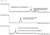
- FIGS. 3 to 5 are diagrams schematically showing examples of a mass chromatogram obtained by the analysis unit for each of the standard substance for dispensing inspection, the internal standard substance, the standard substance, and the analysis target component, in which a vertical axis shows the ionic strength, and a horizontal axis shows an LC retention time.
- FIG. 3 illustrates a case where the mass chromatograms derived from the standard substance for dispensing inspection, the internal standard substance, and the standard substance are compared to each other
- FIG. 4 illustrates a case where the mass chromatograms derived from the standard substance for dispensing inspection, the internal standard substance, and the analysis target component are compared to each other
- FIG. 5 illustrates a case where the mass chromatograms derived from the standard substance for dispensing inspection, the internal standard substance, and the analysis target component are compared to each other.
- the standard substance for dispensing inspection is added in advance to the solution (for example, the deproteinizing agent) , which is a target solution of the dispensing amount abnormality determination process.
- the solution for example, the deproteinizing agent
- the standard substance having a known concentration is analyzed according to the steps of the analysis process, and a mass chromatogram of the standard substance (see FIG. 3 and the like) is obtained in advance and recorded as reference data for determination in the storage unit 105.
- the comparison is performed after standardizing the data.
- the data standardization is performed by, for example, comparing the peaks at the same retention time and then calculating a percentage of the peak area of the obtained data when the peak area of the reference data for determination is 100%. For example, when the peak area of the obtained data is 97% of the peak area of the reference data for determination, it is determined that there is a difference of 3%.
- the difference ratio given by the above (Equation 1) is compared to a preset difference ratio threshold value, and the presence or absence of the abnormality in the dispensing amount is determined based on a comparison result. That is, the presence or absence of the abnormality in the dispensing amount can be temporarily determined by calculating the difference ratio at the same time as calculating the concentration of the analysis target component and comparing the difference ratio to the difference ratio threshold value.
- the difference ratio threshold value which is a determination standard, is preset before the analysis process and the dispensing amount abnormality determination process, and is stored in the storage unit 105 in the same manner as the reference data for determination.
- the difference ratio threshold value may be appropriately input by an operator. It is known that a standard measurement error of the LC-MS is approximately 5% to 10%. Therefore, in the present embodiment, a case where the difference ratio threshold value is set to 15% will be exemplified and described. That is, when the difference ratio exceeds 15%, it is determined that there is an abnormality in the dispensing amount. Since it is considered that the measurement error depends on devices, the difference ratio threshold value may be set for each device so as to further improve accuracy of abnormality determination of the dispensing amount.
- the peak area derived from the standard substance for dispensing inspection is larger in the data obtained during specimen analysis than in the reference data for determination. Therefore, when the difference ratio exceeds the difference ratio threshold value (15%), it is determined that there is an abnormality that the dispensing amount of the deproteinizing agent containing the standard substance for dispensing inspection increases.
- the amount of the deproteinizing agent for eluting the analysis target component is sufficient when the dispensing amount is normal, since an elution amount of the analysis target component does not change even if the dispensing amount of the deproteinizing agent increases, the peak area derived from the analysis target component does not change.
- the peak area derived from the standard substance for dispensing inspection is smaller in the data obtained during specimen analysis than in the reference data for determination. Therefore, when the difference ratio exceeds the difference ratio threshold value (15%), it is determined that there is an abnormality that the dispensing amount of the deproteinizing agent containing the standard substance for dispensing inspection decreases. In addition, the peak area derived from the analysis target component also decreases.
- the amount of the deproteinizing agent for eluting the analysis target component is sufficient when the dispensing amount is normal, when the dispensing amount of the deproteinizing agent decreases, at the same time, the elution amount of the analysis target component decreases and the peak area decreases, so that the concentration of the analysis target component is calculated to be small.
- the fluctuation may be corrected by standardizing the data derived from the analysis target component with the data derived from the standard substance for dispensing inspection.
- the standard substance for dispensing inspection is selected in consideration of the common technical knowledge, and a substance that can be captured by the magnetic beads during the specimen pretreatment, is sufficiently separated from the peak derived from the analysis target component or the internal standard substance in the mass chromatogram, and is detected within the range of the LC retention time in which the analysis target component is detected is selected as the standard substance for dispensing inspection.
- the analysis target component is captured by a hydrophobic interaction with the magnetic beads.
- a reverse phase column is usually used as a separation column. Retention on the reverse phase column is basically based on the hydrophobic interaction. Therefore, for example, it is desirable that the standard substance for dispensing inspection has a degree of hydrophobicity same as that of the analysis target component so as to be captured by the magnetic beads and the reverse phase column.
- a non-dissociated ionic compound is generally highly hydrophobic, so that the non-dissociated ionic compound can be strongly retained in the reverse phase column.
- a difference between dissociated and non-dissociated states arises from a relation between pH of a mobile phase of the LC and pKa of a compound.
- a retention behavior can be stabilized by setting the pKa of the analysis target component or the internal standard substance to a value that is +/-2 or more away from the pH of the mobile phase . That is, in consideration of the above and a balance between the pKa of the analysis target component or the internal standard substance and the mobile phase, it is important to select, as the standard substance for dispensing inspection, a substance that is sufficiently separated from the peak derived from the analysis target component or the internal standard substance in the mass chromatogram and is detected within the range of the LC retention time in which the analysis target component is detected.
- the m/z of the ions derived from the standard substance for dispensing inspection overlaps with the m/z of other detected ions to an extent of being unable to be identified by mass resolution of the MS, there is a possibility that an increase in peak strength of the ions derived from the standard substance for dispensing inspection is mistakenly recognized. In this case, it is difficult to determine whether or not there is an abnormality in the dispensing amount. Since a normal MS has a mass resolution of approximately 1 (m/z), it is desirable that the m/z of the peaks of the mass chromatograms derived from the analysis target component, the internal standard substance, and the standard substance for dispensing inspection are at least 1 [Da], and preferably separated by 3 [Da] or more.
- a device having an MS/MS method capable of detecting product ions as the MS used as the detector.
- MS/MS method even if the m/z of precursor ions of respective substances are the same, the m/z of the product ions of respective substances are different.
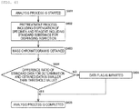
- FIG. 6 is a flowchart illustrating the analysis process including the dispensing amount abnormality determination process according to the present embodiment.
- step S601 when a start of the analysis process is instructed by the input unit 103 or the like (step S601), the control unit 102 performs the pretreatment step (see FIG. 2 ) including dispensation of the analysis target specimen and reagents including the standard substance for dispensing inspection (step S602). Then, the pretreated solution is dispensed from the reaction vessel 116 to the separation unit 131 by the dispensing mechanism for separation unit 132, and the mass chromatograph of the component in the solution separated by the separation unit 131 in the mass analyzing unit 133 is obtained (step S603). At this time, the mass chromatogram of the standard substance for dispensing inspection is obtained together with the mass chromatogram of the analysis target component of the specimen.
- the difference ratio between the reference data for determination and the obtained data of the standard substance for dispensing inspection is calculated, and then it is determined whether or not the difference ratio is smaller than the difference ratio threshold value (step S604).
- step S604 When a determination result in step S604 is YES, it is determined that there is no abnormality in the dispensing amount of the reagents including the standard substance for dispensing inspection in the pretreatment, the analysis result is stored in the storage unit 105 or displayed on the display unit 104, and then the analysis process is completed (step S605) .
- step S604 When the determination result in step S604 is NO, it is determined that there is an abnormality in the dispensing amount of the reagents including the standard substance for dispensing inspection in the pretreatment, a data flag indicating that it is determined that there is an abnormality in the dispensing amount is imparted to the analysis result (step S606), the analysis result is stored in the storage unit 105 or displayed on the display unit 104, and then the analysis process is completed (step S605).
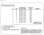
- FIG. 7 is a diagram illustrating an example of the analysis result displayed on the display unit.
- a specimen number that identifies a specimen, which is an analysis target; an analysis item corresponding to the analysis process performed on each specimen; a date and a time when measurement is performed; and a measured value, which is the amount of the component of the analysis target component contained in the analysis target specimen, are displayed correspondingly as a list of measured values.
- a data flag for example, display of "abnormality in dispensing amount" in a column of notes
- the specimen number in which the abnormality is determined the specimen number in which the abnormality is determined, a content of the abnormality (here, abnormality in dispensing amount), and a description of the content of the abnormality are displayed.
- a predetermined amount of the solution such as the specimen or the reagents
- a deproteinization treatment is performed in which a reagent such as an organic solvent is dispensed and added as the deproteinization agent to the blood dispensed into the reaction vessel to denature and precipitate proteins in the blood.
- a reagent such as an organic solvent
- an influence of dispensing accuracy on the analysis result is inevitably large .
- the dispensing amount of the reagent is less than the predetermined amount, an amount of a drug to be eluted decreases and thus shows a false low value, which may decrease analysis accuracy.
- the present embodiment is configured to include: the specimen dispensing mechanism 113 (first dispensing mechanism) that dispenses the analysis target specimen in the reaction vessel 116; the reagent dispensing mechanism 123 (second dispensing mechanism) that dispenses another dispensing object different from the specimen in the reaction vessel 116; the mass analyzing unit 133 (analysis mechanism) that detects and analyzes a specific component in a reaction solution in which the specimen dispensed in the reaction vessel 116 and the another dispensing object are mixed to each other; and the control unit 102 (control device) that determines whether a dispensed liquid amount of the another dispensing object is abnormal or not, based on a detection result of the standard substance for dispensing inspection which has been added in advance to the another dispensing object, which is detected at the same time with detection of the analysis target component of the specimen in the reaction solution in the analysis mechanism 133. Therefore, it is possible to reliably detect the abnormality in the dispensing amount of the solution such as the specimen or the
- a method for detecting the abnormality in the dispensing amount a method of comparing a detection result of a pressure sensor provided inside the dispensing nozzle of the dispensing mechanism to the reference data for determination and then detecting the abnormality based on a comparison result is considered.
- the pressure sensor that detects a pressure inside the dispensing nozzle of the dispensing mechanism is required, extra cost and space are required to provide the pressure sensor in the device.
- the cost and space for the pressure sensors are required according to the number of the dispensing mechanisms for which the abnormality is to be detected.
- the cost and space for the pressure sensor are not required and an increase in cost and space is prevented, and it is possible to reliably detect the abnormality in the dispensing amount of the solution such as the specimen or the reagent to be dispensed and prevent the decrease in analysis accuracy.
- a method of improving calibration accuracy of the dispensing amount as an influence of evaporation is small by dispensing the dispensing object having an amount (for example, 1 [ul] to 1000 [ul]) determined by a standard validation method and performing a test based on a dye method is also considered.
- an amount for example, 1 [ul] to 1000 [ul]
- this method since it is necessary to perform a test at a timing different from the analysis of the specimen, it is difficult to evaluate validity in the actual measurement for analyzing the specimen. During the test, the analysis of the specimen is stopped, which reduces a throughput, and furthermore, the user has to take time and effort to perform the test.
- the present embodiment since it is possible to determine the presence or absence of the abnormality in the dispensing amount at the same time as the analysis of the specimen, it is possible to evaluate the validity of the analysis in actual measurement and prevent a decrease in throughput and an increase in user effort, and it is also possible to reliably detect the abnormality in the dispensing amount of the solution such as the specimen or the reagent to be dispensed and prevent the decrease in analysis accuracy.
- the device when it is determined that there is an abnormality in the dispensing amount, the device is switched to a maintenance mode in addition the imparting of the data flag.
- FIG. 8 is a flowchart illustrating an analysis process including a dispensing amount abnormality determination process according to the present modification.
- step S601 when the start of the analysis process is instructed by the input unit 103 or the like (step S601), the control unit 102 performs the pretreatment step (see FIG. 2 ) including the dispensation of the analysis target specimen and the reagents including the standard substance for dispensing inspection (step S602). Then, the pretreated solution is dispensed from the reaction vessel 116 to the separation unit 131 by the dispensing mechanism for separation unit 132, and the mass chromatograph of the component in the solution separated by the separation unit 131 in the mass analyzing unit 133 is obtained (step S603) . At this time, the mass chromatogram of the standard substance for dispensing inspection is obtained together with the mass chromatogram of the analysis target component of the specimen.
- the difference ratio between the reference data for determination and the obtained data of the standard substance for dispensing inspection is calculated, and it is determined whether or not the difference ratio is smaller than the difference ratio threshold value (step S604).
- step S604 When the determination result in step S604 is YES, it is determined that there is no abnormality in the dispensing amount of the reagents including the standard substance for dispensing inspection in the pretreatment, the analysis result is stored in the storage unit 105 or displayed on the display unit 104, and then the analysis process is completed (step S605).
- step S604 When the determination result in step S604 is NO, it is determined that there is an abnormality in the dispensing amount of the reagents including the standard substance for dispensing inspection in the pretreatment, the data flag indicating that it is determined that there is an abnormality in the dispensing amount is imparted to the analysis result (step S606), the analysis result is stored in the storage unit 105 or displayed on the display unit 104, and then the analysis process is completed (step S701).
- the maintenance mode is a mode in which the device automatically cleans the dispensing nozzle and surrounding flow paths of the dispensing mechanism that is determined to be abnormal as the maintenance, and preparations are made for replacing the members of the dispensing mechanism.
- step S703 the analysis process is started without introducing the specimen to obtain the mass chromatogram (step S703), the difference ratio between the reference data for determination and the obtained data of the standard substance for dispensing inspection is calculated, and then it is determined whether or not the difference ratio is smaller than the difference ratio threshold value (step S704).
- step S704 When a determination result in step S704 is NO, the maintenance is performed again, and then the processes of steps S702 to S704 are repeated until it is determined that there is no abnormality in the dispensing amount.
- step S704 When the determination result in step S704 is YES, the maintenance mode is completed and the maintenance is completed (step S705).
- the present modification configured as above can exert effects same as those of the present embodiment.
- the invention is not limited to the above-described embodiment and modification, and includes various modifications.
- the above-described embodiment is described in detail for easy understanding of the invention, and is not necessarily limited to one having all the configurations described.
- Each of the above-described configurations, functions, and the like may be implemented by being designed partially or entirely using an integrated circuit or the like.
- the above-described configurations, functions, and the like may also be implemented by software by interpreting and executing a program that implements the functions using a processor.
Landscapes
- Physics & Mathematics (AREA)
- Health & Medical Sciences (AREA)
- Life Sciences & Earth Sciences (AREA)
- Chemical & Material Sciences (AREA)
- Analytical Chemistry (AREA)
- Biochemistry (AREA)
- General Health & Medical Sciences (AREA)
- General Physics & Mathematics (AREA)
- Immunology (AREA)
- Pathology (AREA)
- Automatic Analysis And Handling Materials Therefor (AREA)
- Other Investigation Or Analysis Of Materials By Electrical Means (AREA)
Abstract
Description
- The present invention relates to an automatic analysis device configured to analyze a specimen.
- As a method for analyzing specific components contained in a specimen, for example, an LC-MS in which a liquid chromatography (LC) and a mass spectrometry (MS) are connected online is used. The use of this LC-MS also extends to a field of clinical test in which analysis of a biological specimen such as blood or urine is performed by an automatic analysis device.
- When the biological specimen such as blood or urine (hereinafter simply referred to as specimen) is analyzed by the LC-MS, it is necessary to perform a pretreatment to improve a degree of purification of the specimen. Examples of the pretreatment of the specimen include solid phase extraction (SPE), liquid-liquid extraction (LLE), and the like. Particularly, since the SPE is easy to be connected to the LC-MS online, it is possible to automate the pretreatment by the SPE and the analysis by the LC-MS in an integrated manner.
- As a technique for performing such automation of the analysis using the SPE, for example,
PTL 1 discloses an analysis device including: a sample disc on which a sample container is mounted; a reagent disc on which a reagent container is mounted; a first disc on which a first container for purifying a measurement target component of the sample is mounted; a second disc on which a second container for purifying the sample purified in the first container is mounted; and a mass analyzing unit for measuring the sample purified in the second container. - PTL 1:
WO 2011/108177 - In such an automatic analysis device in the related art, a predetermined amount of a solution of a specimen or a reagent is dispensed into a reaction vessel to perform various processes related to the analysis. For example, during measurement of a drug concentration in blood, a deproteinization treatment is performed in which a reagent such as an organic solvent is dispensed and added as a deproteinization agent to the blood dispensed into the reaction vessel to denature and precipitate proteins in the blood. However, since an amount of the specimen or the reagent dispensed into the reaction vessel is small, an influence of dispensing accuracy on an analysis result is inevitably large. For example, when the dispensing amount of the reagent is less than the predetermined amount, an amount of a drug to be eluted decreases and thus shows a false low value, which may decrease analysis accuracy.
- The invention has been made in view of the above circumstances, and an object thereof is to provide an automatic analysis device and an analysis method capable of reliably detecting an abnormality in a dispensing amount of a solution such as a specimen or a reagent to be dispensed and preventing a decrease in analysis accuracy.
- In order to achieve the above-mentioned object, the invention provides an automatic analysis device including: a first dispensing mechanism that dispenses an analysis target specimen in a reaction vessel; a second dispensing mechanism that dispenses another dispensing object different from the specimen in the reaction vessel; an analysis mechanism that detects and analyzes a specific component in a reaction solution in which the specimen dispensed in the reaction vessel and the another dispensing object are mixed to each other; and a control device, in which the control device determines whether a dispensed liquid amount of the another dispensing object is abnormal or not, based on a detection result of a standard substance for dispensing inspection which has been added in advance to the another dispensing object, which is detected at the same time with detection of an analysis target component of the specimen in the reaction solution in the analysis mechanism.
- It is possible to reliably detect an abnormality in a dispensing amount of a solution such as a specimen or a reagent to be dispensed and prevent a decrease in analysis accuracy.
-
- [
FIG. 1] FIG. 1 is a diagram schematically illustrating an overall configuration of an automatic analysis device according to an embodiment of the invention. - [
FIG. 2] FIG. 2 is a diagram illustrating an example of a pretreatment step of an analysis process by the automatic analysis device. - [
FIG. 3] FIG. 3 is a diagram illustrating a case where mass chromatograms derived from each of a standard substance for dispensing inspection, an internal standard substance, and a standard substance are compared to each other. - [
FIG. 4] FIG. 4 is a diagram illustrating a case where mass chromatograms derived from each of the standard substance for dispensing inspection, the internal standard substance, and an analysis target component are compared to each other. - [
FIG. 5] FIG. 5 is a diagram illustrating a case where mass chromatograms derived from each of the standard substance for dispensing inspection, the internal standard substance, and the analysis target component are compared to each other. - [
FIG. 6] FIG. 6 is a flowchart illustrating the analysis process including a dispensing amount abnormality determination process according to the embodiment of the invention. - [
FIG. 7] FIG. 7 is a diagram illustrating an example of an analysis result displayed on a display unit. - [
FIG. 8] FIG. 8 is a flowchart illustrating the analysis process including a dispensing amount abnormality determination process according to a modification. - Hereinafter, an embodiment of the invention will be described with reference to the drawings. In the present embodiment, although an automatic analysis device in which a liquid chromatography and a mass spectrometry (LC-MS) are combined as an analysis mechanism with a specimen pretreatment function is exemplified and described, the invention also can be applied to, for example, an automatic analysis device in which a separation unit such as a capillary electrophoresis and a detector such as an absorptiometer are combined as the analysis mechanism. In the present embodiment, although a deproteinizing agent is exemplified and described as a target to which a standard substance for dispensing inspection is added, the invention can be applied to all solutions to be dispensed into a specimen during analysis, such as an internal standard substance or a magnetic bead.
-
FIG. 1 is a diagram schematically illustrating an overall configuration of the automatic analysis device according to the present embodiment. - In
FIG. 1 , anautomatic analysis device 100 schematically includes ananalysis unit 101 for performing an analysis operation, acontrol unit 102 for controlling an overall operation of the device, aninput unit 103 for a user to input information to the device, adisplay unit 104 for displaying information to the user, and astorage unit 105 such as a storage medium for storing various information related to the control of theautomatic analysis device 100. Thecontrol unit 102, theinput unit 103, thedisplay unit 104, and thestorage unit 105 constitute a control device that controls the overall operation of theautomatic analysis device 100. In the present embodiment, theinput unit 103 and thedisplay unit 104 are separately shown, but theinput unit 103 and thedisplay unit 104 may be integrally configured as, for example, a touch panel type monitor. - The
analysis unit 101 includes: atransport mechanism 112 that transports aspecimen container 111 storing the specimen, which is an analysis target, to a specimen dispensing position; areaction vessel disc 120 capable of retaining a solution in areaction vessel 116 at a constant temperature by mounting thereaction vessel 116 in a plurality ofopening parts 119; areagent disc 122 that retains a plurality ofreagent containers 121 storing reagents; aspecimen dispensing mechanism 113 that dispenses the specimen from thespecimen container 111 transported to the specimen dispensing position to thereaction vessel 116 on thereaction vessel disc 120; areagent dispensing mechanism 123 that dispenses the reagents from thereagent containers 121 to thereaction vessel 116 on thereaction vessel disc 120; a dispensing chip-mountedrack 115 on which an unuseddisposable dispensing chip 115a attached to a nozzle of thespecimen dispensing mechanism 113 is mounted; a dispensing chip attaching and detachingunit 114 that removes and then discards a used dispensingchip 115a from the nozzle of thespecimen dispensing mechanism 113, or attaches an unused dispensingchip 115a to the nozzle; a reaction vessel-mountedrack 117 on which anunused reaction vessel 116 is mounted; atransport mechanism 118 that transports the unused dispensingchip 115a from the dispensing chip-mountedrack 115 to the dispensing chip attaching and detachingunit 114, transports a usedreaction vessel 116 from theopening part 119 of thereaction vessel disc 120 to a discarding unit (not shown) , and transports theunused reaction vessel 116 from the reaction vessel-mountedrack 117 to theopening part 119 of thereaction vessel disc 120; amagnetic separation mechanism 124 that separates magnetic beads in the solution stored in thereaction vessel 116 by magnetic force of a magnet; atransport mechanism 125 that transports thereaction vessel 116 between thereaction vessel disc 120 and themagnetic separation mechanism 124; a dispensing mechanism forseparation unit 132 that dispenses the solution in thereaction vessel 116 into a separation unit that separates components in the solution in thereaction vessel 116; and a mass analyzingunit 133 that detects and analyzes the components in the solution separated by theseparation unit 131. - The
magnetic separation mechanism 124 is provided on a rotatingorbit 126 of thereagent dispensing mechanism 123. Thereagent dispensing mechanism 123 is capable of discharging the reagent to thereaction vessel 116 supported by themagnetic separation mechanism 124 or sucking the solution in thereaction vessel 116. - The
reaction vessel disc 120 functions as an incubator that keeps thereaction vessel 116 installed in theopening part 119 at a constant temperature, and incubates thereaction vessel 116 installed in theopening part 119 for a certain period of time. - The
separation unit 131 is, for example, a liquid chromatography (LC) and includes a column or the like having a function of separating components in a reaction solution dispensed by the dispensing mechanism forseparation unit 132 . Theseparation unit 131 separates the components in the reaction solution dispensed from thereaction vessel 116 by the dispensing mechanism forseparation unit 132, and sequentially introduces the separated components into the mass analyzingunit 133. - The mass analyzing
unit 133 is, for example, a mass spectrometry (MS) and includes an electron multiplier or the like having a function of ionizing and mass-analyzing the component introduced from theseparation unit 131. The mass analyzingunit 133 ionizes the component introduced from theseparation unit 131, detects an amount of ions (that is, an amount of the component), and outputs a detection result to thecontrol unit 102. - The
control unit 102 calculates a concentration value of the component in the specimen using the detection result (the amount of ions) from the mass analyzingunit 133 and a calibration curve obtained in advance, stores the concentration value in thestorage unit 105 as an analysis result, and displays the analysis result on thedisplay unit 104. - As a method for obtaining the calibration curve, for example, first, a standard substance having a known concentration is analyzed for a plurality of concentrations. Then, with respect to a mass/charge ratio (m/z) of ions derived from the standard substance, a time-dependent ion amount, that is, a time-dependent ionic strength (mass chromatogram) is obtained, and a peak area of the mass chromatogram is obtained. The calibration curve is created based on a relation between the area and the concentration of the standard substance. By using the calibration curve obtained in this way, it is possible to detect the concentration of the component in the specimen whose concentration is unknown and which has an analysis target component same as that of the standard substance. Specifically, the peak area of the mass chromatogram is obtained for an analysis target specimen, and the concentration of the analysis target component is determined based on a correspondence between the peak area of the mass chromatogram and the calibration curve. When the ionic strength to be detected is standardized based on an ionic strength derived from an internal standard substance, a comparison between data can be performed under high accuracy. That is, it is possible to compare and verify the ionic strength between each analysis, which may show some fluctuation for each analysis due to an influence of a specimen pretreatment, specimen injection into the LC-MS, ionization in the LC-MS, and the like. This method is called an internal standard method.
- Here, first, basic steps of an analysis process will be described.
-
FIG. 2 is a diagram illustrating an example of a pretreatment step of the analysis process by the automatic analysis device. - Before starting the pretreatment, the
unused reaction vessel 116 is installed from the reaction vessel-mountedrack 117 on theopening part 119 of thereaction vessel disc 120 by thetransport mechanism 118. Before dispensing the specimen, thespecimen dispensing mechanism 113 is made to access the dispensing chip attaching and detachingunit 114, and then the dispensingchip 115a is attached to a tip of the nozzle. - In the pretreatment, first, a specimen containing an
analysis target component 201 is sucked from thespecimen container 111 via thedispensing chip 115a by thespecimen dispensing mechanism 113, and then discharged into thereaction vessel 116 on the reaction vessel disc 120 (step S200) . When thespecimen dispensing mechanism 113 finishes dispensing the specimen from onespecimen container 111, the dispensing chip attaching and detachingunit 114 discards the used dispensingchip 115a and attaches anunused dispensing chip 115a. - Then, as a reagent corresponding to the
analysis target component 201, an internalstandard substance 203 is sucked from thereagent container 121 on thereagent disc 122 by thereagent dispensing mechanism 123, and then discharged into the reaction vessel 116 (step S201). - Then, as a reagent, a deproteinizing agent is sucked from the
reagent container 121 on thereagent disc 122 by thereagent dispensing mechanism 123, and then discharged into the reaction vessel 116 (step S202) . As will be described later, thereagent container 121 storing the deproteinizing agent according to the present embodiment is added with a predetermined standard substance for dispensinginspection 205 having a known concentration. - Then, as a reagent, a suspension of
magnetic beads 207 is sucked from thereagent container 121 on thereagent disc 122 by thereagent dispensing mechanism 123, and then discharged into the reaction vessel 116 (step S205). - Then, the
reaction vessel 116 into which the specimen, the internalstandard substance 203, and themagnetic beads 207 are dispensed is transported to themagnetic separation mechanism 124 by thetransport mechanism 125 to clean the magnetic beads 207 (step S205) . With themagnetic separation mechanism 124, themagnetic beads 207 retaining theanalysis target component 201, the internalstandard substance 203, and the standard substance for dispensinginspection 205 are collected on an inner wall surface of thereaction vessel 116 by magnetic force of amagnet 209 arranged at a position along an outer surface of the reaction vessel 116 (inFIG. 2 , shown as a magnetic bead group 210). In this state, thereagent dispensing mechanism 123 sucks the solution in thereaction vessel 116 and then discards the same. At this time, theanalysis target component 201, the internalstandard substance 203, and the standard substance for dispensinginspection 205 retained by themagnetic beads 207 and themagnetic beads 207 remain in thereaction vessel 116. Then, a cleaning solution for cleaning impurities other than the substances retained by the magnetic beads 207 (theanalysis target component 201, the internalstandard substance 203, and the standard substance for dispensing inspection 205) is sucked from thereagent container 121 on thereagent disc 122 by thereagent dispensing mechanism 123, and then discharged into thereaction vessel 116. At this time, constraint by the magnetic force of themagnet 209 to themagnetic beads 207 may be temporarily released. Then, under a state where themagnetic beads 207 are recollected on the inner wall surface of thereaction vessel 116 by themagnet 209, thereagent dispensing mechanism 123 cleans themagnetic beads 207 by sucking the solution (the cleaning solution) in thereaction vessel 116 and the discarding the solution. - Then, an elution that elutes the
analysis target component 201, the internalstandard substance 203, and the standard substance for dispensinginspection 205 from themagnetic beads 207 is sucked as a reagent from thereagent container 121 on thereagent disc 122 by thereagent dispensing mechanism 123, and then discharged into the reaction vessel 116 (step S206). - Then, under a state where the
magnetic beads 207 are collected on the inner wall surface of thereaction vessel 116 by the magnetic force of themagnet 209, the solution (purified solution) in thereaction vessel 116 is sucked by thereagent dispensing mechanism 123 and then discharged into anunused reaction vessel 116 on thereaction vessel disc 120, which is different from thereaction vessel 116 and arranged on the magnetic separation mechanism 124 (step S207). If necessary, incubation is performed on the purified solution stored in thereaction vessel 116 on thereaction vessel disc 120. - The purified solution obtained by the above pretreatment step is sucked from the
reaction vessel 116 and then discharged into theseparation unit 131 by the dispensing mechanism forseparation unit 132, and the component separated by theseparation unit 131 is ionized by themass analyzing unit 133 to detect the amount of ions (that is, the amount of the component) thereof. The detection result of themass analyzing unit 133 is output to thecontrol unit 102, and the concentration value of the component in the specimen is calculated using the calibration curve. - Next, a basic principle of a dispensing amount abnormality determination process in the present embodiment will be described. The dispensing amount abnormality determination process of the present embodiment is a process of determining presence or absence of an abnormality in a dispensing amount of a solution such as a reagent to be dispensed into a specimen, which is an analysis target.
-
FIGS. 3 to 5 are diagrams schematically showing examples of a mass chromatogram obtained by the analysis unit for each of the standard substance for dispensing inspection, the internal standard substance, the standard substance, and the analysis target component, in which a vertical axis shows the ionic strength, and a horizontal axis shows an LC retention time.FIG. 3 illustrates a case where the mass chromatograms derived from the standard substance for dispensing inspection, the internal standard substance, and the standard substance are compared to each other;FIG. 4 illustrates a case where the mass chromatograms derived from the standard substance for dispensing inspection, the internal standard substance, and the analysis target component are compared to each other; andFIG. 5 illustrates a case where the mass chromatograms derived from the standard substance for dispensing inspection, the internal standard substance, and the analysis target component are compared to each other. - In the dispensing amount abnormality determination process of the present embodiment, the standard substance for dispensing inspection is added in advance to the solution (for example, the deproteinizing agent) , which is a target solution of the dispensing amount abnormality determination process. A substance that is detected at the same time as the analysis target component within a range of the LC retention time in which the analysis target component of the specimen, which is the analysis target, is detected, is selected as the standard substance for dispensing inspection.
- The standard substance having a known concentration is analyzed according to the steps of the analysis process, and a mass chromatogram of the standard substance (see
FIG. 3 and the like) is obtained in advance and recorded as reference data for determination in thestorage unit 105. - Here, when the analysis target specimen is analyzed according to the steps of the analysis process and a mass chromatogram is obtained, data including peaks derived from the analysis target component of the specimen and the internal standard substance (hereafter referred to as obtained data) is obtained, and data including a peak derived from the standard substance for dispensing inspection within the same range of the LC retention time is also obtained (see
FIGS. 4 and5 ). - In the case of comparing the obtained mass chromatograms derived from the component and substances to each other, the comparison is performed after standardizing the data. The data standardization is performed by, for example, comparing the peaks at the same retention time and then calculating a percentage of the peak area of the obtained data when the peak area of the reference data for determination is 100%. For example, when the peak area of the obtained data is 97% of the peak area of the reference data for determination, it is determined that there is a difference of 3%. Here, a difference ratio represented by the following (Equation 1) is defined as an index showing a degree of mismatch between the reference data for determination and the obtained data.
[Equation 1]
- In the dispensing amount abnormality determination process of the present embodiment, the difference ratio given by the above (Equation 1) is compared to a preset difference ratio threshold value, and the presence or absence of the abnormality in the dispensing amount is determined based on a comparison result. That is, the presence or absence of the abnormality in the dispensing amount can be temporarily determined by calculating the difference ratio at the same time as calculating the concentration of the analysis target component and comparing the difference ratio to the difference ratio threshold value.
- The difference ratio threshold value, which is a determination standard, is preset before the analysis process and the dispensing amount abnormality determination process, and is stored in the
storage unit 105 in the same manner as the reference data for determination. The difference ratio threshold value may be appropriately input by an operator. It is known that a standard measurement error of the LC-MS is approximately 5% to 10%. Therefore, in the present embodiment, a case where the difference ratio threshold value is set to 15% will be exemplified and described. That is, when the difference ratio exceeds 15%, it is determined that there is an abnormality in the dispensing amount. Since it is considered that the measurement error depends on devices, the difference ratio threshold value may be set for each device so as to further improve accuracy of abnormality determination of the dispensing amount. - For example, in the case illustrated in
FIG. 4 , when the reference data for determination is compared to the obtained data having the peak derived from the standard substance for dispensing inspection, the peak area derived from the standard substance for dispensing inspection is larger in the data obtained during specimen analysis than in the reference data for determination. Therefore, when the difference ratio exceeds the difference ratio threshold value (15%), it is determined that there is an abnormality that the dispensing amount of the deproteinizing agent containing the standard substance for dispensing inspection increases. Assuming that the amount of the deproteinizing agent for eluting the analysis target component is sufficient when the dispensing amount is normal, since an elution amount of the analysis target component does not change even if the dispensing amount of the deproteinizing agent increases, the peak area derived from the analysis target component does not change. - In the case illustrated in
FIG. 5 , when the reference data for determination is compared to the obtained data of the peak derived from the standard substance for dispensing inspection, the peak area derived from the standard substance for dispensing inspection is smaller in the data obtained during specimen analysis than in the reference data for determination. Therefore, when the difference ratio exceeds the difference ratio threshold value (15%), it is determined that there is an abnormality that the dispensing amount of the deproteinizing agent containing the standard substance for dispensing inspection decreases. In addition, the peak area derived from the analysis target component also decreases. Assuming that the amount of the deproteinizing agent for eluting the analysis target component is sufficient when the dispensing amount is normal, when the dispensing amount of the deproteinizing agent decreases, at the same time, the elution amount of the analysis target component decreases and the peak area decreases, so that the concentration of the analysis target component is calculated to be small. In this case, even if the data derived from the analysis target component is standardized by the data derived from the internal standard substance by the internal standard method, since it is not possible to correct a fluctuation in the dispensing amount of the deproteinizing agent, the fluctuation may be corrected by standardizing the data derived from the analysis target component with the data derived from the standard substance for dispensing inspection. - Here, an outline of a selection method of the standard substance for dispensing inspection will be described.
- In the MS, it is common technical knowledge to use, as the internal standard substance, an isotope-labeled stable isotope compound of the analysis target component or a compound having chemical and physical properties similar to those of the analysis target component (hereinafter referred to as an analog compound). Therefore, the standard substance for dispensing inspection is selected in consideration of the common technical knowledge, and a substance that can be captured by the magnetic beads during the specimen pretreatment, is sufficiently separated from the peak derived from the analysis target component or the internal standard substance in the mass chromatogram, and is detected within the range of the LC retention time in which the analysis target component is detected is selected as the standard substance for dispensing inspection.
- First, chemical properties of the substance selected as the standard substance for dispensing inspection will be examined.
- In the present embodiment, the analysis target component is captured by a hydrophobic interaction with the magnetic beads. In the LC, a reverse phase column is usually used as a separation column. Retention on the reverse phase column is basically based on the hydrophobic interaction. Therefore, for example, it is desirable that the standard substance for dispensing inspection has a degree of hydrophobicity same as that of the analysis target component so as to be captured by the magnetic beads and the reverse phase column. For example, a non-dissociated ionic compound is generally highly hydrophobic, so that the non-dissociated ionic compound can be strongly retained in the reverse phase column. A difference between dissociated and non-dissociated states arises from a relation between pH of a mobile phase of the LC and pKa of a compound. Generally, a retention behavior can be stabilized by setting the pKa of the analysis target component or the internal standard substance to a value that is +/-2 or more away from the pH of the mobile phase . That is, in consideration of the above and a balance between the pKa of the analysis target component or the internal standard substance and the mobile phase, it is important to select, as the standard substance for dispensing inspection, a substance that is sufficiently separated from the peak derived from the analysis target component or the internal standard substance in the mass chromatogram and is detected within the range of the LC retention time in which the analysis target component is detected.
- Next, a molecular weight of the substance selected as the standard substance for dispensing inspection will be examined.
- When the m/z of the ions derived from the standard substance for dispensing inspection overlaps with the m/z of other detected ions to an extent of being unable to be identified by mass resolution of the MS, there is a possibility that an increase in peak strength of the ions derived from the standard substance for dispensing inspection is mistakenly recognized. In this case, it is difficult to determine whether or not there is an abnormality in the dispensing amount. Since a normal MS has a mass resolution of approximately 1 (m/z), it is desirable that the m/z of the peaks of the mass chromatograms derived from the analysis target component, the internal standard substance, and the standard substance for dispensing inspection are at least 1 [Da], and preferably separated by 3 [Da] or more.
- Here, particularly, in order to perform accurate analysis in the analysis of a specimen containing a large amount of contaminating components such as a biological specimen, it is desirable to use a device having an MS/MS method capable of detecting product ions as the MS used as the detector. When the MS/MS method is used, even if the m/z of precursor ions of respective substances are the same, the m/z of the product ions of respective substances are different.
- An operation of the present embodiment configured as described above will be described.
-
FIG. 6 is a flowchart illustrating the analysis process including the dispensing amount abnormality determination process according to the present embodiment. - In
FIG. 6 , first, when a start of the analysis process is instructed by theinput unit 103 or the like (step S601), thecontrol unit 102 performs the pretreatment step (seeFIG. 2 ) including dispensation of the analysis target specimen and reagents including the standard substance for dispensing inspection (step S602). Then, the pretreated solution is dispensed from thereaction vessel 116 to theseparation unit 131 by the dispensing mechanism forseparation unit 132, and the mass chromatograph of the component in the solution separated by theseparation unit 131 in themass analyzing unit 133 is obtained (step S603). At this time, the mass chromatogram of the standard substance for dispensing inspection is obtained together with the mass chromatogram of the analysis target component of the specimen. - Here, the difference ratio between the reference data for determination and the obtained data of the standard substance for dispensing inspection is calculated, and then it is determined whether or not the difference ratio is smaller than the difference ratio threshold value (step S604).
- When a determination result in step S604 is YES, it is determined that there is no abnormality in the dispensing amount of the reagents including the standard substance for dispensing inspection in the pretreatment, the analysis result is stored in the
storage unit 105 or displayed on thedisplay unit 104, and then the analysis process is completed (step S605) . - When the determination result in step S604 is NO, it is determined that there is an abnormality in the dispensing amount of the reagents including the standard substance for dispensing inspection in the pretreatment, a data flag indicating that it is determined that there is an abnormality in the dispensing amount is imparted to the analysis result (step S606), the analysis result is stored in the
storage unit 105 or displayed on thedisplay unit 104, and then the analysis process is completed (step S605). -
FIG. 7 is a diagram illustrating an example of the analysis result displayed on the display unit. - As shown in
FIG. 7 , as the analysis result displayed on thedisplay unit 104, a specimen number that identifies a specimen, which is an analysis target; an analysis item corresponding to the analysis process performed on each specimen; a date and a time when measurement is performed; and a measured value, which is the amount of the component of the analysis target component contained in the analysis target specimen, are displayed correspondingly as a list of measured values. - In the dispensing amount abnormality determination process in the analysis process, regarding an analysis result (for example, specimen No. 10 in
FIG. 7 ) that is determined to have an abnormality in the dispensing amount of the solution other than the specimen, a data flag (for example, display of "abnormality in dispensing amount" in a column of notes) is displayed, indicating that it is determined that there is an abnormality in the dispensing amount. - When the analysis result determined to have an abnormality in the dispensing amount is included, as additional alarm information, the specimen number in which the abnormality is determined, a content of the abnormality (here, abnormality in dispensing amount), and a description of the content of the abnormality are displayed.
- Effects of the present embodiment configured as above will be described.
- In the automatic analysis device that integrally performs the pretreatment and the analysis by the LC-MS, a predetermined amount of the solution, such as the specimen or the reagents, is dispensed into the reaction vessel to perform various processes related to the analysis. For example, during measurement of a drug concentration in blood, a deproteinization treatment is performed in which a reagent such as an organic solvent is dispensed and added as the deproteinization agent to the blood dispensed into the reaction vessel to denature and precipitate proteins in the blood. However, since an amount of the specimen or the reagent dispensed into the reaction vessel is small, an influence of dispensing accuracy on the analysis result is inevitably large . For example, when the dispensing amount of the reagent is less than the predetermined amount, an amount of a drug to be eluted decreases and thus shows a false low value, which may decrease analysis accuracy.
- In response to the above, the present embodiment is configured to include: the specimen dispensing mechanism 113 (first dispensing mechanism) that dispenses the analysis target specimen in the
reaction vessel 116; the reagent dispensing mechanism 123 (second dispensing mechanism) that dispenses another dispensing object different from the specimen in thereaction vessel 116; the mass analyzing unit 133 (analysis mechanism) that detects and analyzes a specific component in a reaction solution in which the specimen dispensed in thereaction vessel 116 and the another dispensing object are mixed to each other; and the control unit 102 (control device) that determines whether a dispensed liquid amount of the another dispensing object is abnormal or not, based on a detection result of the standard substance for dispensing inspection which has been added in advance to the another dispensing object, which is detected at the same time with detection of the analysis target component of the specimen in the reaction solution in theanalysis mechanism 133. Therefore, it is possible to reliably detect the abnormality in the dispensing amount of the solution such as the specimen or the reagent to be dispensed and prevent the decrease in analysis accuracy. - For example, as a method for detecting the abnormality in the dispensing amount, a method of comparing a detection result of a pressure sensor provided inside the dispensing nozzle of the dispensing mechanism to the reference data for determination and then detecting the abnormality based on a comparison result is considered. However, in this method, since the pressure sensor that detects a pressure inside the dispensing nozzle of the dispensing mechanism is required, extra cost and space are required to provide the pressure sensor in the device. Particularly, when a dedicated dispensing mechanism is provided for each dispensing object such as the specimen or the reagent used for the analysis, the cost and space for the pressure sensors are required according to the number of the dispensing mechanisms for which the abnormality is to be detected.
- In response to the above, according to the present embodiment, the cost and space for the pressure sensor are not required and an increase in cost and space is prevented, and it is possible to reliably detect the abnormality in the dispensing amount of the solution such as the specimen or the reagent to be dispensed and prevent the decrease in analysis accuracy.
- For example, as the method for detecting the abnormality in the dispensing amount, a method of improving calibration accuracy of the dispensing amount as an influence of evaporation is small by dispensing the dispensing object having an amount (for example, 1 [ul] to 1000 [ul]) determined by a standard validation method and performing a test based on a dye method is also considered. However, in this method, since it is necessary to perform a test at a timing different from the analysis of the specimen, it is difficult to evaluate validity in the actual measurement for analyzing the specimen. During the test, the analysis of the specimen is stopped, which reduces a throughput, and furthermore, the user has to take time and effort to perform the test.
- In response to the above, according to the present embodiment, since it is possible to determine the presence or absence of the abnormality in the dispensing amount at the same time as the analysis of the specimen, it is possible to evaluate the validity of the analysis in actual measurement and prevent a decrease in throughput and an increase in user effort, and it is also possible to reliably detect the abnormality in the dispensing amount of the solution such as the specimen or the reagent to be dispensed and prevent the decrease in analysis accuracy.
- A modification of the present embodiment will be described with reference to
FIG. 8 . In the present modification, only differences from the present embodiment will be described, the same members in the drawings as those of the present embodiment are designated by the same reference numerals, and the descriptions thereof are omitted. - In the present modification, when it is determined that there is an abnormality in the dispensing amount, the device is switched to a maintenance mode in addition the imparting of the data flag.
-
FIG. 8 is a flowchart illustrating an analysis process including a dispensing amount abnormality determination process according to the present modification. - In
FIG. 8 , first, when the start of the analysis process is instructed by theinput unit 103 or the like (step S601), thecontrol unit 102 performs the pretreatment step (seeFIG. 2 ) including the dispensation of the analysis target specimen and the reagents including the standard substance for dispensing inspection (step S602). Then, the pretreated solution is dispensed from thereaction vessel 116 to theseparation unit 131 by the dispensing mechanism forseparation unit 132, and the mass chromatograph of the component in the solution separated by theseparation unit 131 in themass analyzing unit 133 is obtained (step S603) . At this time, the mass chromatogram of the standard substance for dispensing inspection is obtained together with the mass chromatogram of the analysis target component of the specimen. - Here, the difference ratio between the reference data for determination and the obtained data of the standard substance for dispensing inspection is calculated, and it is determined whether or not the difference ratio is smaller than the difference ratio threshold value (step S604).
- When the determination result in step S604 is YES, it is determined that there is no abnormality in the dispensing amount of the reagents including the standard substance for dispensing inspection in the pretreatment, the analysis result is stored in the
storage unit 105 or displayed on thedisplay unit 104, and then the analysis process is completed (step S605). - When the determination result in step S604 is NO, it is determined that there is an abnormality in the dispensing amount of the reagents including the standard substance for dispensing inspection in the pretreatment, the data flag indicating that it is determined that there is an abnormality in the dispensing amount is imparted to the analysis result (step S606), the analysis result is stored in the
storage unit 105 or displayed on thedisplay unit 104, and then the analysis process is completed (step S701). - Then, the device is switched to the maintenance mode, and maintenance of the
automatic analysis device 100 is performed (step S702) . The maintenance mode is a mode in which the device automatically cleans the dispensing nozzle and surrounding flow paths of the dispensing mechanism that is determined to be abnormal as the maintenance, and preparations are made for replacing the members of the dispensing mechanism. - Then, the analysis process is started without introducing the specimen to obtain the mass chromatogram (step S703), the difference ratio between the reference data for determination and the obtained data of the standard substance for dispensing inspection is calculated, and then it is determined whether or not the difference ratio is smaller than the difference ratio threshold value (step S704).
- When a determination result in step S704 is NO, the maintenance is performed again, and then the processes of steps S702 to S704 are repeated until it is determined that there is no abnormality in the dispensing amount.
- When the determination result in step S704 is YES, the maintenance mode is completed and the maintenance is completed (step S705).
- Other configurations are the same as those of the present embodiment.
- The present modification configured as above can exert effects same as those of the present embodiment.
- The invention is not limited to the above-described embodiment and modification, and includes various modifications. For example, the above-described embodiment is described in detail for easy understanding of the invention, and is not necessarily limited to one having all the configurations described. Each of the above-described configurations, functions, and the like may be implemented by being designed partially or entirely using an integrated circuit or the like. The above-described configurations, functions, and the like may also be implemented by software by interpreting and executing a program that implements the functions using a processor.
-
- 100:
- Automatic analysis device
- 101:
- Analysis unit
- 102:
- Control unit
- 103:
- Input unit
- 104:
- Display unit
- 105:
- Storage unit
- 111:
- Specimen container
- 112:
- Transport mechanism
- 113:
- Specimen dispensing mechanism
- 114:
- Dispensing chip attaching and detaching unit
- 115:
- Dispensing chip-mounted rack
- 115a:
- Dispensing chip
- 116:
- Reaction vessel
- 117:
- Reaction vessel-mounted rack
- 118:
- Transport mechanism
- 119:
- Opening part
- 120:
- Reaction vessel disc
- 121:
- Reagent container
- 122:
- Reagent disc
- 123:
- Reagent dispensing mechanism
- 124:
- Magnetic separation mechanism
- 125:
- Transport mechanism
- 126:
- Rotating orbit
- 131:
- Separation unit
- 132:
- Dispensing mechanism for separation unit
- 133:
- Mass analyzing unit
- 201:
- Analysis target component
- 203:
- Internal standard substance
- 205:
- Standard substance for dispensing inspection
- 207:
- Magnetic beads
- 209:
- Magnet
- 210:
- Magnetic bead group
Claims (7)
- An automatic analysis device comprising:a first dispensing mechanism that dispenses an analysis target specimen in a reaction vessel;a second dispensing mechanism that dispenses another dispensing object different from the specimen in the reaction vessel;an analysis mechanism that detects and analyzes a specific component in a reaction solution in which the specimen dispensed in the reaction vessel and the another dispensing object are mixed to each other; anda control device,wherein the control device determines whether a dispensed liquid amount of the another dispensing object is abnormal or not, based on a detection result of a standard substance for dispensing inspection which has been added in advance to the another dispensing object, which is detected at the same time with the detection of an analysis target component of the specimen in the reaction solution in the analysis mechanism.
- The automatic analysis device according to claim 1, wherein
the control device determines whether the dispensed liquid amount of the another dispensing object is abnormal or not, based on a comparison result obtained by comparing a difference between a plurality of predetermined reference data for determination and a detection result of the standard substance for dispensing inspection to a predetermined threshold value. - The automatic analysis device according to claim 2, wherein
in a case where the difference is larger than a predetermined threshold value, the control device imparts a data flag indicating that the dispensed liquid amount of the another dispensing object may be abnormal to the analysis result of the analysis target component of the specimen. - The automatic analysis device according to claim 2, wherein
in a case where the difference is larger than a predetermined threshold value, the control device switches to a maintenance mode in which maintenance is executed without performing analysis of the specimen. - The automatic analysis device according to claim 1, wherein
the standard substance for dispensing inspection can be captured by magnetic beads and a column, and can be detected separately from the analysis target component by the analysis mechanism. - The automatic analysis device according to claim 1, wherein
the standard substance for dispensing inspection has hydrophobicity and is added to the another dispensing object at a predetermined concentration. - An analysis method comprising:
determining whether a dispensed liquid amount of the another dispensing object is abnormal or not, based on a detection result of a standard substance for dispensing inspection which has been added in advance to the another dispensing object, which is detected at the same time with the detection of an analysis target component of the specimen in the reaction solution in which the analysis target specimen dispensed in the reaction vessel and the another dispensing object different from the specimen are mixed to each other.
Applications Claiming Priority (2)
| Application Number | Priority Date | Filing Date | Title |
|---|---|---|---|
| JP2018200985 | 2018-10-25 | ||
| PCT/JP2019/033233 WO2020084886A1 (en) | 2018-10-25 | 2019-08-26 | Automated analyzer |
Publications (3)
| Publication Number | Publication Date |
|---|---|
| EP3872500A1 true EP3872500A1 (en) | 2021-09-01 |
| EP3872500A4 EP3872500A4 (en) | 2022-08-03 |
| EP3872500B1 EP3872500B1 (en) | 2025-10-08 |
Family
ID=70331359
Family Applications (1)
| Application Number | Title | Priority Date | Filing Date |
|---|---|---|---|
| EP19876425.0A Active EP3872500B1 (en) | 2018-10-25 | 2019-08-26 | Automated analyzer |
Country Status (5)
| Country | Link |
|---|---|
| US (1) | US12270822B2 (en) |
| EP (1) | EP3872500B1 (en) |
| JP (1) | JP7232841B2 (en) |
| CN (1) | CN112912736B (en) |
| WO (1) | WO2020084886A1 (en) |
Families Citing this family (6)
| Publication number | Priority date | Publication date | Assignee | Title |
|---|---|---|---|---|
| EP4272006A4 (en) * | 2020-12-30 | 2025-02-26 | Beckman Coulter, Inc. | CLINICAL LABORATORY AUTOMATION SYSTEM WITH SINGLE CALIBRATOR |
| JP7550970B2 (en) * | 2021-04-27 | 2024-09-13 | 株式会社日立ハイテク | Automated Analysis Equipment |
| EP4113531A1 (en) * | 2021-06-29 | 2023-01-04 | Radiometer Medical ApS | Predictive maintenance system and method |
| CN114660310B (en) * | 2022-05-24 | 2022-10-28 | 深圳市帝迈生物技术有限公司 | Automatic calibration method of sample analysis system |
| CN115146559B (en) * | 2022-06-30 | 2025-04-25 | 哈尔滨工业大学 | Fluence simulation method and system for molecular dynamics simulation of device irradiation defect evolution |
| WO2026140698A1 (en) * | 2024-12-23 | 2026-07-02 | 株式会社島津製作所 | Sample pretreatment device |
Family Cites Families (21)
| Publication number | Priority date | Publication date | Assignee | Title |
|---|---|---|---|---|
| JPH08145763A (en) * | 1994-11-24 | 1996-06-07 | Sanyo Electric Co Ltd | Liquid level detector for dispenser |
| JP2000065797A (en) | 1998-08-20 | 2000-03-03 | Shimadzu Corp | Calibration curve creation method for chromatograph mass spectrometer |
| WO2002060565A1 (en) | 2001-01-29 | 2002-08-08 | Metara, Inc. | Automated in-process isotope and mass spectrometry |
| JP4021335B2 (en) * | 2003-01-31 | 2007-12-12 | ユニバーサル・バイオ・リサーチ株式会社 | Dispensing device with monitoring function and method for monitoring dispensing device |
| US7794659B2 (en) * | 2005-03-10 | 2010-09-14 | Gen-Probe Incorporated | Signal measuring system having a movable signal measuring device |
| JP2007303937A (en) * | 2006-05-10 | 2007-11-22 | Olympus Corp | Autoanalyzer |
| EP2077445A4 (en) * | 2006-10-13 | 2014-03-05 | Beckman Coulter Inc | Method for identifying abnormal state, analytical apparatus, and reagent |
| EP2134735A1 (en) * | 2007-03-05 | 2009-12-23 | Anderson Forschung Group LLC | Magnetic bead trap and mass spectrometer interface |
| TWI391492B (en) * | 2007-11-20 | 2013-04-01 | Quanta Comp Inc | Automated system and method for processing genetic material |
| JP2010112832A (en) * | 2008-11-06 | 2010-05-20 | Beckman Coulter Inc | Automatic analyzer |
| WO2010067513A1 (en) * | 2008-12-09 | 2010-06-17 | 株式会社 日立ハイテクノロジーズ | Automatic analysis apparatus |
| EP2394175B1 (en) * | 2009-02-09 | 2016-02-03 | caprotec bioanalytics GmbH | Devices, systems and methods for separating magnetic particles |
| WO2010092958A1 (en) * | 2009-02-10 | 2010-08-19 | 株式会社日立ハイテクノロジーズ | Immunoanalytical method and system using mass spectrometry technology |
| JP5337728B2 (en) * | 2010-01-28 | 2013-11-06 | 株式会社日立ハイテクノロジーズ | Automatic analyzer |
| JP2011179983A (en) | 2010-03-01 | 2011-09-15 | Beckman Coulter Inc | Standard particle and automatic analysis device |
| CN102762980B (en) | 2010-03-03 | 2015-11-25 | 株式会社日立高新技术 | Analytical equipment |
| CN106461693B (en) * | 2014-05-15 | 2018-01-30 | 株式会社日立高新技术 | Automatic analysing apparatus |
| CN107532990B (en) * | 2015-05-12 | 2021-11-12 | 芯片生物技术株式会社 | Single particle analysis method and system for the same |
| CN105223264B (en) | 2015-09-21 | 2017-12-29 | 广东联捷生物科技有限公司 | Simulation internal standard method and device for mass spectrum quantitative analysis and application |
| WO2017112911A1 (en) * | 2015-12-22 | 2017-06-29 | Canon U.S. Life Sciences, Inc | Sample-to-answer system for microorganism detection featuring target enrichment, amplification and detection |
| CN108593952B (en) * | 2018-03-28 | 2022-02-01 | 上海艾瑞德生物科技有限公司 | Detection system and detection method for online addition of reaction reagent |
-
2019
- 2019-08-26 CN CN201980067999.2A patent/CN112912736B/en active Active
- 2019-08-26 JP JP2020552561A patent/JP7232841B2/en active Active
- 2019-08-26 EP EP19876425.0A patent/EP3872500B1/en active Active
- 2019-08-26 WO PCT/JP2019/033233 patent/WO2020084886A1/en not_active Ceased
- 2019-08-26 US US17/284,687 patent/US12270822B2/en active Active
Also Published As
| Publication number | Publication date |
|---|---|
| US12270822B2 (en) | 2025-04-08 |
| JPWO2020084886A1 (en) | 2021-09-09 |
| US20240319222A1 (en) | 2024-09-26 |
| WO2020084886A1 (en) | 2020-04-30 |
| CN112912736B (en) | 2024-05-07 |
| EP3872500A4 (en) | 2022-08-03 |
| JP7232841B2 (en) | 2023-03-03 |
| CN112912736A (en) | 2021-06-04 |
| EP3872500B1 (en) | 2025-10-08 |
Similar Documents
| Publication | Publication Date | Title |
|---|---|---|
| EP3872500B1 (en) | Automated analyzer | |
| US12529709B2 (en) | Automatic analysis device | |
| Alexovič et al. | Recent advances in robotic protein sample preparation for clinical analysis and other biomedical applications | |
| Vogeser et al. | Progress in automation of LC-MS in laboratory medicine | |
| JP5520841B2 (en) | Biological sample pretreatment device and mass spectrometer equipped with the same | |
| JP5337144B2 (en) | Quantitative analysis method using mass spectrometer | |
| JP5665863B2 (en) | Test method and apparatus for checking the function of a mass spectrometer and method and apparatus for compensating for ion yield fluctuations in mass spectrometry | |
| US20120058009A1 (en) | Analyzer | |
| US11249059B2 (en) | Techniques for checking state of analyzers | |
| US8865418B2 (en) | Immunoanalytical method and system using mass spectrometry technology | |
| EP3855179B1 (en) | Analysis device having liquid chromatograph, and liquid chromatograph analysis method | |
| WO2022230282A1 (en) | Automatic analysis device | |
| Hallin et al. | High-throughput, low-cost quantification of 11 therapeutic antibodies using caprylic acid precipitation and LC-MS/MS | |
| Vogeser et al. | Automated processing of whole blood samples for the determination of immunosuppressants by liquid chromatography tandem-mass spectrometry | |
| JP7500774B2 (en) | Method for controlling sample pretreatment device | |
| CN110967439A (en) | Liquid chromatography method and liquid chromatography apparatus | |
| Otake et al. | A simple reliable quantification of glyphosate in human urine using MonoSpin TiO extraction and isotope dilution mass spectrometry | |
| EP4303576A1 (en) | Electrolyte measurement device, and method for determining abnormality in electrolyte concentration measurement unit | |
| Pynn et al. | Capillary-flow LC-UV sample quality control for low-flow LC-MS based proteomics | |
| JP2024178280A (en) | Column Apparatus | |
| WO2025253133A1 (en) | Calibration of analyte amount in mass spectrometry | |
| JPH03255955A (en) | Catecholamine metabolite analyzer | |
| Vuckovic et al. | Solid-Phase Microextraction Protocols | |
| Instruments et al. | Instrument Top Sample Prep SmartSPE™ |
Legal Events
| Date | Code | Title | Description |
|---|---|---|---|
| STAA | Information on the status of an ep patent application or granted ep patent |
Free format text: STATUS: THE INTERNATIONAL PUBLICATION HAS BEEN MADE |
|
| PUAI | Public reference made under article 153(3) epc to a published international application that has entered the european phase |
Free format text: ORIGINAL CODE: 0009012 |
|
| STAA | Information on the status of an ep patent application or granted ep patent |
Free format text: STATUS: REQUEST FOR EXAMINATION WAS MADE |
|
| 17P | Request for examination filed |
Effective date: 20210308 |
|
| AK | Designated contracting states |
Kind code of ref document: A1 Designated state(s): AL AT BE BG CH CY CZ DE DK EE ES FI FR GB GR HR HU IE IS IT LI LT LU LV MC MK MT NL NO PL PT RO RS SE SI SK SM TR |
|
| DAV | Request for validation of the european patent (deleted) | ||
| DAX | Request for extension of the european patent (deleted) | ||
| A4 | Supplementary search report drawn up and despatched |
Effective date: 20220701 |
|
| RIC1 | Information provided on ipc code assigned before grant |
Ipc: G01N 35/00 20060101ALN20220627BHEP Ipc: G01N 35/10 20060101AFI20220627BHEP |
|
| STAA | Information on the status of an ep patent application or granted ep patent |
Free format text: STATUS: EXAMINATION IS IN PROGRESS |
|
| 17Q | First examination report despatched |
Effective date: 20240404 |
|
| GRAP | Despatch of communication of intention to grant a patent |
Free format text: ORIGINAL CODE: EPIDOSNIGR1 |
|
| STAA | Information on the status of an ep patent application or granted ep patent |
Free format text: STATUS: GRANT OF PATENT IS INTENDED |
|
| RIC1 | Information provided on ipc code assigned before grant |
Ipc: G01N 35/00 20060101ALN20250416BHEP Ipc: G01N 35/10 20060101AFI20250416BHEP |
|
| INTG | Intention to grant announced |
Effective date: 20250508 |
|
| GRAS | Grant fee paid |
Free format text: ORIGINAL CODE: EPIDOSNIGR3 |
|
| GRAA | (expected) grant |
Free format text: ORIGINAL CODE: 0009210 |
|
| STAA | Information on the status of an ep patent application or granted ep patent |
Free format text: STATUS: THE PATENT HAS BEEN GRANTED |
|
| AK | Designated contracting states |
Kind code of ref document: B1 Designated state(s): AL AT BE BG CH CY CZ DE DK EE ES FI FR GB GR HR HU IE IS IT LI LT LU LV MC MK MT NL NO PL PT RO RS SE SI SK SM TR |
|
| REG | Reference to a national code |
Ref country code: GB Ref legal event code: FG4D Ref country code: CH Ref legal event code: F10 Free format text: ST27 STATUS EVENT CODE: U-0-0-F10-F00 (AS PROVIDED BY THE NATIONAL OFFICE) Effective date: 20251008 |
|
| REG | Reference to a national code |
Ref country code: DE Ref legal event code: R096 Ref document number: 602019076733 Country of ref document: DE |
|
| REG | Reference to a national code |
Ref country code: IE Ref legal event code: FG4D |
|
| REG | Reference to a national code |
Ref country code: NL Ref legal event code: MP Effective date: 20251008 |
|
| REG | Reference to a national code |
Ref country code: AT Ref legal event code: MK05 Ref document number: 1845217 Country of ref document: AT Kind code of ref document: T Effective date: 20251008 |
|
| PG25 | Lapsed in a contracting state [announced via postgrant information from national office to epo] |
Ref country code: NL Free format text: LAPSE BECAUSE OF FAILURE TO SUBMIT A TRANSLATION OF THE DESCRIPTION OR TO PAY THE FEE WITHIN THE PRESCRIBED TIME-LIMIT Effective date: 20251008 |
|
| PG25 | Lapsed in a contracting state [announced via postgrant information from national office to epo] |
Ref country code: ES Free format text: LAPSE BECAUSE OF FAILURE TO SUBMIT A TRANSLATION OF THE DESCRIPTION OR TO PAY THE FEE WITHIN THE PRESCRIBED TIME-LIMIT Effective date: 20251008 |
|
| REG | Reference to a national code |
Ref country code: LT Ref legal event code: MG9D |
|
| PG25 | Lapsed in a contracting state [announced via postgrant information from national office to epo] |
Ref country code: NO Free format text: LAPSE BECAUSE OF FAILURE TO SUBMIT A TRANSLATION OF THE DESCRIPTION OR TO PAY THE FEE WITHIN THE PRESCRIBED TIME-LIMIT Effective date: 20260108 |
|
| PG25 | Lapsed in a contracting state [announced via postgrant information from national office to epo] |
Ref country code: AT Free format text: LAPSE BECAUSE OF FAILURE TO SUBMIT A TRANSLATION OF THE DESCRIPTION OR TO PAY THE FEE WITHIN THE PRESCRIBED TIME-LIMIT Effective date: 20251008 Ref country code: HR Free format text: LAPSE BECAUSE OF FAILURE TO SUBMIT A TRANSLATION OF THE DESCRIPTION OR TO PAY THE FEE WITHIN THE PRESCRIBED TIME-LIMIT Effective date: 20251008 Ref country code: FI Free format text: LAPSE BECAUSE OF FAILURE TO SUBMIT A TRANSLATION OF THE DESCRIPTION OR TO PAY THE FEE WITHIN THE PRESCRIBED TIME-LIMIT Effective date: 20251008 |
|
| PG25 | Lapsed in a contracting state [announced via postgrant information from national office to epo] |
Ref country code: RS Free format text: LAPSE BECAUSE OF FAILURE TO SUBMIT A TRANSLATION OF THE DESCRIPTION OR TO PAY THE FEE WITHIN THE PRESCRIBED TIME-LIMIT Effective date: 20260108 |
|
| PG25 | Lapsed in a contracting state [announced via postgrant information from national office to epo] |
Ref country code: IS Free format text: LAPSE BECAUSE OF FAILURE TO SUBMIT A TRANSLATION OF THE DESCRIPTION OR TO PAY THE FEE WITHIN THE PRESCRIBED TIME-LIMIT Effective date: 20260208 |
|
| PG25 | Lapsed in a contracting state [announced via postgrant information from national office to epo] |
Ref country code: PT Free format text: LAPSE BECAUSE OF FAILURE TO SUBMIT A TRANSLATION OF THE DESCRIPTION OR TO PAY THE FEE WITHIN THE PRESCRIBED TIME-LIMIT Effective date: 20260209 |
|
| PG25 | Lapsed in a contracting state [announced via postgrant information from national office to epo] |
Ref country code: PL Free format text: LAPSE BECAUSE OF FAILURE TO SUBMIT A TRANSLATION OF THE DESCRIPTION OR TO PAY THE FEE WITHIN THE PRESCRIBED TIME-LIMIT Effective date: 20251008 |
|
| PG25 | Lapsed in a contracting state [announced via postgrant information from national office to epo] |
Ref country code: LV Free format text: LAPSE BECAUSE OF FAILURE TO SUBMIT A TRANSLATION OF THE DESCRIPTION OR TO PAY THE FEE WITHIN THE PRESCRIBED TIME-LIMIT Effective date: 20251008 |
|
| PG25 | Lapsed in a contracting state [announced via postgrant information from national office to epo] |
Ref country code: BG Free format text: LAPSE BECAUSE OF FAILURE TO SUBMIT A TRANSLATION OF THE DESCRIPTION OR TO PAY THE FEE WITHIN THE PRESCRIBED TIME-LIMIT Effective date: 20251008 |
|
| PG25 | Lapsed in a contracting state [announced via postgrant information from national office to epo] |
Ref country code: LT Free format text: LAPSE BECAUSE OF FAILURE TO SUBMIT A TRANSLATION OF THE DESCRIPTION OR TO PAY THE FEE WITHIN THE PRESCRIBED TIME-LIMIT Effective date: 20251008 |
|
| PG25 | Lapsed in a contracting state [announced via postgrant information from national office to epo] |
Ref country code: SM Free format text: LAPSE BECAUSE OF FAILURE TO SUBMIT A TRANSLATION OF THE DESCRIPTION OR TO PAY THE FEE WITHIN THE PRESCRIBED TIME-LIMIT Effective date: 20251008 |
|
| PG25 | Lapsed in a contracting state [announced via postgrant information from national office to epo] |
Ref country code: DK Free format text: LAPSE BECAUSE OF FAILURE TO SUBMIT A TRANSLATION OF THE DESCRIPTION OR TO PAY THE FEE WITHIN THE PRESCRIBED TIME-LIMIT Effective date: 20251008 |
|
| PG25 | Lapsed in a contracting state [announced via postgrant information from national office to epo] |
Ref country code: IT Free format text: LAPSE BECAUSE OF FAILURE TO SUBMIT A TRANSLATION OF THE DESCRIPTION OR TO PAY THE FEE WITHIN THE PRESCRIBED TIME-LIMIT Effective date: 20251008 |
|
| PG25 | Lapsed in a contracting state [announced via postgrant information from national office to epo] |
Ref country code: EE Free format text: LAPSE BECAUSE OF FAILURE TO SUBMIT A TRANSLATION OF THE DESCRIPTION OR TO PAY THE FEE WITHIN THE PRESCRIBED TIME-LIMIT Effective date: 20251008 |
|
| PG25 | Lapsed in a contracting state [announced via postgrant information from national office to epo] |
Ref country code: CZ Free format text: LAPSE BECAUSE OF FAILURE TO SUBMIT A TRANSLATION OF THE DESCRIPTION OR TO PAY THE FEE WITHIN THE PRESCRIBED TIME-LIMIT Effective date: 20251008 |
|
| PG25 | Lapsed in a contracting state [announced via postgrant information from national office to epo] |
Ref country code: SK Free format text: LAPSE BECAUSE OF FAILURE TO SUBMIT A TRANSLATION OF THE DESCRIPTION OR TO PAY THE FEE WITHIN THE PRESCRIBED TIME-LIMIT Effective date: 20251008 |
|
| PG25 | Lapsed in a contracting state [announced via postgrant information from national office to epo] |
Ref country code: SE Free format text: LAPSE BECAUSE OF FAILURE TO SUBMIT A TRANSLATION OF THE DESCRIPTION OR TO PAY THE FEE WITHIN THE PRESCRIBED TIME-LIMIT Effective date: 20251008 |
|
| PLBE | No opposition filed within time limit |
Free format text: ORIGINAL CODE: 0009261 |
|
| STAA | Information on the status of an ep patent application or granted ep patent |
Free format text: STATUS: NO OPPOSITION FILED WITHIN TIME LIMIT |