EP3872340B1 - Nabenzugang durch eine gondel - Google Patents
Nabenzugang durch eine gondel Download PDFInfo
- Publication number
- EP3872340B1 EP3872340B1 EP20382148.3A EP20382148A EP3872340B1 EP 3872340 B1 EP3872340 B1 EP 3872340B1 EP 20382148 A EP20382148 A EP 20382148A EP 3872340 B1 EP3872340 B1 EP 3872340B1
- Authority
- EP
- European Patent Office
- Prior art keywords
- nacelle
- hatch
- hub
- wind turbine
- opening
- Prior art date
- Legal status (The legal status is an assumption and is not a legal conclusion. Google has not performed a legal analysis and makes no representation as to the accuracy of the status listed.)
- Active
Links
Images


Classifications
-
- F—MECHANICAL ENGINEERING; LIGHTING; HEATING; WEAPONS; BLASTING
- F03—MACHINES OR ENGINES FOR LIQUIDS; WIND, SPRING, OR WEIGHT MOTORS; PRODUCING MECHANICAL POWER OR A REACTIVE PROPULSIVE THRUST, NOT OTHERWISE PROVIDED FOR
- F03D—WIND MOTORS
- F03D1/00—Wind motors with rotation axis substantially parallel to the air flow entering the rotor
- F03D1/06—Rotors
- F03D1/065—Rotors characterised by their construction elements
- F03D1/0691—Rotors characterised by their construction elements of the hub
-
- F—MECHANICAL ENGINEERING; LIGHTING; HEATING; WEAPONS; BLASTING
- F03—MACHINES OR ENGINES FOR LIQUIDS; WIND, SPRING, OR WEIGHT MOTORS; PRODUCING MECHANICAL POWER OR A REACTIVE PROPULSIVE THRUST, NOT OTHERWISE PROVIDED FOR
- F03D—WIND MOTORS
- F03D80/00—Details, components or accessories not provided for in groups F03D1/00 - F03D17/00
- F03D80/50—Maintenance or repair
-
- F—MECHANICAL ENGINEERING; LIGHTING; HEATING; WEAPONS; BLASTING
- F03—MACHINES OR ENGINES FOR LIQUIDS; WIND, SPRING, OR WEIGHT MOTORS; PRODUCING MECHANICAL POWER OR A REACTIVE PROPULSIVE THRUST, NOT OTHERWISE PROVIDED FOR
- F03D—WIND MOTORS
- F03D1/00—Wind motors with rotation axis substantially parallel to the air flow entering the rotor
- F03D1/06—Rotors
- F03D1/065—Rotors characterised by their construction elements
-
- F—MECHANICAL ENGINEERING; LIGHTING; HEATING; WEAPONS; BLASTING
- F03—MACHINES OR ENGINES FOR LIQUIDS; WIND, SPRING, OR WEIGHT MOTORS; PRODUCING MECHANICAL POWER OR A REACTIVE PROPULSIVE THRUST, NOT OTHERWISE PROVIDED FOR
- F03D—WIND MOTORS
- F03D80/00—Details, components or accessories not provided for in groups F03D1/00 - F03D17/00
-
- F—MECHANICAL ENGINEERING; LIGHTING; HEATING; WEAPONS; BLASTING
- F05—INDEXING SCHEMES RELATING TO ENGINES OR PUMPS IN VARIOUS SUBCLASSES OF CLASSES F01-F04
- F05B—INDEXING SCHEME RELATING TO WIND, SPRING, WEIGHT, INERTIA OR LIKE MOTORS, TO MACHINES OR ENGINES FOR LIQUIDS COVERED BY SUBCLASSES F03B, F03D AND F03G
- F05B2230/00—Manufacture
- F05B2230/80—Repairing, retrofitting or upgrading methods
-
- F—MECHANICAL ENGINEERING; LIGHTING; HEATING; WEAPONS; BLASTING
- F05—INDEXING SCHEMES RELATING TO ENGINES OR PUMPS IN VARIOUS SUBCLASSES OF CLASSES F01-F04
- F05B—INDEXING SCHEME RELATING TO WIND, SPRING, WEIGHT, INERTIA OR LIKE MOTORS, TO MACHINES OR ENGINES FOR LIQUIDS COVERED BY SUBCLASSES F03B, F03D AND F03G
- F05B2240/00—Components
- F05B2240/10—Stators
- F05B2240/14—Casings, housings, nacelles, gondels or the like, protecting or supporting assemblies there within
-
- F—MECHANICAL ENGINEERING; LIGHTING; HEATING; WEAPONS; BLASTING
- F05—INDEXING SCHEMES RELATING TO ENGINES OR PUMPS IN VARIOUS SUBCLASSES OF CLASSES F01-F04
- F05B—INDEXING SCHEME RELATING TO WIND, SPRING, WEIGHT, INERTIA OR LIKE MOTORS, TO MACHINES OR ENGINES FOR LIQUIDS COVERED BY SUBCLASSES F03B, F03D AND F03G
- F05B2260/00—Function
- F05B2260/40—Transmission of power
- F05B2260/406—Transmission of power through hydraulic systems
-
- Y—GENERAL TAGGING OF NEW TECHNOLOGICAL DEVELOPMENTS; GENERAL TAGGING OF CROSS-SECTIONAL TECHNOLOGIES SPANNING OVER SEVERAL SECTIONS OF THE IPC; TECHNICAL SUBJECTS COVERED BY FORMER USPC CROSS-REFERENCE ART COLLECTIONS [XRACs] AND DIGESTS
- Y02—TECHNOLOGIES OR APPLICATIONS FOR MITIGATION OR ADAPTATION AGAINST CLIMATE CHANGE
- Y02E—REDUCTION OF GREENHOUSE GAS [GHG] EMISSIONS, RELATED TO ENERGY GENERATION, TRANSMISSION OR DISTRIBUTION
- Y02E10/00—Energy generation through renewable energy sources
- Y02E10/70—Wind energy
- Y02E10/72—Wind turbines with rotation axis in wind direction
Definitions
- the present disclosure relates to methods and systems for providing access from a nacelle of a wind turbine to a wind turbine hub. More particularly, the present disclosure relates to methods and systems for providing a secure access from a wind turbine nacelle to a wind turbine hub.
- Wind turbines are commonly used to supply electricity into the electrical grid.
- Wind turbines of this kind generally comprise a tower and a rotor arranged on the tower.
- the rotor which typically comprises a hub and a plurality of blades, is set into rotation under the influence of the wind on the blades. Said rotation generates a torque that is normally transmitted through a rotor shaft to a generator, either directly or through the use of a gearbox. This way, the generator produces electricity which can be supplied to the electrical grid.
- the wind turbine hub may be rotatably coupled to a front of the nacelle.
- the wind turbine hub may be connected to a rotor shaft, and the rotor shaft is then rotatably mounted in the nacelle using one or more rotor shaft bearings arranged in a frame inside the nacelle.
- the nacelle is a housing arranged on top of a wind turbine tower that contains and protects e.g. the gearbox (if present) and generator and, depending on the wind turbine, further components such as a power converter, and auxiliary systems.
- Maintenance inside the wind turbine hub may be required periodically.
- pitch drives and pitch bearings, attachments of the blade root, lubrication systems, electrical systems and others may be inspected and repaired from the inside of the wind turbine hub, if needed.
- access may be available through the inside of the generator.
- access may be provided through a hatch at the roof of the nacelle.
- An operator can exit the nacelle through the hatch in the roof and then enter into the hub through a hatch at the front side of the hub or a hatch at the rear side of the hub.
- the operator is exposed to and unprotected from the exterior, e.g. rain, hail, wind gusts etc. Even though fall protection systems may be used, the procedure still supposes a health and safety issue and operators may experience anxiety during such procedures.
- Document US9115698B2 discloses a wind turbine with access features for gaining access to the interior of a rotor hub.
- the access features comprise an access bridge extending between the nacelle and the rotor hub.
- Document CN 109219700 discloses a wind turbine comprising a nacelle with a wall panel that can be opened for the personnel to enter the nacelle.
- a nacelle configured to be mounted on top of a wind turbine tower.
- the nacelle comprises a nacelle hatch for covering a nacelle opening at a side of the nacelle facing a wind turbine hub, wherein the nacelle hatch is completely supported by the nacelle when the hatch is closed.
- the nacelle hatch forms a passageway to an opening in the wind turbine hub at a side of the wind turbine hub facing the nacelle when the hatch is opened, the passageway comprising a first side structure at least partially obstructing a downwards view on a first side of the hub and a second side structure at least partially obstructing a downwards view on a second side of the hub, the second side being opposite to the first side.
- a nacelle which comprises a nacelle hatch which can reduce anxiety for operators when they need to access the hub from the nacelle.
- the hatch When opened, the hatch partially or completely obstructs a view downwards for an operator, which can reduce anxiety.
- Safety may be improved by having a protective structure reducing the chances of a fall.
- the hatch when closed is completely supported by the nacelle i.e. there is no connection to the hub. There are thus no components that are fixed or otherwise attached to the hub. Manufacture of the hub can be maintained as before i.e. without a passageway to the hub.
- Obstructing a view may herein be understood as to block, hinder, alter or impede a view.
- a structure that obstructs a view at least partially may herein be understood as any structure that hinders a view, such that an operator notices a presence of the structure when looking and his/her view of objects or surroundings on another side of the structure is substantially different than in absence of the structure.
- a passageway may be understood herein as any structure forming a way of passage for an operator between the nacelle and the hub.
- the passageway may be completely or only partially covered and may include complete or partial sidewalls.
- the structure of the passageway may be load bearing, partially load bearing or not load bearing.
- a method for accessing a wind turbine hub from a nacelle comprises opening a hatch at a front side of the nacelle, and deploying the hatch such that the hatch forms a passageway to an opening in the wind turbine hub at a rear side of the wind turbine hub.
- the passageway comprises a first side structure substantially blocking a downwards view on a first side of the hub and a second side structure substantially blocking a downwards view on a second side of the hub, the second side being opposite to the first side.
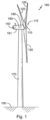
- Figure 1 illustrates a perspective view of one example of a wind turbine 160.
- the wind turbine 160 includes a tower 170 extending from a support surface 150, a nacelle 161 mounted on the tower 170, and a rotor 115 coupled to the nacelle 161.
- the rotor 115 includes a rotatable hub 110 and at least one rotor blade 120 coupled to and extending outwardly from the hub 110.
- the rotor 115 includes three rotor blades 120.
- the rotor 115 may include more or less than three rotor blades 120.
- Each rotor blade 120 may be spaced about the hub 110 to facilitate rotating the rotor 115 to enable kinetic energy to be transferred from the wind into usable mechanical energy, and subsequently, electrical energy.
- the hub 110 may be rotatably coupled to an electric generator 162 ( Figure 2 ) positioned within the nacelle 161 to permit electrical energy to be produced.
- FIG 2 illustrates a simplified, internal view of one example of the nacelle 161 of the wind turbine 160 of the Figure 1 .
- the generator 162 may be disposed within the nacelle 161.
- the generator 162 may be coupled to the rotor 115 of the wind turbine 160 for generating electrical power from the rotational energy generated by the rotor 115.
- the rotor 115 may include a main rotor shaft 163 coupled to the hub 110 for rotation therewith.
- the generator 162 may then be coupled to the rotor shaft 163 such that rotation of the rotor shaft 163 drives the generator 162.
- the generator 162 includes a generator shaft 166 rotatably coupled to the rotor shaft 163 through a gearbox 164.
- the nacelle 161 is rotatably coupled to the tower 170 through the yaw system 20 in such a way that the nacelle 161 is able to rotate about a yaw axis YA.
- the yaw system 20 comprises a yaw bearing having two bearing components configured to rotate with respect to the other.
- the tower 170 is coupled to one of the bearing components and the bedplate or support frame 165 of the nacelle 161 is coupled to the other bearing component.
- the yaw system 20 comprises an annular gear 21 and a plurality of yaw drives 22 with a motor 23, a gearbox 24 and a pinion 25 for meshing with the annular gear 21 for rotating one of the bearing components with respect to the other.
- Figures 3A - 3D schematically illustrate an example of a nacelle hatch.
- Figure 3A illustrates an isometric view of the wind turbine rotor and nacelle with a deployed hatch.
- Figure 3B illustrates the same view, wherein the hatch has been made transparent to show component.
- Figures 3C and 3D show a side view of the same nacelle and hatch.
- Figures 3E - 3G schematically illustrates a method for deploying this same nacelle hatch.
- Figure 3A illustrates an isometric view of a nacelle 161 configured to be mounted on top of a wind turbine tower.
- the nacelle 161 comprises a nacelle hatch 20 for covering a nacelle opening at a side of the nacelle facing a wind turbine hub.
- the nacelle hatch is completely supported by the nacelle 161 when the hatch is closed. This may be seen in figure 3E .
- the nacelle hatch 20 forms a passageway to an opening 30 in the wind turbine hub at a side of the wind turbine hub facing the nacelle when the hatch is opened.
- the passageway comprises a first side structure 26 at least partially obstructing a downwards view on a first side of the hub and a second side structure 26 at least partially obstructing a downwards view on a second side of the hub, the second side being opposite to the first side.
- the wind turbine has the rotor upstream from the nacelle.
- the upstream or front surface of the nacelle 63 thus faces the hub, whereas the rear surface or downstream surface of the hub faces the nacelle.
- the rotor may be arranged downstream from the nacelle.
- the nacelle may further comprises side surfaces 64 and top surface or "roof" surface 62.
- the nacelle may generally house the rotor shaft, gearbox (if present), and the generator.
- the rotor shaft may be rotatably mounted in the nacelle.
- Other components such as batteries, converters, power cables, A/C systems etc. may also be partially or completely contained within the nacelle 161.
- the nacelle hatch may be arranged vertically above the rotor shaft, or above the bearing arrangement of the rotor shaft in the nacelle.
- the nacelle hatch 20 may comprise one or more panels hingedly mounted to the nacelle for forming the passageway.
- the nacelle hatch 20 comprises a first top panel 24 hingedly mounted to the nacelle 161.
- Hinges 28 that allow rotation of the first top panel from covering an opening in the nacelle to an open position have been schematically illustrated.
- Hinges 29 have been schematically illustrated and may be seen e.g. in figures 3C and 3D .
- the nacelle hatch 20 furthermore comprises a second top panel 22 hingedly mounted at a front edge of the first top panel 24.
- Hinges 23 have been schematically illustrated in figures 3C and 3D at a front edge of the first top panel.
- a path may be provided from the nacelle to the hub.
- the side panels 26 block the view of an operator downwards on either side of the hub, and may increase security by avoiding falls on either side of the hub when stepping from the nacelle to the hub.
- Figures 3E - 3G schematically illustrate side views of an example of a method for accessing the wind turbine hub 110 from the nacelle 161.
- the wind turbine rotor Before accessing the hub, the wind turbine rotor may have been rotated to one of a plurality of predetermined positions suitable for maintenance.
- three of such positions may be predefined, e.g. the three positions corresponding to a bunny ears configuration.
- the bunny ears configuration one of the blades is pointing straight down, whereas the other blades are pointing upwards.
- the rotor may be locked in place.
- the rotor may be provided with a locking plate, and a bolt or pin may be inserted from the nacelle in a hole in the locking plate to secure the rotor in its position.
- a bolt or pin may be inserted from the nacelle in a hole in the locking plate to secure the rotor in its position.
- one of the aspects of the nacelle hatches disclosed herein is that since the nacelle hatch can be completely supported by the hub, maintenance may potentially be carried out even when the rotor is not exactly in one of the predefined stopping or locking positions.
- the method may then comprise opening a hatch 20 at a front side of the nacelle, as shown in figure 3E .
- the method then comprises deploying the hatch 20 such that the hatch 20 forms a passageway to an opening 30 in the wind turbine hub 110 at a rear side of the wind turbine hub 110.
- the passageway comprises a first side structure 26 substantially blocking a downwards view on a first side of the hub and a second side structure 26 substantially blocking a downwards view on a second side of the hub, the second side being opposite to the first side.
- the opening 30 in the wind turbine hub allowing access to the inside of the hub may be provided with a cover 35.
- cover 35 may be securely locked when in its opened position.
- Cover 35 in its opened position may be encompassed within the passageway formed by hatch 20.
- deploying the hatch 20 comprises pushing a first panel 24 hingedly mounted to the nacelle.
- the first panel 24 which is mounted to the nacelle may form a first top panel when deployed.
- the deploying of the hatch 20 may further comprise unfolding a plurality of panels 22, 26 that are hingedly mounted to the first panel 24.
- the hatch may be configured to selectively lock the panels in an opened position. This may apply to one or more or all of the panels.
- the first top panel 24 may be locked in place before unfolding the other panels. Locking of the panels may be done in a variety of ways, such as mechanically blocking with a latch or using a pneumatic or hydraulic system.
- the other panels which are suspended from the first top panel may also be locked in an open position by suitable mechanical, electrical, pneumatic or hydraulic systems.
- the hatch when opened may be supported by the hub. In other examples, the hatch, when opened, may still be fully supported by the nacelle.
- the hatch 20 may be configured to be manually opened and closed.
- An operator may in the example of figure 3 grab the first top panel and push it open. After securing the first top panel in the open position, the operator may then unfold the side panels 26 and unfold the second top panel 22.
- the procedure may be followed in opposite order.
- a system involving motors and/or pistons may be used to automatically or semi-automatically deploy the hatch when needed and also to retract the hatch.
- Figure 4 schematically illustrates a further example of a nacelle hatch 20.
- the nacelle hatch comprises a first side panel 46 hingedly mounted to the nacelle 161 for forming the first side structure, and a second side panel 46 hingedly mounted to the nacelle 161 for forming the second side structure.
- the side panels block or at least partially obstruct a downwards view of an operator wanting the access an opening 30 in the hub.
- the hatch when deployed to an open position, the operator is protected from the exterior e.g. hail, rain, wind gusts etc.
- the hatch only protects the operator on the sides, but this can be sufficient for reducing anxiety of operators.
- the first and second side panels 46 extend substantially to a top surface of the hub. I.e. the side panels 46 may be partially supported by the hub.
- the side panels are herein shown to be substantially rectangular. In other examples, the shape of the side panels may be irregular, e.g. the corners may be adapted to mate with a shape of the surface of the hub.
- Figures 5A - 5C schematically illustrates yet a further an example of a nacelle hatch.
- the nacelle hatch 50 comprises an expandable structure, which when expanded extends between an opening in the nacelle and the opening in the hub.
- the passageway formed between the nacelle and the hub may be closed on the top and on either side such that operators are generally well protected from the exterior.
- the expandable structure may comprise a bellows.
- the bellows may include a plurality of pleats 52, 54, 56, 58 which be collapsed on top of each other in the closed position of the hatch. In the open position or open configuration of the hatch 50, the pleats 52, 54, 56, 58 are separated from each other.
- the hatch 50 may include a handle which an operator may grasp to push the hatch 50 towards the hub, and/or to pull the hatch back towards the nacelle.
- opening and closing the hatch may be automatic, using e.g. an electric motor, pneumatic or hydraulic system.
- a wind turbine may comprise a tower, a nacelle arranged on top of the tower, and a rotor including a rotor hub and a plurality of wind turbine blades.
- the rotor e.g. rotor shaft
- the nacelle may comprises a nacelle opening at an upstream side of the nacelle
- the hub comprises a hub opening at a downstream side of the hub.
- the nacelle comprises a nacelle hatch, the nacelle hatch covering the nacelle opening in a first configuration, and the nacelle hatch forming a passage to the hub opening in a second configuration.
- the nacelle hatch in the second configuration includes at least a protective structure on both sides of the passage.
- a protective structure may herein be understood as any structure that increases security or protection for an operator to some extent when passing from the nacelle to the hub or vice versa.
- the protective structure may be completely secure in that an operator does not need to latch him/herself on to a safety line.
- the protective structure may be sufficiently strong and stiff for operators to use it as a support and to be able to lean against it.
- the protective structure may not be able to carry such loads but may still increase security for operators by blocking or reducing weather influences or by reducing anxiety for operators as hereinbefore explained.
- the nacelle hatch in the second configuration may include a protective structure at a top of the passage, such as shown in e.g. figures 3 and 5 .
- the nacelle hatch may comprise a plurality of unfoldable panels, such as shown in e.g. figures 3 and 4 . At least one of the plurality panels may be hingedly mounted to the nacelle.
- the nacelle hatch may comprise an expandable structure, such as shown in figure 4 .
- the expandable structure comprises a bellows, which may be a slidable bellows or corrugated bellows.
- the expandable structure may include a telescopic structure, or telescopic elements.
Landscapes
- Engineering & Computer Science (AREA)
- Life Sciences & Earth Sciences (AREA)
- Sustainable Development (AREA)
- Sustainable Energy (AREA)
- Chemical & Material Sciences (AREA)
- Combustion & Propulsion (AREA)
- Mechanical Engineering (AREA)
- General Engineering & Computer Science (AREA)
- Wind Motors (AREA)
Claims (15)
- Gondel (161), die so konfiguriert ist, dass sie oben auf einem Windturbinenturm (170) montiert werden kann, und die eine Gondelklappe (20, 50) umfasst zum Abdecken einer Gondelöffnung an einer Seite der Windturbine die einer Windturbinennabe (110) zugewandt ist, wobeidie Gondelklappe (20, 50) vollständig von der Gondel (161) getragen wird, wenn die Klappe (20, 50) geschlossen ist, unddie Gondelklappe (20, 50) so konfiguriert ist, dass sie aus einer geschlossenen Position, in der sie die Gondelöffnung abdeckt, in eine offene Position ausgefahren werden kann, in der sie einen Durchgang zu einer Öffnung (30) in der Windturbinennabe (110) auf einer der Gondel (161) zugewandten Seite der Windturbinennabe (110) bildet, wobeider Durchgang eine erste Seitenstruktur (26), die zumindest teilweise eine Sicht nach unten auf einer ersten Seite der Nabe (110) versperrt, und eine zweite Seitenstruktur (26), die zumindest teilweise eine Sicht nach unten auf einer zweiten Seite der Nabe (110) versperrt umfasst, wobei die zweite Seite der ersten Seite gegenüberliegt.
- Gondel (161) nach Anspruch 1, wobei die Gondelklappe (20, 50) eine oder mehrere Platten (24, 26) umfasst, die schwenkbar an der Gondel (161) angebracht sind, um den Durchgang zu bilden.
- Gondel (161) nach Anspruch 2, wobei die Klappe (20, 50) so konfiguriert ist, dass sie die Platten (24, 26) in einer geöffneten Position selektiv verriegelt.
- Gondel (161) nach Anspruch 2, wobei die Gondelklappe (20, 50) Folgendes umfassteine erste obere Platte (24), die schwenkbar an der Gondel (161) angebracht ist, eine erste Seitenplatte (26), die schwenkbar an der ersten oberen Platte (24) angebracht ist, um zumindest einen Teil der ersten Seitenstruktur (26) zu bilden, undeine zweite Seitenplatte (26), die schwenkbar an der ersten oberen Platte (24) angebracht ist, um zumindest einen Teil der zweiten Seitenstruktur (26) zu bilden.
- Gondel (161) nach Anspruch 4, wobei die Gondelklappe (20, 50) außerdem eine zweite obere Platte (22) umfasst, die schwenkbar an einer Vorderkante der ersten oberen Platte (24) angebracht ist.
- Gondel (161) nach Anspruch 2, wobei die Gondelklappe (20, 50) eine erste Seitenplatte (26) umfasst, die schwenkbar an der Gondel (161) angebracht ist, um die erste Seitenstruktur (26) zu bilden, und eine zweite Seitenplatte (26), die schwenkbar an der Gondel (161) angebracht ist, um die zweite Seitenstruktur (26) zu bilden.
- Gondel (161) nach Anspruch 6, wobei sich bei geöffneter Klappe (20, 50) die erste und die zweite Seitenstrukture (26) im Wesentlichen bis zu einer oberen Fläche der Nabe (110) erstrecken.
- Gondel (161) nach Anspruch 1, wobei die Gondelklappe (20, 50) eine ausdehnbare Struktur umfasst, die sich im ausgedehnten Zustand zwischen einer Öffnung in der Gondel und der Öffnung (30) in der Nabe (110) erstreckt.
- Gondel (161) nach Anspruch 8, wobei die ausdehnbare Struktur einen Faltenbalg umfasst.
- Gondel (161) nach Anspruch 1, wobei die Klappe (20, 50) so konfiguriert ist, dass sie manuell geöffnet und geschlossen werden kann.
- Gondel (161) nach Anspruch 1, wobei die Klappe (20, 50) außerdem ein hydraulisches System zum Öffnen und/oder Schließen der Klappe (20, 50) umfasst.
- Windturbine mit einem Turm und einer Gondel (161) nach Anspruch 1 auf der Spitze des Turms (170) und einer Nabe (110), die drehbar in der Gondel (161) angebracht ist.
- Verfahren für den Zugang zu einer Windturbinennabe (110) von einer Gondel (161) aus, umfassend:Öffnen einer Klappe (20, 50) an einer Vorderseite der Gondel (161) aus einer geschlossenen Position, in der die Klappe eine Öffnung in der Gondel abdeckt,Entfalten der Klappe (20, 50) aus der geschlossenen Position in eine offene Position, so dass die Klappe (20, 50) einen Durchgang zu einer Öffnung (30) in der Windturbinennabe (110) an einer Rückseite der Windturbinennabe bildet
(110), wobeider Durchgang eine erste Seitenstruktur (26) umfasst, die im Wesentlichen eine Sicht nach unten auf einer ersten Seite der Nabe (110) versperrt und einer zweiten Seitenstruktur (26), die eine Sicht nach unten auf einer zweiten Seite der Nabe (110) im Wesentlichen versperrt, wobei die zweite Seite die erste Seite gegenüberliegt. - Verfahren nach Anspruch 13, wobei das Entfalten der Klappe (20, 50)
das Schieben einer ersten Platte (24), die schwenkbar an der Gondel (161) angebracht ist, umfasst. - Verfahren nach Anspruch 14, wobei das Entfalten ferner Folgendes umfasst: Entfalten einer Vielzahl von Platten (22, 26), die gelenkig an der ersten Platte (24) befestigt sind.
Priority Applications (5)
| Application Number | Priority Date | Filing Date | Title |
|---|---|---|---|
| EP20382148.3A EP3872340B1 (de) | 2020-02-28 | 2020-02-28 | Nabenzugang durch eine gondel |
| DK20382148.3T DK3872340T3 (da) | 2020-02-28 | 2020-02-28 | Adgang til nav gennem nacelle |
| ES20382148T ES3033544T3 (en) | 2020-02-28 | 2020-02-28 | Hub access through nacelle |
| US17/184,662 US11378065B2 (en) | 2020-02-28 | 2021-02-25 | Hub access through nacelle |
| CN202110220804.2A CN113323795A (zh) | 2020-02-28 | 2021-02-26 | 通过机舱的毂通道 |
Applications Claiming Priority (1)
| Application Number | Priority Date | Filing Date | Title |
|---|---|---|---|
| EP20382148.3A EP3872340B1 (de) | 2020-02-28 | 2020-02-28 | Nabenzugang durch eine gondel |
Publications (2)
| Publication Number | Publication Date |
|---|---|
| EP3872340A1 EP3872340A1 (de) | 2021-09-01 |
| EP3872340B1 true EP3872340B1 (de) | 2025-03-26 |
Family
ID=69770842
Family Applications (1)
| Application Number | Title | Priority Date | Filing Date |
|---|---|---|---|
| EP20382148.3A Active EP3872340B1 (de) | 2020-02-28 | 2020-02-28 | Nabenzugang durch eine gondel |
Country Status (5)
| Country | Link |
|---|---|
| US (1) | US11378065B2 (de) |
| EP (1) | EP3872340B1 (de) |
| CN (1) | CN113323795A (de) |
| DK (1) | DK3872340T3 (de) |
| ES (1) | ES3033544T3 (de) |
Citations (2)
| Publication number | Priority date | Publication date | Assignee | Title |
|---|---|---|---|---|
| WO2014059994A1 (en) * | 2012-10-19 | 2014-04-24 | Vestas Wind Systems A/S | A wind turbine |
| EP2568162B1 (de) * | 2011-09-07 | 2015-12-23 | Nordex Energy GmbH | Windenergieanlage mit einer auf einem Turm angeordneten Gondel mit einem Übergang vom Dach der Gondel in den Rotor |
Family Cites Families (11)
| Publication number | Priority date | Publication date | Assignee | Title |
|---|---|---|---|---|
| US7845693B2 (en) | 2008-10-10 | 2010-12-07 | General Electric Company | Hatch stop for wind turbines |
| US8061999B2 (en) | 2008-11-21 | 2011-11-22 | General Electric Company | Spinner-less hub access and lifting system for a wind turbine |
| JP2011032965A (ja) | 2009-08-04 | 2011-02-17 | Mitsubishi Heavy Ind Ltd | ハッチカバー装置 |
| ES2594232T3 (es) | 2010-12-27 | 2016-12-16 | Areva Wind Gmbh | Tapa de compuerta para una planta de energía eólica |
| US8807923B2 (en) * | 2011-02-07 | 2014-08-19 | Vestas Wind Systems A/S | Access apparatus for a wind turbine and method of using same |
| DK2673499T3 (en) * | 2011-02-07 | 2017-12-04 | Mhi Vestas Offshore Wind As | WINDMILL WITH HELIP PLATFORM DEVICE AND PROCEDURE FOR USING THE SAME |
| US9115698B2 (en) * | 2012-03-06 | 2015-08-25 | General Electric Company | Wind turbine with access features for gaining access to the interior of a rotor hub |
| CN203246979U (zh) * | 2013-01-24 | 2013-10-23 | 中建一局集团第二建筑有限公司 | 施工电梯大过桥翻板通道装置 |
| ES2798928T3 (es) * | 2016-04-15 | 2020-12-14 | Vestas Wind Sys As | Turbina eólica multirrotor con una plataforma |
| US10982659B2 (en) * | 2016-09-21 | 2021-04-20 | Vestas Wind Systems A/S | Method for opening a cover portion of a wind turbine |
| EP3372824A1 (de) * | 2017-03-07 | 2018-09-12 | Adwen GmbH | Gondelabdeckung für windturbinen |
-
2020
- 2020-02-28 DK DK20382148.3T patent/DK3872340T3/da active
- 2020-02-28 EP EP20382148.3A patent/EP3872340B1/de active Active
- 2020-02-28 ES ES20382148T patent/ES3033544T3/es active Active
-
2021
- 2021-02-25 US US17/184,662 patent/US11378065B2/en active Active
- 2021-02-26 CN CN202110220804.2A patent/CN113323795A/zh active Pending
Patent Citations (3)
| Publication number | Priority date | Publication date | Assignee | Title |
|---|---|---|---|---|
| EP2568162B1 (de) * | 2011-09-07 | 2015-12-23 | Nordex Energy GmbH | Windenergieanlage mit einer auf einem Turm angeordneten Gondel mit einem Übergang vom Dach der Gondel in den Rotor |
| WO2014059994A1 (en) * | 2012-10-19 | 2014-04-24 | Vestas Wind Systems A/S | A wind turbine |
| US20150267685A1 (en) * | 2012-10-19 | 2015-09-24 | Vestas Wind Systems A/S | Wind turbine |
Also Published As
| Publication number | Publication date |
|---|---|
| ES3033544T3 (en) | 2025-08-05 |
| US20210270245A1 (en) | 2021-09-02 |
| DK3872340T3 (da) | 2025-06-23 |
| US11378065B2 (en) | 2022-07-05 |
| CN113323795A (zh) | 2021-08-31 |
| EP3872340A1 (de) | 2021-09-01 |
Similar Documents
| Publication | Publication Date | Title |
|---|---|---|
| JP4335214B2 (ja) | ローターブレード取付け方法および風力タービン用のローターブレード | |
| EP2604851B1 (de) | Windturbinen-Gondelabdeckung und Verfahren zum Installieren eines Generators auf einem Hauptrahmen in einer Gondel | |
| EP2635804B1 (de) | Windenergieanlage | |
| EP2291585B1 (de) | Nabengehäuse für die nabe einer windturbine | |
| US10982659B2 (en) | Method for opening a cover portion of a wind turbine | |
| EP2447524A1 (de) | Gehäusesystem für eine Windturbinenwinkelverstellungsanordnung | |
| EP2192297A2 (de) | Kreiselfreier Nabenzugriff und Hebesystem für eine Windturbine | |
| EP2570653B1 (de) | Wandelbare Abdeckung für Windturbinengondel | |
| EP3443221B1 (de) | Multirotorwindturbine mit einer plattform | |
| WO2012013636A1 (en) | Nacelle for a wind turbine | |
| WO2021180290A1 (en) | A yaw system for a multiple rotor wind turbine | |
| US20210222680A1 (en) | System and method for repairing a gearbox of a wind turbine uptower | |
| US11378065B2 (en) | Hub access through nacelle | |
| US10570888B2 (en) | Working platform within a nacelle of a wind turbine | |
| CN112983763B (zh) | 防止人员暴露于由风力涡轮表面限定的开口的组件和方法 | |
| EP3431757B1 (de) | Externe plattformanordnung für windturbinenreparaturen | |
| EP2920456B1 (de) | Windturbinenanlage mit turmkonsole | |
| US12497951B2 (en) | Cabins and methods for wind turbine maintenance |
Legal Events
| Date | Code | Title | Description |
|---|---|---|---|
| PUAI | Public reference made under article 153(3) epc to a published international application that has entered the european phase |
Free format text: ORIGINAL CODE: 0009012 |
|
| STAA | Information on the status of an ep patent application or granted ep patent |
Free format text: STATUS: THE APPLICATION HAS BEEN PUBLISHED |
|
| AK | Designated contracting states |
Kind code of ref document: A1 Designated state(s): AL AT BE BG CH CY CZ DE DK EE ES FI FR GB GR HR HU IE IS IT LI LT LU LV MC MK MT NL NO PL PT RO RS SE SI SK SM TR |
|
| STAA | Information on the status of an ep patent application or granted ep patent |
Free format text: STATUS: REQUEST FOR EXAMINATION WAS MADE |
|
| 17P | Request for examination filed |
Effective date: 20220301 |
|
| RBV | Designated contracting states (corrected) |
Designated state(s): AL AT BE BG CH CY CZ DE DK EE ES FI FR GB GR HR HU IE IS IT LI LT LU LV MC MK MT NL NO PL PT RO RS SE SI SK SM TR |
|
| P01 | Opt-out of the competence of the unified patent court (upc) registered |
Effective date: 20230530 |
|
| STAA | Information on the status of an ep patent application or granted ep patent |
Free format text: STATUS: EXAMINATION IS IN PROGRESS |
|
| 17Q | First examination report despatched |
Effective date: 20240215 |
|
| GRAP | Despatch of communication of intention to grant a patent |
Free format text: ORIGINAL CODE: EPIDOSNIGR1 |
|
| STAA | Information on the status of an ep patent application or granted ep patent |
Free format text: STATUS: GRANT OF PATENT IS INTENDED |
|
| INTG | Intention to grant announced |
Effective date: 20240925 |
|
| GRAS | Grant fee paid |
Free format text: ORIGINAL CODE: EPIDOSNIGR3 |
|
| GRAA | (expected) grant |
Free format text: ORIGINAL CODE: 0009210 |
|
| STAA | Information on the status of an ep patent application or granted ep patent |
Free format text: STATUS: THE PATENT HAS BEEN GRANTED |
|
| AK | Designated contracting states |
Kind code of ref document: B1 Designated state(s): AL AT BE BG CH CY CZ DE DK EE ES FI FR GB GR HR HU IE IS IT LI LT LU LV MC MK MT NL NO PL PT RO RS SE SI SK SM TR |
|
| REG | Reference to a national code |
Ref country code: GB Ref legal event code: FG4D |
|
| REG | Reference to a national code |
Ref country code: CH Ref legal event code: EP |
|
| REG | Reference to a national code |
Ref country code: DE Ref legal event code: R096 Ref document number: 602020048260 Country of ref document: DE |
|
| REG | Reference to a national code |
Ref country code: IE Ref legal event code: FG4D |
|
| REG | Reference to a national code |
Ref country code: DK Ref legal event code: T3 Effective date: 20250617 |
|
| PG25 | Lapsed in a contracting state [announced via postgrant information from national office to epo] |
Ref country code: RS Free format text: LAPSE BECAUSE OF FAILURE TO SUBMIT A TRANSLATION OF THE DESCRIPTION OR TO PAY THE FEE WITHIN THE PRESCRIBED TIME-LIMIT Effective date: 20250626 |
|
| PG25 | Lapsed in a contracting state [announced via postgrant information from national office to epo] |
Ref country code: FI Free format text: LAPSE BECAUSE OF FAILURE TO SUBMIT A TRANSLATION OF THE DESCRIPTION OR TO PAY THE FEE WITHIN THE PRESCRIBED TIME-LIMIT Effective date: 20250326 |
|
| REG | Reference to a national code |
Ref country code: LT Ref legal event code: MG9D |
|
| PG25 | Lapsed in a contracting state [announced via postgrant information from national office to epo] |
Ref country code: NO Free format text: LAPSE BECAUSE OF FAILURE TO SUBMIT A TRANSLATION OF THE DESCRIPTION OR TO PAY THE FEE WITHIN THE PRESCRIBED TIME-LIMIT Effective date: 20250626 |
|
| PG25 | Lapsed in a contracting state [announced via postgrant information from national office to epo] |
Ref country code: HR Free format text: LAPSE BECAUSE OF FAILURE TO SUBMIT A TRANSLATION OF THE DESCRIPTION OR TO PAY THE FEE WITHIN THE PRESCRIBED TIME-LIMIT Effective date: 20250326 |
|
| PG25 | Lapsed in a contracting state [announced via postgrant information from national office to epo] |
Ref country code: LV Free format text: LAPSE BECAUSE OF FAILURE TO SUBMIT A TRANSLATION OF THE DESCRIPTION OR TO PAY THE FEE WITHIN THE PRESCRIBED TIME-LIMIT Effective date: 20250326 |
|
| PG25 | Lapsed in a contracting state [announced via postgrant information from national office to epo] |
Ref country code: GR Free format text: LAPSE BECAUSE OF FAILURE TO SUBMIT A TRANSLATION OF THE DESCRIPTION OR TO PAY THE FEE WITHIN THE PRESCRIBED TIME-LIMIT Effective date: 20250627 Ref country code: BG Free format text: LAPSE BECAUSE OF FAILURE TO SUBMIT A TRANSLATION OF THE DESCRIPTION OR TO PAY THE FEE WITHIN THE PRESCRIBED TIME-LIMIT Effective date: 20250326 |
|
| REG | Reference to a national code |
Ref country code: NL Ref legal event code: MP Effective date: 20250326 |
|
| REG | Reference to a national code |
Ref country code: ES Ref legal event code: FG2A Ref document number: 3033544 Country of ref document: ES Kind code of ref document: T3 Effective date: 20250805 |
|
| PG25 | Lapsed in a contracting state [announced via postgrant information from national office to epo] |
Ref country code: NL Free format text: LAPSE BECAUSE OF FAILURE TO SUBMIT A TRANSLATION OF THE DESCRIPTION OR TO PAY THE FEE WITHIN THE PRESCRIBED TIME-LIMIT Effective date: 20250326 |
|
| PG25 | Lapsed in a contracting state [announced via postgrant information from national office to epo] |
Ref country code: SE Free format text: LAPSE BECAUSE OF FAILURE TO SUBMIT A TRANSLATION OF THE DESCRIPTION OR TO PAY THE FEE WITHIN THE PRESCRIBED TIME-LIMIT Effective date: 20250326 |
|
| REG | Reference to a national code |
Ref country code: AT Ref legal event code: MK05 Ref document number: 1779202 Country of ref document: AT Kind code of ref document: T Effective date: 20250326 |
|
| PG25 | Lapsed in a contracting state [announced via postgrant information from national office to epo] |
Ref country code: SM Free format text: LAPSE BECAUSE OF FAILURE TO SUBMIT A TRANSLATION OF THE DESCRIPTION OR TO PAY THE FEE WITHIN THE PRESCRIBED TIME-LIMIT Effective date: 20250326 |
|
| PG25 | Lapsed in a contracting state [announced via postgrant information from national office to epo] |
Ref country code: PT Free format text: LAPSE BECAUSE OF FAILURE TO SUBMIT A TRANSLATION OF THE DESCRIPTION OR TO PAY THE FEE WITHIN THE PRESCRIBED TIME-LIMIT Effective date: 20250728 |
|
| PG25 | Lapsed in a contracting state [announced via postgrant information from national office to epo] |
Ref country code: IT Free format text: LAPSE BECAUSE OF FAILURE TO SUBMIT A TRANSLATION OF THE DESCRIPTION OR TO PAY THE FEE WITHIN THE PRESCRIBED TIME-LIMIT Effective date: 20250326 Ref country code: PL Free format text: LAPSE BECAUSE OF FAILURE TO SUBMIT A TRANSLATION OF THE DESCRIPTION OR TO PAY THE FEE WITHIN THE PRESCRIBED TIME-LIMIT Effective date: 20250326 |
|
| PG25 | Lapsed in a contracting state [announced via postgrant information from national office to epo] |
Ref country code: AT Free format text: LAPSE BECAUSE OF FAILURE TO SUBMIT A TRANSLATION OF THE DESCRIPTION OR TO PAY THE FEE WITHIN THE PRESCRIBED TIME-LIMIT Effective date: 20250326 |
|
| PG25 | Lapsed in a contracting state [announced via postgrant information from national office to epo] |
Ref country code: EE Free format text: LAPSE BECAUSE OF FAILURE TO SUBMIT A TRANSLATION OF THE DESCRIPTION OR TO PAY THE FEE WITHIN THE PRESCRIBED TIME-LIMIT Effective date: 20250326 |
|
| PG25 | Lapsed in a contracting state [announced via postgrant information from national office to epo] |
Ref country code: RO Free format text: LAPSE BECAUSE OF FAILURE TO SUBMIT A TRANSLATION OF THE DESCRIPTION OR TO PAY THE FEE WITHIN THE PRESCRIBED TIME-LIMIT Effective date: 20250326 |
|
| PG25 | Lapsed in a contracting state [announced via postgrant information from national office to epo] |
Ref country code: SK Free format text: LAPSE BECAUSE OF FAILURE TO SUBMIT A TRANSLATION OF THE DESCRIPTION OR TO PAY THE FEE WITHIN THE PRESCRIBED TIME-LIMIT Effective date: 20250326 |
|
| PG25 | Lapsed in a contracting state [announced via postgrant information from national office to epo] |
Ref country code: IS Free format text: LAPSE BECAUSE OF FAILURE TO SUBMIT A TRANSLATION OF THE DESCRIPTION OR TO PAY THE FEE WITHIN THE PRESCRIBED TIME-LIMIT Effective date: 20250726 |
|
| REG | Reference to a national code |
Ref country code: DE Ref legal event code: R097 Ref document number: 602020048260 Country of ref document: DE |
|
| PG25 | Lapsed in a contracting state [announced via postgrant information from national office to epo] |
Ref country code: CZ Free format text: LAPSE BECAUSE OF FAILURE TO SUBMIT A TRANSLATION OF THE DESCRIPTION OR TO PAY THE FEE WITHIN THE PRESCRIBED TIME-LIMIT Effective date: 20250326 |
|
| PLBE | No opposition filed within time limit |
Free format text: ORIGINAL CODE: 0009261 |
|
| STAA | Information on the status of an ep patent application or granted ep patent |
Free format text: STATUS: NO OPPOSITION FILED WITHIN TIME LIMIT |
|
| REG | Reference to a national code |
Ref country code: CH Ref legal event code: L10 Free format text: ST27 STATUS EVENT CODE: U-0-0-L10-L00 (AS PROVIDED BY THE NATIONAL OFFICE) Effective date: 20260211 |
|
| 26N | No opposition filed |
Effective date: 20260105 |
|
| PGFP | Annual fee paid to national office [announced via postgrant information from national office to epo] |
Ref country code: ES Payment date: 20260302 Year of fee payment: 7 |
|
| PGFP | Annual fee paid to national office [announced via postgrant information from national office to epo] |
Ref country code: DE Payment date: 20260121 Year of fee payment: 7 Ref country code: DK Payment date: 20260121 Year of fee payment: 7 |