EP3871977B1 - Automatische flugzeugpilotensitz-seitenstangenarmlehne - Google Patents
Automatische flugzeugpilotensitz-seitenstangenarmlehne Download PDFInfo
- Publication number
- EP3871977B1 EP3871977B1 EP21160040.8A EP21160040A EP3871977B1 EP 3871977 B1 EP3871977 B1 EP 3871977B1 EP 21160040 A EP21160040 A EP 21160040A EP 3871977 B1 EP3871977 B1 EP 3871977B1
- Authority
- EP
- European Patent Office
- Prior art keywords
- armrest
- subframe
- frame
- coupled
- relative
- Prior art date
- Legal status (The legal status is an assumption and is not a legal conclusion. Google has not performed a legal analysis and makes no representation as to the accuracy of the status listed.)
- Active
Links
Images


Classifications
-
- B—PERFORMING OPERATIONS; TRANSPORTING
- B64—AIRCRAFT; AVIATION; COSMONAUTICS
- B64D—EQUIPMENT FOR FITTING IN OR TO AIRCRAFT; FLIGHT SUITS; PARACHUTES; ARRANGEMENT OR MOUNTING OF POWER PLANTS OR PROPULSION TRANSMISSIONS IN AIRCRAFT
- B64D11/00—Passenger or crew accommodation; Flight-deck installations not otherwise provided for
- B64D11/06—Arrangements of seats, or adaptations or details specially adapted for aircraft seats
- B64D11/0639—Arrangements of seats, or adaptations or details specially adapted for aircraft seats with features for adjustment or converting of seats
- B64D11/0644—Adjustable arm rests
-
- B—PERFORMING OPERATIONS; TRANSPORTING
- B64—AIRCRAFT; AVIATION; COSMONAUTICS
- B64D—EQUIPMENT FOR FITTING IN OR TO AIRCRAFT; FLIGHT SUITS; PARACHUTES; ARRANGEMENT OR MOUNTING OF POWER PLANTS OR PROPULSION TRANSMISSIONS IN AIRCRAFT
- B64D11/00—Passenger or crew accommodation; Flight-deck installations not otherwise provided for
- B64D11/06—Arrangements of seats, or adaptations or details specially adapted for aircraft seats
- B64D11/0646—Seats characterised by special features of stationary arms, foot or head rests
-
- B—PERFORMING OPERATIONS; TRANSPORTING
- B64—AIRCRAFT; AVIATION; COSMONAUTICS
- B64D—EQUIPMENT FOR FITTING IN OR TO AIRCRAFT; FLIGHT SUITS; PARACHUTES; ARRANGEMENT OR MOUNTING OF POWER PLANTS OR PROPULSION TRANSMISSIONS IN AIRCRAFT
- B64D11/00—Passenger or crew accommodation; Flight-deck installations not otherwise provided for
- B64D11/06—Arrangements of seats, or adaptations or details specially adapted for aircraft seats
- B64D11/0689—Arrangements of seats, or adaptations or details specially adapted for aircraft seats specially adapted for pilots
Definitions
- a side-stick, or sidestick controller is an aircraft control joystick located on a side console in a cockpit that is typically configured to control one or more aspects of the control of the aircraft. Pilot seats often have armrest adjustment capability to allow the pilot to comfortably and accurately make adjustments to the side-stick. It is often difficult to adjust the movements on the existing pilot seat side-stick armrests. Adjustment of existing pilot seat side-stick armrests usually requires spinning knobs multiple times to achieve the proper armrest orientation necessary for the pilot to have their arm positioned correctly to the aircraft side-stick mounted to the cock-pit console. The adjustment process is complicated enough for some side-stick armrests to have dial indicators to help the pilot achieve their optimum arm to side-stick position. Therefore, it would be advantageous to provide a solution that cures the shortcomings described above. An armrest assembly is disclosed in DE 10 2005 006977 and in US 8 333 432 B2 .
- An armrest is provided as defined by claim 1.
- the pushrod is configured to releasably lock at more than one position of extension.
- the armrest is configured to manually pivot relative to the armrest frame.
- rail lock actuator is configured as a friction lock.
- the rail lock actuator is configured to lock the arm pad into a plurality of translation positions relative to the armrest subframe.
- the arm pad is configured to translate manually relative to the armrest subframe.
- the rotation mechanism is configured to releasably lock into a plurality of rotation positions relative to the seat frame.
- the rotation mechanism further includes a rotation input actuator configured to at least one of lock the armrest subframe into or release the armrest from the plurality of rotation positions.
- An aircraft seat is also provided as defined by claim 9.
- a letter following a reference numeral is intended to reference an embodiment of the feature or element that may be similar, but not necessarily identical, to a previously described element or feature bearing the same reference numeral (e.g., 1, 1a, 1b).
- reference numeral e.g. 1, 1a, 1b
- Such shorthand notations are used for purposes of convenience only and should not be construed to limit the disclosure in any way unless expressly stated to the contrary.
- any reference to “one embodiment” or “some embodiments” means that a particular element, feature, structure, or characteristic described in connection with the embodiment is included in at least one embodiment disclosed herein.
- An armrest for a seat is disclosed. Specifically, an armrest for a pilot seat of a cockpit is disclosed. More particularly, the armrest is capable of pivoting, extending. Retracting, and raising/lowering relative to the passenger seat via three separate adjustment mechanism. These adjustment mechanisms are configured to give pilots greater comfort and control when operating an aircraft, particularly when operating a side-stick.
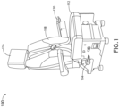
- FIG. 1 is an example environment of an aircraft seat 100, in accordance with one or more embodiments of the present disclosure.
- the aircraft seat 100 includes a seat frame 104, a seat back 108, a seat pan 112, a headrest 116.
- the aircraft seat also includes at least one armrest 120 having multiple adjustment capabilities as described herein.
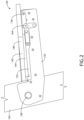
- FIG. 2 is a side view of the armrest 120 attached to the seat frame 104, in accordance with one or more embodiments of the disclosure.
- the armrest 120 includes an armrest frame 124.
- the armrest frame 124 pivotably couples at a first end to the seat frame 104.
- the armrest frame 124 also attaches to other components of the armrest 120.
- the armrest 120 further includes an armrest joint 128 for rotationally coupling to the seat frame 104.
- the armrest joint 128 is configured to allow the armrest to pivot relative to the seat frame 104 when the armrest 120 is attached to the seat frame 104.
- the armrest 120 further includes an armrest subframe 132 coupled to the armrest frame 124 at a pivot point 136.
- the armrest is configured pivotably coupled to the armrest frame via the pivot point 136 (e.g., the pivot point allows the armrest subframe 132 to tilt relative to the armrest frame 124).
- the armrest 120 includes an arm pad 140 disposed upon the armrest subframe 132.
- the arm pad 120 may be of any type or size of support structure for the arm and may consist of one or more layers (e.g., a comfort layer 142 and/or a structure layer 144).
- the arm pad 140 is laterally aligned with and translatable coupled to the armrest subframe 132.
- the arm pad 140 in a retracted position, may cover the entirety of the armrest subframe 132.
- the arm pad 140 may be extended relative to the armrest subframe (e.g., as shown in FIG. 4 ).
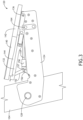
- FIG. 3 is a side view of the armrest 120 attached to the seat frame 104 with the armrest subframe 132 in a tilted configuration, in accordance with one or more embodiments of the disclosure.
- the armrest subframe 132 is tilted, or pivoted, relative to the armrest frame 124 via a tilting mechanism configured to lock the armrest subframe 132 into a plurality of tilting positions relative to the armrest frame 124, allowing an infinite number of tilt angles or tilt positions between the armrest subframe 132 and the armrest frame.
- the titling mechanism is configured to control the tilt of the armrest subframe relative to the armrest frame.
- the armrest 120 includes a tilting mechanism based on a spring-loaded apparatus (e.g., motion of the tilting mechanism is powered via a spring).
- the tilting mechanism includes a first moveable member 152 pivotably coupled to one end of the armrest subframe 132 (e.g., via a simple hinge joint).
- the first moveable member 152 is coupled to the end of the armrest subframe opposite of the pivot point 136.
- the tilting mechanism also includes a second moveable member 156 pivotably coupled on one end to the armrest frame 124 or armrest frame-attached component, and pivotably coupled to the first moveable member 152 (e.g., via a hinge.)
- the tilting mechanism also includes a pushrod 157 coupled to a collar 158, which is coupled to a shaft 159.
- the pushrod 157 is coupled to the connection point of the first movable member 152 and the second moveable member 156 at the point where both members are coupled (e.g., at the hinge joint).
- the movement of the pushrod 157 actuates the first moveable member 152 and the second moveable member 156, altering the tilt angle of the armrest subframe 132 relative to the armrest frame 124.
- the shaft having a motive force pushed against it by a spring or other biasing unit, pushes upon the pushrod 157 (e.g., aided and/or aligned by the collar), resulting in an extension of the pushrod and an increased distance between the opening between the armrest subframe 132 and the armrest frame 124.
- a spring within the shaft applies a biasing force against the pushrod.
- Compression springs are also attached to the first moveable member 152, the second moveable member 146 or the pushrod are utilized to provide a force alter the angle of the armrest subframe 132 relative to the armrest frame 124.
- the tilt input actuator 164 includes a default lock setting that prevents movement of the armrest subframe, thereby preventing any change in tilt, wherein manual pressing of a button on the tilt input actuator 164 releases the lock setting and allows pivoting movement of the armrest subframe (e.g., via the springs).
- the armrest 120 may utilize any type of lock/unlock mechanism.
- the tilt input actuator 164 may be mechanically coupled to a friction-type locking mechanism consisting of a rod coupled to the second moving member 156 and the armrest frame 124, with a coupler translatably or slidably coupled to the rod and affixed and mechanically coupled to the tilt input actuator 164.
- a locking element presses a locking portion of the coupler against the rod, holding the armrest in a tilt position.
- the button associated with the tilt input actuator 164 the locking portion is released from the rod, and the tilting of the armrest subframe may be adjusted by the biasing spring or adjusted manually by pushing on the armrest subframe 132 or arm pad 140.
- the tilt mechanism is configured to adjust the armrest 120 to an unlimited number of tilt positions.
- the tilt mechanism may be configured to adjust the armrest subframe to tilt to from any position approximately parallel to the armrest frame 104 to approximately 15° relative to the armrest frame.
- the tilt mechanism may be configured to adjust the armrest subframe to tilt to from any position approximately parallel to the armrest frame 104 to approximately 20° relative to the armrest frame.
- the tilt mechanism may be configured to adjust the armrest subframe to tilt to from any position approximately parallel to the armrest frame 104 to approximately 30° relative to the armrest frame.
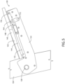
- FIG. 4 is a side view of the armrest 120 attached to the seat frame 104 with the arm pad 140 (e.g., the comfort layer 142 and the structure layer 144) configured in a translated, or extended, position relative to the armrest subframe 132, in accordance with one or more embodiments of the disclosure.
- the arm pad 140 is configured to slide along the armrest subframe 132 while still maintaining lateral alignment with the armrest subframe.
- the sliding of the arm pad 140 along the armrest subframe 132 may involve any sliding technology.
- the arm pad 140 may be configured to slide along the armrest subframe 132 within a grooved channel or other surface (e.g., the arm pad 140 and armrest subframe 132 may be arranged in a tongue and groove, rail and stile, or similar arrangement).
- the arm pad 140 and/or armrest subframe 132 may also include one or more bearings to facilitate the sliding of the arm pad 140 along the armrest subframe 132.
- the armrest includes a rail lock actuator 168 coupled to the armrest frame and configured to releasably interact with the rail.
- the rail lock actuator may be configured to lock the arm pad 140 into an unlimited number of translation positions.
- the rail lock actuator 168 may configured as any type of releasable locking mechanism.
- the rail lock actuator 168 may be configured as a friction lock.
- the rail lock actuator 168 may be configured as a biasing unit coupled to the armrest subframe 132 that biases against the structure layer 144 (e.g., a rail or rail-like section of the structure layer 144) of the arm pad 140.
- the biasing unit may include a spring.
- the pressing of a button on the rail lock actuator 168 may release the biasing unit, allowing the arm pad 140 to be manually positioned in one of a plurality of translation positions (e.g., the rail lock actuator 168 is configured to releasably interact with the rail of the structure layer 144).
- the arm pad 140 Upon release of the button for the rail lock actuator, the arm pad 140 is locked into the translation position.
- the arm pad 140 may be translated relative to the arm subframe 132 via a biasing member, such as a spring.
- FIG. 5 is an illustration a side view of the armrest attached to the seat frame 104 with the armrest 120 in a pivoted position (e.g., upward tilted position) relative to the seat frame 104 in accordance with one or more embodiments of the disclosure.
- the armrest 120 may be configured to rotate with any degree of freedom.
- the armrest 120 may be configured to rotate 360° relative to the seat frame 104 (e.g., the armrest 120 may be configured to rotate in a complete circle).
- the armrest 120 may be configured to rotate 90° relative to the seat frame 104.
- the armrest 120 may be configured to rotate 45° clockwise and counter clockwise from an initial position relative to the seat frame 104 when the armrest 120 at the initial position is positioned parallel to a floor that the seat frame 104 sits upon.
- the armrest 120 may be configured to rotate 30° relative to the seat frame 104.
- the armrest 120 may be configured to rotate 15° relative to the seat frame 104.
- the armrest is configured with a rotation mechanism coupled to the seat frame 104 and the armrest 120, and configured to rotate the armrest 120 (e.g., armrest frame 124) relative to the seat frame 104.
- the rotation mechanism may be configured with a biasing mechanism that biases the armrest 120 towards a rotation position.
- the rotation mechanism includes a spring-loaded linkage. Any type of spring-loaded linkage may be utilized by the rotation mechanism.
- the spring-loaded linkage may include a rotational spring associated with the armrest joint 128 configured to bias the armrest 120 towards a raised position relative to the seat frame 104.
- the spring-loaded linkage may include one or more extension springs coupled to the armrest 120 and the seat frame 104.
- the rotation mechanism further includes a rotation input activator 172 coupled to the armrest frame 124 configured to lock the armrest frame 124 into one of a plurality of rotation positions and/or release the armrest frame 124 from one of the plurality of rotation positions.
- the rotation input actuator 172 may have a default lock setting that prevents movement of the armrest subframe, thereby preventing any change in rotation.
- manual pressing of a button on the rotation input actuator 172 e.g., shown as a circle in FIG. 5
- the armrest 120 may utilize any type of lock/unlock mechanism.
- the rotation input actuator 172 may be mechanically coupled to a friction-type locking mechanism consisting of a rod coupled to the seat frame 104 and/or armrest joint 128 and the armrest frame 124, with a coupler translatably or slidably coupled to the rod and affixed and mechanically coupled to the rotation input actuator 172.
- a friction-type locking mechanism consisting of a rod coupled to the seat frame 104 and/or armrest joint 128 and the armrest frame 124, with a coupler translatably or slidably coupled to the rod and affixed and mechanically coupled to the rotation input actuator 172.
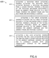
- FIG. 6 is a flowchart illustrating a method 600 for adjusting the armrest 120, which is not part of the scope of the claims.
- the method 600 includes one or more steps for adjusting the rotation of the armrest frame 124 relative to the seat frame 104, the tilting or pivoting of the armrest subframe 132 relative to the armrest frame 124, and the translation (e.g., extension and/or retraction) of the arm pad 140 relative to the armrest subframe 132.
- the method 600 includes a step 610 of actuating the rotation input actuator 172, wherein actuating the rotation input actuator 172 releases a rotation mechanism from a locked rotation position, wherein a release of the rotation mechanism rotationally biases the armrest frame 124 relative to the seat frame 104, wherein the armrest frame 124 and the seat frame 104 are rotationally coupled.
- a user may push a button associated with the rotation input actuator 172, releasing the armrest frame 124 from a locked position of rotation, and allowing a biasing spring within the rotation mechanism to rotate the armrest frame 124 to a different rotation position relative to the seat frame 104.
- the rotation input actuator 172 may be configured such that deactivating the rotation input actuator 172 (e.g., by releasing the button associated with the rotation input actuator 172) relocks the rotation mechanism.
- the method 600 includes a step 620 of actuating the tilt input actuator 164, wherein actuating the tilt input actuator 164 releases a tilting mechanism from a locked tilt position, wherein a release of the tilting mechanism pivotably biases an armrest subframe 132 relative to the armrest frame 124, wherein the armrest subframe 132 and the armrest frame 124 are pivotably coupled.
- a user may push a button associated with the tilt input actuator 164, releasing the armrest subframe 132 from a locked tilt position, and allowing a biasing spring within the tilting mechanism to pivot the armrest subframe 132 to a different tilt position relative to the armrest frame 124.
- the tilt input actuator 164 may be configured such that deactivating the tilt input actuator 164 (e.g., by releasing the button associated with the tilt input actuator 164) relocks the tilting mechanism.
- the method includes a step 630 of actuating the rail lock actuator 168, wherein actuating the rail lock actuator 168 releases the arm pad 140 from a locked position relative to the armrest subframe 132, wherein the arm pad 140 is laterally aligned with and translatably coupled to the armrest subframe 132.
- the user may push a button associated with the rail lock actuator 168, releasing the arm pad 140 from a locked translated position relative to the armrest subframe 132.
- the rail lock activator 168 may be configured such that deactivating the rail lock actuator (e.g., by releasing the button associated with the rail lock actuator 168) relocks the arm pad 140 into a locked position relative to the rail subframe 132.
- the arm pad 140 may be translated relative to the arm subframe 132 via a biasing member, such as a spring.
- the method 600 includes a step 640 of manually rotating the armrest frame 104 relative to the seat frame 104 and deactivating the rotation input actuator 172.
- the user may press down in the arm pad 140 (e.g., countering the biasing action of the rotation mechanism) and adjust the rotation of the armrest 120 to the desired position.
- the rotation input actuator 172 e.g., by releasing the button associated with the rotation input actuator 172
- the armrest 120 relocks into a rotation position.
- the method includes a step 650 of manually pivoting the armrest subframe 132 relative to the armrest frame 124 and deactivating the tilt input actuator 164.
- the user may press down on the arm pad 140 (e.g., countering the biasing action of the tilting mechanism) and adjust the tilt of the arm pad 140 to the desired position.
- the tilt input actuator 164 e.g., by releasing the button associated with the tilt input actuator 164
- the armrest subframe 132 relocks into a tilt position.
- the method includes a step 660 of manually translating the arm pad relative to the armrest subframe, and deactivating the rail lock actuator. For example, while pressing the button associated with the rail lock actuator 168, the user may lightly press down on the arm pad 140 and push the arm pad 140 to extend or retract relative to the armrest subframe 132 to the desired position. Upon deactivation of the rail lock actuator (e.g., by release the button associated with the rail lock actuator 168), the arm pad 140 locks into a translate position relative to the armrest subframe.
- the arm pad 140 may be placed into any one of an unlimited number of rotation, pivot/tilt and extension/retraction positions, enabling the user to comfortably rest their arm.
- Components illustrated and described herein are merely examples of a system/device and components that may be used to implement embodiments of the inventive concepts and may be replaced with other devices and components without departing from the scope of the claims.
- any dimensions, degrees, and/or numerical ranges provided herein are to be understood as non-limiting examples unless otherwise specified in the claims.
Landscapes
- Engineering & Computer Science (AREA)
- Aviation & Aerospace Engineering (AREA)
- Seats For Vehicles (AREA)
Claims (9)
- Armlehne, umfassend:einen Armlehnenrahmen (124), der an einem ersten Ende drehbar an einen Sitzrahmen koppelbar ist;einen Armlehnen-Teilrahmen (132), der schwenkbar an ein zweites Ende des Armlehnenrahmens gekoppelt ist, wobei der Armlehnen-Teilrahmen an einem Schwenkpunkt (136) an den Armlehnenrahmen gekoppelt ist;ein Armpolster (140), das lateral ausgerichtet und verschiebbar an den Armlehnen-Teilrahmen gekoppelt ist, umfassend eine Konstruktionsschicht (144), wobei die Konstruktionsschicht eine Schiene umfasst;einen Kippmechanismus, der zum Schwenken des Armlehnen-Teilrahmens relativ zu dem Armlehnenrahmen konfiguriert ist, umfassend:ein erstes bewegliches Element (152), das schwenkbar an den Armlehnen-Teilrahmen gekoppelt ist,ein zweites bewegliches Element (156), das schwenkbar an den Armlehnenrahmen und mechanisch an das erste bewegliche Element gekoppelt ist;eine Druckstange (157), die an einem Verbindungspunkt an das erste bewegliche Element und das zweite bewegliche Element gekoppelt ist;eine Welle (159), die an einem ersten Ende über einen Ring (158) mechanisch an die Druckstange (157) und an mindestens einen von dem Armlehnenrahmen oder Armlehnen-Teilrahmen gekoppelt ist, wobei ein Ausfahren der Druckstange die Neigung des Armlehnen-Teilrahmens relativ zu dem Armlehnenrahmen vergrö-ßert;eine Druckfeder, die mechanisch an mindestens eines von dem ersten beweglichen Element, dem zweiten beweglichen Element oder der Druckstange gekoppelt und zum Vorspannen der Druckstange in Richtung des Ausfahrens konfiguriert ist;einen Neigungseingabeaktuator (164), wobei der Neigungseingabeaktuator eine Standardverriegelungseinstellung beinhaltet, die eine Bewegung des Armlehnen-Teilrahmens verhindert, wodurch jegliche Änderung der Neigung verhindert wird; wobei ein manuelles Drücken einer Taste an dem Neigungseingabeaktuator die Verriegelungseinstellung löst und eine Schwenkbewegung des Armlehnen-Teilrahmens ermöglicht;einen Verschiebemechanismus, der zum Verschieben des Armpolsters relativ zu dem Armlehnen-Teilrahmen konfiguriert ist, umfassend:einen Schienenverriegelungsaktuator (168), der an den Armlehnenrahmen gekoppelt und zum lösbaren Wechselwirken mit der Schiene konfiguriert ist; undeinen Drehmechanismus, der an den Sitzrahmen und die Armlehne koppelbar und zum Drehen der Armlehne relativ zu dem Sitzrahmen konfiguriert ist, wobei der Drehmechanismus ein federbelastetes Gestänge umfasst; und dadurch gekennzeichnet, dass:das erste bewegliche Element an das dem Drehpunkt gegenüberliegende Ende des Armlehnen-Teilrahmens gekoppelt ist;die Druckstange an den Verbindungspunkt gekoppelt ist, an den beide Elemente gekoppelt sind;wobei eine Bewegung der Druckstange das erste bewegliche Element und das zweite bewegliche Element unter Ändern des Neigungswinkels des Armlehnen-Teilrahmens relativ zu dem Armlehnenrahmen betätigt.
- Armlehne nach Anspruch 1, wobei die Druckstange zum lösbaren Verriegeln in mehr als einer Ausfahrposition konfiguriert ist.
- Armlehne nach einem der vorhergehenden Ansprüche, wobei die Armlehne zum manuellen Schwenken relativ zu dem Armlehnenrahmen konfiguriert ist.
- Armlehne nach einem der vorhergehenden Ansprüche, wobei der Schienenverriegelungsaktuator als Reibungsverriegelung konfiguriert ist.
- Armlehne nach einem der vorhergehenden Ansprüche, wobei der Schienenverriegelungsaktuator zum Verriegeln des Armpolsters in einer Vielzahl von Verschiebepositionen relativ zu dem Armlehnen-Teilrahmen konfiguriert ist.
- Armlehne nach einem der vorhergehenden Ansprüche, wobei das Armpolster zum manuellen Verschieben relativ zu dem Armlehnen-Teilrahmen konfiguriert ist.
- Armlehne nach einem der vorhergehenden Ansprüche, wobei der Drehmechanismus zum lösbaren Verriegeln in eine Vielzahl von Drehpositionen relativ zu dem Sitzrahmen konfiguriert ist.
- Armlehne nach Anspruch 7, wobei der Drehmechanismus ferner einen Dreheingabeaktuator (172) umfasst, der zu mindestens einem von Verriegeln des Armlehnen-Teilrahmens in die Vielzahl von Drehpositionen oder zum Lösen der Armlehne daraus konfiguriert ist.
- Flugzeugsitz (100), umfassend:einen Sitzrahmen;die Armlehne nach einem der vorhergehenden Ansprüche.
Applications Claiming Priority (2)
| Application Number | Priority Date | Filing Date | Title |
|---|---|---|---|
| US202062982417P | 2020-02-27 | 2020-02-27 | |
| US17/186,090 US11459109B2 (en) | 2020-02-27 | 2021-02-26 | Automatic aircraft pilot seat side-stick armrest |
Publications (2)
| Publication Number | Publication Date |
|---|---|
| EP3871977A1 EP3871977A1 (de) | 2021-09-01 |
| EP3871977B1 true EP3871977B1 (de) | 2025-06-04 |
Family
ID=74853559
Family Applications (1)
| Application Number | Title | Priority Date | Filing Date |
|---|---|---|---|
| EP21160040.8A Active EP3871977B1 (de) | 2020-02-27 | 2021-03-01 | Automatische flugzeugpilotensitz-seitenstangenarmlehne |
Country Status (2)
| Country | Link |
|---|---|
| US (1) | US11459109B2 (de) |
| EP (1) | EP3871977B1 (de) |
Families Citing this family (6)
| Publication number | Priority date | Publication date | Assignee | Title |
|---|---|---|---|---|
| US11511862B2 (en) | 2021-02-01 | 2022-11-29 | Ami Industries, Inc. | Extendable armrest with automatic retraction features |
| US11857085B2 (en) * | 2021-08-31 | 2024-01-02 | Ami Industries, Inc. | Single control console mounted armrest |
| US12024294B2 (en) * | 2021-10-14 | 2024-07-02 | Goodrich Corporation | Passenger to freighter conversion with extendable armrest assembly |
| US12391401B2 (en) | 2023-08-02 | 2025-08-19 | Ami Industries, Inc. | Seat mounted inboard flight controllers for aircraft pilot seats |
| US12134476B1 (en) | 2023-08-07 | 2024-11-05 | Ami Industries, Inc. | Flight controller ingress and egress system |
| US12565319B2 (en) | 2024-02-01 | 2026-03-03 | Ami Industries, Inc. | Pilot seat armrest assembly with synchronous lift and tilt adjustment |
Family Cites Families (5)
| Publication number | Priority date | Publication date | Assignee | Title |
|---|---|---|---|---|
| DE102005006977B4 (de) | 2005-02-15 | 2013-02-21 | Grammer Aktiengesellschaft | Fahrzeug-Armlehne |
| DE102007024000A1 (de) * | 2007-05-22 | 2008-11-27 | Brose Fahrzeugteile Gmbh & Co. Kommanditgesellschaft, Coburg | Höhenverstellbare Mittenarmlehne |
| EP2429346A1 (de) | 2009-05-13 | 2012-03-21 | CVG Management Corporation | Einstellbare schiebearmlehne |
| US8146999B2 (en) | 2009-09-02 | 2012-04-03 | AMI Industries. Inc | Aircraft seat with adjustable armrest |
| US10882427B2 (en) | 2017-09-27 | 2021-01-05 | Gulfstream Aerospace Corporation | Seat assembly including an armrest sub-assembly and method for fabricating the same |
-
2021
- 2021-02-26 US US17/186,090 patent/US11459109B2/en active Active
- 2021-03-01 EP EP21160040.8A patent/EP3871977B1/de active Active
Also Published As
| Publication number | Publication date |
|---|---|
| US11459109B2 (en) | 2022-10-04 |
| US20210269161A1 (en) | 2021-09-02 |
| EP3871977A1 (de) | 2021-09-01 |
Similar Documents
| Publication | Publication Date | Title |
|---|---|---|
| EP3871977B1 (de) | Automatische flugzeugpilotensitz-seitenstangenarmlehne | |
| US3622202A (en) | Adjustable chair and control therefor | |
| US5452868A (en) | Adjustable lumbar support with remote push-button control | |
| US4461444A (en) | Sprung vehicle seat | |
| EP3871978B1 (de) | Flugzeugarmlehne mit verriegelbar verstellbarem armpolster | |
| CN111806697B (zh) | 用于转动部件控制的锁定机构 | |
| EP3702282B1 (de) | In mehreren positionen verstellbare kopfstützenanordnung | |
| US20110084527A1 (en) | Aircraft seat control input transfer and disconnect mechanism | |
| US7182402B1 (en) | Seat recline control override | |
| CN109562709B (zh) | 头枕的无级调节机构 | |
| US20020043844A1 (en) | Locking mechanism for chair and pushbutton control therefor | |
| EP4140889B1 (de) | An einer einzelnen steuerkonsole montierte armlehne | |
| US11358723B2 (en) | Seat assembly with independent seat bottom tilt | |
| US4818020A (en) | Seat adjustment apparatus | |
| JP2008543463A (ja) | 乗物シート用肘掛及び乗物シート | |
| US20250368335A1 (en) | Seat armrest locking mechanism | |
| WO2020249938A1 (en) | Aircraft seat with moveable armrest | |
| US20060186715A1 (en) | Seating unit with components controllable by a control device | |
| EP4351969B1 (de) | Flugzeugsitz mit beweglicher kopfstütze | |
| EP4015386B1 (de) | Flugbegleitersitz mit höhenverstellbarer sitzschale | |
| CN111806698A (zh) | 转动靠背倾斜机构 | |
| EP2986183B1 (de) | Stuhleinstellungsvorrichtung | |
| EP4711274A1 (de) | Verriegelungsmechanismus für armlehne eines sitzes | |
| EP4682052A1 (de) | Verriegelungsmechanismus für armlehne eines sitzes | |
| US20260116543A1 (en) | Armrest provided with a rotational adjustment system |
Legal Events
| Date | Code | Title | Description |
|---|---|---|---|
| PUAI | Public reference made under article 153(3) epc to a published international application that has entered the european phase |
Free format text: ORIGINAL CODE: 0009012 |
|
| STAA | Information on the status of an ep patent application or granted ep patent |
Free format text: STATUS: THE APPLICATION HAS BEEN PUBLISHED |
|
| AK | Designated contracting states |
Kind code of ref document: A1 Designated state(s): AL AT BE BG CH CY CZ DE DK EE ES FI FR GB GR HR HU IE IS IT LI LT LU LV MC MK MT NL NO PL PT RO RS SE SI SK SM TR |
|
| STAA | Information on the status of an ep patent application or granted ep patent |
Free format text: STATUS: REQUEST FOR EXAMINATION WAS MADE |
|
| 17P | Request for examination filed |
Effective date: 20220301 |
|
| RBV | Designated contracting states (corrected) |
Designated state(s): AL AT BE BG CH CY CZ DE DK EE ES FI FR GB GR HR HU IE IS IT LI LT LU LV MC MK MT NL NO PL PT RO RS SE SI SK SM TR |
|
| STAA | Information on the status of an ep patent application or granted ep patent |
Free format text: STATUS: EXAMINATION IS IN PROGRESS |
|
| 17Q | First examination report despatched |
Effective date: 20230321 |
|
| P01 | Opt-out of the competence of the unified patent court (upc) registered |
Effective date: 20230922 |
|
| GRAP | Despatch of communication of intention to grant a patent |
Free format text: ORIGINAL CODE: EPIDOSNIGR1 |
|
| STAA | Information on the status of an ep patent application or granted ep patent |
Free format text: STATUS: GRANT OF PATENT IS INTENDED |
|
| INTG | Intention to grant announced |
Effective date: 20250114 |
|
| GRAS | Grant fee paid |
Free format text: ORIGINAL CODE: EPIDOSNIGR3 |
|
| GRAA | (expected) grant |
Free format text: ORIGINAL CODE: 0009210 |
|
| STAA | Information on the status of an ep patent application or granted ep patent |
Free format text: STATUS: THE PATENT HAS BEEN GRANTED |
|
| AK | Designated contracting states |
Kind code of ref document: B1 Designated state(s): AL AT BE BG CH CY CZ DE DK EE ES FI FR GB GR HR HU IE IS IT LI LT LU LV MC MK MT NL NO PL PT RO RS SE SI SK SM TR |
|
| REG | Reference to a national code |
Ref country code: GB Ref legal event code: FG4D |
|
| REG | Reference to a national code |
Ref country code: CH Ref legal event code: EP |
|
| REG | Reference to a national code |
Ref country code: DE Ref legal event code: R096 Ref document number: 602021031578 Country of ref document: DE |
|
| REG | Reference to a national code |
Ref country code: IE Ref legal event code: FG4D |
|
| REG | Reference to a national code |
Ref country code: NL Ref legal event code: MP Effective date: 20250604 |
|
| PG25 | Lapsed in a contracting state [announced via postgrant information from national office to epo] |
Ref country code: ES Free format text: LAPSE BECAUSE OF FAILURE TO SUBMIT A TRANSLATION OF THE DESCRIPTION OR TO PAY THE FEE WITHIN THE PRESCRIBED TIME-LIMIT Effective date: 20250604 Ref country code: FI Free format text: LAPSE BECAUSE OF FAILURE TO SUBMIT A TRANSLATION OF THE DESCRIPTION OR TO PAY THE FEE WITHIN THE PRESCRIBED TIME-LIMIT Effective date: 20250604 |
|
| REG | Reference to a national code |
Ref country code: LT Ref legal event code: MG9D |
|
| PG25 | Lapsed in a contracting state [announced via postgrant information from national office to epo] |
Ref country code: GR Free format text: LAPSE BECAUSE OF FAILURE TO SUBMIT A TRANSLATION OF THE DESCRIPTION OR TO PAY THE FEE WITHIN THE PRESCRIBED TIME-LIMIT Effective date: 20250905 Ref country code: NO Free format text: LAPSE BECAUSE OF FAILURE TO SUBMIT A TRANSLATION OF THE DESCRIPTION OR TO PAY THE FEE WITHIN THE PRESCRIBED TIME-LIMIT Effective date: 20250904 |
|
| PG25 | Lapsed in a contracting state [announced via postgrant information from national office to epo] |
Ref country code: PL Free format text: LAPSE BECAUSE OF FAILURE TO SUBMIT A TRANSLATION OF THE DESCRIPTION OR TO PAY THE FEE WITHIN THE PRESCRIBED TIME-LIMIT Effective date: 20250604 |
|
| PG25 | Lapsed in a contracting state [announced via postgrant information from national office to epo] |
Ref country code: BG Free format text: LAPSE BECAUSE OF FAILURE TO SUBMIT A TRANSLATION OF THE DESCRIPTION OR TO PAY THE FEE WITHIN THE PRESCRIBED TIME-LIMIT Effective date: 20250604 |
|
| PG25 | Lapsed in a contracting state [announced via postgrant information from national office to epo] |
Ref country code: HR Free format text: LAPSE BECAUSE OF FAILURE TO SUBMIT A TRANSLATION OF THE DESCRIPTION OR TO PAY THE FEE WITHIN THE PRESCRIBED TIME-LIMIT Effective date: 20250604 |
|
| PG25 | Lapsed in a contracting state [announced via postgrant information from national office to epo] |
Ref country code: RS Free format text: LAPSE BECAUSE OF FAILURE TO SUBMIT A TRANSLATION OF THE DESCRIPTION OR TO PAY THE FEE WITHIN THE PRESCRIBED TIME-LIMIT Effective date: 20250904 |
|
| PG25 | Lapsed in a contracting state [announced via postgrant information from national office to epo] |
Ref country code: LV Free format text: LAPSE BECAUSE OF FAILURE TO SUBMIT A TRANSLATION OF THE DESCRIPTION OR TO PAY THE FEE WITHIN THE PRESCRIBED TIME-LIMIT Effective date: 20250604 |
|
| PG25 | Lapsed in a contracting state [announced via postgrant information from national office to epo] |
Ref country code: NL Free format text: LAPSE BECAUSE OF FAILURE TO SUBMIT A TRANSLATION OF THE DESCRIPTION OR TO PAY THE FEE WITHIN THE PRESCRIBED TIME-LIMIT Effective date: 20250604 |
|
| PG25 | Lapsed in a contracting state [announced via postgrant information from national office to epo] |
Ref country code: PT Free format text: LAPSE BECAUSE OF FAILURE TO SUBMIT A TRANSLATION OF THE DESCRIPTION OR TO PAY THE FEE WITHIN THE PRESCRIBED TIME-LIMIT Effective date: 20251006 |
|
| REG | Reference to a national code |
Ref country code: AT Ref legal event code: MK05 Ref document number: 1800145 Country of ref document: AT Kind code of ref document: T Effective date: 20250604 |
|
| PG25 | Lapsed in a contracting state [announced via postgrant information from national office to epo] |
Ref country code: IS Free format text: LAPSE BECAUSE OF FAILURE TO SUBMIT A TRANSLATION OF THE DESCRIPTION OR TO PAY THE FEE WITHIN THE PRESCRIBED TIME-LIMIT Effective date: 20251004 |
|
| PG25 | Lapsed in a contracting state [announced via postgrant information from national office to epo] |
Ref country code: AT Free format text: LAPSE BECAUSE OF FAILURE TO SUBMIT A TRANSLATION OF THE DESCRIPTION OR TO PAY THE FEE WITHIN THE PRESCRIBED TIME-LIMIT Effective date: 20250604 Ref country code: SM Free format text: LAPSE BECAUSE OF FAILURE TO SUBMIT A TRANSLATION OF THE DESCRIPTION OR TO PAY THE FEE WITHIN THE PRESCRIBED TIME-LIMIT Effective date: 20250604 |
|
| PG25 | Lapsed in a contracting state [announced via postgrant information from national office to epo] |
Ref country code: CZ Free format text: LAPSE BECAUSE OF FAILURE TO SUBMIT A TRANSLATION OF THE DESCRIPTION OR TO PAY THE FEE WITHIN THE PRESCRIBED TIME-LIMIT Effective date: 20250604 |
|
| PG25 | Lapsed in a contracting state [announced via postgrant information from national office to epo] |
Ref country code: EE Free format text: LAPSE BECAUSE OF FAILURE TO SUBMIT A TRANSLATION OF THE DESCRIPTION OR TO PAY THE FEE WITHIN THE PRESCRIBED TIME-LIMIT Effective date: 20250604 |
|
| PG25 | Lapsed in a contracting state [announced via postgrant information from national office to epo] |
Ref country code: RO Free format text: LAPSE BECAUSE OF FAILURE TO SUBMIT A TRANSLATION OF THE DESCRIPTION OR TO PAY THE FEE WITHIN THE PRESCRIBED TIME-LIMIT Effective date: 20250604 Ref country code: SK Free format text: LAPSE BECAUSE OF FAILURE TO SUBMIT A TRANSLATION OF THE DESCRIPTION OR TO PAY THE FEE WITHIN THE PRESCRIBED TIME-LIMIT Effective date: 20250604 |
|
| PG25 | Lapsed in a contracting state [announced via postgrant information from national office to epo] |
Ref country code: IT Free format text: LAPSE BECAUSE OF FAILURE TO SUBMIT A TRANSLATION OF THE DESCRIPTION OR TO PAY THE FEE WITHIN THE PRESCRIBED TIME-LIMIT Effective date: 20250604 |
|
| REG | Reference to a national code |
Ref country code: DE Ref legal event code: R097 Ref document number: 602021031578 Country of ref document: DE |
|
| PGFP | Annual fee paid to national office [announced via postgrant information from national office to epo] |
Ref country code: GB Payment date: 20260219 Year of fee payment: 6 |
|
| PLBE | No opposition filed within time limit |
Free format text: ORIGINAL CODE: 0009261 |
|
| STAA | Information on the status of an ep patent application or granted ep patent |
Free format text: STATUS: NO OPPOSITION FILED WITHIN TIME LIMIT |
|
| PG25 | Lapsed in a contracting state [announced via postgrant information from national office to epo] |
Ref country code: DK Free format text: LAPSE BECAUSE OF FAILURE TO SUBMIT A TRANSLATION OF THE DESCRIPTION OR TO PAY THE FEE WITHIN THE PRESCRIBED TIME-LIMIT Effective date: 20250604 |
|
| PGFP | Annual fee paid to national office [announced via postgrant information from national office to epo] |
Ref country code: DE Payment date: 20260219 Year of fee payment: 6 |
|
| REG | Reference to a national code |
Ref country code: CH Ref legal event code: L10 Free format text: ST27 STATUS EVENT CODE: U-0-0-L10-L00 (AS PROVIDED BY THE NATIONAL OFFICE) Effective date: 20260416 |
|
| PGFP | Annual fee paid to national office [announced via postgrant information from national office to epo] |
Ref country code: FR Payment date: 20260220 Year of fee payment: 6 |