EP3871802A1 - Casting installation and casting method - Google Patents
Casting installation and casting method Download PDFInfo
- Publication number
- EP3871802A1 EP3871802A1 EP19875171.1A EP19875171A EP3871802A1 EP 3871802 A1 EP3871802 A1 EP 3871802A1 EP 19875171 A EP19875171 A EP 19875171A EP 3871802 A1 EP3871802 A1 EP 3871802A1
- Authority
- EP
- European Patent Office
- Prior art keywords
- molten steel
- room
- tundish
- mold
- casting
- Prior art date
- Legal status (The legal status is an assumption and is not a legal conclusion. Google has not performed a legal analysis and makes no representation as to the accuracy of the status listed.)
- Pending
Links
- 238000005266 casting Methods 0.000 title claims abstract description 94
- 238000009434 installation Methods 0.000 title claims abstract description 36
- 238000000034 method Methods 0.000 title claims description 40
- 229910000831 Steel Inorganic materials 0.000 claims abstract description 235
- 239000010959 steel Substances 0.000 claims abstract description 235
- 230000004308 accommodation Effects 0.000 claims abstract description 55
- 239000002344 surface layer Substances 0.000 claims abstract description 50
- 239000010410 layer Substances 0.000 claims abstract description 48
- 238000004519 manufacturing process Methods 0.000 claims abstract description 11
- 238000005192 partition Methods 0.000 claims description 56
- 239000000654 additive Substances 0.000 claims description 27
- 230000000996 additive effect Effects 0.000 claims description 27
- 230000004907 flux Effects 0.000 claims description 15
- 239000000203 mixture Substances 0.000 claims description 13
- 239000011261 inert gas Substances 0.000 claims description 12
- 230000007423 decrease Effects 0.000 claims description 7
- 229910001021 Ferroalloy Inorganic materials 0.000 claims description 6
- 238000007664 blowing Methods 0.000 claims description 4
- 229910052799 carbon Inorganic materials 0.000 claims description 3
- 238000001816 cooling Methods 0.000 description 12
- 238000007711 solidification Methods 0.000 description 10
- 230000008023 solidification Effects 0.000 description 10
- 230000007797 corrosion Effects 0.000 description 8
- 238000005260 corrosion Methods 0.000 description 8
- 239000007789 gas Substances 0.000 description 8
- XKRFYHLGVUSROY-UHFFFAOYSA-N Argon Chemical compound [Ar] XKRFYHLGVUSROY-UHFFFAOYSA-N 0.000 description 6
- 239000002826 coolant Substances 0.000 description 6
- 238000002347 injection Methods 0.000 description 6
- 239000007924 injection Substances 0.000 description 6
- 238000004891 communication Methods 0.000 description 5
- 238000007599 discharging Methods 0.000 description 5
- 230000008878 coupling Effects 0.000 description 4
- 238000010168 coupling process Methods 0.000 description 4
- 238000005859 coupling reaction Methods 0.000 description 4
- 239000000463 material Substances 0.000 description 4
- 229910001209 Low-carbon steel Inorganic materials 0.000 description 3
- 229910052786 argon Inorganic materials 0.000 description 3
- QAOWNCQODCNURD-UHFFFAOYSA-N Sulfuric acid Chemical compound OS(O)(=O)=O QAOWNCQODCNURD-UHFFFAOYSA-N 0.000 description 2
- 238000005070 sampling Methods 0.000 description 2
- 239000002253 acid Substances 0.000 description 1
- 230000005587 bubbling Effects 0.000 description 1
- 230000007547 defect Effects 0.000 description 1
- 230000000694 effects Effects 0.000 description 1
- 238000011156 evaluation Methods 0.000 description 1
- 238000003780 insertion Methods 0.000 description 1
- 230000037431 insertion Effects 0.000 description 1
- 238000000926 separation method Methods 0.000 description 1
- 239000000243 solution Substances 0.000 description 1
- 239000010935 stainless steel Substances 0.000 description 1
- 229910001220 stainless steel Inorganic materials 0.000 description 1
- 238000003756 stirring Methods 0.000 description 1
Images



Classifications
-
- B—PERFORMING OPERATIONS; TRANSPORTING
- B22—CASTING; POWDER METALLURGY
- B22D—CASTING OF METALS; CASTING OF OTHER SUBSTANCES BY THE SAME PROCESSES OR DEVICES
- B22D1/00—Treatment of fused masses in the ladle or the supply runners before casting
-
- B—PERFORMING OPERATIONS; TRANSPORTING
- B22—CASTING; POWDER METALLURGY
- B22D—CASTING OF METALS; CASTING OF OTHER SUBSTANCES BY THE SAME PROCESSES OR DEVICES
- B22D1/00—Treatment of fused masses in the ladle or the supply runners before casting
- B22D1/002—Treatment with gases
-
- B—PERFORMING OPERATIONS; TRANSPORTING
- B22—CASTING; POWDER METALLURGY
- B22D—CASTING OF METALS; CASTING OF OTHER SUBSTANCES BY THE SAME PROCESSES OR DEVICES
- B22D11/00—Continuous casting of metals, i.e. casting in indefinite lengths
- B22D11/007—Continuous casting of metals, i.e. casting in indefinite lengths of composite ingots, i.e. two or more molten metals of different compositions being used to integrally cast the ingots
-
- B—PERFORMING OPERATIONS; TRANSPORTING
- B22—CASTING; POWDER METALLURGY
- B22D—CASTING OF METALS; CASTING OF OTHER SUBSTANCES BY THE SAME PROCESSES OR DEVICES
- B22D11/00—Continuous casting of metals, i.e. casting in indefinite lengths
- B22D11/04—Continuous casting of metals, i.e. casting in indefinite lengths into open-ended moulds
- B22D11/0406—Moulds with special profile
-
- B—PERFORMING OPERATIONS; TRANSPORTING
- B22—CASTING; POWDER METALLURGY
- B22D—CASTING OF METALS; CASTING OF OTHER SUBSTANCES BY THE SAME PROCESSES OR DEVICES
- B22D11/00—Continuous casting of metals, i.e. casting in indefinite lengths
- B22D11/10—Supplying or treating molten metal
- B22D11/103—Distributing the molten metal, e.g. using runners, floats, distributors
-
- B—PERFORMING OPERATIONS; TRANSPORTING
- B22—CASTING; POWDER METALLURGY
- B22D—CASTING OF METALS; CASTING OF OTHER SUBSTANCES BY THE SAME PROCESSES OR DEVICES
- B22D11/00—Continuous casting of metals, i.e. casting in indefinite lengths
- B22D11/10—Supplying or treating molten metal
- B22D11/108—Feeding additives, powders, or the like
-
- B—PERFORMING OPERATIONS; TRANSPORTING
- B22—CASTING; POWDER METALLURGY
- B22D—CASTING OF METALS; CASTING OF OTHER SUBSTANCES BY THE SAME PROCESSES OR DEVICES
- B22D11/00—Continuous casting of metals, i.e. casting in indefinite lengths
- B22D11/16—Controlling or regulating processes or operations
-
- B—PERFORMING OPERATIONS; TRANSPORTING
- B22—CASTING; POWDER METALLURGY
- B22D—CASTING OF METALS; CASTING OF OTHER SUBSTANCES BY THE SAME PROCESSES OR DEVICES
- B22D41/00—Casting melt-holding vessels, e.g. ladles, tundishes, cups or the like
-
- B—PERFORMING OPERATIONS; TRANSPORTING
- B22—CASTING; POWDER METALLURGY
- B22D—CASTING OF METALS; CASTING OF OTHER SUBSTANCES BY THE SAME PROCESSES OR DEVICES
- B22D41/00—Casting melt-holding vessels, e.g. ladles, tundishes, cups or the like
- B22D41/08—Casting melt-holding vessels, e.g. ladles, tundishes, cups or the like for bottom pouring
Definitions
- the above-described casting installation has a structure of including one mold and one secondary cooling bed below the tundish, i.e., one strand, a production rate of a double-layered slab is low.
- the present invention provides a casting installation and a casting method, which are capable of improving a production rate of a double-layered slab.
- the present invention also provides a casting installation and a casting method, which are capable of casting a double-layered slab having a target function.
- a casting installation includes: a ladle provided with a first room and a second room, each of which accommodates molten steel; a tundish having a first accommodation space configured to accommodate first molten steel supplied from the first room and a second accommodation space configured to accommodate second molten steel supplied from the second room; and a mold that is disposed below the tundish, solidifies the first molten steel and the second molten steel supplied from the tundish, and casts a double-layered slab in which components in a surface layer and an inner layer are different.
- the ladle may include: a body having an inner space; and a division member installed in the body so that the first room and the second room are formed by dividing the inner space of the body, and a bottom surface of the division member may be connected to a bottom surface of the body.
- the tundish may include: a main body having an inner space; and a partition wall part installed in the main body so that the first accommodation space is an outer space, and the second accommodation space is an inner space in the main body, and a lower end of the partition wall part may be connected to a bottom of the main body.
- the mold may be disposed below the first partition and the first body of the tundish, and the ladle may be disposed above the second partition and the second body of the tundish.
- the casting device may include a magnetic field generation part configured to apply a magnetic field into the mold.
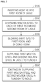
- a casting method for manufacturing a double-layered slab, in which components in a surface layer and an inner layer are different includes: supplying first molten steel accommodated in a first room of a ladle to a first accommodation space of a tundish; supplying second molten steel accommodated in a second room, which is isolated and distinguished from the first room, in the ladle to a second accommodation space of the tundish; and casting a slab by supplying the first and second molten steel of the tundish to a mold.
- the casting method may further include preparing the first molten steel in the first room of the ladle and preparing the second molten steel in the second room, and the preparing of the first molten steel in the first room and the preparing of the second molten steel in the second room may include: inserting an additive into the first room; and charging molten steel having the same component composition to each of the first room and the second room.
- the casting method may further include blowing an inert gas to each of the first room and the second room after the preparing of the first molten steel in the first room and the preparing of the second molten steel in the second room.
- a magnetic flux density may be adjusted to form a concentration gradient in which a concentration of an added component contained in the additive decreases in an inner direction from a surface of the surface layer.
- first molten steel M1 the molten steel accommodated in the first room 130a of the ladle 100 and the first accommodation space 330a of the tundish 300
- second molten steel M2 the molten steel accommodated in the second room 130b of the ladle 100 and the second accommodation space 330b of the tundish 300
- the division member 120 may divide the inner space of the body 110 in the width direction (Y-axial direction) of the tundish 300. To this end, the division member 120 extends in the X-axial direction and a height direction of the body 110, and a lower end of the division member 120 contacts or is coupled to an inner bottom surface of the body 110.
- the division member 120 may have a vertical extension length that is equal to or less than that of the body 110, and thus a height of an upper end of the division member 120 may be equal to or less than that of an upper end of the body 110.
- the division member 120 has a plate shape extending in the vertical direction, the embodiment is not limited thereto.
- the division member 120 may have various shapes capable of dividing the inner space of the body 110 in the width direction (Y-axial direction) of the tundish 300.
- the first plug 140a and the first discharge nozzle 150a are provided at the bottom of the body 110, which corresponds to a lower portion of the first room 130a.
- the first plug 140a and the first discharge nozzle 150a may be arranged in the width direction (Y-axial direction) of the tundish 300.
- the first plug 140a may be relatively adjacent to a sidewall of the body 110, and the first discharge nozzle 150a may be relatively adjacent to the division member 120.
- the second plug 140b and the second discharge nozzle 150b are provided at the bottom of the body 110, which corresponds to a lower portion of the second room 130b.
- the second plug 140b and the second discharge nozzle 150b may be arranged in the width direction (Y-axial direction) of the tundish 300.
- the second plug 140b may be relatively adjacent to the sidewall of the body 110, and the second discharge nozzle 150b may be relatively adjacent to the division member 120.
- the first discharge nozzle 150a may be disposed between the first plug 140a and the division member 120
- the second discharge nozzle 150b may be disposed between the division member 120 and the second plug 140b.
- a gas supply part for supplying an inert gas such as an argon (Ar) gas may be connected to each of the first and second plugs 140a and 140b.
- the inert gas supplied through the gas supply part and the first and second plugs 140a and 140b may be blown to each of the first room 130a and the second room 130b to stir each of the first and second molten steel M1 and M2 or float inclusions.
- the casting installation according to an embodiment of the present invention casts a double-layered slab in which components in a surface layer and an inner layer are different.
- the casting installation casts a double-layered slab in which characteristics of a surface layer and an inner layer are different.
- the first molten steel M1 and the second molten steel M2 which have different components, are provided in the present invention
- the first molten steel M1 and the second molten steel M2 are provided in the ladle 100.
- an additive is inserted to one of the first room 130a and the second room 130b of the ladle 100, e.g., the first room 130a, and then the molten steel having the same component composition is charged to the first room 130a and the second room 130b.
- the first molten steel M1 is prepared, and the molten steel accommodated in the second room 130b becomes the second molten steel M2 having a composition different from that of the first molten steel M1 by the additive.
- a method for preparing the first molten steel M1 and the second molten steel M2 by inserting the additive into the first room 130a and then charging the molten steel having the same composition to each of the first room 130a and the second room 130b is described above.
- the embodiment is not limited thereto.
- various methods may be applied as long as the methods allow the first molten steel M1 to be accommodated in the first room 130a and the second molten steel M2 to be accommodated in the second room 130b.
- the first molten steel M1 and the second molten steel M2, which have different components, may be prepared from the outside of the ladle 100, the first molten steel M1 may be charged to the first room 130a, and the second molten steel M2 may be charged to the second room 130b.
- the additive is a material containing a component that is necessary for the surface layer to have a target function.
- the component that is necessary to have a target function or a preferred function is referred to as an 'added component'.
- the additive may be described as a material containing the added component.
- the added component is not limited to the Cr.
- the added component may be at least one of C, Si, Mn, Ni, and A1 according to a function to be added to the surface layer, e.g., a coatability, a weldability, and an electrical property.
- the molten steel and the additive, which are charged to the first room 130a may be uniformly mixed, and as inclusions generated from each of the first room 130a and the second room 130b may be floated and separated, component adjustment may be further easily performed.
- the inner space of the main body 310 is divided into a space corresponding to an outer side of the partition wall part 320 and a space corresponding to an inner side of the partition wall part 320.
- an outer space of the partition wall part 320 is referred to as a first accommodation space 330a
- an inner space of the partition wall part 320 is referred to as a second accommodation space 330b.
- the tundish 300 includes a main body 310 having an inner space and a partition wall part 320 installed in the main body 310 to divide the inner space of the main body 310 into a first accommodation space 330a and a second accommodation space 330b that is an inner space of the first accommodation space 330a.
- the tundish 300 includes a third phase nozzle 343 passing the bottom surface of the main body 310, which corresponds to the first accommodation space 330a, in the vertical direction to provide the first molten steel M1 to the second mold 410b of the second casting device 400b and a fourth phase nozzle 344 passing the bottom surface of the main body 310, which corresponds to the second accommodation space 330b, in the vertical direction to provide the second molten steel M2 to the second mold 410b of the second casting device 400b.
- the main body 310 has a shape including at least a bottom part and a sidewall part having a predetermined height and surrounding an edge of an upper portion of the bottom part.
- the first to fourth phase nozzles 341, 342, 343, and 344 are provided at the bottom surface of the main body 310, and, as the ladle 100 is disposed above the main body 310, the first and second molten steel is supplied through the first and second discharge nozzles 150a and 150b an d the first and second supply nozzles 200a and 200b.
- a position or a space at which the first and second molten steel M1 and M2 is supplied from the first and second discharge nozzles 150a and 150b to the tundish 300 may be spaced apart from the first to fourth phase nozzles 341, 342, 343, and 344 for discharging the first and second molten steel M1 and M2 to the first and second casting devices 400a and 400b instead of being adjacent thereto.
- the main body 310 may include a first body 311 extending in the X-axial direction (longitudinal direction or first extension direction) and a second body 312 extending in the Y-axial direction (width direction or second extension direction) crossing the extension direction (X-axial direction) of the first body 311.
- an extended length of the second body 312 in the X-axial direction is less than that of the first body 311 in the X-axial direction.
- the first body 311 and the second body 312 may be provided so that a center of the first body 311 in the X-axial direction and a center of the second body 312 in the X-axial direction are positioned on one linear line.
- the main body 310 may have an overall shape extending in the X-axial direction and protruding in the Y-axial direction.
- the inner space of the main body 310 includes a space extending in the X-axial direction and formed by the first body 311 and a protruding space extending in the Y-axial direction from the space extending in the X-axial direction and formed by the second body 312.
- a space of the second body 312 receives the first and second molten steel M1 and M2 from the ladle.
- the first and second molten steel M1 and M2 of the ladle 100 is supplied to the protruding space in the inner space of the main body 310.
- the ladle 100 is disposed above the second body 312 of the tundish 300.
- the partition wall part 320 is installed in the main body 310 to divide the inside of the main body 310 into the first accommodation space 330a and the second accommodation space 330b.
- the partition wall part 320 may have a shape corresponding to the shape of the main body 310.
- the partition wall part 320 may include a first partition wall 321 extending in an arrangement direction (i.e., X-axial direction) of the first to fourth phase nozzles 341, 342, 343, and 3444 or an extension direction of the first body 311 and a second partition wall 322 extending in a direction (Y-axial direction) crossing an extension direction (i.e., X-axial direction) of the first partition wall 321.
- an extended length of the second partition wall 322 in the X-axial direction is less than that of the first partition wall 321 in the X-axial direction.
- the first partition wall 321 and the second partition wall 322 may be provided so that a center of the first partition wall 321 in the X-axial direction and a center of the second partition wall 322 in the X-axial direction are positioned on one linear line.
- the partition wall part 320 may be installed in the main body 310 so that the first partition wall 321 is disposed in the first body 311, and at least a portion of the second body 312 is disposed in the second body 312.
- the other side surface of the first partition wall 321 may contact or be spaced apart from an inner surface of the first body 311, which faces the other side surface. Also, other side surfaces except for the other side surface among outer surfaces of the first partition wall 321 may be spaced apart from the inner surface of the first body 311.
- the entire second partition wall 322 may be installed in the second body 312, or only a portion of the second partition wall 322 may be installed in the second body 312.
- each of the first and second accommodation spaces 330a and 330b may have an overall shape extending in the X-axial direction and protruding in the Y-axial direction by the shapes of the main body 310 and the partition wall part 320.
- each of the first and second accommodation spaces 330a and 330b include a space extending in the X-axial direction and a protruding space extending in the Y-axial direction from the space extending in the X-axial direction.
- the ladle 100 is disposed above the second partition wall 322 and the second body 312 of the tundish 300. More particularly, the first discharge nozzle 150a for supplying the first molten steel M1 to the tundish 300 is installed between the second body 312 and the second partition 322 in correspondence to the first accommodation space 330a. Also, the second discharge nozzle 150b for supplying the second molten steel M2 to the tundish 300 is installed at an inner side of the second partition 322 in correspondence to the second accommodation space 330b.
- the second supply nozzle 200b is disposed between the second discharge nozzle 150b and the tundish 300 and has an upper end connected to the second discharge nozzle 150b.
- the second molten steel M2 discharged from the second discharge nozzle 150b is supplied to the tundish 300 through the second supply nozzle 200b. That is, the second supply nozzle 200b is disposed in correspondence to the second accommodation space 330b of the tundish 300 or the inner space of the second partition wall 322.
- the first to fourth phase nozzles 341, 342, 343, and 344 are arranged in the X-axial direction or the arrangement direction of the molds 410a and 410b of the first and second casting devices 400a and 400b.
- each of the first and third phase nozzles 341 and 343 discharges the first molten steel M1 and communicates with the first accommodation space 330a of the tundish 300. That is, the first phase nozzle 341 is provided at one outer side of the first partition wall 321, and the third phase nozzle 343 is provided at the other outer side of the first partition wall 321. Thus, the first phase nozzle 341 and the third phase nozzle 343 are spaced apart from each other with the first partition wall 321 therebetween in the X-axial direction.
- a spaced distance between the second phase nozzle 342 and the fourth phase nozzle 344 may be greater than each of the spaced distance between the first phase nozzle 341 and the second phase nozzle 342 and the spaced distance between the third phase nozzle 343 and the fourth phase nozzle 344.
- the first casting device 400a includes: a first mold 410a for receiving the first and second molten steel M1 and M2 and initially solidifying the molten steel into a predetermined shape; a first upper submerged entry nozzle 420a for receiving the first molten steel M1 from the ladle 100 to supply the first molten steel M1 to the first mold 410a; a first lower submerged entry nozzle 430a for receiving the second molten steel M2 from the ladle 100 to supply the second molten steel M2 to the first mold 410a and discharging the second molten steel M2 at a position lower than the first upper submerged entry nozzle 420a; and a first magnetic field generation part 460a for applying a direct current (DC) magnetic field into the first mold 410a.
- DC direct current
- the first mold 410a is disposed in correspondence to the first and second phase nozzles 341 and 342 of the tundish 300.
- the first mold 410a receives the molten steel from the tundish 300 and initially solidifies the molten steel into a predetermined shape.
- the first mold 410a may have, e.g., a rectangular cross-sectional shape.
- the first mold 410a includes: one pair of long sides each extending in one direction (X-axial direction) and spaced apart from each other in a direction (Y-axial direction) crossing or perpendicular to the extension direction; and one pair of short sides each extending in a direction (Y-axial direction) crossing or perpendicular to the long side and spaced apart from each other in a direction (X-axial direction) crossing or perpendicular to the extension direction. Also, a flow path through which a coolant for cooling the molten steel flows is prepared in each of the short side and the long side of the first mold 410a.
- the first upper submerged entry nozzle 420a supplies the first molten steel M1 to the first mold 410a
- the first lower submerged entry nozzle 430a supplies the second molten steel M2 to the first mold 410a.
- the first upper submerged entry nozzle 420a and the first lower submerged entry nozzle 430a are arranged and spaced apart from each other in the extension direction (i.e., the X-axial direction) of the long side of the mold.
- first upper submerged entry nozzle 420a and the first lower submerged entry nozzle 430a have different heights of discharge holes through which the molten steel is discharged. That is, a discharge hole (hereinafter, referred to as a first upper discharge hole) of the first upper submerged entry nozzle 420a has a height greater than that of a discharge hole (hereinafter, referred to as a first lower discharge hole) of the first lower submerged entry nozzle 430a. In other words, a first lower discharge hole 431a has a height less than that of a first upper discharge hole 421a.
- the first upper submerged entry nozzle 420a and the first lower submerged entry nozzle 430a may have different lengths, i.e., an extended length of the first upper submerged entry nozzle 420a may be less than that of the first lower submerged entry nozzle 430a, and the discharge hole may be defined at a lower portion of each of the first upper submerged entry nozzle 420a and the first lower submerged entry nozzle 430a.
- upper ends of the first upper submerged entry nozzle 420a and the first lower submerged entry nozzle 430a is connected to the first and second phase nozzles 431 and 432, respectively, disposed above the first mold 410a so that the upper ends have the same height as each other.
- the first upper discharge hole 321a is disposed higher than the first lower discharge hole 431a.
- the first magnetic field generation part 460a is a unit for applying a magnetic force into the first mold 410a, and more particularly, a unit for applying a uniform DC magnetic field in a width direction (Y-axial direction) of the first mold 410a.
- the first magnetic field generation part 460a may be disposed at an outer side of each of the one pair of short sides of the first mold.
- the first cooling bed includes a plurality of first rolls disposed below the first mold 410a and arranged in one direction and a first injection nozzle disposed between the plurality of first rolls to inject coolant toward the slab.
- each of the first roll and the first injection nozzle may be disposed above a top surface and below a bottom surface of the slab, respectively.
- the second casting device 400b has a configuration and a shape, which are similar to those of the first casting device 400a.
- the second casting device 400b includes: a second mold 410b for receiving the first and second molten steel M1 and M2 and initially solidifying the molten steel into a predetermined shape; a second upper submerged entry nozzle 420b for receiving the first molten steel M1 from the ladle 100 to supply the first molten steel M1 to the second mold 410b; a second lower submerged entry nozzle 430b for receiving the second molten steel M2 from the ladle 100 to supply the second molten steel M2 to the second mold 410b and discharging the second molten steel M2 at a position lower than the second lower submerged entry nozzle 420b; and a second magnetic field generation part 460b for generating a magnetic field in the second mold 410b.
- the second mold 410b is spaced apart from the first mold 410a in the X-axial direction and disposed in correspondence to a lower side of the third and fourth nozzles 343 and 344.
- the second upper submerged entry nozzle 420b supplies the first molten steel to the second mold 410b
- the second lower submerged entry nozzle 430b supplies the second molten steel M2 to the second mold 410b.
- the second upper submerged entry nozzle 420b and the second lower submerged entry nozzle 430b are arranged and spaced apart from each other in the extension direction (i.e., the X-axial direction) of the long side of the second mold 410b.
- the second upper submerged entry nozzle 420b and the second lower submerged entry nozzle 430b have different heights of discharge holes through which the molten steel is discharged. That is, a discharge hole (hereinafter, referred to as a second upper discharge hole 421b) of the second upper submerged entry nozzle 420b has a height greater than that of a discharge hole (hereinafter, referred to as a second lower discharge hole 431b) of the second lower submerged entry nozzle 430b.
- the slab drawn from the first mold 410a is solidified while moving in the arrangement direction of the plurality of first rolls
- the slab drawn from the second mold 410b is solidified while moving in the arrangement direction of the plurality of second rolls.
- the first mold 410a and the first cooling bed, through which the molten steel and the mold pass, may be referred to as a first strand
- the second mold 410b and the second cooling bed may be referred to as a second strand. That is, the casting installation according to an embodiment includes a plurality of strands.
- first casting device 400a since the first casting device 400a and the second casting device 400b have the same method for casting the slab, a method for casting the slab in the second casting device 400b will be omitted.
- first molten steel and second molten steel which contain different components, are prepared and supplied to the first mold 410a.
- each of the first molten steel M1 and the second molten steel M2 may be molten steel for low carbon steel containing 0.018 wt% of C, 0.035 wt% of Si, 1.15 wt% of Mn, and 0.1 wt% of Ni.
- the second molten steel M2 may further contain 3 wt% of Cr in comparison with the first molten steel M1.
- a solidification cell (hereinafter, referred to as a first solidification cell C1) is formed.
- a flow path through which coolant flows is buried in an inner wall of the first mold 410a, the inner wall of the first mold 410a has a lowest temperature.
- the first solidification cell C1 is formed along an inner wall surface of the first mold 410a.
- the first solidification cell C1 is formed along the inner wall surface of the first mold 410a, a space surrounded by the first solidification cell C1 is formed, and the second molten steel M2 is supplied to the space through the first lower submerged entry nozzle 430a.
- the second molten steel M2 discharged from the first lower submerged entry nozzle 430a is supplied to fill the space partitioned by the first solidification cell C1.
- the second solidification cell C2 is formed along an inner wall surface of the first solidification cell C1 at a time at which the first molten steel M1 is started to be supplied.
- the first magnetic field generation part 460a is disposed between the first upper discharge hole 421a of the first upper submerged entry nozzle 420a and the first lower discharge hole 431a of the first lower submerged entry nozzle 430a.
- the first molten steel M1 discharged from the first upper discharge hole 421a is discharged to an upper side of the first magnetic field generation part 460a
- the second molten steel M2 discharged from the first lower discharge hole 431a is discharged to a lower side of the first magnetic field generation part 460a.
- most of the first molten steel M1 discharged from the first upper discharge hole 421a of the first upper submerged entry nozzle 420a stays at the upper side of the first magnetic field generation part 460a or moves in an outside direction of the extension direction of the first magnetic field generation part 460a instead of moving to the lower side of the first magnetic field generation part 460a.
- a molten steel pool (i.e., upper pool) formed by the first molten steel M1 and a molten steel pool (i.e., lower pool) formed by the second molten steel M2 may be distinguished.
- the double-layered slab is a slab which is cast by using the first molten steel M1 and the second molten steel M2, which have different components, and in which the components in a surface layer SL and an inner layer IL are different. More particularly, the first molten steel M1 and the second molten steel M2 have different contents of the added components, and thus the contents of the added components in the surface layer SL and the inner layer IL are different.
- the surface layer SL and the inner layer IL of the double-layered slab may be defined or distinguished according to the content (or concentration) of the added component.
- the double-layered slab according to an embodiment has a concentration gradient in which a concentration of the added component gradually decreases in a direction from a surface to an inner side of the surface layer SL (refer to FIG. 5 ).
- the added component may be inevitably contained with a small amount or may not be contained in each of the second molten steel M2 and the inner layer IL.
- a region from the surface of the slab to a point at which the content of the added component contained in the first molten steel M1 is 0.5% may be referred to as the surface layer SL.
- a region in which the content of the added component contained in the first molten steel M1 is in a range from 100% to 0.5% (an inner direction from the surface) may be defined as the surface layer.
- a region in which the content of the added component contained in the first molten steel M1 is less than 0.5% (0% inclusive) may be defined as the inner layer IL.
- the content of the added component in the surface layer SL is varied within a range from 100% to 0.5%. Also, the content of the added component in the inner layer IL may be less than 0.5% or may be 0%.
- the content of the added component gradually decreases in the inner direction from the surface in the surface layer SL.
- a region from a point at which the content of the added component contained in the first molten steel M1 is 90% to a point at which the content is a predetermined ratio is defined as a concentration gradient layer CGA.
- the point at which the content of the added component contained in the first molten steel is 90% is a start point As of the concentration gradient layer, and the point at which the content is the predetermined ratio is an end point Ae of the concentration gradient layer.
- a reference concentration that is the start point As of the concentration gradient layer calculated by the mathematical equation 1 is 2.7 wt%. Also, a point at which the calculated concentration is true is the start point As of the concentration gradient layer.
- a concentration of the added component which is a reference of the end point Ae of the concentration gradient layer, is determined by a sum of 5% of the content of the added component contained in the first molten steel M1 and the content of the added component contained in the second molten steel M2 (refer to mathematical equation 2).
- CGA _ e n d p o int _ reference _ concentration concentration _ of _ addedcomponent _ in _ sec ond _ moltensteel + concentration _ of _ addedcomponent _ in _ first _ moltensteel ⁇ 5 100
- the concentration gradient layer CGA is from a point at which the content of the added component is 2.7 wt% or more to a point at which the content of the added component is 0.16 wt% or less.
- a reference concentration that is the end point of the concentration gradient layer is 0.15 wt%.
- a thickness T of the concentration gradient region CGA is 1.4% to 8.5% of a total thickness of the slab.
- the thickness T of the concentration gradient region CGA represents a length from the start point As of the concentration gradient layer to the end point Ae of the concentration gradient layer.
- the thickness T of the concentration gradient layer CGA increases as the intensity of the magnetic flux density decreases.
- the concentration gradient region CGA may be 1.4% to 8.5% of the total thickness of the slab S.
- the intensity of the magnetic flux density may be 0.2 tesla to 0.8 tesla (equal to or greater than 0.2 tesla and equal to or less than 0.8 tesla).
- a specimen is prepared by sampling a portion of the manufactured slab for a corrosion resistance evaluation. Also, the specimen is evaluated in an atmosphere of sulfuric acid (H 2 S) that is one of strong acid by applying a tensile stress and measuring a yield strength.
- H 2 S sulfuric acid
- the double-layered slab having the concentration gradient on the added component in the surface layer like an embodiment may have a preferred added function, e.g., corrosion resistance.
- the first molten steel M1 and the second molten steel M2 supplied to each of the first and second molds 410a and 410b are semi-solidified in each of the first and second molds 410a and 410b to manufacture the double-layered slab in which the components in the surface layer and the inner layer are different. That is, the double-layered slab in which the first molten steel M1 supplied to the upper side thereof is the surface layer, and the second molten steel M2 supplied to the lower side thereof is the inner layer is manufactured.
- the double-layered slab in which the surface layer SL has the concentration gradient on the added component is manufactured. That is, the surface layer SL has the concentration gradient layer CGA in which the concentration of the added component gradually decreases in a direction from the surface to the inner layer.
- the concentration of the added component is greater in the surface layer SL than the inner layer, and the concentration of the added component gradually increases in a direction toward an outermost surface of the slab S in the surface layer SL.
- the thickness of the concentration gradient layer is 1.4% to 8.5% of the total thickness of the slab.
- the surface layer SL has a function corresponding to the surface layer of the double-layered slab without the concentration gradient, e.g., the corrosion resistance.
- the magnetic force greater than 0.8 tesla is unnecessary to be applied when the double-layered slab is manufactured, the installation is unnecessary to be manufactured with excessively large size for applying 0.8 tesla and thus advantageous to be commercialized.
- the double-layered slab having the uniform component in the longitudinal direction thereof.
- the additive is inserted into and the molten steel is charged to the first room 130a of the ladle 100, and then the inert gas is blown through the first plug 140a, the first molten steel in which the additive and the molten steel is uniformly mixed or the components are uniform may be prepared.
- the double-layered slab in which the components in the surface layer are uniform in the longitudinal direction thereof may be manufactured.
- the installation is configured to include the plurality of strands so that the ladle 100 and the tundish 300 accommodate each of the first molten steel M1 and the second molten steel M2, the production rate of the double-layered slab may improve.
- the production rate of the double-layered slab may improve. Also, as the first molten steel and the second molten steel are separately prepared in the ladle and supplied to the tundish, the double-layered slab in which the components are uniform in the longitudinal direction of the slab may be cast.
Landscapes
- Engineering & Computer Science (AREA)
- Mechanical Engineering (AREA)
- Continuous Casting (AREA)
Abstract
Description
- The present invention relates to a casting installation and a casting method, and more particularly, to a casting installation and a casting method, which are capable of casting a double-layered slab.
- A casting device for manufacturing a double-layered slab in which compositions in a surface layer and a central portion are different includes: a tundish for accommodating first molten steel and second molten steel, which have different compositions; a mold for receiving the molten steel from the tundish and initially solidifying the molten steel into a predetermined shape; first and second nozzles for supplying each of the first and second molten steel in the tundish to the mold; and a magnetic field generation part for generating a direct current magnetic field in the mold.
- In the related art, a beam is prepared in the tundish to separately accommodate the first molten steel and the second molten steel, which have different components, in the tundish, and the inner space is divided into two spaces, i.e., a first space and a second space, based on the beam.
- The beam prepared in the tundish has a length less than a height of the tundish, and a lower end of the beam is spaced apart from a bottom surface of the tundish. Thus, although the inner space is divided through the beam, since the beam is spaced apart from the bottom surface of the tundish, mixture between the first molten steel and the second molten steel may not be completely prevented.
- Particularly, in case of continuous cast of slabs, since an amount of molten steel in the tundish is reduced at a time for replacing the ladle to generate a vortex flow at a lower portion of the tundish, the mixture is inevitably generated. Thus, a slab in which components are not uniform in a longitudinal direction thereof is manufactured by the mixture between the first molten steel and the second molten steel.
- In order to resolve the above-described problem, although bubbling of an argon (Ar) gas toward a bottoms surface of the tundish is performed, since a residence time of the molten steel in the tundish is short, the slab in which components in the longitudinal direction thereof are not uniform is manufactured even by this method.
- Also, since the above-described casting installation has a structure of including one mold and one secondary cooling bed below the tundish, i.e., one strand, a production rate of a double-layered slab is low.
- (Patent document 1) Korean Patent Publication No.
KR 2012-0071475 - The present invention provides a casting installation and a casting method, which are capable of improving a production rate of a double-layered slab.
- The present invention also provides a casting installation and a casting method, which are capable of casting a double-layered slab having a target function.
- According to an embodiment of the present invention, a casting installation includes: a ladle provided with a first room and a second room, each of which accommodates molten steel; a tundish having a first accommodation space configured to accommodate first molten steel supplied from the first room and a second accommodation space configured to accommodate second molten steel supplied from the second room; and a mold that is disposed below the tundish, solidifies the first molten steel and the second molten steel supplied from the tundish, and casts a double-layered slab in which components in a surface layer and an inner layer are different.
- The ladle may include: a body having an inner space; and a division member installed in the body so that the first room and the second room are formed by dividing the inner space of the body, and a bottom surface of the division member may be connected to a bottom surface of the body.
- The ladle may include: a first plug that passes through a bottom of the first room in a vertical direction so that an inert gas is blown to the first room; a second plug that passes through a bottom of the second room in the vertical direction so that an inert gas is blown to the second room; a first discharge nozzle that passes through the bottom of the first room in the vertical direction to discharge the first molten steel; and a second discharge nozzle that passes through the bottom of the second room in the vertical direction to discharge the second molten steel
- The tundish may include: a main body having an inner space; and a partition wall part installed in the main body so that the first accommodation space is an outer space, and the second accommodation space is an inner space in the main body, and a lower end of the partition wall part may be connected to a bottom of the main body.
- The main body may include: a first body extending in a first extension direction; and a second body extending from the first body in a second extension direction crossing the first extension direction, and the partition wall part may include: a first partition wall extending in the extension direction of the first body and accommodated in the first body; and a second partition wall extending in the direction crossing the extension direction of the first body and having at least a portion accommodated in the second body.
- The mold may be disposed below the first partition and the first body of the tundish, and the ladle may be disposed above the second partition and the second body of the tundish.
- The mold may be provided in plurality, and the plurality of molds may be arranged in the first extension direction below the tundish so as to receive the first molten steel and the second molten steel from the tundish.
- The casting installation may further include: a plurality of upper submerged entry nozzles configured to supply the first molten steel of the tundish to the plurality of molds, respectively; and a plurality of lower submerged entry nozzles configured to supply the second molten steel of the tundish to the plurality of molds, respectively.
- The casting device may include a magnetic field generation part configured to apply a magnetic field into the mold.
- A casting method for manufacturing a double-layered slab, in which components in a surface layer and an inner layer are different, includes: supplying first molten steel accommodated in a first room of a ladle to a first accommodation space of a tundish; supplying second molten steel accommodated in a second room, which is isolated and distinguished from the first room, in the ladle to a second accommodation space of the tundish; and casting a slab by supplying the first and second molten steel of the tundish to a mold.
- The casting method may further include preparing the first molten steel in the first room of the ladle and preparing the second molten steel in the second room, and the preparing of the first molten steel in the first room and the preparing of the second molten steel in the second room may include: inserting an additive into the first room; and charging molten steel having the same component composition to each of the first room and the second room.
- The casting method may further include blowing an inert gas to each of the first room and the second room after the preparing of the first molten steel in the first room and the preparing of the second molten steel in the second room.
- The casting method may further include applying a magnetic field into the mold.
- In the applying of the magnetic field into the mold, a magnetic flux density may be adjusted to form a concentration gradient in which a concentration of an added component contained in the additive decreases in an inner direction from a surface of the surface layer.
- The magnetic field may be applied so that the magnetic flux density in the mold is 0.2 tesla to 0.8 tesla.
- The additive may include ferro-alloy containing at least one added component of Cr, C, Si, Mn, Ni, and Al.
- A double-layered slab according to an embodiment of the present invention has a concentration gradient layer having a concentration gradient on an added component in an inner direction from a surface thereof.
- The concentration gradient layer may have a thickness that is 1.4% to 8.5% of a total thickness of a slab.
- As the casting installation according to the embodiment of the present invention is configured to include the plurality of strands, the production rate of the double-layered slab may improve.
- Also, as the first molten steel and the second molten steel are separately prepared in the ladle and supplied to the tundish, the double-layered slab in which the components are uniform in the longitudinal direction of the slab may be manufactured.
- Also, as the additive is inserted into and the molten steel is charged to any one of the plurality of rooms of the ladle, and then the inert gas is blown through the plug, the molten steel in which the additive and the molten steel are uniformly mixed or the components are uniform may be prepared. Thus, the double-layered slab in which the components in the surface layer are uniform in the longitudinal direction thereof may be manufactured.
- Also, as the casting is performed to exhibit the target function only in the surface layer, the double-layered slab may be cast easier than the related art. Thus, since the great magnetic force is unnecessary to be applied to the mold, the magnetic field generation part is unnecessary to be manufactured with excessively large size and thus advantageous to be commercialized.
-
-
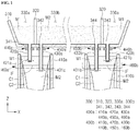
FIG. 1 is a view illustrating a casting installation according to an embodiment of the present invention. -
FIG. 2 is a three-dimensional view for explaining a ladle and a tundish in the casting installation according to an embodiment of the present invention. -
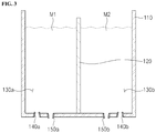
FIG. 3 is a view illustrating the ladle according to an embodiment of the present invention. -
FIG. 4 is a top view illustrating a tundish according to an embodiment of the present invention. -
FIG. 5 is a conceptual view for explaining a density gradient in a double-layered slab cast by a method according to an embodiment of the present invention. -
FIG. 6 is a graph representing a thickness of a density gradient region based on an intensity of a magnetic flux density. -
FIG. 7 is a flowchart sequentially representing a method for casting a double-layered slab according to an embodiment of the present invention. - Hereinafter exemplary embodiments will be described in detail with reference to the accompanying drawings. The present invention may, however, be embodied in different forms and should not be construed as limited to the embodiments set forth herein. Rather, these embodiments are provided so that this disclosure will be thorough and complete, and will fully convey the scope of the present invention to those skilled in the art.
- The present invention relates to a casting installation capable of casting a double-layered slab and a casting method. More particularly, the present invention provides a casting installation and a casting method, which are capable of improving a production rate of a double-layered slab and casting a double-layered slab to have a target function.
-
FIG. 1 is a view illustrating a casting installation according to an embodiment of the present invention.FIG. 2 is a three-dimensional view for explaining a ladle and a tundish in the casting installation according to an embodiment of the present invention.FIG. 3 is a view illustrating the ladle according to an embodiment of the present invention.FIG. 4 is a top view illustrating a tundish according to an embodiment of the present invention.FIG. 5 is a conceptual view for explaining a concentration gradient in a double-layered slab cast by a method according to an embodiment of the present invention. (b) ofFIG. 5 is a conceptual graph representing an added component concentration on one linear line connecting A-A' of (a) ofFIG. 5. FIG. 6 is a graph representing a thickness of a concentration gradient region based on an intensity of a magnetic flux concentration. - Referring to
FIGS. 1 and2 , a casting installation according to an embodiment of the present invention includes: aladle 100 provided with afirst room 130a and asecond room 130b, which of which may accommodate molten steel therein; a tundish having afirst accommodation space 330a and asecond accommodation space 330b, which are separated and provided to accommodate the molten steel provided from thefirst room 130a and thesecond room 130b, respectively; and first and second casting devices 400a and 400b, each of which includes amold first accommodation space 330a and thesecond accommodation space 330b of thetundish 300 and casts a double-layered slab, and which are arranged in a longitudinal direction (X-axial direction) of thetundish 300. - Also, the casting installation according to an embodiment of the present invention includes a
first supply nozzle 200a for supplying the molten steel in thefirst room 130a of theladle 100 to thefirst accommodation space 330a of thetundish 300 and asecond supply nozzle 200b for supplying the molten steel in thesecond room 130b to thesecond accommodation space 330b of thetundish 300. - Hereinafter, for convenience of description, the molten steel accommodated in the
first room 130a of theladle 100 and thefirst accommodation space 330a of thetundish 300 is referred to as first molten steel M1, and the molten steel accommodated in thesecond room 130b of theladle 100 and thesecond accommodation space 330b of thetundish 300 is referred to as second molten steel M2. - Referring to
FIGS. 2 and3 , theladle 100 includes: abody 110 having an inner space capable of accommodating the molten steel; adivision member 120 installed in thebody 110 to divide the inner space of thebody 110 in a width direction (Y-axial direction) crossing the longitudinal direction (X-axial direction) of thetundish 300; afirst plug 140a passing through a bottom of thebody 110, which corresponds to thefirst room 130a, in a vertical direction and capable of blowing a gas; asecond plug 140b passing through a bottom of thebody 110, which corresponds to thesecond room 130b, in the vertical direction and capable of blowing a gas; afirst discharge nozzle 150a passing through the bottom of thebody 110, which corresponds to thefirst room 130a, in the vertical direction and discharging the first molten steel M1 of thefirst room 130a; and asecond discharge nozzle 150b passing through the bottom of thebody 110, which corresponds to thesecond room 130b, in the vertical direction and discharging the second molten steel M2 of thesecond room 130b. - The
division member 120 may divide the inner space of thebody 110 in the width direction (Y-axial direction) of thetundish 300. To this end, thedivision member 120 extends in the X-axial direction and a height direction of thebody 110, and a lower end of thedivision member 120 contacts or is coupled to an inner bottom surface of thebody 110. Thedivision member 120 may have a vertical extension length that is equal to or less than that of thebody 110, and thus a height of an upper end of thedivision member 120 may be equal to or less than that of an upper end of thebody 110. - The
division member 120 divides the inner space of thebody 110 into thefirst room 130a and thesecond room 130b based on thedivision member 120. In other words, thefirst room 130a and thesecond room 130b may be isolated and divided by thedivision member 120. - Although the
division member 120 according to an embodiment has a plate shape extending in the vertical direction, the embodiment is not limited thereto. For example, thedivision member 120 may have various shapes capable of dividing the inner space of thebody 110 in the width direction (Y-axial direction) of thetundish 300. - The
first plug 140a and thefirst discharge nozzle 150a are provided at the bottom of thebody 110, which corresponds to a lower portion of thefirst room 130a. Here, thefirst plug 140a and thefirst discharge nozzle 150a may be arranged in the width direction (Y-axial direction) of thetundish 300. Thefirst plug 140a may be relatively adjacent to a sidewall of thebody 110, and thefirst discharge nozzle 150a may be relatively adjacent to thedivision member 120. - The
second plug 140b and thesecond discharge nozzle 150b are provided at the bottom of thebody 110, which corresponds to a lower portion of thesecond room 130b. Here, thesecond plug 140b and thesecond discharge nozzle 150b may be arranged in the width direction (Y-axial direction) of thetundish 300. Thesecond plug 140b may be relatively adjacent to the sidewall of thebody 110, and thesecond discharge nozzle 150b may be relatively adjacent to thedivision member 120. - A lower end of each of the
first discharge nozzle 150a and thesecond discharge nozzle 150b may protrude downward from a bottom surface of theladle 100. - According to arrangement of the first and
second plugs second discharge nozzles first discharge nozzle 150a may be disposed between thefirst plug 140a and thedivision member 120, and thesecond discharge nozzle 150b may be disposed between thedivision member 120 and thesecond plug 140b. - Also, a gas supply part for supplying an inert gas such as an argon (Ar) gas may be connected to each of the first and
second plugs second plugs first room 130a and thesecond room 130b to stir each of the first and second molten steel M1 and M2 or float inclusions. - As described above, the casting installation according to an embodiment of the present invention casts a double-layered slab in which components in a surface layer and an inner layer are different. In other words, the casting installation casts a double-layered slab in which characteristics of a surface layer and an inner layer are different.
- When the first molten steel M1 and the second molten steel M2, which have different components, are provided in the present invention, the first molten steel M1 and the second molten steel M2 are provided in the
ladle 100. In more detail, an additive is inserted to one of thefirst room 130a and thesecond room 130b of theladle 100, e.g., thefirst room 130a, and then the molten steel having the same component composition is charged to thefirst room 130a and thesecond room 130b. Thus, as the molten steel charged to thefirst room 130a is mixed with the additive, the first molten steel M1 is prepared, and the molten steel accommodated in thesecond room 130b becomes the second molten steel M2 having a composition different from that of the first molten steel M1 by the additive. - A method for preparing the first molten steel M1 and the second molten steel M2 by inserting the additive into the
first room 130a and then charging the molten steel having the same composition to each of thefirst room 130a and thesecond room 130b is described above. However, the embodiment is not limited thereto. For example, various methods may be applied as long as the methods allow the first molten steel M1 to be accommodated in thefirst room 130a and the second molten steel M2 to be accommodated in thesecond room 130b. For example, the first molten steel M1 and the second molten steel M2, which have different components, may be prepared from the outside of theladle 100, the first molten steel M1 may be charged to thefirst room 130a, and the second molten steel M2 may be charged to thesecond room 130b. - Here, the additive is a material containing a component that is necessary for the surface layer to have a target function. Hereinafter, the component that is necessary to have a target function or a preferred function is referred to as an 'added component'. Thus, the additive may be described as a material containing the added component.
- Also, the component that is necessary to have a target function of the surface layer, i.e., the added component, may be Cr, and the additive may be a material containing Cr, e.g., ferro-alloy.
- However, the added component is not limited to the Cr. The added component may be at least one of C, Si, Mn, Ni, and A1 according to a function to be added to the surface layer, e.g., a coatability, a weldability, and an electrical property.
- Also, as the molten steel is charged to each of the
first room 130a and thesecond room 130b, to which the additive is inserted, and then an inert gas is blown by using the first andsecond plugs first room 130a, may be uniformly mixed, and as inclusions generated from each of thefirst room 130a and thesecond room 130b may be floated and separated, component adjustment may be further easily performed. - As illustrated in
FIGS. 2 and4 , thetundish 300 includes amain body 310 having an inner space and apartition wall part 320 having an inner space and installed in themain body 310 to divide the inner space of themain body 310 into an inner space and an outer space. - As the
partition wall part 320 having the inner space is installed in themain body 310, the inner space of themain body 310 is divided into a space corresponding to an outer side of thepartition wall part 320 and a space corresponding to an inner side of thepartition wall part 320. Hereinafter, in the inner space of themain body 310, an outer space of thepartition wall part 320 is referred to as afirst accommodation space 330a, and an inner space of thepartition wall part 320 is referred to as asecond accommodation space 330b. - Hereinafter, a configuration of the
tundish 300 will be described in detail. - The
tundish 300 includes amain body 310 having an inner space and apartition wall part 320 installed in themain body 310 to divide the inner space of themain body 310 into afirst accommodation space 330a and asecond accommodation space 330b that is an inner space of thefirst accommodation space 330a. - Also, the
tundish 300 includes afirst phase nozzle 341 passing a bottom surface of themain body 310, which corresponds to thefirst accommodation space 330a, in the vertical direction to provide the first molten steel M1 to themold 410a of the first casting device 400a and asecond phase nozzle 342 passing a bottom surface of themain body 310, which corresponds to thesecond accommodation space 330b, in the vertical direction to provide the second molten steel M2 to thefirst mold 410a of the first casting device 400a. - Also, the
tundish 300 includes athird phase nozzle 343 passing the bottom surface of themain body 310, which corresponds to thefirst accommodation space 330a, in the vertical direction to provide the first molten steel M1 to thesecond mold 410b of the second casting device 400b and afourth phase nozzle 344 passing the bottom surface of themain body 310, which corresponds to thesecond accommodation space 330b, in the vertical direction to provide the second molten steel M2 to thesecond mold 410b of the second casting device 400b. - The
main body 310 has a shape including at least a bottom part and a sidewall part having a predetermined height and surrounding an edge of an upper portion of the bottom part. - Also, as described above, the first to
fourth phase nozzles main body 310, and, as theladle 100 is disposed above themain body 310, the first and second molten steel is supplied through the first andsecond discharge nozzles second supply nozzles - Here, a position or a space at which the first and second molten steel M1 and M2 is supplied from the first and
second discharge nozzles tundish 300 may be spaced apart from the first tofourth phase nozzles - To this end, the
main body 310 according to an embodiment may include afirst body 311 extending in the X-axial direction (longitudinal direction or first extension direction) and asecond body 312 extending in the Y-axial direction (width direction or second extension direction) crossing the extension direction (X-axial direction) of thefirst body 311. - Here, an extended length of the
second body 312 in the X-axial direction is less than that of thefirst body 311 in the X-axial direction. Also, thefirst body 311 and thesecond body 312 may be provided so that a center of thefirst body 311 in the X-axial direction and a center of thesecond body 312 in the X-axial direction are positioned on one linear line. - Thus, the
main body 310 may have an overall shape extending in the X-axial direction and protruding in the Y-axial direction. Thus, the inner space of themain body 310 includes a space extending in the X-axial direction and formed by thefirst body 311 and a protruding space extending in the Y-axial direction from the space extending in the X-axial direction and formed by thesecond body 312. - In the
tundish 300, a space of thesecond body 312 receives the first and second molten steel M1 and M2 from the ladle. In other words, the first and second molten steel M1 and M2 of theladle 100 is supplied to the protruding space in the inner space of themain body 310. To this end, theladle 100 is disposed above thesecond body 312 of thetundish 300. - The
partition wall part 320 is installed in themain body 310 to divide the inside of themain body 310 into thefirst accommodation space 330a and thesecond accommodation space 330b. Thepartition wall part 320 may have a shape corresponding to the shape of themain body 310. - That is, the
partition wall part 320 may include afirst partition wall 321 extending in an arrangement direction (i.e., X-axial direction) of the first tofourth phase nozzles first body 311 and asecond partition wall 322 extending in a direction (Y-axial direction) crossing an extension direction (i.e., X-axial direction) of thefirst partition wall 321. - Here, an extended length of the
second partition wall 322 in the X-axial direction is less than that of thefirst partition wall 321 in the X-axial direction. Also, thefirst partition wall 321 and thesecond partition wall 322 may be provided so that a center of thefirst partition wall 321 in the X-axial direction and a center of thesecond partition wall 322 in the X-axial direction are positioned on one linear line. - The
partition wall part 320 may be installed in themain body 310 so that thefirst partition wall 321 is disposed in thefirst body 311, and at least a portion of thesecond body 312 is disposed in thesecond body 312. - Here, on the basis of the Y-axial direction, the other side surface of the
first partition wall 321 may contact or be spaced apart from an inner surface of thefirst body 311, which faces the other side surface. Also, other side surfaces except for the other side surface among outer surfaces of thefirst partition wall 321 may be spaced apart from the inner surface of thefirst body 311. - Also, the entire
second partition wall 322 may be installed in thesecond body 312, or only a portion of thesecond partition wall 322 may be installed in thesecond body 312. - As described above, the inner space of the
tundish 300 is divided into thefirst accommodation space 330a and thesecond accommodation space 330b by themain body 310 and thepartition wall part 320. That is, the inner space of thetundish 300 is divided into thefirst accommodation space 330a corresponding to an outer side of thepartition wall part 320 and thesecond accommodation space 330b corresponding to an inner side of thepartition wall part 320. - Also, each of the first and
second accommodation spaces main body 310 and thepartition wall part 320. In other words, each of the first andsecond accommodation spaces - In the
tundish 300, a space of thesecond partition wall 322 receives the first and second molten steel M1 and M2 from theladle 100. In other words, the first and second molten steel M1 and M2 of the ladle is supplied to the protruding space in the inner space of thepartition wall part 320. - To this end, the
ladle 100 is disposed above thesecond partition wall 322 and thesecond body 312 of thetundish 300. More particularly, thefirst discharge nozzle 150a for supplying the first molten steel M1 to thetundish 300 is installed between thesecond body 312 and thesecond partition 322 in correspondence to thefirst accommodation space 330a. Also, thesecond discharge nozzle 150b for supplying the second molten steel M2 to thetundish 300 is installed at an inner side of thesecond partition 322 in correspondence to thesecond accommodation space 330b. - The
first supply nozzle 200a is disposed between thefirst discharge nozzle 150a and thetundish 300 and has an upper end connected to thefirst discharge nozzle 150a. Thus, the first molten steel M1 discharged from thefirst discharge nozzle 150a is supplied to thetundish 300 through thefirst supply nozzle 200a. That is, thefirst supply nozzle 200a is disposed in correspondence to thefirst accommodation space 330a of thetundish 300 or the outer space of thesecond partition wall 322. - The
second supply nozzle 200b is disposed between thesecond discharge nozzle 150b and thetundish 300 and has an upper end connected to thesecond discharge nozzle 150b. Thus, the second molten steel M2 discharged from thesecond discharge nozzle 150b is supplied to thetundish 300 through thesecond supply nozzle 200b. That is, thesecond supply nozzle 200b is disposed in correspondence to thesecond accommodation space 330b of thetundish 300 or the inner space of thesecond partition wall 322. - Each of the first to
fourth phase nozzles molds - As described above, the first to
fourth phase nozzles molds - More particularly, each of the first and
third phase nozzles first accommodation space 330a of thetundish 300. That is, thefirst phase nozzle 341 is provided at one outer side of thefirst partition wall 321, and thethird phase nozzle 343 is provided at the other outer side of thefirst partition wall 321. Thus, thefirst phase nozzle 341 and thethird phase nozzle 343 are spaced apart from each other with thefirst partition wall 321 therebetween in the X-axial direction. - Each of the second and
fourth phase nozzles second accommodation space 330b of thetundish 300. That is, the second andfourth phase nozzles first partition wall 321, and thesecond phase nozzle 342 and thefourth phase nozzle 344 are arranged and spaced apart from each other in the X-axial direction. - Here, when the
second phase nozzle 342 and the fourth phase nozzle are provided in thefirst partition 321, a spaced distance between thefirst phase nozzle 341 and thesecond phase nozzle 342 is less than one directional length of themold 410a of the first casting device 400a, which will be described later, and a spaced distance between thethird phase nozzle 343 and thefourth phase nozzle 344 is less than one directional length of themold 410b of the second casting device 400b. - Also, a spaced distance between the
second phase nozzle 342 and thefourth phase nozzle 344 may be greater than each of the spaced distance between thefirst phase nozzle 341 and thesecond phase nozzle 342 and the spaced distance between thethird phase nozzle 343 and thefourth phase nozzle 344. - The first and second casting devices 400a and 400b cast a double-layered slab by receiving the first molten steel M1 and the second molten steel M2 from the
tundish 300. The first casting device 400a and the second casting device 400b are overall arranged in the arrangement direction of the first tofourth phase nozzles - Hereinafter, the first and second casting devices 400a and 400b will be described.
- The first casting device 400a includes: a
first mold 410a for receiving the first and second molten steel M1 and M2 and initially solidifying the molten steel into a predetermined shape; a first upper submergedentry nozzle 420a for receiving the first molten steel M1 from theladle 100 to supply the first molten steel M1 to thefirst mold 410a; a first lower submergedentry nozzle 430a for receiving the second molten steel M2 from theladle 100 to supply the second molten steel M2 to thefirst mold 410a and discharging the second molten steel M2 at a position lower than the first upper submergedentry nozzle 420a; and a first magnetic field generation part 460a for applying a direct current (DC) magnetic field into thefirst mold 410a. - Also, the first casting device 400a includes: a
first gate 440a for coupling thefirst phase nozzle 341 and the first upper submergedentry nozzle 420a to each other and controlling communication between thefirst phase nozzle 341 and the first upper submergedentry nozzle 420a; asecond gate 450a for coupling thesecond phase nozzle 342 and the first lower submergedentry nozzle 430a to each other and controlling communication between thesecond phase nozzle 342 and the first lower submergedentry nozzle 430a; and a first cooling bed (not shown) which is provided below thefirst mold 410a and in which a plurality of first rolls and a plurality of first injection nozzles are consecutively arranged so as to perform a series of mold operations while secondarily cooling a slab in a semi-solidified state, which is drawn from thefirst mold 410a. - The
first mold 410a is disposed in correspondence to the first andsecond phase nozzles tundish 300. Thefirst mold 410a receives the molten steel from thetundish 300 and initially solidifies the molten steel into a predetermined shape. Thefirst mold 410a may have, e.g., a rectangular cross-sectional shape. That is, thefirst mold 410a includes: one pair of long sides each extending in one direction (X-axial direction) and spaced apart from each other in a direction (Y-axial direction) crossing or perpendicular to the extension direction; and one pair of short sides each extending in a direction (Y-axial direction) crossing or perpendicular to the long side and spaced apart from each other in a direction (X-axial direction) crossing or perpendicular to the extension direction. Also, a flow path through which a coolant for cooling the molten steel flows is prepared in each of the short side and the long side of thefirst mold 410a. - The first upper submerged
entry nozzle 420a supplies the first molten steel M1 to thefirst mold 410a, and the first lower submergedentry nozzle 430a supplies the second molten steel M2 to thefirst mold 410a. The first upper submergedentry nozzle 420a and the first lower submergedentry nozzle 430a are arranged and spaced apart from each other in the extension direction (i.e., the X-axial direction) of the long side of the mold. - Also, the first upper submerged
entry nozzle 420a and the first lower submergedentry nozzle 430a have different heights of discharge holes through which the molten steel is discharged. That is, a discharge hole (hereinafter, referred to as a first upper discharge hole) of the first upper submergedentry nozzle 420a has a height greater than that of a discharge hole (hereinafter, referred to as a first lower discharge hole) of the first lower submergedentry nozzle 430a. In other words, a firstlower discharge hole 431a has a height less than that of a firstupper discharge hole 421a. - To this end, the first upper submerged
entry nozzle 420a and the first lower submergedentry nozzle 430a may have different lengths, i.e., an extended length of the first upper submergedentry nozzle 420a may be less than that of the first lower submergedentry nozzle 430a, and the discharge hole may be defined at a lower portion of each of the first upper submergedentry nozzle 420a and the first lower submergedentry nozzle 430a. Also, upper ends of the first upper submergedentry nozzle 420a and the first lower submergedentry nozzle 430a is connected to the first and second phase nozzles 431 and 432, respectively, disposed above thefirst mold 410a so that the upper ends have the same height as each other. Thus, the first upper discharge hole 321a is disposed higher than the firstlower discharge hole 431a. - The first magnetic field generation part 460a is a unit for applying a magnetic force into the
first mold 410a, and more particularly, a unit for applying a uniform DC magnetic field in a width direction (Y-axial direction) of thefirst mold 410a. The first magnetic field generation part 460a may be disposed at an outer side of each of the one pair of short sides of the first mold. - Although the first cooling bed is not shown, the first cooling bed includes a plurality of first rolls disposed below the
first mold 410a and arranged in one direction and a first injection nozzle disposed between the plurality of first rolls to inject coolant toward the slab. Here, each of the first roll and the first injection nozzle may be disposed above a top surface and below a bottom surface of the slab, respectively. Thus, the slab drawn from the first mold is completely solidified such that the slab is secondarily cooled by the coolant injected from the first injection nozzle while moving in an arrangement direction of the first rolls. - The second casting device 400b has a configuration and a shape, which are similar to those of the first casting device 400a.
- That is, the second casting device 400b includes: a
second mold 410b for receiving the first and second molten steel M1 and M2 and initially solidifying the molten steel into a predetermined shape; a second upper submergedentry nozzle 420b for receiving the first molten steel M1 from theladle 100 to supply the first molten steel M1 to thesecond mold 410b; a second lower submergedentry nozzle 430b for receiving the second molten steel M2 from theladle 100 to supply the second molten steel M2 to thesecond mold 410b and discharging the second molten steel M2 at a position lower than the second lower submergedentry nozzle 420b; and a second magneticfield generation part 460b for generating a magnetic field in thesecond mold 410b. - Also, the second casting device 400b includes: a
third gate 440b for coupling thethird phase nozzle 343 and the second upper submergedentry nozzle 420b to each other and controlling communication between thethird phase nozzle 343 and the second upper submergedentry nozzle 420b; afourth gate 450b for coupling thefourth phase nozzle 344 and the second lower submergedentry nozzle 430b to each other and controlling communication between thefourth phase nozzle 344 and the second lower submergedentry nozzle 430a; and a second cooling bed (not shown) which is provided below thesecond mold 410b and in which a plurality of second rolls and a plurality of second injection nozzles are consecutively arranged so as to perform a series of mold operations while cooling a semi-solidified slab drawn from thesecond mold 410b. - The
second mold 410b is spaced apart from thefirst mold 410a in the X-axial direction and disposed in correspondence to a lower side of the third andfourth nozzles - The second upper submerged
entry nozzle 420b supplies the first molten steel to thesecond mold 410b, and the second lower submergedentry nozzle 430b supplies the second molten steel M2 to thesecond mold 410b. The second upper submergedentry nozzle 420b and the second lower submergedentry nozzle 430b are arranged and spaced apart from each other in the extension direction (i.e., the X-axial direction) of the long side of thesecond mold 410b. - Also, the second upper submerged
entry nozzle 420b and the second lower submergedentry nozzle 430b have different heights of discharge holes through which the molten steel is discharged. That is, a discharge hole (hereinafter, referred to as a secondupper discharge hole 421b) of the second upper submergedentry nozzle 420b has a height greater than that of a discharge hole (hereinafter, referred to as a secondlower discharge hole 431b) of the second lower submergedentry nozzle 430b. - Although the second cooling bed is not shown, the second cooling bed includes a plurality of second rolls disposed below the second mold and arranged in one direction and a second injection nozzle disposed between the plurality of second rolls to inject coolant toward the slab.
- As described above, the slab drawn from the
first mold 410a is solidified while moving in the arrangement direction of the plurality of first rolls, and the slab drawn from thesecond mold 410b is solidified while moving in the arrangement direction of the plurality of second rolls. - Here, the
first mold 410a and the first cooling bed, through which the molten steel and the mold pass, may be referred to as a first strand, and thesecond mold 410b and the second cooling bed may be referred to as a second strand. That is, the casting installation according to an embodiment includes a plurality of strands. - Hereinafter, a method for casting a double-layered slab by the first casting device 400a will be described. Here, since the first casting device 400a and the second casting device 400b have the same method for casting the slab, a method for casting the slab in the second casting device 400b will be omitted.
- First, first molten steel and second molten steel, which contain different components, are prepared and supplied to the
first mold 410a. Here, each of the first molten steel M1 and the second molten steel M2 may be molten steel for low carbon steel containing 0.018 wt% of C, 0.035 wt% of Si, 1.15 wt% of Mn, and 0.1 wt% of Ni. Also, the second molten steel M2 may further contain 3 wt% of Cr in comparison with the first molten steel M1. - When the first molten steel M1 is supplied to the first mold 10 through the first upper submerged
entry nozzle 420a, as the first molten steel M1 is solidified, a solidification cell (hereinafter, referred to as a first solidification cell C1) is formed. Here, since a flow path through which coolant flows is buried in an inner wall of thefirst mold 410a, the inner wall of thefirst mold 410a has a lowest temperature. Thus, when the first molten steel M1 is supplied, the first solidification cell C1 is formed along an inner wall surface of thefirst mold 410a. Also, since the first solidification cell C1 is formed along the inner wall surface of thefirst mold 410a, a space surrounded by the first solidification cell C1 is formed, and the second molten steel M2 is supplied to the space through the first lower submergedentry nozzle 430a. In other words, the second molten steel M2 discharged from the first lower submergedentry nozzle 430a is supplied to fill the space partitioned by the first solidification cell C1. Also, when the second molten steel M2 supplied from the first lower submergedentry nozzle 430a is solidified to form a solidification cell (hereinafter, referred to as a second solidification cell C2), the second solidification cell C2 is formed along an inner wall surface of the first solidification cell C1 at a time at which the first molten steel M1 is started to be supplied. - Also, the first magnetic field generation part 460a is disposed between the first
upper discharge hole 421a of the first upper submergedentry nozzle 420a and the firstlower discharge hole 431a of the first lower submergedentry nozzle 430a. Thus, the first molten steel M1 discharged from the firstupper discharge hole 421a is discharged to an upper side of the first magnetic field generation part 460a, and the second molten steel M2 discharged from the firstlower discharge hole 431a is discharged to a lower side of the first magnetic field generation part 460a. - Here, a magnetic field applied from the first magnetic field generation part 460a serves as a resistor for suppressing the first molten steel M1 from moving the lower side of the first magnetic field generation part 460a and the second molten steel M2 from moving the upper side of the first magnetic field generation part 460a.
- Here, most of the first molten steel M1 discharged from the first
upper discharge hole 421a of the first upper submergedentry nozzle 420a stays at the upper side of the first magnetic field generation part 460a or moves in an outside direction of the extension direction of the first magnetic field generation part 460a instead of moving to the lower side of the first magnetic field generation part 460a. - Thus, on the basis of a position around the first magnetic field generation part 460a or a position corresponding to the first magnetic field generation part 460a in the
first mold 410a, a molten steel pool (i.e., upper pool) formed by the first molten steel M1 and a molten steel pool (i.e., lower pool) formed by the second molten steel M2 may be distinguished. - As described above, the double-layered slab is a slab which is cast by using the first molten steel M1 and the second molten steel M2, which have different components, and in which the components in a surface layer SL and an inner layer IL are different. More particularly, the first molten steel M1 and the second molten steel M2 have different contents of the added components, and thus the contents of the added components in the surface layer SL and the inner layer IL are different. Thus, the surface layer SL and the inner layer IL of the double-layered slab may be defined or distinguished according to the content (or concentration) of the added component.
- Also, the double-layered slab according to an embodiment has a concentration gradient in which a concentration of the added component gradually decreases in a direction from a surface to an inner side of the surface layer SL (refer to
FIG. 5 ). Also, the added component may be inevitably contained with a small amount or may not be contained in each of the second molten steel M2 and the inner layer IL. - As described above, in the double-layered slab according to an embodiment, a region from the surface of the slab to a point at which the content of the added component contained in the first molten steel M1 is 0.5% may be referred to as the surface layer SL. In other words, a region in which the content of the added component contained in the first molten steel M1 is in a range from 100% to 0.5% (an inner direction from the surface) may be defined as the surface layer.
- Also, a region in which the content of the added component contained in the first molten steel M1 is less than 0.5% (0% inclusive) may be defined as the inner layer IL.
- According to the above definition, the content of the added component in the surface layer SL is varied within a range from 100% to 0.5%. Also, , the content of the added component in the inner layer IL may be less than 0.5% or may be 0%.
- As described above, the content of the added component gradually decreases in the inner direction from the surface in the surface layer SL. Here, in the surface layer SL, a region from a point at which the content of the added component contained in the first molten steel M1 is 90% to a point at which the content is a predetermined ratio is defined as a concentration gradient layer CGA.
- Here, the point at which the content of the added component contained in the first molten steel is 90% is a start point As of the concentration gradient layer, and the point at which the content is the predetermined ratio is an end point Ae of the concentration gradient layer.
- Since a concentration of the added component, which is a reference of the start point As of the concentration gradient layer, is that the content of the added component contained in the first molten steel M1 is 90%, this may be expressed by mathematical equation 1 below.

- For example, when a content of Cr that is the added component in the first molten steel M1 is 3 wt%, a reference concentration that is the start point As of the concentration gradient layer calculated by the mathematical equation 1 is 2.7 wt%. Also, a point at which the calculated concentration is true is the start point As of the concentration gradient layer.
- Also, a concentration of the added component, which is a reference of the end point Ae of the concentration gradient layer, is determined by a sum of 5% of the content of the added component contained in the first molten steel M1 and the content of the added component contained in the second molten steel M2 (refer to mathematical equation 2).

- For example, when a condition, in which a content of Cr that is the added component in the first molten steel M1 is 3 wt% and a content of Cr in the second molten steel M2 is 0.01 wt%, is applied to the mathematical equation 1, a reference concentration that is the end point Ae of the concentration gradient layer is 0.16 wt%. Also, a point that is the reference concentration of the calculated end point may be the end point Ae.
- Thus, the concentration gradient layer CGA is from a point at which the content of the added component is 2.7 wt% or more to a point at which the content of the added component is 0.16 wt% or less.
- For another example, when the added component is not contained in the second molten steel M2 (0%), a reference concentration that is the end point of the concentration gradient layer is 0.15 wt%.
- In an embodiment, a thickness T of the concentration gradient region CGA is 1.4% to 8.5% of a total thickness of the slab. Here, the thickness T of the concentration gradient region CGA represents a length from the start point As of the concentration gradient layer to the end point Ae of the concentration gradient layer.
- In order to cast the double-layered slab in which the components in the surface layer and the inner layer are different, a magnetic field is applied to the
mold field generation part 460a and 460b. Also, an intensity of a magnetic flux density applied from the first and second magneticfield generation parts 460a and 460b is adjusted to 0.2 tesla to 0.8 tesla so that the surface layer has a concentration gradient or has the concentration gradient layer CGA while the thickness T of the concentration gradient layer CGA is 1.4% to 8.5% of the total thickness of the slab. - Referring to
FIG. 6 , the thickness T of the concentration gradient layer CGA increases as the intensity of the magnetic flux density decreases. The concentration gradient region CGA may be 1.4% to 8.5% of the total thickness of the slab S. To this end, as illustrated inFIG. 6 , the intensity of the magnetic flux density may be 0.2 tesla to 0.8 tesla (equal to or greater than 0.2 tesla and equal to or less than 0.8 tesla). - When the intensity of the magnetic flux density is less than 0.2 tesla, a large amount of the first molten steel and the second molten steel are mixed so that a boundary area does not exist in the mold. Thus, the slab in which the contents of the components in the surface layer and the inner layer are equal may be cast. That is, the double-layered slab may not be manufactured.
- On the contrary, when the intensity of the magnetic flux density greater than 0.8 tesla, the casting installation may excessively increase in size and thus may not be commercialized.
- Also, as the thickness of the concentration gradient region CGA decreases, a boundary with respect to the concentrations of the added components between the surface layer and the inner layer becomes clear.
- However, although the thickness of the concentration gradient region CGA is not less than 1.4% of the total thickness of the slab or not clear, and the concentration gradient region CGA is equal to or greater than 1.4%, the surface layer of the slab S may have a function to be added (e.g., corrosion resistance) by the added component. Thus, the thickness of the concentration gradient region CGA is not necessary to be less than 1.4%.
- Thus, in an embodiment, the intensity of the magnetic flux density is adjusted to 0.2 tesla to 0.8 tesla (equal to or greater than 0.2 tesla and equal to or less than 0.8 tesla) so that the thickness of the concentration gradient region CGA is 1.4% to 8.5% of the total thickness of the slab.
- Whether the surface layer has a target property when the double-layered slab is cast by a method according to an embodiment is evaluated. Here, the double-layered slab is cast by the same method as the embodiment using Cr as the added component and the first molten steel and the second molten steel, which have different Cr contents, and as the intensity of the magnetic flux density is adjusted to 0.2 tesla to 0.8 tesla to cast the double-layered slab having the concentration gradient region.
- Also, a specimen is prepared by sampling a portion of the manufactured slab for a corrosion resistance evaluation. Also, the specimen is evaluated in an atmosphere of sulfuric acid (H2S) that is one of strong acid by applying a tensile stress and measuring a yield strength.
- It is checked that the specimen manufactured by the method according to an embodiment and having a concentration gradient in a thickness direction therein guarantees 110% or more of specified minimum yield strength (SMYA). The double-layered slab according to an embodiment guarantees 110% of yield strength at a room temperature.
- Also, a specimen obtained by sampling a general slab in which a surface layer and an inner layer have the same component guarantees about 90% of specified minimum yield strength (SMYA).
- From this, it is known that even the double-layered slab having the concentration gradient on the added component in the surface layer like an embodiment may have a preferred added function, e.g., corrosion resistance.
- As described above, the double-layered slab according to an embodiment of the present invention may be cast to have a preferred function to be added to the surface layer, e.g., sufficient corrosion resistance, and have a concentration gradient instead of having a distinct boundary on the added component concentration between the surface layer and the inner layer like the related art.
- In other words, the surface of the slab S has the function to be added thereto, e.g., corrosion resistance, and difference between contents of the components in the surface layer and the inner layer based on the boundary between the surface layer and the inner layer is less than the related art. Thus, separation between the surface layer and the inner layer caused by component difference and generation of a crack or a defect may be reduced.
- Hereinafter, a method for casting a double-layered slab according to an embodiment of the present invention will be described with reference to
FIGS. 1 to 5 and7 . -
FIG. 7 is a flowchart sequentially representing the method for casting a double-layered slab according to an embodiment of the present invention. - First, an additive is inserted to one of the
first room 130a and thesecond room 130b, e.g., thefirst room 130a, in theladle 100 in a process S100. - Here, the additive, which is for preparing the first molten steel M1 and the second molten steel M2, which have different component compositions, may be ferro-alloy containing a component to be differentiated. Here, the added component may be Cr, and the additive may be a material containing Cr, e.g., ferro-alloy.
- When the additive containing Cr is inserted to the
first room 130a of theladle 100, molten steel is charged to each of thefirst room 130a and thesecond room 130b in a process S200. Here, the molten steel charged to thefirst room 130a and thesecond room 130b may have the same component composition. For example, the molten steel charged to thefirst room 130a and thesecond room 130b may be molten steel for low carbon steel containing 0.018 wt% of C, 0.035 wt% of Si, 1.15 wt% of Mn, and 0.1 wt% of Ni. - Also, when the molten steel is charged to the
first room 130a, the ferro-alloy is melted by a temperature of the molten steel. Thus, the molten steel accommodated in thefirst room 130a is manufactured as molten steel having a different Cr content from the molten steel accommodated in thesecond room 130b or molten steel containing more amount of Cr. - That is, when the additive containing Cr is inserted into the
first room 130a, and then the molten steel is charged to each of thefirst room 130a and thesecond room 130b, the molten steel accommodated in thefirst room 130a and the molten steel accommodated in thesecond room 130b have different compositions. That is, the first molten steel M1 accommodated in thefirst room 130a and the second molten steel M2 accommodated in thesecond room 130b are different in Cr content. Here, the Cr content in the first molten steel M1 may be adjusted to, e.g., 3 wt%, by controlling the insertion amount of the additive and the kind of additive. - Here, the first molten steel M1 containing Cr is prepared to cast the double-layered slab having improved corrosion resistance of the surface layer.
- When the first molten steel M1 and the second molten steel M2 are prepared in the
ladle 100, an inert gas, e.g., an argon (Ar) gas, is blown through each of the first andsecond plugs first room 130a may be mixed by the Ar gas blown through the first andsecond plugs 140b, and separation-floatation of inclusions may be generated in each of thefirst room 130a and thesecond room 130b. - Thereafter, the
ladle 100 moves above thetundish 300, and the first molten steel M1 and the second molten steel M2 are supplied to thetundish 300 in a process S400. To this end, theladle 100 is disposed in correspondence to an upper side of thesecond partition 322 and thesecond body 312 of thetundish 300, and the first andsecond supply nozzles ladle 100 and thetundish 300. Here, thefirst discharge nozzle 150a and thefirst supply nozzle 200a is disposed in correspondence to an upper side of thefirst accommodation space 330a of the tundish, and thesecond discharge nozzle 150b and thesecond supply nozzle 200b is disposed in correspondence to an upper side of thesecond accommodation space 330b of thetundish 300. Thereafter, thefirst discharge nozzle 150a and thefirst supply nozzle 200a are coupled to each other, and thesecond discharge nozzle 150b and thesecond supply nozzle 200b are coupled to each other. - Thereafter, when the
first discharge nozzle 150a communicates with thefirst supply nozzle 200a, and thesecond discharge nozzle 150b communicates with thesecond supply nozzle 200b, the first and second molten steel M1 and M2 of theladle 100 is supplied to the tundish. Here, the first molten steel M1 is supplied to thefirst accommodation space 330a of thetundish 300 by thefirst discharge nozzle 150a and thefirst supply nozzle 200a, and the second molten steel M2 is supplied to thesecond accommodation space 330b of thetundish 300 by thesecond discharge nozzle 150b and thesecond supply nozzle 200b. - Also, communications between the
first phase nozzle 341 and the first upper submergedentry nozzle 420a, between thesecond phase nozzle 342 and the first lower submergedentry nozzle 430a, between thethird phase nozzle 343 and the second upper submergedentry nozzle 420b, and between thefourth phase nozzle 344 and the second lower submergedentry nozzle 430b are enabled by operating the first tofourth gates - Thus, the first molten steel M1 in the
first accommodation space 330a of thetundish 300 is supplied to thefirst mold 410a through thefirst phase nozzle 341 and the first upper submergedentry nozzle 420a, and the second molten steel M2 in thesecond accommodation space 330b of thetundish 300 is supplied to thefirst mold 410a through thesecond phase nozzle 342 and the first lower submergedentry nozzle 430a in a process S500. - Also, the first molten steel M1 in the
first accommodation space 330a of thetundish 300 is supplied to thesecond mold 410b through thethird phase nozzle 343 and the second upper submergedentry nozzle 420b, and the second molten steel M2 in thesecond accommodation space 330b of thetundish 300 is supplied to thesecond mold 410b through thefourth phase nozzle 344 and the second lower submergedentry nozzle 430b in the process S500. - The first molten steel M1 and the second molten steel M2 supplied to each of the first and
second molds second molds - Here, a magnetic field is applied into the first and
second molds 410b by operating each of the first magnetic field generation part 460a and the second magneticfield generation part 460b, and an intensity of the magnetic flux density is 0.2 tesla to 0.8 tesla. - Also, each of the slabs drawn from the first and
second molds first mold 410a and the plurality of second rolls below thesecond mold 410b. - The above-described slab S manufactured from the first casting device 400a and the second casting device 400b is the double-layered slab in which the components in the surface layer and the inner layer are different. That is, since the surface layer is cast by using the first molten steel containing 3 wt% of Cr, the surface layer has a characteristic of stainless steel having the corrosion resistance caused by Cr. Also, the inner layer is cast by using the second molten steel and has a characteristic of low carbon steel.
- Also, as the intensity of the magnetic flux density is 0.2 tesla to 0.8 tesla when the magnetic force is applied to each of the first and
second molds 410b, the double-layered slab in which the surface layer SL has the concentration gradient on the added component is manufactured. That is, the surface layer SL has the concentration gradient layer CGA in which the concentration of the added component gradually decreases in a direction from the surface to the inner layer. In other words, the concentration of the added component is greater in the surface layer SL than the inner layer, and the concentration of the added component gradually increases in a direction toward an outermost surface of the slab S in the surface layer SL. Also, the thickness of the concentration gradient layer is 1.4% to 8.5% of the total thickness of the slab. - As described above, although the double-layered slab is manufactured to have the concentration gradient, the surface layer SL has a function corresponding to the surface layer of the double-layered slab without the concentration gradient, e.g., the corrosion resistance. Thus, since the magnetic force greater than 0.8 tesla is unnecessary to be applied when the double-layered slab is manufactured, the installation is unnecessary to be manufactured with excessively large size for applying 0.8 tesla and thus advantageous to be commercialized.
- Also, as the first molten steel M1 and the second molten steel M2 are separately prepared in the
ladle 100 and supplied to the tundish, the double-layered slab having the uniform component in the longitudinal direction thereof. - Also, as the additive is inserted into and the molten steel is charged to the
first room 130a of theladle 100, and then the inert gas is blown through thefirst plug 140a, the first molten steel in which the additive and the molten steel is uniformly mixed or the components are uniform may be prepared. Thus, the double-layered slab in which the components in the surface layer are uniform in the longitudinal direction thereof may be manufactured. - Also, as the installation is configured to include the plurality of strands so that the
ladle 100 and thetundish 300 accommodate each of the first molten steel M1 and the second molten steel M2, the production rate of the double-layered slab may improve. - As the casting installation according to an embodiment of the present invention is configured to include the plurality of strands, the production rate of the double-layered slab may improve. Also, as the first molten steel and the second molten steel are separately prepared in the ladle and supplied to the tundish, the double-layered slab in which the components are uniform in the longitudinal direction of the slab may be cast.
Claims (18)
- A casting installation comprising:a ladle provided with a first room and a second room, each of which accommodates molten steel;a tundish having a first accommodation space configured to accommodate first molten steel supplied from the first room and a second accommodation space configured to accommodate second molten steel supplied from the second room; anda mold that is disposed below the tundish, solidifies the first molten steel and the second molten steel supplied from the tundish, and casts a double-layered slab in which components in a surface layer and an inner layer are different.
- The casting installation of claim 1, wherein the ladle comprises:a body having an inner space; anda division member installed in the body so that the first room and the second room are formed by dividing the inner space of the body,wherein a bottom surface of the division member is connected to a bottom surface of the body.
- The casting installation of claim 2, wherein the ladle comprises:a first plug that passes through a bottom of the first room in a vertical direction so that an inert gas is blown to the first room;a second plug that passes through a bottom of the second room in the vertical direction so that an inert gas is blown to the second room;a first discharge nozzle that passes through the bottom of the first room in the vertical direction to discharge the first molten steel; anda second discharge nozzle that passes through the bottom of the second room in the vertical direction to discharge the second molten steel.
- The casting installation of claim 3, wherein the tundish comprises:a main body having an inner space; anda partition wall part installed in the main body so that the first accommodation space is an outer space, and the second accommodation space is an inner space in the main body,wherein a lower end of the partition wall part is connected to a bottom of the main body.
- The casting installation of claim 4, wherein the main body comprises:a first body extending in a first extension direction; anda second body extending from the first body in a second extension direction crossing the first extension direction,wherein the partition wall part comprises:a first partition wall extending in the extension direction of the first body and accommodated in the first body; anda second partition wall extending in the direction crossing the extension direction of the first body and having at least a portion accommodated in the second body.
- The casting installation of claim 5, wherein the mold is disposed below the first partition and the first body of the tundish, and
the ladle is disposed above the second partition and the second body of the tundish. - The casting installation of claim 5, wherein the mold is provided in plurality, and
the plurality of molds are arranged in the first extension direction below the tundish so as to receive the first molten steel and the second molten steel from the tundish. - The casting installation of claim 7, further comprising:a plurality of upper submerged entry nozzles configured to supply the first molten steel of the tundish to the plurality of molds, respectively; anda plurality of lower submerged entry nozzles configured to supply the second molten steel of the tundish to the plurality of molds, respectively.
- The casting installation of claim 7, wherein the casting device comprises a magnetic field generation part configured to apply a magnetic field into the mold.
- A casting method for manufacturing a double-layered slab in which components in a surface layer and an inner layer are different, comprising:supplying first molten steel accommodated in a first room of a ladle to a first accommodation space of a tundish;supplying second molten steel accommodated in a second room, which is isolated and distinguished from the first room, in the ladle to a second accommodation space of the tundish; andcasting a slab by supplying the first and second molten steel of the tundish to a mold.
- The casting method of claim 10, further comprising preparing the first molten steel in the first room of the ladle and preparing the second molten steel in the second room,
wherein the preparing of the first molten steel in the first room and the preparing of the second molten steel in the second room comprises:inserting an additive into the first room; andcharging molten steel having the same component composition to each of the first room and the second room. - The casting method of claim 11, further comprising blowing an inert gas to each of the first room and the second room after the preparing of the first molten steel in the first room and the preparing of the second molten steel in the second room.
- The casting method of claim 11, further comprising applying a magnetic field into the mold.
- The casting method of claim 13, wherein in the applying of the magnetic field into the mold, a magnetic flux density is adjusted to form a concentration gradient in which a concentration of an added component contained in the additive decreases in an inner direction from a surface of the surface layer.
- The casting method of claim 14, wherein the magnetic field is applied so that the magnetic flux density in the mold is 0.2 tesla to 0.8 tesla.
- The casting method of claim 14, wherein the additive comprises ferro-alloy containing at least one added component of Cr, C, Si, Mn, Ni, and Al.
- A double-layered slab manufactured by any one of the casting methods of claims 10 to 16 and having a concentration gradient layer having a concentration gradient on an added component in an inner direction from a surface thereof.
- The double-layered slab of claim 17, wherein the concentration gradient layer has a thickness that is 1.4% to 8.5% of a total thickness of a slab.
Applications Claiming Priority (2)
| Application Number | Priority Date | Filing Date | Title |
|---|---|---|---|
| KR1020180129153A KR102227826B1 (en) | 2018-10-26 | 2018-10-26 | Casting equipment and casting method |
| PCT/KR2019/013908 WO2020085772A1 (en) | 2018-10-26 | 2019-10-22 | Casting installation and casting method |
Publications (2)
| Publication Number | Publication Date |
|---|---|
| EP3871802A1 true EP3871802A1 (en) | 2021-09-01 |
| EP3871802A4 EP3871802A4 (en) | 2021-11-10 |
Family
ID=70332158
Family Applications (1)
| Application Number | Title | Priority Date | Filing Date |
|---|---|---|---|
| EP19875171.1A Pending EP3871802A4 (en) | 2018-10-26 | 2019-10-22 | CASTING PLANT AND CASTING PROCESS |
Country Status (5)
| Country | Link |
|---|---|
| EP (1) | EP3871802A4 (en) |
| JP (1) | JP7148724B2 (en) |
| KR (1) | KR102227826B1 (en) |
| CN (1) | CN113165056B (en) |
| WO (1) | WO2020085772A1 (en) |
Families Citing this family (1)
| Publication number | Priority date | Publication date | Assignee | Title |
|---|---|---|---|---|
| CN113857463A (en) * | 2021-09-06 | 2021-12-31 | 盐城市联鑫钢铁有限公司 | Composite stainless steel pouring process and device |
Family Cites Families (24)
| Publication number | Priority date | Publication date | Assignee | Title |
|---|---|---|---|---|
| US4828015A (en) * | 1986-10-24 | 1989-05-09 | Nippon Steel Corporation | Continuous casting process for composite metal material |
| JPS63108947A (en) * | 1986-10-24 | 1988-05-13 | Nippon Steel Corp | Continuous casting method for complex steel |
| JPH01284459A (en) * | 1988-05-12 | 1989-11-15 | Nisshin Steel Co Ltd | Apparatus for producing clad steel products |
| JPH03297537A (en) * | 1990-04-13 | 1991-12-27 | Nkk Corp | Ladle bottom-blown porous brick and metal removal method from ladle bottom-blown porous brick |
| JPH0531555A (en) * | 1991-07-31 | 1993-02-09 | Nippon Steel Corp | Subsurface solidification continuous casting method for multi-layer steel |
| JPH07108441B2 (en) * | 1991-09-18 | 1995-11-22 | 新日本製鐵株式会社 | Injection amount control method in continuous casting of multi-layer slab |
| JPH0671385A (en) * | 1992-08-28 | 1994-03-15 | Nippon Steel Corp | 2-strand type continuous casting equipment for multi-layer cast |
| JPH06297092A (en) * | 1993-04-19 | 1994-10-25 | Nippon Steel Corp | Continuous width variable casting equipment for composite metal materials |
| JPH0683141U (en) * | 1993-04-22 | 1994-11-29 | 新日本製鐵株式会社 | Continuous casting equipment for composite metal materials |
| JPH06320232A (en) * | 1993-05-12 | 1994-11-22 | Nippon Steel Corp | Method for continuously casting complex metal material |
| JPH0760408A (en) * | 1993-08-24 | 1995-03-07 | Nippon Steel Corp | Manufacturing method of steel plate for thin plate |
| JP2898199B2 (en) * | 1994-04-20 | 1999-05-31 | 新日本製鐵株式会社 | Manufacturing method of continuous cast slab |
| JPH07308739A (en) * | 1994-05-19 | 1995-11-28 | Nippon Steel Corp | Continuous casting method for multi-layer slab |
| WO2000051762A1 (en) * | 1999-03-02 | 2000-09-08 | Nkk Corporation | Method and device for predication and control of molten steel flow pattern in continuous casting |
| CN1189267C (en) * | 2002-11-22 | 2005-02-16 | 大连理工大学 | Electromagnetic continuous casting method of multilayer material |
| JP2005103552A (en) * | 2003-09-26 | 2005-04-21 | Daido Steel Co Ltd | Continuous casting method |
| WO2009024601A1 (en) * | 2007-08-23 | 2009-02-26 | Aleris Aluminum Koblenz Gmbh | Method for casting a composite aluminium alloy ingot or billet |
| KR101254110B1 (en) | 2010-12-23 | 2013-04-12 | 재단법인 포항산업과학연구원 | Continuous Casting Apparatus for Manufacturing Double-layered Metal Slab |
| JP6515286B2 (en) * | 2015-07-31 | 2019-05-22 | 日本製鉄株式会社 | Method and apparatus for continuous casting of multi-layer cast slab |
| JP6631162B2 (en) * | 2015-10-30 | 2020-01-15 | 日本製鉄株式会社 | Continuous casting method and continuous casting apparatus for multilayer slab |
| KR101795470B1 (en) * | 2015-11-20 | 2017-11-10 | 주식회사 포스코 | Casting apparatus and method thereof |
| CN106216618A (en) * | 2016-09-18 | 2016-12-14 | 华北理工大学 | A kind of pour into a mould the method that double metallic composite material is prepared in continuous casting |
| JP2018094613A (en) * | 2016-12-16 | 2018-06-21 | Jfeスチール株式会社 | Continuous-casting start method for manufacturing high cleanliness steel |
| JP6855806B2 (en) * | 2017-01-20 | 2021-04-07 | 日本製鉄株式会社 | Continuous casting method and continuous casting equipment for multi-layer slabs |
-
2018
- 2018-10-26 KR KR1020180129153A patent/KR102227826B1/en active Active
-
2019
- 2019-10-22 WO PCT/KR2019/013908 patent/WO2020085772A1/en not_active Ceased
- 2019-10-22 EP EP19875171.1A patent/EP3871802A4/en active Pending
- 2019-10-22 JP JP2021523063A patent/JP7148724B2/en active Active
- 2019-10-22 CN CN201980080618.4A patent/CN113165056B/en active Active
Also Published As
| Publication number | Publication date |
|---|---|
| JP2022509011A (en) | 2022-01-20 |
| JP7148724B2 (en) | 2022-10-05 |
| EP3871802A4 (en) | 2021-11-10 |
| KR20200047111A (en) | 2020-05-07 |
| WO2020085772A1 (en) | 2020-04-30 |
| CN113165056A (en) | 2021-07-23 |
| KR102227826B1 (en) | 2021-03-15 |
| CN113165056B (en) | 2022-12-23 |
Similar Documents
| Publication | Publication Date | Title |
|---|---|---|
| EP2361703A1 (en) | Device for continuously casting steel | |
| KR20140053279A (en) | Continuous casting device for steel | |
| JP5321528B2 (en) | Equipment for continuous casting of steel | |
| CA3084772A1 (en) | Molding facility | |
| US20110214837A1 (en) | Electromagnetic stirrer coil | |
| EP0265235A2 (en) | Continuous casting of composite metal material | |
| CN108348989B (en) | Continuous casting device and continuous casting method for multi-layer casting blank | |
| EP2092998B1 (en) | Molten metal continuous casting method | |
| CN113165056B (en) | Casting equipment and casting methods | |
| US4290590A (en) | Apparatus for sparging molten metal by gas injection | |
| JP6855806B2 (en) | Continuous casting method and continuous casting equipment for multi-layer slabs | |
| US11358213B2 (en) | Device for controlling flow in mold and method for controlling flow in mold in thin-slab casting | |
| EP3533534A1 (en) | Structure for casting, and casting method using same | |
| KR102448621B1 (en) | Continuous casting equipment and continuous casting method used for casting steel thin slabs | |
| JP2000263199A (en) | Continuous casting method of molten steel | |
| EP0533955A1 (en) | Method of continuous casting of multi-layer slab | |
| KR101239537B1 (en) | Method for deceasing a depression of strip surface by optimization a deposition depth in submerged entry nozzle | |
| US20220258227A1 (en) | Casting equipment and casting method | |
| EP3653317A1 (en) | Molten material treatment apparatus | |
| KR20010057307A (en) | Prediction method of the steel component during mixed grade continuous casting | |
| JP6801378B2 (en) | Molding device for continuous casting of steel and manufacturing method of surface modified slab using it | |
| JP2008178884A (en) | Steel continuous casting method | |
| JP2020078814A (en) | Continuous casting method | |
| JP5673162B2 (en) | Continuous casting method and continuous casting apparatus | |
| JP2002205152A (en) | Method for producing continuously cast product |
Legal Events
| Date | Code | Title | Description |
|---|---|---|---|
| STAA | Information on the status of an ep patent application or granted ep patent |
Free format text: STATUS: THE INTERNATIONAL PUBLICATION HAS BEEN MADE |
|
| PUAI | Public reference made under article 153(3) epc to a published international application that has entered the european phase |
Free format text: ORIGINAL CODE: 0009012 |
|
| STAA | Information on the status of an ep patent application or granted ep patent |
Free format text: STATUS: REQUEST FOR EXAMINATION WAS MADE |
|
| 17P | Request for examination filed |
Effective date: 20210423 |
|
| AK | Designated contracting states |
Kind code of ref document: A1 Designated state(s): AL AT BE BG CH CY CZ DE DK EE ES FI FR GB GR HR HU IE IS IT LI LT LU LV MC MK MT NL NO PL PT RO RS SE SI SK SM TR |
|
| RIC1 | Information provided on ipc code assigned before grant |
Ipc: B22D 41/08 20060101ALI20210930BHEP Ipc: B22D 41/00 20060101ALI20210930BHEP Ipc: B22D 11/108 20060101ALI20210930BHEP Ipc: B22D 1/00 20060101ALI20210930BHEP Ipc: B22D 11/16 20060101ALI20210930BHEP Ipc: B22D 11/04 20060101ALI20210930BHEP Ipc: B22D 11/103 20060101ALI20210930BHEP Ipc: B22D 11/00 20060101AFI20210930BHEP |
|
| A4 | Supplementary search report drawn up and despatched |
Effective date: 20211007 |
|
| DAV | Request for validation of the european patent (deleted) | ||
| DAX | Request for extension of the european patent (deleted) | ||
| RAP3 | Party data changed (applicant data changed or rights of an application transferred) |
Owner name: POSCO HOLDINGS INC. |
|
| RAP1 | Party data changed (applicant data changed or rights of an application transferred) |
Owner name: POSCO CO., LTD |
|
| STAA | Information on the status of an ep patent application or granted ep patent |
Free format text: STATUS: EXAMINATION IS IN PROGRESS |
|
| 17Q | First examination report despatched |
Effective date: 20250403 |