EP3871557A1 - Storage assembly for a shaving razor system - Google Patents
Storage assembly for a shaving razor system Download PDFInfo
- Publication number
- EP3871557A1 EP3871557A1 EP20200552.6A EP20200552A EP3871557A1 EP 3871557 A1 EP3871557 A1 EP 3871557A1 EP 20200552 A EP20200552 A EP 20200552A EP 3871557 A1 EP3871557 A1 EP 3871557A1
- Authority
- EP
- European Patent Office
- Prior art keywords
- insert
- case
- cavity
- razor
- assembly
- Prior art date
- Legal status (The legal status is an assumption and is not a legal conclusion. Google has not performed a legal analysis and makes no representation as to the accuracy of the status listed.)
- Granted
Links
Images




Classifications
-
- A—HUMAN NECESSITIES
- A45—HAND OR TRAVELLING ARTICLES
- A45D—HAIRDRESSING OR SHAVING EQUIPMENT; EQUIPMENT FOR COSMETICS OR COSMETIC TREATMENTS, e.g. FOR MANICURING OR PEDICURING
- A45D27/00—Shaving accessories
- A45D27/22—Containers or carriers for storing shaving appliances
-
- A—HUMAN NECESSITIES
- A45—HAND OR TRAVELLING ARTICLES
- A45D—HAIRDRESSING OR SHAVING EQUIPMENT; EQUIPMENT FOR COSMETICS OR COSMETIC TREATMENTS, e.g. FOR MANICURING OR PEDICURING
- A45D27/00—Shaving accessories
- A45D27/22—Containers or carriers for storing shaving appliances
- A45D27/225—Containers or carriers for storing shaving appliances for storing razor blade cartridges, e.g. after use
-
- B—PERFORMING OPERATIONS; TRANSPORTING
- B26—HAND CUTTING TOOLS; CUTTING; SEVERING
- B26B—HAND-HELD CUTTING TOOLS NOT OTHERWISE PROVIDED FOR
- B26B21/00—Razors of the open or knife type; Safety razors or other shaving implements of the planing type; Hair-trimming devices involving a razor-blade; Equipment therefor
- B26B21/40—Details or accessories
-
- A—HUMAN NECESSITIES
- A47—FURNITURE; DOMESTIC ARTICLES OR APPLIANCES; COFFEE MILLS; SPICE MILLS; SUCTION CLEANERS IN GENERAL
- A47B—TABLES; DESKS; OFFICE FURNITURE; CABINETS; DRAWERS; GENERAL DETAILS OF FURNITURE
- A47B88/00—Drawers for tables, cabinets or like furniture; Guides for drawers
- A47B88/90—Constructional details of drawers
- A47B88/969—Drawers having means for organising or sorting the content
- A47B88/988—Drawers having means for organising or sorting the content in the form of holders for positioning specific articles
-
- B—PERFORMING OPERATIONS; TRANSPORTING
- B65—CONVEYING; PACKING; STORING; HANDLING THIN OR FILAMENTARY MATERIAL
- B65B—MACHINES, APPARATUS OR DEVICES FOR, OR METHODS OF, PACKAGING ARTICLES OR MATERIALS; UNPACKING
- B65B7/00—Closing containers or receptacles after filling
- B65B7/16—Closing semi-rigid or rigid containers or receptacles not deformed by, or not taking-up shape of, contents, e.g. boxes or cartons
Definitions
- the invention generally relates to a storage assembly for a shaving razor system, and more particularly to an insert for storing one or more components of a shaving razor system.
- a storage assembly for a shaving razor system includes a case with a top portion and a bottom portion and an insert including a material having a Shore A hardness of between 40 and 70.
- the insert includes one or more cavities configured to receive one or more components of the shaving razor system, and the bottom portion of the case defines a compartment configured to removably receive the insert within the bottom portion.
- a storage assembly for a shaving razor system in which the shaving razor system includes a razor cartridge either alone or in combination with a protective overcap and the assembly includes a case with a top portion and a bottom portion and an insert received in the bottom portion of the case.
- the insert includes a cavity configured to receive the razor cartridge either alone or with the protective overcap.
- the insert further includes a ledge positioned within the cavity and configured to engage and support the protective overcap when the protective overcap is mounted to the razor cartridge.
- a method of assembling a storage assembly for a shaving razor system including: providing an insert including a deformable material, in which the insert includes one or more cavities configured to receive one or more components of the shaving razor system; providing a case with a top portion and a bottom portion, in which the bottom portion of the case defines a compartment configured to removably receive the insert and the insert includes at least one first dimension that is greater than a corresponding second dimension of an opening into the compartment; deforming the insert; inserting the deformed insert into the opening of the compartment; placing the one or more components of the shaving razor system into the one or more cavities in the insert; and securing the top and bottom portions of the case together.
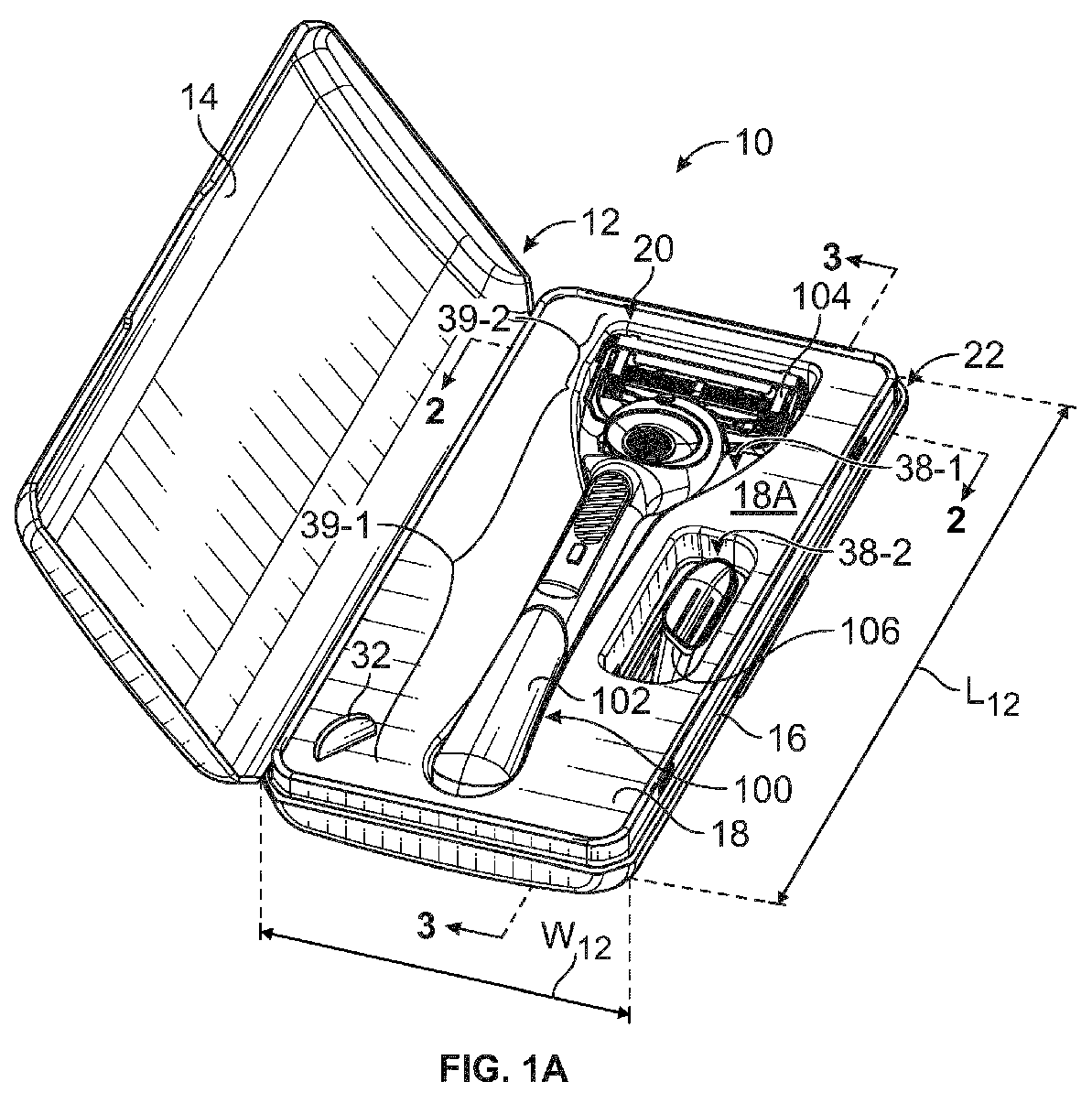
- the storage assembly 10 may comprise a case 12 with a top portion 14 and a bottom portion 16 and an insert 18 and 18' each comprising a respective front face 18A and 18A' and rear face 18B and 18B'.
- the inserts 18 and 18' may each comprise one or more respective cavities 38 and 38' configured to receive one or more components of a shaving razor system 20.
- the case 12 comprises a longitudinal length L 12 and a lateral width W 12 .
- the top and bottom portions 14 and 16 may comprise an engineering plastic, such as a polycarbonate, a metal, or a metal alloy, such as steel, aluminum, tin, or combinations thereof.
- the insert 18 and 18' may be removable, thus allowing for easy cleaning and drying of the inserts 18 and 18' and the case 12.
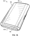
- the top and bottom portions 14 and 16 of the case 12 may be coupled together, e.g., by a hinge (not shown) so as to be movable relative to one another between an open position (see FIG. 1A ) and a closed position (see FIGS. 1B and 4 ).
- a section of the bottom portion 16 may be received in the top portion 14 when the case 12 is in the closed position.
- the bottom portion 16 may comprise side walls 16-1, 16-2, 16-3, and 16-4, and one or more of the side walls 16-1 to 16-4 may comprise an indent 22, in which a portion of the side wall(s) 16-1 to 16-4 extends inward toward an interior of the case 12.
- the indent 22 may extend around at least a section of the bottom portion 16.
- a section of the top portion 14 may extend over and be received in the indent 22 formed in the bottom portion 16.
- the top and bottom portions 14 and 16 may be secured together and the case 12 may be maintained in the closed position, at least in part, by an interference fit between the top and bottom portions 14 and 16.
- the bottom portion 16 of the case 12 defines a compartment 24 that is configured to removably receive a respective one of the inserts 18 and 18'.
- the compartment 24 is at least partially defined by the side walls 16-1 to 16-4 and a bottom wall 16-5 of the bottom portion 16 of the case 12.
- the bottom portion 16 of the case 12 may comprise a first peripheral edge 30 that extends away from one or more of the side walls 16-1 to 16-4 and at least partially defines a first periphery or a first opening 26 into which the insert 18 is introduced into the compartment 24. At least a portion of the peripheral edge 30 may define a first retainer 28 that extends over at least a portion of the insert 18 when the insert 18 is received in the compartment 24.
- the first retainer 28 may comprise structure separate from or in addition to the peripheral edge 30.
- the side walls 16-1 to 16-4 of the bottom portion 16 may terminate in rolled upper edges that extend inward toward each other so as to define the peripheral edge 30 and the first retainer 28 for the first compartment 24.
- the rolled upper edges of the bottom portion 16 extend over at least a portion of the insert 18, and outer edges 19 of the insert 18 contact the rolled upper edges of the bottom portion 16 to hold the insert 18 in place in the compartment 24.
- the bottom portion 16 of the case 12 may comprise an inwardly located second peripheral edge 30' that is defined by the indent 22 formed in the side walls 16-1 to 16-4 of the bottom portion 16.
- the second peripheral edge 30' may define a second periphery or a second opening 26' into which the insert 18' is introduced into the compartment 24.
- At least a portion of the second peripheral edge 30' may also define a second retainer 28' that extends over at least a portion of the insert 18' when the insert 18' is received in the compartment 24.
- the peripheral edge 30' may be defined by one or more inwardly extending portions of one or more of the side walls 16-1 to 16-4.
- the portion(s) of the side walls 16-1 to 16-4 defining the indent 22 and the second peripheral edge 30' extend over at least a portion of the insert 18', and outer edges 19' of the insert 18' contact the portion(s) of the side walls 16-1 to 16-4 to hold the insert 18' in place in the compartment 24.
- the retainers 28, 28' are depicted in FIGS. 2-4 as being substantially continuous and extending completely around the respective openings 26 and 26', it is understood that the retainers 28, 28' may be discontinuous and may comprise, for example, one or more discrete extensions or protrusions that extend away from one or more of the side walls 16-1 to 16-4 and over one or more portions of the inserts 18 and 18'.
- the outer edges 19 and 19' of the respective inserts 18 and 18' are depicted in FIGS. 2-4 as contacting the respective retainer 28 and 28' all the way around the openings 26 and 26', it is understood that the inserts 18 and 18' may comprise any desired shape and may contact only a portion of the respective retainer 28 and 28'.
- the inserts 18 and 18' may comprise one or more cutouts (not shown) to accommodate the hinge or other components of the case 12.
- the rear face 18B of the insert 18 may be substantially planar except for the one or more cavities 38 extending outward from the rear face 18B, and one or more portions of the cavities 38 may contact the bottom wall 16-5 of the bottom portion 16 and may act as a stabilizing feature to support the insert 18 and prevent the insert 18 from tilting or shifting in the compartment 24 of the bottom portion 16.
- a rear face 118B of the insert 118 may comprise a plurality of ribs 136A and 136B extending outward from the rear face 118B.
- the ribs 136A may extend laterally, i.e., across at least a portion of a width (not labeled; see FIG. 2 ) of the insert 118, and the ribs 136B may extend longitudinally, i.e., across at least a portion of a length (not labeled; see FIGS. 3 and 4 ) of the insert 118.
- the ribs 136A and 136B may act as stabilizing features to help to support and stabilize the insert 118 when the insert 118 is inserted into the case (see FIG. 4 ) and prevent the insert 118 from tilting or shifting in the compartment 24 of the bottom portion 16.
- the ribs 136A and 136B may optionally conform to a shape of at least a section of the bottom portion 16 of the case 12.
- the ribs 136A and 136B of the insert 118 shown in FIG. 7 are depicted as being curved, and this curvature may help to stabilize the insert 118 in the case 12 shown in FIG. 2 , in which at least a portion of the bottom wall 16-5 of the bottom portion 16 is curved.
- the bottom portion 16 may comprise any desirable shape (e.g., a shape in which the bottom wall 16-5 is substantially planar), and the inserts 18, 18', and 118' may comprise one or more stabilizing features (e.g., ribs, discrete extensions or feet, etc.) configured to conform to the shape of the bottom portion 16 and support and stabilize the insert 18, 18', and 118.
- the inserts 18, 18', and 118' may comprise one or more stabilizing features (e.g., ribs, discrete extensions or feet, etc.) configured to conform to the shape of the bottom portion 16 and support and stabilize the insert 18, 18', and 118.
- Inserts in accordance with the present disclosure may be sufficiently flexible and deformable to allow for repeated placement in, and removal from, the bottom portion 16 of the case 12 without damage to the insert.
- the inserts 18 and 18' shown in FIGS. 2-4 it is understood that all inserts described herein may comprise similar properties and features.
- the inserts 18 and 18' may be sufficiently flexible and deformable to allow for insertion of the inserts 18 and 18' through the respective opening 26 and 26' and into the compartment 24 defined in the bottom portion 16 of the case 12.
- the inserts 18 and 18' are also expandable to allow the inserts 18 and 18' to return to generally an original or initial shape so as to be retained in the compartment 24.
- the inserts 18 and 18' may comprise a deformable material having a Shore A hardness of between 40 and 70.
- the inserts 18 and 18' may comprise a material such as silicone or a thermoplastic elastomer.
- the inserts 18 and 18' may comprise at least one first dimension that is greater than a corresponding second dimension of the openings 26 and 26' of the compartment 24 into which the inserts 18 and 18' are received, as shown in FIGS. 2-4 .
- the insert 18 may comprise a width W 18 and a length L 18 , in which the width W 18 of the insert 18 is greater than a width W 26 of the opening 26 and/or the length L 18 of the insert 18 is greater than a length L 26 of the opening 26.
- the insert 18' may similarly comprise a length L 18' that is greater than a length L 26' of the opening 26'.
- the insert 18' may also comprise a width that is greater than a width of the opening 26'.
- the length L 18 , and L 18' and width W 18 may comprise a maximum length and width of the respective insert 18 and 18'.
- the length L 26 and L 26' and width W 26 may similarly comprise a maximum length and width of the respective opening 26 and 26'. It may be seen in FIGS. 2-4 that at least a portion of the compartment may comprise a length and/or width (not labeled) that is substantially similar to, or greater, than the length L 18 /L 18' and/or width W 18 of the respective inserts 18 and 18'.
- the inserts 18 and 18' may be deformed (i.e., crumpled, folded, bended, rolled, etc.) from an initial or "resting" state to a deformed state, such that at least one dimension, e.g., the width W 18 and/or length L 18 / L 18' , of the insert 18 and 18' is less than the corresponding dimension W 26 and/or L 26 /L 26' of the respective opening 26 and 26'.
- the deformed inserts 18 and 18' may then be inserted through the respective opening 26 and 26' into the compartment 24.
- the deformed inserts 18 and 18' may return to their initial or resting state with their initial respective shape and dimensions.
- the opening 26 defined by the rolled upper edges of the side walls 16-1 to 16-4 is smaller than the opening 26' defined by the indent 22 and that the insert 18' would also be sufficiently deformable to allow the insert 18' to be inserted past the rolled upper edges of the side walls 16-1 to 16-4.
- the outer edges 19 and 19' of the respective insert 18 and 18' contact and engage the respective retainer 28 and 28' to hold the inserts 18 and 18' in place in the compartment 24.
- the inserts 18 and 18' are also removable from the case 12 by grasping and deforming the inserts 18 and 18' from the initial or resting state to the deformed state, as described herein, and removing the deformed inserts 18 and 18' from the compartment 24 through the respective opening 26 and 26'. After removal from the compartment 24, the inserts 18 and 18' return to their initial or resting state with their initial respective shape and dimensions.
- the front face 18A of the insert 18 may optionally comprise one or more pull tabs 32 extending outward from the front face 18A in a direction that is substantially perpendicular to a plane (not labeled) defined by the front face 18A of the insert 18.
- the pull tab(s) 32 assist with grasping the insert 18 and allow for easy removal of the insert 18 from the bottom portion 16 of the case 12. For example, a user may remove the insert 18 by gripping the pull tab 32 and pulling the insert 18 out of the compartment 24 without the need to grasp any other portions of the insert 18.
- a height of the pull tab 32, as measured in a direction extending outward from the front face 18A, may be greater than a thickness of the pull tab 32.
- the pull tab(s) 32 may be placed at one or more suitable locations, such as, for example, near one or more corners of the insert 18 as shown in FIG. 1A . Although the pull tab 32 is shown with respect to the insert 18 of FIG. 1A , it is understood that the pull tab 32 may be used with any of the inserts described herein.
- the inserts 18 and 18' are sized so that when the inserts 18 and 18' are positioned in the compartment in the case 12, one or more sidewalls of the inserts 18 and 18' engage one or more corresponding side walls 16-1 to 16-4 of the bottom portion 16 of the case 12 so as to define a substantially watertight seal with the one or more corresponding side walls 16-1 to 16-4 of the bottom portion 16 of the case 12.
- the inserts 18 and 18' may optionally be free of any drainage openings that extend through a thickness (not shown; see T 18 in FIG. 6 ) of the inserts 18 and 18'.
- the watertight seal and/or lack of drainage openings helps to prevent water and/or other liquids from reaching the bottom portion 16 of the case 12.
- the case 12 may be used and/or stored in a wet environment and may be exposed to shaving cream, soap, and other personal care products.
- the case 12 is intended to be durable and reusable, and one or both of the top and bottom portions 14 and 16 of the case 12 may be metal. To prolong the useful life of the case 12, it may be desirable to limit or prevent introduction of water and other liquids into the bottom portion 16 to help prevent rust, corrosion, and other damage to the case 12.
- the inserts 18 and 18' may be manufactured by, for example, molding.
- the inserts 18 and 18' which are also intended to be durable and reusable, may comprise a material such as silicone or a thermoplastic elastomer that is substantially inert and resistant to damage by temperature and by water, soap, and/or other liquids that may contact the inserts 18 and 18' during use in a home environment.
- the material of the inserts 18 and 18' may further comprise a material that is resistant to microbial (e.g., bacterial and/or fungal) growth or may optionally be treated to incorporate one or more antimicrobial ingredients.
- the inserts 18 and 18' are also removable for cleaning separate from the case 12 to further help prevent damage to the case 12 due to contact with water or cleaning chemicals.
- the inserts 18 and 18' may be configured to receive one or more components of the shaving razor system 20.
- the shaving razor system 20 may comprise a shaving razor 100, which may comprise a razor handle 102 alone or with a razor cartridge 104 attached to the razor handle 102.
- the shaving razor system 20 may also comprise an additional razor cartridge 106 that is not attached to the razor handle 102.
- FIGS. 8 and 9 illustrate other examples of shaving razor systems 20.
- the shaving razor system 20 may comprise a shaving razor 100, along with a plurality of additional razor cartridges 106 that are not attached to the razor handle 102 (see FIG. 8 ) and/or one or more accessories (see FIG. 9 ) such as a tube 108 of shaving cream, soap, lotion, etc. and/or a brush 110 for applying shaving cream.
- the inserts 18, 18', 218, and 318 may each comprise one or more respective cavities 38, 38', 238, and 338 that are each configured to receive one of the components of the shaving razor system 20.
- the first and second inserts 18 and 18' may each comprise a respective first cavity 38-1 and 38-1' that extends into a main body of the respective insert 18 and 18' from a front face 18A and 18A' of the respective insert 18 and 18' and is configured to receive a shaving razor 100.
- the inserts 218 and 318 in FIGS. 8 and 9 may also comprise a respective first cavity 238-1 and 338-1 that extends inward from a front face 218A and 318A of the respective insert 218 and 318 and is configured to receive a shaving razor 100.
- the inserts 18, 218, and 318 may further comprise one or more respective second cavities 38-2, 238-2, and 338-2.
- the shape and/or dimensions of the one or more second cavities 38-2, 238-2, and 338-2 may be adjusted as desired to receive components of varying size and shape.
- the insert 18 may comprise a second cavity 38-2 that is configured to receive an additional razor cartridge 106 that is not attached to the razor handle 102. As shown in FIG.
- the second cavities 238-2 may all comprise a similar size and shape and may be configured for receiving one type of component, e.g., a plurality of additional razor cartridges 106.
- the insert 318 may comprise two or more second cavities 338-2 with different size(s) and/or shape(s) and may be configured for receiving different components.
- the second cavities 338-2 may each be configured to receive an accessory, such as a tube 108 and/or a brush 110.
- the insert 18' may also comprise, for example, at least one second cavity for receiving an additional razor cartridge 106 and/or accessory 108/110, as described herein.
- the dimensions and shape of the inserts 18, 18', 118, 218, 318 may be such that the inserts 18, 18', 118, 218, 318 are interchangeable and may all be used with the same case 12.
- a manufacturer may make a single type of case 12 and may manufacture different inserts 18, 18', 118, 218, 318 that may be used with the case 12.
- the inserts 18, 18', 118, 218, 318 may be interchangeable such that a user who purchases a case 12 with, for example, the insert 18 as shown in FIG. 1A , may purchase different inserts 18', 118, 218, 318 for use with the same case 12 to hold different shaving razor systems, accessories, etc.
- the cavities 38, 38', 238, and 338 may be positioned so as to maximize the number of components of the shaving razor system 20 that may be received in the respective inserts 18, 18', 218, and 318.
- the longitudinal length L 12 of the case 12 may be greater than the lateral width W 12 of the case 12, and the first and second cavities 38-1 and 38-2 may be arranged to maximize usage of space within the case 12.
- the first cavity 38-1 may comprise a first portion 39-1 that extends along at least a part of the longitudinal length L 12 of the case 12 and is configured to receive the razor handle 102; and a second portion 39-2 that extends along at least a part of the lateral width W 12 of the case 12 and is configured to receive the razor cartridge 104 attached to the razor handle 102.
- the second cavity 38-2 that is configured to receive the additional razor cartridge 106 may extend along at least a part of the lateral length L 12 of the case 12 and may be positioned transverse to a direction of the second portion 39-2 of the first cavity 38-1.
- the first cavity 38-1 may also define a first longitudinal axis A 1
- the second cavity 38-2 may define a second longitudinal axis A 2 that is parallel to the first longitudinal axis A 1 .
- the first cavity 38-1' in FIG. 4 may similarly comprise a first portion 39-1' that extends along at least a part of the longitudinal length (not shown; see L 12 in FIG. 1A ) of the case 12 and is configured to receive the razor handle 102; and a second portion 39-2' that is configured to receive the razor cartridge 104 attached to the razor handle 102.
- the first cavity 38-1' may define a first longitudinal axis (not shown; see A 1 in FIG. 2 ).
- the insert 18' may comprise a second cavity that is substantially similar to the second cavity 38-2 depicted in FIGS. 1A , 2 , and 3 and extends along at least a part of the lateral length (not shown; see L 12 in FIG. 1A ) of the case 12 transverse to a direction of the second portion 39-2' of the first cavity 38-1'.
- the first cavity 238-1 of the insert 218 may be shaped and sized so as to be substantially similar to either of the first cavities 38-1 or 38-1' shown in FIGS. 1A and 2-4 and may comprise a first portion (not labeled) that extends along at least a part of the longitudinal length (not labeled) of the case 12 and is configured to receive the razor handle 102; and a second portion (not labeled) that extends along at least a part of the lateral width (not labeled) of the case 12 and is configured to receive the razor cartridge 104 attached to the razor handle 102. Similar to the second cavity 38-2 in FIGS. 1A , 2 , and 3 , the second cavities 238-2 in FIG.
- each of which are configured to receive an additional razor cartridge 106 may extend along at least a part of the lateral length of the case 12 and may be positioned transverse to a direction of the second portion of the first cavity 238-1.
- the first cavity 238-1 may define a first longitudinal axis A 10 .
- the insert 218 may be configured such that a pair of second cavities 238-2 are located on each side of the first cavity 238-1.
- One pair of second cavities 238-2 may define a second longitudinal axis A 20-1
- the other pair of second cavities 238-2 may define a third longitudinal axis A 20-2 , in which the second and third longitudinal axes A 20-1 and A 20-2 are both parallel to the first longitudinal axis A 10 .
- the first cavity 338-1 of the insert 318 may be shaped and sized so as to be substantially similar to either of the first cavities 38-1 or 38-1' shown in FIGS. 1A and 2-4 and may comprise a first portion (not labeled) that extends along at least a part of the longitudinal length (not labeled) of the case 12 and is configured to receive the razor handle 102; and a second portion (not labeled) that extends along at least a part of the lateral width (not labeled) of the case 12 and is configured to receive the razor cartridge 104 attached to the razor handle 102. Similar to the second cavity 38-2 in FIGS. 1A , 2 , and 3 , the second cavities 338-2 in FIG.
- the first cavity 338-1 may define a first longitudinal axis (not shown; see A 1 and A 10 in FIGS. 2 and 8 ).
- the insert 318 may be configured such that the second cavities 338-2 are located on either side of the first cavity 338-1.
- One of the second cavities 338-2 e.g., the second cavity 338-2 configured to receive the tube 108) may define a second longitudinal axis (not shown; see A 2 and A 20-1 in FIGS.
- the other second cavity 338-2 (e.g., the second cavity 338-2 configured to receive the brush 110) may define a third longitudinal axis (not shown; see A 20-2 in FIG. 8 ), in which the second and third longitudinal axes defined by the second cavities 338-2 are both parallel to the first longitudinal axis defined by the first cavity 338-1.
- the insert 318 may optionally comprise a plurality of aeration slots 42 that extend partially through a thickness (not shown; see T 18 in FIG. 6 ) of the insert 318 and communicate with the first cavity 338-1.
- the aeration slots 42 may comprise a plurality of spaced-apart slots located near the razor cartridge 104 and may extend in a direction substantially parallel to a first longitudinal axis (not shown; see A 1 in FIG. 2 ) of the first cavity 338-1.
- the aeration slots 42 may help to remove excess moisture from the first cavity 338-1 and the razor cartridge 104 following use.
- each cavity 38, 38', 238, and 338 may be adjusted as desired so as to conform to the dimension(s), shape, etc. of at least a portion of the component of the shaving razor system 20 that the cavity 38, 38', 238, and 338 is configured to receive.
- the first and second portions 39-1 and 39-2 of the first cavity 38-1 may comprise a shape and dimensions that substantially correspond to the shape and dimensions of at least a portion of the razor handle 102 and the razor cartridge 104, respectively, as measured in a direction parallel to the length and width L 12 and W 12 of the case 12.
- the second cavity 38-2 may likewise comprise a shape and dimensions that substantially correspond to the shape and dimensions of at least a portion of the additional razor cartridge 106, as measured in a direction parallel to the length and width L 12 and W 12 of the case 12.
- the first and second cavities 38-1', 238-1, 338-1, 238-2, and 338-2 of the respective inserts 18', 218, and 318 in FIGS. 4 , 8 , and 9 may similarly comprise shapes and dimensions that substantially correspond to the shape and dimensions of at least a portion of the razor handle 102, the razor cartridge 104, the additional razor cartridge(s) 106, the tube 108, and/or the brush 110 that are received therein, as measured in a direction parallel to the length L 12 and width W 12 of the case 12 (see FIG. 1 ).
- a floor F 38-1 of the first cavity 38-1 may be substantially planar, and the first cavity 38-1 may comprise a substantially uniform depth D 38 along substantially an entirety of the first cavity 38-1.
- a depth D 38-1' of the first cavity 38-1' may vary along one or more sections of the first cavity 38-1'.
- a floor F 38-1' of the first cavity 38-1' may comprise one or more sections in the first portion 39-1' that are curved to correspond to a curvature and/or shape of the razor handle 102, such that the first cavity 38-1' supports the razor handle 102.
- the insert 18' may further comprise a support rib 40 that extends upward from the floor F 38-1' and into the first cavity 38-1'. The support rib 40 may extend across generally an entire width of the first portion 39-1' of the first cavity 38-1'.
- the razor cartridge 104 may be adjacent to and/or face the floor F 38-1' of the first cavity 38-1', and the support rib 40 may engage at least a portion of the razor handle 102 and/or the razor cartridge 104, such that substantially at least a portion of the razor cartridge 104 that is adjacent to/faces the floor F 38-1' is spaced apart from, i.e., spaced above, the floor F 38-1' of the first cavity 38-1'.
- the shaving razor 100 may be placed in the first cavity 38-1' with a protective overcap (not labeled; see 112 in FIG. 5 ) mounted to the razor cartridge 104 as shown in FIG.
- the support rib 40 engages a portion of the razor handle 102 and/or the razor cartridge 104 such that only a small portion of the razor cartridge 104, i.e., an outer edge of the protective overcap, contacts the floor F 38-1' of the first cavity 38-1'.
- at least 50% of the razor cartridge 104 facing the floor F 38-1' is spaced apart from the floor F 38-1' .
- at least 60%, at least 70%, at least 80%, at least 90%, at least 95%, or at least 99% of the razor cartridge 104 is spaced apart from the floor F 38-1' .
- the support rib 40 may engage the razor handle 102 and/or razor cartridge 104 such that an entirety of the razor cartridge (including the protective overcap) is spaced apart from the floor F 38-1 ,. It can be seen from FIG. 4 that when the shaving razor 100 is placed in the first cavity 38-1' without the protective overcap, engagement between the support rib 40 and the razor handle 102 and/or the razor cartridge 104 ensures that all parts of the razor cartridge 104 that are adjacent to and/or face the floor F 38-1' , e.g., the blade(s), lubrication strip(s), guard(s), etc., are spaced apart from and avoid contact with the floor F 38-1' of the first cavity 38-1'.
- the support rib 40 may also help to prevent unwanted side-to-side tilting motion of the razor handle 102 following placement of the shaving razor 100 in the first cavity 38-1'.
- the first cavities 238-1 and 338-1 depicted in FIGS. 8 and 9 may comprise a structure that is substantially similar to either of the first cavities 38-1 and 38-2 in FIGS. 2 and 4 .
- the second cavity 38-2 may similarly comprise a substantially uniform depth (not shown) or may comprise a depth that varies along one or more sections of the second cavity, as shown in FIGS. 3 , 5, and 6 .
- the second cavity 38-2 may be configured to receive an additional razor cartridge 106' with a protective overcap 112, as shown in FIG. 5 , or to receive the razor cartridge 106 alone (i.e., without the overcap 112), as shown in FIG. 3 , in which the razor cartridge 106, 106' is received at a different level within the second cavity 38-2 depending on whether the overcap 112 is present or absent.
- the insert 18 may comprise a first ledge 52 and a second ledge 56, each of which are positioned within the second cavity 38-2.
- the second cavity 38-2 may comprise a first section 50 defined by the first ledge 52 and first, second, third, and fourth side walls 50-1, 50-2, 50-3, and 50-4.
- the second cavity 38-2 may further comprise a second section 54 defined by the second ledge 56 and first, second, third, and fourth side walls (only first, second, and third side walls 54-1, 54-2, and 54-3 are visible).
- the first ledge 52 may comprise two discrete portions 52-1 and 52-2 located along a perimeter of the second cavity 38-2 in the first section 50.
- the second ledge 56 may be substantially continuous and may extend around an entirety of the perimeter of the second cavity 38-2 in the second section 54.
- the first ledge 52 may comprise a substantially continuous structure similar to the second ledge 56 and/or that the second ledge 56 may comprise two or more discrete portions similar to the first ledge 52.
- the first ledge 52 is configured to engage and support the overcap 112 when the overcap 112 is mounted to the razor cartridge 106'.
- the overcap 112 may comprise a hard plastic cover that fits over the razor cartridge 106' to protect it from damage and to protect a user from injury by inadvertent contact with blades (not visible; see 114 in FIG. 3 ) of the razor cartridge 106'.
- the overcap 112 and the razor cartridge 106' rest on a portion of the first ledge 52.
- the overcap 112 comprises outer ends 113A and 113B, and the first ledge 52 engages a portion 113A-1 and 113B-1 of each respective outer end 113A and 113B to support the overcap 112 and the razor cartridge 106'.
- the second ledge 56 is configured to directly engage and support the razor cartridge 106 when the overcap 112 is removed.
- the razor cartridge 106 rests on a portion of the second ledge 56.
- the razor cartridge 106 comprises outer edges 107A and 107B, and the second ledge 56 engages a portion 107A-1 and 107B-1 of each respective outer edge 107A and 107B to support the razor cartridge 106.
- the first and second ledges 52 and 56 are spaced apart from one another in a direction parallel to a thickness T 18 of the insert 18.
- the second ledge 56 may be located nearest to a floor F 38-2 of the second cavity 38-2, and the first ledge 52 is spaced apart from the second ledge 56 in a direction toward the front face 18A of the insert 18.
- first and second ledges 52 and 56 are both spaced apart from the floor F 38-2 of the second cavity 38-2.
- the first ledge 52 is spaced from the floor F 38-2 such that when the razor cartridge 106' with the overcap 112 is supported by the first ledge 52, the overcap 112 does not contact the floor F 38-2 of the second cavity 38-2.
- the second ledge 56 is also spaced from the floor F 38-2 such that when the razor cartridge 106 alone (without the overcap 112) is supported by the second ledge 56, the razor cartridge 106 does not contact the floor F 38-2 of the second cavity 38-2.
- the razor cartridge 106 is spaced apart from the floor F 38-2 of the second cavity 38-2, such that blades 114 of the razor cartridge 106 do not contact the floor F 38-2 .
- the second cavities 238-2 depicted in FIG. 8 for receiving additional razor cartridges 106 may comprise a structure that is substantially similar to the structure of the second cavity 38-2 as described herein.
- one or more of the components of the shaving razor system 20 may be held in their respective first and second cavities 38-1, 38-1', 238-1, 338-1, 38-2, 238-2, and 338-2 at least in part, by their own weight, and when the case 12 is in the closed position, a depth D 12 of the case 12 (see FIG. 4 ) may be configured such that the top portion 14 of the case 12 contacts at least a portion of one or more of the components.
- the first cavity 38-1' may be configured such that when the case 12 is in the closed position, an upper wall 14-1 of the top portion 14 of the case 12 contacts a portion of the razor handle 102 to hold the shaving razor 100 in place in the first cavity 38-1'.
- the first cavities 38-1, 238-1, and 338-1 depicted in FIGS. 1A , 8 , and 9 may similarly be configured such that the top portion 14 of the case 12 contacts at least a portion of the shaving razor 100 to hold the shaving razor 100 in place when the case 12 is in the closed position.
- the second cavities 38-2, 238-2, and 338-2 may also be configured such that the top portion 14 of the case 12 contacts at least a portion of the additional razor cartridges 106, the tube 108, and/or the brush 110 to hold the component(s) in place when the case 12 is in the closed position.
- the insert 18, 18', 218, 318 comprises a flexible and/or deformable material
- the insert 18, 18', 218, 318 may be configured/sized to compress or deform when the case 12 contacts the portion(s) of the component(s) of the shaving razor system 20 to hold the component(s) securely in place without damaging the component(s), the case 12, and/or the insert 18, 18', 218, 318.
- one or more portions of the cavities 38, 38', 238, and 338 may be configured to at least partially secure one or more of the components of the shaving razor system 20 using a friction or interference fit.
- the additional razor cartridge 106, 106' either alone or with the overcap 112 may be secured in the second cavity 38-2, at least in part, via an interference fit. As shown in FIGS.
- portions 51-1 and 51-2 of the first section 50 engage a portion 113A-2 and 113B-2 of the respective outer end 113A and 113B of the overcap 112 to hold the razor cartridge 106' and the overcap 112 in position in the first section 50 via an interference fit.
- These portions 51-1 and 51-2 that engage the outer ends 113A and 113B of the overcap 112 may be located at or near junctions of the third side wall 50-3 with the first and second side walls 50-1 and 50-2.
- portions of the first section 50 at or near junctions of the fourth side wall 50-4 (see FIG. 2 ) with the first and second side walls 50-1 and 50-2 may similarly engage portions of the outer ends 113A and 113B of the overcap 112 via an interference fit.
- portions 55-1 and 55-2 of the second section 54 engage a portion 107A-2 and 107B-2 of the respective outer edge 107A and 107B of the razor cartridge 106 to hold the razor cartridge 106 in position in the second section 54 via an interference fit.
- These portions 55-1 and 55-2 that engage the outer edges 107A and 107B of the razor cartridge 106 may be located at or near junctions of the third side wall 54-3 with the first and second side walls 54-1 and 54-2.
- portions of the second section 54 at or near junctions of the fourth side wall (not shown) with the first and second side walls 54-1 and 54-2 may similarly engage portions of the outer edges 107A and 107B of the razor cartridge 106 via an interference fit.
- one or more of the second cavities 238-2 shown in FIG. 8 for receiving additional razor cartridges 106 may comprise a structure that is substantially similar to the structure of the second cavity 38-2 as described herein.
- the first cavity 38-1, 38-1', 238-1, and 338-1 shown in FIGS. 1A , 2-4 , 8 , and 9 and one or more of the second cavities 338-2 in FIG. 9 may also be configured to receive at least a portion of the shaving razor 100 and/or the accessories 108/110 via an interference fit.
- one or more of the first and/or second cavities 38-1, 38-1', 238-1, 338-1 and 38-2, 238-2, 338-2 may comprise an undercut (not shown) that receives at least a portion of one or more of the components of the shaving razor system 20 via a snap fit.
- the storage assembly as described herein is intended to provide a compact, multi-use container that not only protects the components of the shaving razor system during shipping and serves as packaging in a retail environment, but also serves as a convenient storage and travel kit in a home environment.
- Inserts in accordance with the present disclosure are flexible and deformable for fast and easy removal from the case but are also robust enough to withstand the demands of repeated placement in, and removal from, the case without damage to the insert.
- the inserts may comprise a durable material that is easy to clean and can withstand exposure to water, soap, shaving cream, etc.
- the case and inserts may be cleaned separately to prolong their useful life.
- the assembly may also be configured to function with specific shaving razor systems or types thereof to ensure that the components of the shaving razor system fit securely in the insert and case.
- the inserts are robust enough to withstand repeated insertion and removal of the components of the shaving razor system without damage to the insert and without loss of the ability to retain the components of the shaving razor system in the cavities.
- the inserts comprise a flexible and/or deformable material, the insert is able to compress or deform when the closed case contacts one or more portions of the component(s) of the shaving razor system to hold the component(s) securely in place without damaging them, the case, and/or the insert.
- the case and inserts may be used to hold, organize, and store the razor handle, additional cartridge(s), and/or accessories for day-to-day use.
- the insert comprises a support rib
- the razor handle with attached razor cartridge may be placed in the first cavity without first installing a protective overcap, as the support rib ensures that the razor cartridge does not contact the floor of the first cavity.
- spare razor cartridges may be inserted into the second cavity with or without the protective overcap, as the two sections and corresponding ledges formed in the second cavity ensure that the razor cartridge is held securely in place and that the razor cartridge is free of contact with the floor of the second cavity.
- the inserts may be interchangeable such that multiple different inserts may be used with a single case.
- the inserts may include various cavity configurations for different shaving razor systems, accessories, etc. and may be manufactured to comprise a same general (outer) shape and dimensions so that all of the insert configurations may utilize a single case design. Users may purchase one case and multiple inserts with different configurations that may all be used with the same case.
- the case and inserts provide a sturdy and secure storage container and/or travel kit that protects the components of the shaving razor system from damage and protects adjacent items from damage caused by contact with one or more of the components of the shaving razor system.
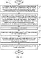
- FIGS. 10 and 11 are flow diagrams of methods 400 and 500 of assembling a storage assembly for a shaving razor system, in accordance with the present disclosure. Although reference is made to the storage assembly 10 shown in FIGS. 1A , 2 , and 3 , it is understood that the disclosed methods may be used with any of the embodiments described herein.
- the method 400 begins at Step 410 with providing an insert 18 comprising one or more cavities 38-1 and 38-2 that may be configured to receive one or more components of a shaving razor system 20.
- a case 12 comprising a top portion 14 and a bottom portion 16 is provided.
- the bottom portion 16 of the case 12 defines a compartment 24 configured to removably receive the insert 18, and the insert 18 comprises at least one first dimension L 18 and/or W 18 that is greater than a corresponding second dimension L 26 and/or W 26 of an opening 26 into the compartment 24.
- the method 400 continues at Step 430 with deforming the insert 18 and inserting the deformed insert 18 into the opening 26 of the compartment 24 at Step 440.
- the insert 18 is sufficiently flexible and deformable to allow for placement of the insert 18 (without damage) into the compartment 24 via the opening 26, which may be smaller than the insert 18.
- the insert 18 is deformed by crumpling, folding, bending, etc. and inserting the deformed insert 18 through the opening 26 and into the compartment 24.
- the insert 18 is also expandable to allow the insert 18 to return to generally an original or initial shape so as to be retained in the compartment 24.
- the shaving razor system 20 may comprise a shaving razor 100, which may comprise a razor handle 102 alone or with a razor cartridge 104 attached to the razor handle 102; one or more additional razor cartridges 106 that are not attached to the razor handle 102; and/or one or more accessories such as a tube 108 and/or a brush 110.
- the cavities 38-1 and 38-2 may be configured to receive a respective one of the components of the shaving razor system 20.
- the top and bottom portions 14 and 16 of the case 12 are secured together, after which the method 400 may conclude.
- top and bottom portions 14 and 16 of the case 12 may be coupled together so as to be movable relative to one another between an open position and a closed position, and the case 12 may be maintained in the closed position, at least in part, by an interference fit between at least a section of the top and bottom portions 14 and 16.
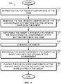
- FIG. 11 illustrates additional optional steps that may be performed following conclusion of the method 400 in FIG. 10 .
- the method 500 begins with separating the top and bottom portions 14 and 16 of the case 12 at Step 510, e.g., moving the case 12 from the closed position to the open position, and removing the one or more components of the shaving razor system 20 from the one or more cavities 38-1 and 38-2 in the insert 18 at Step 520.
- the method 500 continues at Step 530 with deforming the insert 18 sufficiently to remove the insert 18 from the compartment 24 of the bottom portion 16 of the case 12.
- the insert 18 is sufficiently flexible and deformable to allow for removal of the insert 18 (without damage) following insertion into the case 12, as described in the method 400.
- the insert 18 may be removed by grasping and deforming the insert 18, as described herein, and removing the deformed insert 18 from the compartment 24 through the opening 26.
- the insert 18 may optionally comprise one or more pull tabs 32 to assist with removal.
- the insert 18 is cleaned. As described herein, the insert 18 is removable from the case 12 so that the insert 18 and case 12 may be cleaned separately, which may help prevent damage to the (metal) case 12 due to contact with water, cleaning chemicals, etc.
- the method 500 continues with Step 550, in which the insert 18 is deformed sufficiently to insert it back into the opening 26 of the compartment 24.
- Step 560 the one or more components of the shaving razor system 20 are placed back into the one or more cavities 38-1 and 38-2 in the insert 18, after which the method 500 may conclude.
Landscapes
- Life Sciences & Earth Sciences (AREA)
- Forests & Forestry (AREA)
- Engineering & Computer Science (AREA)
- Mechanical Engineering (AREA)
- Packaging Of Annular Or Rod-Shaped Articles, Wearing Apparel, Cassettes, Or The Like (AREA)
Abstract
Description
- The invention generally relates to a storage assembly for a shaving razor system, and more particularly to an insert for storing one or more components of a shaving razor system.
- Conventional product packaging options for personal care products, such as shaving razors, include a significant amount of single-use plastic material that is discarded after the product is purchased. In recent years, consumers have become increasingly aware of the environmental impact of such product packaging and have begun to call for more sustainable and cost-effective packaging. Accordingly, newer packaging designs typically utilize paperboard (e.g., cardboard or molded pulp) boxes and/or inserts, which may be easily recycled. However, reusing has been determined to be a better alternative to recycling because it saves the energy that comes with having to collect, sort and re-manufacture products. It also significantly reduces waste and pollution because it reduces the need for raw materials and transportation saving both forests and water supplies.
- It would be desirable to provide durable, multi-use packaging for a shaving razor system that could be used both to display the product in a retail environment and store the product during consumer use resulting in minimum waste.
- In accordance with an aspect of the present disclosure, a storage assembly for a shaving razor system is provided that includes a case with a top portion and a bottom portion and an insert including a material having a Shore A hardness of between 40 and 70. The insert includes one or more cavities configured to receive one or more components of the shaving razor system, and the bottom portion of the case defines a compartment configured to removably receive the insert within the bottom portion.
- In accordance with another aspect of the present disclosure, a storage assembly for a shaving razor system is provided, in which the shaving razor system includes a razor cartridge either alone or in combination with a protective overcap and the assembly includes a case with a top portion and a bottom portion and an insert received in the bottom portion of the case. The insert includes a cavity configured to receive the razor cartridge either alone or with the protective overcap. The insert further includes a ledge positioned within the cavity and configured to engage and support the protective overcap when the protective overcap is mounted to the razor cartridge.
- In accordance with a further aspect of the present disclosure, a method of assembling a storage assembly for a shaving razor system is provided, the method including: providing an insert including a deformable material, in which the insert includes one or more cavities configured to receive one or more components of the shaving razor system; providing a case with a top portion and a bottom portion, in which the bottom portion of the case defines a compartment configured to removably receive the insert and the insert includes at least one first dimension that is greater than a corresponding second dimension of an opening into the compartment; deforming the insert; inserting the deformed insert into the opening of the compartment; placing the one or more components of the shaving razor system into the one or more cavities in the insert; and securing the top and bottom portions of the case together.
- While the specification concludes with claims particularly pointing out and distinctly claiming the subject matter which is regarded as forming the present invention, it is believed that the invention will be better understood from the following description which is taken in conjunction with the accompanying drawings in which like designations are used to designate substantially identical elements, and in which:
-
FIG. 1A is a perspective view of a storage assembly for a shaving razor system comprising a razor handle and a razor cartridge, in accordance with the present disclosure, in which a case is in an open position; -
FIG. 1B is a perspective view of the storage assembly ofFIG. 1A , in which the case is in a closed position; -
FIG. 2 is a perspective cross-sectional view taken along line 2-2 inFIG. 1A , in which the razor handle and a top portion of the case are removed; -
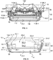
FIG. 3 is a perspective cross-sectional view taken along line 3-3 inFIG. 1A , in which the top portion of the case is removed and the razor cartridge is depicted without a protective overcap; -
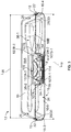
FIG. 4 is a cross-sectional view taken along line 4-4 inFIG. 1A ; -
FIG. 5 is a detailed perspective cross-sectional view similar toFIG. 4 , in which the razor cartridge is depicted with a protective overcap; -
FIG. 6 is a detailed perspective cross-sectional view similar toFIG. 5 , in which the razor cartridge is removed; -
FIG. 7 is a perspective view of a bottom of an insert for a shaving razor system, in accordance with the present disclosure; -
FIG. 8 is a top view of an additional storage assembly for a shaving razor system, in accordance with the present disclosure; -
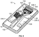
FIG. 9 is a perspective view of an additional storage assembly for a shaving razor system, in accordance with the present disclosure; and -
FIGS. 10 and11 are flow diagrams of methods of assembling a storage assembly for a shaving razor system, in accordance with the present disclosure. - Referring to
FIGS. 1A ,1B , and2-4 , astorage assembly 10 is illustrated. Thestorage assembly 10 may comprise acase 12 with atop portion 14 and abottom portion 16 and aninsert 18 and 18' each comprising a respectivefront face rear face inserts 18 and 18' may each comprise one or morerespective cavities 38 and 38' configured to receive one or more components of ashaving razor system 20. Thecase 12 comprises a longitudinal length L12 and a lateral width W12. The top andbottom portions insert 18 and 18' may be removable, thus allowing for easy cleaning and drying of theinserts 18 and 18' and thecase 12. - The top and
bottom portions case 12 may be coupled together, e.g., by a hinge (not shown) so as to be movable relative to one another between an open position (seeFIG. 1A ) and a closed position (seeFIGS. 1B and4 ). In some examples, a section of thebottom portion 16 may be received in thetop portion 14 when thecase 12 is in the closed position. As shown inFIGS. 2-4 , thebottom portion 16 may comprise side walls 16-1, 16-2, 16-3, and 16-4, and one or more of the side walls 16-1 to 16-4 may comprise anindent 22, in which a portion of the side wall(s) 16-1 to 16-4 extends inward toward an interior of thecase 12. Theindent 22 may extend around at least a section of thebottom portion 16. When thecase 12 is moved to the closed position, a section of thetop portion 14 may extend over and be received in theindent 22 formed in thebottom portion 16. The top andbottom portions case 12 may be maintained in the closed position, at least in part, by an interference fit between the top andbottom portions - The
bottom portion 16 of thecase 12 defines acompartment 24 that is configured to removably receive a respective one of theinserts 18 and 18'. With reference toFIGS. 2 and3 , thecompartment 24 is at least partially defined by the side walls 16-1 to 16-4 and a bottom wall 16-5 of thebottom portion 16 of thecase 12. Thebottom portion 16 of thecase 12 may comprise a firstperipheral edge 30 that extends away from one or more of the side walls 16-1 to 16-4 and at least partially defines a first periphery or afirst opening 26 into which theinsert 18 is introduced into thecompartment 24. At least a portion of theperipheral edge 30 may define afirst retainer 28 that extends over at least a portion of theinsert 18 when theinsert 18 is received in thecompartment 24. It is also contemplated that thefirst retainer 28 may comprise structure separate from or in addition to theperipheral edge 30. In the example shown inFIGS. 2 and3 , the side walls 16-1 to 16-4 of thebottom portion 16 may terminate in rolled upper edges that extend inward toward each other so as to define theperipheral edge 30 and thefirst retainer 28 for thefirst compartment 24. When theinsert 18 is received in thecompartment 24, the rolled upper edges of thebottom portion 16 extend over at least a portion of theinsert 18, andouter edges 19 of theinsert 18 contact the rolled upper edges of thebottom portion 16 to hold theinsert 18 in place in thecompartment 24. - With reference to
FIG. 4 , thebottom portion 16 of thecase 12 may comprise an inwardly located second peripheral edge 30' that is defined by theindent 22 formed in the side walls 16-1 to 16-4 of thebottom portion 16. The second peripheral edge 30' may define a second periphery or a second opening 26' into which the insert 18' is introduced into thecompartment 24. At least a portion of the second peripheral edge 30' may also define a second retainer 28' that extends over at least a portion of the insert 18' when the insert 18' is received in thecompartment 24. The peripheral edge 30' may be defined by one or more inwardly extending portions of one or more of the side walls 16-1 to 16-4. When the insert 18' is received in thecompartment 24, the portion(s) of the side walls 16-1 to 16-4 defining theindent 22 and the second peripheral edge 30' extend over at least a portion of the insert 18', andouter edges 19' of the insert 18' contact the portion(s) of the side walls 16-1 to 16-4 to hold the insert 18' in place in thecompartment 24. - Although the
respective retainers 28, 28' are depicted inFIGS. 2-4 as being substantially continuous and extending completely around therespective openings 26 and 26', it is understood that theretainers 28, 28' may be discontinuous and may comprise, for example, one or more discrete extensions or protrusions that extend away from one or more of the side walls 16-1 to 16-4 and over one or more portions of theinserts 18 and 18'. In addition, although theouter edges respective inserts 18 and 18' are depicted inFIGS. 2-4 as contacting therespective retainer 28 and 28' all the way around theopenings 26 and 26', it is understood that theinserts 18 and 18' may comprise any desired shape and may contact only a portion of therespective retainer 28 and 28'. For example, theinserts 18 and 18' may comprise one or more cutouts (not shown) to accommodate the hinge or other components of thecase 12. - In an example
first insert 18, as shown inFIGS. 2 and3 , therear face 18B of theinsert 18 may be substantially planar except for the one ormore cavities 38 extending outward from therear face 18B, and one or more portions of thecavities 38 may contact the bottom wall 16-5 of thebottom portion 16 and may act as a stabilizing feature to support theinsert 18 and prevent theinsert 18 from tilting or shifting in thecompartment 24 of thebottom portion 16. In another examplethird insert 118, as shown inFIG. 7 , arear face 118B of theinsert 118 may comprise a plurality ofribs rear face 118B. Theribs 136A may extend laterally, i.e., across at least a portion of a width (not labeled; seeFIG. 2 ) of theinsert 118, and theribs 136B may extend longitudinally, i.e., across at least a portion of a length (not labeled; seeFIGS. 3 and4 ) of theinsert 118. Theribs insert 118 when theinsert 118 is inserted into the case (seeFIG. 4 ) and prevent theinsert 118 from tilting or shifting in thecompartment 24 of thebottom portion 16. - The
ribs bottom portion 16 of thecase 12. For example, theribs insert 118 shown inFIG. 7 are depicted as being curved, and this curvature may help to stabilize theinsert 118 in thecase 12 shown inFIG. 2 , in which at least a portion of the bottom wall 16-5 of thebottom portion 16 is curved. It is understood that thebottom portion 16 may comprise any desirable shape (e.g., a shape in which the bottom wall 16-5 is substantially planar), and theinserts 18, 18', and 118' may comprise one or more stabilizing features (e.g., ribs, discrete extensions or feet, etc.) configured to conform to the shape of thebottom portion 16 and support and stabilize theinsert - Inserts in accordance with the present disclosure may be sufficiently flexible and deformable to allow for repeated placement in, and removal from, the
bottom portion 16 of thecase 12 without damage to the insert. Although the following discussion is provided with respect to theinserts 18 and 18' shown inFIGS. 2-4 , it is understood that all inserts described herein may comprise similar properties and features. With reference toFIGS. 2-4 , theinserts 18 and 18' may be sufficiently flexible and deformable to allow for insertion of theinserts 18 and 18' through therespective opening 26 and 26' and into thecompartment 24 defined in thebottom portion 16 of thecase 12. Theinserts 18 and 18' are also expandable to allow theinserts 18 and 18' to return to generally an original or initial shape so as to be retained in thecompartment 24. In some examples, theinserts 18 and 18' may comprise a deformable material having a Shore A hardness of between 40 and 70. In other examples, theinserts 18 and 18' may comprise a material such as silicone or a thermoplastic elastomer. - In some examples, the
inserts 18 and 18' may comprise at least one first dimension that is greater than a corresponding second dimension of theopenings 26 and 26' of thecompartment 24 into which theinserts 18 and 18' are received, as shown inFIGS. 2-4 . For instance, with reference toFIGS. 2 and3 , theinsert 18 may comprise a width W18 and a length L18, in which the width W18 of theinsert 18 is greater than a width W26 of theopening 26 and/or the length L18 of theinsert 18 is greater than a length L26 of theopening 26. As shown inFIG. 4 , the insert 18' may similarly comprise a length L18' that is greater than a length L26' of the opening 26'. Although not visible inFIG. 4 , the insert 18' may also comprise a width that is greater than a width of the opening 26'. In some examples, the length L18, and L18' and width W18 may comprise a maximum length and width of therespective insert 18 and 18'. The length L26 and L26' and width W26 may similarly comprise a maximum length and width of therespective opening 26 and 26'. It may be seen inFIGS. 2-4 that at least a portion of the compartment may comprise a length and/or width (not labeled) that is substantially similar to, or greater, than the length L18/L18' and/or width W18 of therespective inserts 18 and 18'. - To place the
inserts 18 and 18' in thecompartment 24, theinserts 18 and 18' may be deformed (i.e., crumpled, folded, bended, rolled, etc.) from an initial or "resting" state to a deformed state, such that at least one dimension, e.g., the width W18 and/or length L18/ L18', of theinsert 18 and 18' is less than the corresponding dimension W26 and/or L26/L26' of therespective opening 26 and 26'. The deformed inserts 18 and 18' may then be inserted through therespective opening 26 and 26' into thecompartment 24. Upon release inside thecompartment 24, thedeformed inserts 18 and 18' may return to their initial or resting state with their initial respective shape and dimensions. With reference toFIGS. 3 and4 , it is noted that theopening 26 defined by the rolled upper edges of the side walls 16-1 to 16-4 is smaller than the opening 26' defined by theindent 22 and that the insert 18' would also be sufficiently deformable to allow the insert 18' to be inserted past the rolled upper edges of the side walls 16-1 to 16-4. As shown inFIGS. 2-4 and described above, theouter edges respective insert 18 and 18' contact and engage therespective retainer 28 and 28' to hold theinserts 18 and 18' in place in thecompartment 24. Theinserts 18 and 18' are also removable from thecase 12 by grasping and deforming theinserts 18 and 18' from the initial or resting state to the deformed state, as described herein, and removing thedeformed inserts 18 and 18' from thecompartment 24 through therespective opening 26 and 26'. After removal from thecompartment 24, theinserts 18 and 18' return to their initial or resting state with their initial respective shape and dimensions. - As shown in
FIG. 1A , thefront face 18A of theinsert 18 may optionally comprise one ormore pull tabs 32 extending outward from thefront face 18A in a direction that is substantially perpendicular to a plane (not labeled) defined by thefront face 18A of theinsert 18. The pull tab(s) 32 assist with grasping theinsert 18 and allow for easy removal of theinsert 18 from thebottom portion 16 of thecase 12. For example, a user may remove theinsert 18 by gripping thepull tab 32 and pulling theinsert 18 out of thecompartment 24 without the need to grasp any other portions of theinsert 18. A height of thepull tab 32, as measured in a direction extending outward from thefront face 18A, may be greater than a thickness of thepull tab 32. The pull tab(s) 32 may be placed at one or more suitable locations, such as, for example, near one or more corners of theinsert 18 as shown inFIG. 1A . Although thepull tab 32 is shown with respect to theinsert 18 ofFIG. 1A , it is understood that thepull tab 32 may be used with any of the inserts described herein. - With continued reference to
FIGS. 2-4 , in some examples, theinserts 18 and 18' are sized so that when theinserts 18 and 18' are positioned in the compartment in thecase 12, one or more sidewalls of theinserts 18 and 18' engage one or more corresponding side walls 16-1 to 16-4 of thebottom portion 16 of thecase 12 so as to define a substantially watertight seal with the one or more corresponding side walls 16-1 to 16-4 of thebottom portion 16 of thecase 12. In other examples, theinserts 18 and 18' may optionally be free of any drainage openings that extend through a thickness (not shown; see T18 inFIG. 6 ) of theinserts 18 and 18'. The watertight seal and/or lack of drainage openings helps to prevent water and/or other liquids from reaching thebottom portion 16 of thecase 12. As described herein, because theinsert 18 and 18' is for receiving one or more components of a shavingrazor system 20, thecase 12 may be used and/or stored in a wet environment and may be exposed to shaving cream, soap, and other personal care products. Thecase 12 is intended to be durable and reusable, and one or both of the top andbottom portions case 12 may be metal. To prolong the useful life of thecase 12, it may be desirable to limit or prevent introduction of water and other liquids into thebottom portion 16 to help prevent rust, corrosion, and other damage to thecase 12. - The
inserts 18 and 18' may be manufactured by, for example, molding. Theinserts 18 and 18', which are also intended to be durable and reusable, may comprise a material such as silicone or a thermoplastic elastomer that is substantially inert and resistant to damage by temperature and by water, soap, and/or other liquids that may contact theinserts 18 and 18' during use in a home environment. The material of theinserts 18 and 18' may further comprise a material that is resistant to microbial (e.g., bacterial and/or fungal) growth or may optionally be treated to incorporate one or more antimicrobial ingredients. Theinserts 18 and 18' are also removable for cleaning separate from thecase 12 to further help prevent damage to thecase 12 due to contact with water or cleaning chemicals. - With reference to
FIGS. 1A and2-4 , theinserts 18 and 18' may be configured to receive one or more components of the shavingrazor system 20. In one example, the shavingrazor system 20 may comprise a shavingrazor 100, which may comprise arazor handle 102 alone or with arazor cartridge 104 attached to therazor handle 102. The shavingrazor system 20 may also comprise anadditional razor cartridge 106 that is not attached to therazor handle 102.FIGS. 8 and9 illustrate other examples of shavingrazor systems 20. As shown inFIGS. 8 and9 , the shavingrazor system 20 may comprise a shavingrazor 100, along with a plurality ofadditional razor cartridges 106 that are not attached to the razor handle 102 (seeFIG. 8 ) and/or one or more accessories (seeFIG. 9 ) such as atube 108 of shaving cream, soap, lotion, etc. and/or abrush 110 for applying shaving cream. - As shown in
FIGS. 1A ,2-4 ,8 , and9 , theinserts respective cavities 38, 38', 238, and 338 that are each configured to receive one of the components of the shavingrazor system 20. With reference toFIGS. 1A and2-4 , the first andsecond inserts 18 and 18' may each comprise a respective first cavity 38-1 and 38-1' that extends into a main body of therespective insert 18 and 18' from afront face respective insert 18 and 18' and is configured to receive a shavingrazor 100. Theinserts FIGS. 8 and9 may also comprise a respective first cavity 238-1 and 338-1 that extends inward from afront face respective insert razor 100. - With reference to
FIGS. 1A ,2 ,3 ,8 , and9 , theinserts FIGS. 1A ,2 , and3 , theinsert 18 may comprise a second cavity 38-2 that is configured to receive anadditional razor cartridge 106 that is not attached to therazor handle 102. As shown inFIG. 8 , when theinsert 218 comprises two or more second cavities 238-2, the second cavities 238-2 may all comprise a similar size and shape and may be configured for receiving one type of component, e.g., a plurality ofadditional razor cartridges 106. As shown inFIGS. 9 , theinsert 318 may comprise two or more second cavities 338-2 with different size(s) and/or shape(s) and may be configured for receiving different components. For example, the second cavities 338-2 may each be configured to receive an accessory, such as atube 108 and/or abrush 110. Although not visible inFIG. 4 , it is understood that the insert 18' may also comprise, for example, at least one second cavity for receiving anadditional razor cartridge 106 and/oraccessory 108/110, as described herein. - As shown in
FIGS. 1A ,4 , and7-9 , the dimensions and shape of theinserts inserts same case 12. For example, a manufacturer may make a single type ofcase 12 and may manufacturedifferent inserts case 12. In addition, theinserts case 12 with, for example, theinsert 18 as shown inFIG. 1A , may purchasedifferent inserts same case 12 to hold different shaving razor systems, accessories, etc. - The
cavities 38, 38', 238, and 338 may be positioned so as to maximize the number of components of the shavingrazor system 20 that may be received in therespective inserts FIGS. 1A ,2 , and3 , the longitudinal length L12 of thecase 12 may be greater than the lateral width W12 of thecase 12, and the first and second cavities 38-1 and 38-2 may be arranged to maximize usage of space within thecase 12. For example, the first cavity 38-1 may comprise a first portion 39-1 that extends along at least a part of the longitudinal length L12 of thecase 12 and is configured to receive the razor handle 102; and a second portion 39-2 that extends along at least a part of the lateral width W12 of thecase 12 and is configured to receive therazor cartridge 104 attached to therazor handle 102. As shown inFIGS. 1A ,2 , and3 , the second cavity 38-2 that is configured to receive theadditional razor cartridge 106 may extend along at least a part of the lateral length L12 of thecase 12 and may be positioned transverse to a direction of the second portion 39-2 of the first cavity 38-1. As shown inFIG. 2 , the first cavity 38-1 may also define a first longitudinal axis A1, and the second cavity 38-2 may define a second longitudinal axis A2 that is parallel to the first longitudinal axis A1. - The first cavity 38-1' in
FIG. 4 may similarly comprise a first portion 39-1' that extends along at least a part of the longitudinal length (not shown; see L12 inFIG. 1A ) of thecase 12 and is configured to receive the razor handle 102; and a second portion 39-2' that is configured to receive therazor cartridge 104 attached to therazor handle 102. The first cavity 38-1' may define a first longitudinal axis (not shown; see A1 inFIG. 2 ). Although not visible inFIG. 4 , the insert 18' may comprise a second cavity that is substantially similar to the second cavity 38-2 depicted inFIGS. 1A ,2 , and3 and extends along at least a part of the lateral length (not shown; see L12 inFIG. 1A ) of thecase 12 transverse to a direction of the second portion 39-2' of the first cavity 38-1'. - With reference to
FIG. 8 , the first cavity 238-1 of theinsert 218 may be shaped and sized so as to be substantially similar to either of the first cavities 38-1 or 38-1' shown inFIGS. 1A and2-4 and may comprise a first portion (not labeled) that extends along at least a part of the longitudinal length (not labeled) of thecase 12 and is configured to receive the razor handle 102; and a second portion (not labeled) that extends along at least a part of the lateral width (not labeled) of thecase 12 and is configured to receive therazor cartridge 104 attached to therazor handle 102. Similar to the second cavity 38-2 inFIGS. 1A ,2 , and3 , the second cavities 238-2 inFIG. 8 , each of which are configured to receive anadditional razor cartridge 106, may extend along at least a part of the lateral length of thecase 12 and may be positioned transverse to a direction of the second portion of the first cavity 238-1. The first cavity 238-1 may define a first longitudinal axis A10. Theinsert 218 may be configured such that a pair of second cavities 238-2 are located on each side of the first cavity 238-1. One pair of second cavities 238-2 may define a second longitudinal axis A20-1, and the other pair of second cavities 238-2 may define a third longitudinal axis A20-2, in which the second and third longitudinal axes A20-1 and A20-2 are both parallel to the first longitudinal axis A10. - With reference to
FIG. 9 , the first cavity 338-1 of theinsert 318 may be shaped and sized so as to be substantially similar to either of the first cavities 38-1 or 38-1' shown inFIGS. 1A and2-4 and may comprise a first portion (not labeled) that extends along at least a part of the longitudinal length (not labeled) of thecase 12 and is configured to receive the razor handle 102; and a second portion (not labeled) that extends along at least a part of the lateral width (not labeled) of thecase 12 and is configured to receive therazor cartridge 104 attached to therazor handle 102. Similar to the second cavity 38-2 inFIGS. 1A ,2 , and3 , the second cavities 338-2 inFIG. 9 may extend along at least a part of the lateral length of thecase 12 and may be positioned transverse to a direction of the second portion of the first cavity 338-1. The first cavity 338-1 may define a first longitudinal axis (not shown; see A1 and A10 inFIGS. 2 and8 ). Theinsert 318 may be configured such that the second cavities 338-2 are located on either side of the first cavity 338-1. One of the second cavities 338-2 (e.g., the second cavity 338-2 configured to receive the tube 108) may define a second longitudinal axis (not shown; see A2 and A20-1 inFIGS. 2 and8 ) and the other second cavity 338-2 (e.g., the second cavity 338-2 configured to receive the brush 110) may define a third longitudinal axis (not shown; see A20-2 inFIG. 8 ), in which the second and third longitudinal axes defined by the second cavities 338-2 are both parallel to the first longitudinal axis defined by the first cavity 338-1. - With continued reference to
FIG. 9 , theinsert 318 may optionally comprise a plurality ofaeration slots 42 that extend partially through a thickness (not shown; see T18 inFIG. 6 ) of theinsert 318 and communicate with the first cavity 338-1. Theaeration slots 42 may comprise a plurality of spaced-apart slots located near therazor cartridge 104 and may extend in a direction substantially parallel to a first longitudinal axis (not shown; see A1 inFIG. 2 ) of the first cavity 338-1. Theaeration slots 42 may help to remove excess moisture from the first cavity 338-1 and therazor cartridge 104 following use. - The dimension(s), shape, and the like of at least a portion of each
cavity 38, 38', 238, and 338 may be adjusted as desired so as to conform to the dimension(s), shape, etc. of at least a portion of the component of the shavingrazor system 20 that thecavity 38, 38', 238, and 338 is configured to receive. For example, with reference toFIGS. 1A and2 , the first and second portions 39-1 and 39-2 of the first cavity 38-1 may comprise a shape and dimensions that substantially correspond to the shape and dimensions of at least a portion of the razor handle 102 and therazor cartridge 104, respectively, as measured in a direction parallel to the length and width L12 and W12 of thecase 12. The second cavity 38-2 may likewise comprise a shape and dimensions that substantially correspond to the shape and dimensions of at least a portion of theadditional razor cartridge 106, as measured in a direction parallel to the length and width L12 and W12 of thecase 12. The first and second cavities 38-1', 238-1, 338-1, 238-2, and 338-2 of therespective inserts FIGS. 4 ,8 , and9 may similarly comprise shapes and dimensions that substantially correspond to the shape and dimensions of at least a portion of the razor handle 102, therazor cartridge 104, the additional razor cartridge(s) 106, thetube 108, and/or thebrush 110 that are received therein, as measured in a direction parallel to the length L12 and width W12 of the case 12 (seeFIG. 1 ). - In some examples, as shown in
FIG. 2 , a floor F38-1 of the first cavity 38-1 may be substantially planar, and the first cavity 38-1 may comprise a substantially uniform depth D38 along substantially an entirety of the first cavity 38-1. In other examples, as shown inFIG. 4 , a depth D38-1' of the first cavity 38-1' may vary along one or more sections of the first cavity 38-1'. In particular, a floor F38-1' of the first cavity 38-1' may comprise one or more sections in the first portion 39-1' that are curved to correspond to a curvature and/or shape of the razor handle 102, such that the first cavity 38-1' supports therazor handle 102. The insert 18' may further comprise asupport rib 40 that extends upward from the floor F38-1' and into the first cavity 38-1'. Thesupport rib 40 may extend across generally an entire width of the first portion 39-1' of the first cavity 38-1'. - As shown in
FIG. 4 , therazor cartridge 104 may be adjacent to and/or face the floor F38-1' of the first cavity 38-1', and thesupport rib 40 may engage at least a portion of the razor handle 102 and/or therazor cartridge 104, such that substantially at least a portion of therazor cartridge 104 that is adjacent to/faces the floor F38-1' is spaced apart from, i.e., spaced above, the floor F38-1' of the first cavity 38-1'. Following use, the shavingrazor 100 may be placed in the first cavity 38-1' with a protective overcap (not labeled; see 112 inFIG. 5 ) mounted to therazor cartridge 104 as shown inFIG. 4 , and thesupport rib 40 engages a portion of the razor handle 102 and/or therazor cartridge 104 such that only a small portion of therazor cartridge 104, i.e., an outer edge of the protective overcap, contacts the floor F38-1' of the first cavity 38-1'. In some examples, at least 50% of therazor cartridge 104 facing the floor F38-1' is spaced apart from the floor F38-1'. In other examples, at least 60%, at least 70%, at least 80%, at least 90%, at least 95%, or at least 99% of therazor cartridge 104 is spaced apart from the floor F38-1'. In other examples, thesupport rib 40 may engage the razor handle 102 and/orrazor cartridge 104 such that an entirety of the razor cartridge (including the protective overcap) is spaced apart from the floor F38-1,. It can be seen fromFIG. 4 that when the shavingrazor 100 is placed in the first cavity 38-1' without the protective overcap, engagement between thesupport rib 40 and the razor handle 102 and/or therazor cartridge 104 ensures that all parts of therazor cartridge 104 that are adjacent to and/or face the floor F38-1', e.g., the blade(s), lubrication strip(s), guard(s), etc., are spaced apart from and avoid contact with the floor F38-1' of the first cavity 38-1'. Thesupport rib 40 may also help to prevent unwanted side-to-side tilting motion of the razor handle 102 following placement of the shavingrazor 100 in the first cavity 38-1'. The first cavities 238-1 and 338-1 depicted inFIGS. 8 and9 may comprise a structure that is substantially similar to either of the first cavities 38-1 and 38-2 inFIGS. 2 and4 . - The second cavity 38-2 may similarly comprise a substantially uniform depth (not shown) or may comprise a depth that varies along one or more sections of the second cavity, as shown in
FIGS. 3 ,5, and 6 . In particular, the second cavity 38-2 may be configured to receive an additional razor cartridge 106' with aprotective overcap 112, as shown inFIG. 5 , or to receive therazor cartridge 106 alone (i.e., without the overcap 112), as shown inFIG. 3 , in which therazor cartridge 106, 106' is received at a different level within the second cavity 38-2 depending on whether theovercap 112 is present or absent. Theinsert 18 may comprise afirst ledge 52 and asecond ledge 56, each of which are positioned within the second cavity 38-2. With reference toFIGS. 2 ,5, and 6 , the second cavity 38-2 may comprise afirst section 50 defined by thefirst ledge 52 and first, second, third, and fourth side walls 50-1, 50-2, 50-3, and 50-4. With reference toFIGS. 3 and6 , the second cavity 38-2 may further comprise asecond section 54 defined by thesecond ledge 56 and first, second, third, and fourth side walls (only first, second, and third side walls 54-1, 54-2, and 54-3 are visible). - As shown in
FIG. 6 , thefirst ledge 52 may comprise two discrete portions 52-1 and 52-2 located along a perimeter of the second cavity 38-2 in thefirst section 50. Thesecond ledge 56 may be substantially continuous and may extend around an entirety of the perimeter of the second cavity 38-2 in thesecond section 54. Although not shown, it is understood that thefirst ledge 52 may comprise a substantially continuous structure similar to thesecond ledge 56 and/or that thesecond ledge 56 may comprise two or more discrete portions similar to thefirst ledge 52. - With reference to
FIGS. 5 and 6 , thefirst ledge 52 is configured to engage and support theovercap 112 when theovercap 112 is mounted to the razor cartridge 106'. Theovercap 112 may comprise a hard plastic cover that fits over the razor cartridge 106' to protect it from damage and to protect a user from injury by inadvertent contact with blades (not visible; see 114 inFIG. 3 ) of the razor cartridge 106'. When the razor cartridge 106' with theovercap 112 is received in the second cavity 38-2, theovercap 112 and the razor cartridge 106' rest on a portion of thefirst ledge 52. In particular, theovercap 112 comprisesouter ends first ledge 52 engages aportion 113A-1 and 113B-1 of each respectiveouter end overcap 112 and the razor cartridge 106'. - With reference to
FIGS. 3 and6 , thesecond ledge 56 is configured to directly engage and support therazor cartridge 106 when theovercap 112 is removed. When therazor cartridge 106 without theovercap 112 is received in the second cavity 38-2, therazor cartridge 106 rests on a portion of thesecond ledge 56. In particular, therazor cartridge 106 comprisesouter edges second ledge 56 engages aportion 107A-1 and 107B-1 of each respectiveouter edge razor cartridge 106. - As shown in
FIGS. 3 ,5, and 6 , the first andsecond ledges insert 18. Thesecond ledge 56 may be located nearest to a floor F38-2 of the second cavity 38-2, and thefirst ledge 52 is spaced apart from thesecond ledge 56 in a direction toward thefront face 18A of theinsert 18. Thus, when received in the second cavity 38-2, therazor cartridge 106 alone (i.e., without the overcap 112) is held at a position that is lower and closer to the floor F38-2, as compared to a position at which the razor cartridge 106' with theovercap 112 is held. - In addition, the first and
second ledges first ledge 52 is spaced from the floor F38-2 such that when the razor cartridge 106' with theovercap 112 is supported by thefirst ledge 52, theovercap 112 does not contact the floor F38-2 of the second cavity 38-2. Thesecond ledge 56 is also spaced from the floor F38-2 such that when therazor cartridge 106 alone (without the overcap 112) is supported by thesecond ledge 56, therazor cartridge 106 does not contact the floor F38-2 of the second cavity 38-2. In particular, therazor cartridge 106 is spaced apart from the floor F38-2 of the second cavity 38-2, such thatblades 114 of therazor cartridge 106 do not contact the floor F38-2. Although not shown, it is understood that the second cavities 238-2 depicted inFIG. 8 for receivingadditional razor cartridges 106 may comprise a structure that is substantially similar to the structure of the second cavity 38-2 as described herein. - In some examples, one or more of the components of the shaving
razor system 20 may be held in their respective first and second cavities 38-1, 38-1', 238-1, 338-1, 38-2, 238-2, and 338-2 at least in part, by their own weight, and when thecase 12 is in the closed position, a depth D12 of the case 12 (seeFIG. 4 ) may be configured such that thetop portion 14 of thecase 12 contacts at least a portion of one or more of the components. For example, as shown inFIG. 4 , the first cavity 38-1' may be configured such that when thecase 12 is in the closed position, an upper wall 14-1 of thetop portion 14 of thecase 12 contacts a portion of the razor handle 102 to hold the shavingrazor 100 in place in the first cavity 38-1'. The first cavities 38-1, 238-1, and 338-1 depicted inFIGS. 1A ,8 , and9 may similarly be configured such that thetop portion 14 of thecase 12 contacts at least a portion of the shavingrazor 100 to hold the shavingrazor 100 in place when thecase 12 is in the closed position. The second cavities 38-2, 238-2, and 338-2 may also be configured such that thetop portion 14 of thecase 12 contacts at least a portion of theadditional razor cartridges 106, thetube 108, and/or thebrush 110 to hold the component(s) in place when thecase 12 is in the closed position. Because theinsert insert case 12 contacts the portion(s) of the component(s) of the shavingrazor system 20 to hold the component(s) securely in place without damaging the component(s), thecase 12, and/or theinsert - In other examples, one or more portions of the
cavities 38, 38', 238, and 338 may be configured to at least partially secure one or more of the components of the shavingrazor system 20 using a friction or interference fit. For example, with reference toFIGS. 3 ,5 and 6 , theadditional razor cartridge 106, 106' either alone or with theovercap 112 may be secured in the second cavity 38-2, at least in part, via an interference fit. As shown inFIGS. 5 and 6 , when the razor cartridge 106' with theovercap 112 is inserted into the second cavity 38-2 and rests on thefirst ledge 52, portions 51-1 and 51-2 of thefirst section 50 engage aportion 113A-2 and 113B-2 of the respectiveouter end overcap 112 to hold the razor cartridge 106' and theovercap 112 in position in thefirst section 50 via an interference fit. These portions 51-1 and 51-2 that engage the outer ends 113A and 113B of theovercap 112 may be located at or near junctions of the third side wall 50-3 with the first and second side walls 50-1 and 50-2. Although not visible inFIGS. 5 and 6 , portions of thefirst section 50 at or near junctions of the fourth side wall 50-4 (seeFIG. 2 ) with the first and second side walls 50-1 and 50-2 may similarly engage portions of the outer ends 113A and 113B of theovercap 112 via an interference fit. - As shown in
FIGS. 3 and6 , when therazor cartridge 106 without theovercap 112 is inserted into the second cavity 38-2 and therazor cartridge 106 rests on thesecond ledge 56, portions 55-1 and 55-2 of thesecond section 54 engage aportion 107A-2 and 107B-2 of the respectiveouter edge razor cartridge 106 to hold therazor cartridge 106 in position in thesecond section 54 via an interference fit. These portions 55-1 and 55-2 that engage theouter edges razor cartridge 106 may be located at or near junctions of the third side wall 54-3 with the first and second side walls 54-1 and 54-2. Although not visible inFIGS. 3 and6 , portions of thesecond section 54 at or near junctions of the fourth side wall (not shown) with the first and second side walls 54-1 and 54-2 may similarly engage portions of theouter edges razor cartridge 106 via an interference fit. - Although not shown, it is understood that one or more of the second cavities 238-2 shown in
FIG. 8 for receivingadditional razor cartridges 106 may comprise a structure that is substantially similar to the structure of the second cavity 38-2 as described herein. The first cavity 38-1, 38-1', 238-1, and 338-1 shown inFIGS. 1A ,2-4 ,8 , and9 and one or more of the second cavities 338-2 inFIG. 9 may also be configured to receive at least a portion of the shavingrazor 100 and/or theaccessories 108/110 via an interference fit. Alternatively, or in addition, one or more of the first and/or second cavities 38-1, 38-1', 238-1, 338-1 and 38-2, 238-2, 338-2 may comprise an undercut (not shown) that receives at least a portion of one or more of the components of the shavingrazor system 20 via a snap fit. - The storage assembly as described herein is intended to provide a compact, multi-use container that not only protects the components of the shaving razor system during shipping and serves as packaging in a retail environment, but also serves as a convenient storage and travel kit in a home environment. Inserts in accordance with the present disclosure are flexible and deformable for fast and easy removal from the case but are also robust enough to withstand the demands of repeated placement in, and removal from, the case without damage to the insert. The inserts may comprise a durable material that is easy to clean and can withstand exposure to water, soap, shaving cream, etc. The case and inserts may be cleaned separately to prolong their useful life. The assembly may also be configured to function with specific shaving razor systems or types thereof to ensure that the components of the shaving razor system fit securely in the insert and case. The inserts are robust enough to withstand repeated insertion and removal of the components of the shaving razor system without damage to the insert and without loss of the ability to retain the components of the shaving razor system in the cavities. In addition, because the inserts comprise a flexible and/or deformable material, the insert is able to compress or deform when the closed case contacts one or more portions of the component(s) of the shaving razor system to hold the component(s) securely in place without damaging them, the case, and/or the insert.
- The case and inserts may be used to hold, organize, and store the razor handle, additional cartridge(s), and/or accessories for day-to-day use. In configurations in which the insert comprises a support rib, the razor handle with attached razor cartridge may be placed in the first cavity without first installing a protective overcap, as the support rib ensures that the razor cartridge does not contact the floor of the first cavity. Similarly, spare razor cartridges may be inserted into the second cavity with or without the protective overcap, as the two sections and corresponding ledges formed in the second cavity ensure that the razor cartridge is held securely in place and that the razor cartridge is free of contact with the floor of the second cavity. In addition, the inserts may be interchangeable such that multiple different inserts may be used with a single case. For example, as described herein, the inserts may include various cavity configurations for different shaving razor systems, accessories, etc. and may be manufactured to comprise a same general (outer) shape and dimensions so that all of the insert configurations may utilize a single case design. Users may purchase one case and multiple inserts with different configurations that may all be used with the same case. The case and inserts provide a sturdy and secure storage container and/or travel kit that protects the components of the shaving razor system from damage and protects adjacent items from damage caused by contact with one or more of the components of the shaving razor system.
-
FIGS. 10 and11 are flow diagrams ofmethods storage assembly 10 shown inFIGS. 1A ,2 , and3 , it is understood that the disclosed methods may be used with any of the embodiments described herein. - With reference to
FIG. 10 , themethod 400 begins atStep 410 with providing aninsert 18 comprising one or more cavities 38-1 and 38-2 that may be configured to receive one or more components of a shavingrazor system 20. AtStep 420, acase 12 comprising atop portion 14 and abottom portion 16 is provided. Thebottom portion 16 of thecase 12 defines acompartment 24 configured to removably receive theinsert 18, and theinsert 18 comprises at least one first dimension L18 and/or W18 that is greater than a corresponding second dimension L26 and/or W26 of anopening 26 into thecompartment 24. - The
method 400 continues atStep 430 with deforming theinsert 18 and inserting thedeformed insert 18 into theopening 26 of thecompartment 24 atStep 440. As described herein, theinsert 18 is sufficiently flexible and deformable to allow for placement of the insert 18 (without damage) into thecompartment 24 via theopening 26, which may be smaller than theinsert 18. Theinsert 18 is deformed by crumpling, folding, bending, etc. and inserting thedeformed insert 18 through theopening 26 and into thecompartment 24. Theinsert 18 is also expandable to allow theinsert 18 to return to generally an original or initial shape so as to be retained in thecompartment 24. - At
Step 450, the one or more components of the shavingrazor system 20 are placed into the one or more cavities 38-1 and 38-2 in theinsert 18. As described herein, the shavingrazor system 20 may comprise a shavingrazor 100, which may comprise arazor handle 102 alone or with arazor cartridge 104 attached to the razor handle 102; one or moreadditional razor cartridges 106 that are not attached to the razor handle 102; and/or one or more accessories such as atube 108 and/or abrush 110. The cavities 38-1 and 38-2 may be configured to receive a respective one of the components of the shavingrazor system 20. AtStep 460, the top andbottom portions case 12 are secured together, after which themethod 400 may conclude. As described herein, the top andbottom portions case 12 may be coupled together so as to be movable relative to one another between an open position and a closed position, and thecase 12 may be maintained in the closed position, at least in part, by an interference fit between at least a section of the top andbottom portions -
FIG. 11 illustrates additional optional steps that may be performed following conclusion of themethod 400 inFIG. 10 . Themethod 500 begins with separating the top andbottom portions case 12 atStep 510, e.g., moving thecase 12 from the closed position to the open position, and removing the one or more components of the shavingrazor system 20 from the one or more cavities 38-1 and 38-2 in theinsert 18 atStep 520. Themethod 500 continues atStep 530 with deforming theinsert 18 sufficiently to remove theinsert 18 from thecompartment 24 of thebottom portion 16 of thecase 12. As described herein, theinsert 18 is sufficiently flexible and deformable to allow for removal of the insert 18 (without damage) following insertion into thecase 12, as described in themethod 400. For example, theinsert 18 may be removed by grasping and deforming theinsert 18, as described herein, and removing thedeformed insert 18 from thecompartment 24 through theopening 26. Theinsert 18 may optionally comprise one ormore pull tabs 32 to assist with removal. - At
Step 540, theinsert 18 is cleaned. As described herein, theinsert 18 is removable from thecase 12 so that theinsert 18 andcase 12 may be cleaned separately, which may help prevent damage to the (metal)case 12 due to contact with water, cleaning chemicals, etc. Themethod 500 continues withStep 550, in which theinsert 18 is deformed sufficiently to insert it back into theopening 26 of thecompartment 24. AtStep 560, the one or more components of the shavingrazor system 20 are placed back into the one or more cavities 38-1 and 38-2 in theinsert 18, after which themethod 500 may conclude. - The dimensions and values disclosed herein are not to be understood as being strictly limited to the exact numerical values recited. Instead, unless otherwise specified, each such dimension is intended to mean both the recited value and a functionally equivalent range surrounding that value. For example, a dimension disclosed as "40 mm" is intended to mean "about 40 mm."
Claims (15)
- A storage assembly (10) for a shaving razor system (20), the assembly comprising:a case (12) comprising a top portion (14) and a bottom portion (16); andan insert (18, 18', 118, 218, 318) comprising a material having a Shore A hardness of between 40 and 70, wherein the insert (18, 18', 118, 218, 318) comprises one or more cavities (38-1, 38-2, 238-1, 238-2, 338-1, 338-2) configured to receive one or more components (100, 102, 104, 106, 108, 110) of the shaving razor system (20) and wherein the bottom portion (16) of the case (12) defines a compartment (24) configured to removably receive the insert (18, 18', 118, 218, 318) within the bottom portion (16).
- The assembly (10) of claim 1, wherein the insert (18, 18') comprises at least one first dimension (W18, L18, L18') that is greater than a corresponding second dimension (W26, L26, L26') of an opening (26, 26') into the compartment (24), the insert (18, 18', 118, 218, 318) being sufficiently deformable to allow insertion of the insert (18, 18', 118, 218, 318) through the opening (26, 26') without damage to the insert (18, 18', 118, 218, 318) and also being expandable to allow the insert (18, 18', 118, 218, 318) to return to generally an initial shape so as to be retained in the compartment (24).
- The assembly (10) of claim 1 or claim 2, wherein the bottom portion (16) of the case (12) comprises a retainer (28, 28') that extends over at least a portion of the insert (18, 18', 118, 218, 318).
- The assembly (10) of claim 3, wherein the bottom portion (16) comprises a peripheral edge (30, 30') extending away from one or more side walls (16-1 to 16-4) of the bottom portion (16), at least a portion of the peripheral edge (30, 30') defining the retainer (28, 28').
- The assembly (10) of any of claims 1 to 4, wherein a front face (18A, 18A', 218A, 318A) of the insert (18, 18', 118, 218, 318) comprises a pull tab (32) to allow for easy removal of the insert (18, 18', 118, 218, 318) from the bottom portion (16) of the case (12).
- The assembly (10) of any of claims 1 to 5, wherein the insert (18, 18', 118, 218, 318) is removable from the case (12), and when positioned in the case (12), the insert (18, 18', 118, 218, 318) provides a substantially watertight seal against the case (12).
- The assembly (10) of any of claims 1 to 6, wherein:at least one of the top portion (14) or the bottom portion (16) of the case (12) comprises a metal; andthe insert (18, 18', 118, 218, 318) comprises silicone or a thermoplastic elastomer.
- The assembly (10) of any of claims 1 to 7, wherein the insert (18, 18', 118, 218, 318) is free of any drainage openings extending therethrough.
- The assembly (10) of claims 1 to 8, wherein the one or more cavities (38-1, 38-1', 38-2, 238-1, 238-2, 338-1, 338-2) comprise:a first cavity (38-1, 38-1', 238-1, 338-1) configured to receive a razor handle (102) either alone or in combination with a razor cartridge (104) attached to the razor handle (102); andone or more second cavities (38-2, 238-2, 338-2) each configured to receive an additional razor cartridge (106, 106') or an accessory (108, 110).
- The assembly (10) of claim 9, wherein the insert (18, 18', 118, 218, 318) further comprises a plurality of aeration slots (42) extending partially through a thickness (T18) of the insert (18, 18', 118, 218, 318) and communicating with the first cavity (38-1, 38-1', 238-1, 338-1).
- The assembly (10) of any of claims 1 to 10, wherein the one or more cavities comprise:
a cavity (38-1, 38-1', 238-1, 338-1) configured to receive a razor handle (102) in combination with a razor cartridge (104) attached to the razor handle (104), the insert (18, 18', 118, 218, 318) comprising a support rib (40) extending upward from a floor (F38-1') and into the cavity (38-1, 38-1', 238-1, 338-1) for engaging at least one of the razor handle (102) or the razor cartridge (104), wherein at least a portion of the razor cartridge (104) facing the floor (F38-1') is spaced apart from the floor (F38-1'). - The assembly (10) of any of claims 1 to 11, wherein the one or more cavities (38-1, 38-1', 38-2, 238-1, 238-2, 338-1, 338-2) comprise:a first cavity (38-1, 38-1', 238-1, 338-1) comprising:a first portion (39-1, 39-1') extending along a longitudinal length (L12) of the case (12) and being configured to receive a razor handle (102); anda second portion (39-2, 39-2') configured to receive a razor cartridge (104) attached to the razor handle (102); anda second cavity (38-2, 238-2, 338-2) configured to receive a second razor cartridge (106, 106') or an accessory (108, 110), the second cavity (38-2, 238-2, 338-2) being positioned transverse to a direction of the second portion (39-2, 39-2') of the first cavity (38-1, 38-1', 238-1, 338-1).
- The assembly (10) of any of claims 1 to 12, wherein the one or more cavities (38-1, 38-1', 38-2, 238-1, 238-2, 338-1, 338-2) comprise:a first cavity (38-1, 38-1', 238-1, 338-1) configured to receive a razor handle (102) and defining a first longitudinal axis (A1, A10); anda second cavity (38-2, 238-2, 338-2) configured to receive a razor cartridge (106, 106') or an accessory (108, 110), the second cavity (38-2, 238-2, 338-2) defining a second longitudinal axis (A2, A20-1, A20-2) that is parallel to the first longitudinal axis (A1, A10).
- The assembly (10) of any of claims 1 to 13, wherein a rear face (18B, 18B') of the insert (18, 18', 118, 218, 318) comprises a plurality of lateral and longitudinal ribs (136A, 136B).
- A method of assembling a storage assembly (10) for a shaving razor system (20), the method comprising:providing an insert (18, 18', 118, 218, 318) comprising one or more cavities (38-1, 38-2, 238-1, 238-2, 338-1, 338-2) configured to receive one or more components (100, 102, 104, 106, 108, 110) of the shaving razor system (20);providing a case (12) comprising a top portion (14) and a bottom portion (16), wherein the bottom portion (16) of the case (12) defines a compartment (24) configured to removably receive the insert (18, 18', 118, 218, 318), the insert (18, 18', 118, 218, 318) comprising at least one first dimension (W18, L18, L18') that is greater than a corresponding second dimension (W26, L26, L26') of an opening (26, 26') into the compartment (24);deforming the insert (18, 18', 118, 218, 318);inserting the deformed insert (18, 18', 118, 218, 318) into the opening (26, 26') of the compartment (24);placing the one or more components (100, 102, 104, 106, 108, 110) of the shaving razor system (20) into the one or more cavities (38-1, 38-2, 238-1, 238-2, 338-1, 338-2) in the insert (18, 18', 118, 218, 318); andsecuring the top and bottom portions (14, 16) of the case (12) together.
Applications Claiming Priority (1)
| Application Number | Priority Date | Filing Date | Title |
|---|---|---|---|
| US16/800,145 US20210259384A1 (en) | 2020-02-25 | 2020-02-25 | Storage assembly for a shaving razor system |
Publications (2)
| Publication Number | Publication Date |
|---|---|
| EP3871557A1 true EP3871557A1 (en) | 2021-09-01 |
| EP3871557B1 EP3871557B1 (en) | 2023-03-29 |
Family
ID=72801379
Family Applications (1)
| Application Number | Title | Priority Date | Filing Date |
|---|---|---|---|
| EP20200552.6A Active EP3871557B1 (en) | 2020-02-25 | 2020-10-07 | Storage assembly for a shaving razor system |
Country Status (2)
| Country | Link |
|---|---|
| US (1) | US20210259384A1 (en) |
| EP (1) | EP3871557B1 (en) |
Cited By (2)
| Publication number | Priority date | Publication date | Assignee | Title |
|---|---|---|---|---|
| WO2023250269A1 (en) * | 2022-06-22 | 2023-12-28 | The Gillette Company Llc | Shaving razor package assembly and method of packaging a shaving razor |
| USD1055703S1 (en) | 2022-06-22 | 2024-12-31 | The Gillette Company Llc | Shaving razor package |
Families Citing this family (17)
| Publication number | Priority date | Publication date | Assignee | Title |
|---|---|---|---|---|
| US11235484B2 (en) * | 2019-01-20 | 2022-02-01 | iP TECH PROS Inc. | Safety razor and utility case system and method of use thereof |
| USD986582S1 (en) * | 2019-05-30 | 2023-05-23 | The Gillette Company Llc | Shaving razor organizer |
| USD913592S1 (en) | 2019-08-08 | 2021-03-16 | The Gillette Company Llc | Button of a shaving razor handle |
| USD986583S1 (en) * | 2019-09-03 | 2023-05-23 | The Gillette Company Llc | Shaving razor organizer |
| USD949550S1 (en) * | 2019-12-17 | 2022-04-26 | The Gillette Company Llc | Razor case |
| WO2021236882A1 (en) | 2020-05-22 | 2021-11-25 | The Gillette Company Llc | A storage and display assembly for a shaving razor system |
| USD986584S1 (en) * | 2020-06-15 | 2023-05-23 | The Gillette Company Llc | Shaving razor container |
| USD974744S1 (en) * | 2021-02-12 | 2023-01-10 | Dd Karma Llc | Blade cartridge tray |
| US11993420B2 (en) | 2021-10-15 | 2024-05-28 | The Gillette Company Llc | Storage and display assembly for a personal care product |
| US20240023692A1 (en) * | 2022-07-21 | 2024-01-25 | Benjamin Avery | Razor Cartridge Packaging |
| USD1014862S1 (en) * | 2022-10-14 | 2024-02-13 | The Gillette Company Llc | Shaving razor tray |
| USD1047414S1 (en) | 2023-03-24 | 2024-10-22 | Edgewell Personal Care Brands, Llc | Razor cover |
| USD1041156S1 (en) | 2023-09-29 | 2024-09-10 | Edgewell Personal Care Brands, Llc | Razor cover |
| US20250276460A1 (en) * | 2024-02-29 | 2025-09-04 | The Gillette Company Llc | Modular personal care implement |
| USD1118143S1 (en) | 2024-03-01 | 2026-03-17 | Edgewell Personal Care Brands, Llc | Razor cover |
| USD1107409S1 (en) * | 2024-08-30 | 2025-12-30 | Manscaped, Llc | Storage case |
| US20260062169A1 (en) * | 2024-09-05 | 2026-03-05 | The Gillette Company Llc | Consumer product package and method of assembly |
Citations (6)
| Publication number | Priority date | Publication date | Assignee | Title |
|---|---|---|---|---|
| US2925905A (en) * | 1958-01-20 | 1960-02-23 | Gillette Co | Safety razor set case |
| US3095965A (en) * | 1961-05-12 | 1963-07-02 | Philip Morris Inc | Case for a razor set or the like |
| DE7239038U (en) * | 1972-10-24 | 1973-02-01 | Krups R | DRY SHAVER CASSETTE |
| JPS58112969A (en) * | 1981-12-21 | 1983-07-05 | 松下電工株式会社 | Case for encasing electric apparatus |
| US5782346A (en) * | 1997-02-19 | 1998-07-21 | The Gillette Company | Tray for a wet shaving razor |
| US20170196342A1 (en) * | 2016-01-08 | 2017-07-13 | Todd Allen Martin | Barber tool organizer |
Family Cites Families (8)
| Publication number | Priority date | Publication date | Assignee | Title |
|---|---|---|---|---|
| US6371318B1 (en) * | 1997-12-24 | 2002-04-16 | Owens-Illinois Closure Inc. | Plastic closure with compression molded sealing/barrier liner |
| US6399170B1 (en) * | 1997-12-24 | 2002-06-04 | Owens-Illinois Closure Inc. | Plastic closure with compression molded barrier liner |
| US9630740B2 (en) * | 2004-04-06 | 2017-04-25 | Wm. Wrigley Jr. Company | Comestible product dispensers and methods of making and using same |
| US20170232442A1 (en) * | 2007-03-12 | 2017-08-17 | New Objective, Inc. | Packaging, shipping and storage device for capillary tubes |
| US20100307116A1 (en) * | 2009-06-04 | 2010-12-09 | Thad Joseph Fisher | Multiple-Atmosphere, Nested Food Container |
| WO2013188703A1 (en) * | 2012-06-13 | 2013-12-19 | Py Daniel C | Device with penetrable septum and closure needle |
| US10793324B2 (en) * | 2016-11-11 | 2020-10-06 | The Procter & Gamble Company | Container systems |
| EP3790816A4 (en) * | 2018-05-11 | 2022-07-06 | Maxwell Chase Technologies, LLC. | APPARATUS AND METHOD FOR PRESERVING, STORING AND/OR SHIPPING LIQUID-EXPREATING PRODUCTS |
-
2020
- 2020-02-25 US US16/800,145 patent/US20210259384A1/en not_active Abandoned
- 2020-10-07 EP EP20200552.6A patent/EP3871557B1/en active Active
Patent Citations (6)
| Publication number | Priority date | Publication date | Assignee | Title |
|---|---|---|---|---|
| US2925905A (en) * | 1958-01-20 | 1960-02-23 | Gillette Co | Safety razor set case |
| US3095965A (en) * | 1961-05-12 | 1963-07-02 | Philip Morris Inc | Case for a razor set or the like |
| DE7239038U (en) * | 1972-10-24 | 1973-02-01 | Krups R | DRY SHAVER CASSETTE |
| JPS58112969A (en) * | 1981-12-21 | 1983-07-05 | 松下電工株式会社 | Case for encasing electric apparatus |
| US5782346A (en) * | 1997-02-19 | 1998-07-21 | The Gillette Company | Tray for a wet shaving razor |
| US20170196342A1 (en) * | 2016-01-08 | 2017-07-13 | Todd Allen Martin | Barber tool organizer |
Cited By (2)
| Publication number | Priority date | Publication date | Assignee | Title |
|---|---|---|---|---|
| WO2023250269A1 (en) * | 2022-06-22 | 2023-12-28 | The Gillette Company Llc | Shaving razor package assembly and method of packaging a shaving razor |
| USD1055703S1 (en) | 2022-06-22 | 2024-12-31 | The Gillette Company Llc | Shaving razor package |
Also Published As
| Publication number | Publication date |
|---|---|
| US20210259384A1 (en) | 2021-08-26 |
| EP3871557B1 (en) | 2023-03-29 |
Similar Documents
| Publication | Publication Date | Title |
|---|---|---|
| EP3871557B1 (en) | Storage assembly for a shaving razor system | |
| US7922036B2 (en) | Container for dispensing wipes | |
| JP7492019B2 (en) | Shaving razor stand | |
| US8533961B2 (en) | Razors having a shaving aid retention guard | |
| HU226225B1 (en) | Wall-mountable storage device for shaving razor, cartridges, or other stored items | |
| US7854346B2 (en) | Container for dispensing wipes | |
| WO2007105182A1 (en) | Aperture for dispensing wipes | |
| US7410074B1 (en) | Paint bucket | |
| US20110017765A1 (en) | Sheet product dispenser | |
| US8939320B2 (en) | Wipes dispenser and disposal | |
| US20240246713A1 (en) | Shaving cartridge dispenser | |
| US12091230B2 (en) | Storage and display assembly for a shaving razor system | |
| RU2472403C2 (en) | Kit for shaving | |
| WO2007049031A1 (en) | Cover member suitable for receiving a razor; kit including said cover member, razor and a container | |
| EP2369955A1 (en) | Container for razor blade cartridges | |
| EP1413226B1 (en) | Storage device for cutlery and tools | |
| EP2583603A1 (en) | Portable sheet product dispenser | |
| CA2489785A1 (en) | Package for flexible tubing | |
| JP4612376B2 (en) | Packing material | |
| US20250366588A1 (en) | Consumer product dispensing system and method for assembling the same | |
| US20240383650A1 (en) | Container and method for lid securement | |
| US587418A (en) | Razor-case and tool-box combined | |
| KR200311622Y1 (en) | Vessel for Airtighting and Cover for The Same | |
| US20180134474A1 (en) | Container | |
| RU2024115230A (en) | ACCESSORY IN THE FORM OF A CONTAINER FOR INSTALLATION ON PACKAGING CONSUMER GOODS |
Legal Events
| Date | Code | Title | Description |
|---|---|---|---|
| PUAI | Public reference made under article 153(3) epc to a published international application that has entered the european phase |
Free format text: ORIGINAL CODE: 0009012 |
|
| STAA | Information on the status of an ep patent application or granted ep patent |
Free format text: STATUS: THE APPLICATION HAS BEEN PUBLISHED |
|
| AK | Designated contracting states |
Kind code of ref document: A1 Designated state(s): AL AT BE BG CH CY CZ DE DK EE ES FI FR GB GR HR HU IE IS IT LI LT LU LV MC MK MT NL NO PL PT RO RS SE SI SK SM TR |
|
| STAA | Information on the status of an ep patent application or granted ep patent |
Free format text: STATUS: REQUEST FOR EXAMINATION WAS MADE |
|
| 17P | Request for examination filed |
Effective date: 20220301 |
|
| RBV | Designated contracting states (corrected) |
Designated state(s): AL AT BE BG CH CY CZ DE DK EE ES FI FR GB GR HR HU IE IS IT LI LT LU LV MC MK MT NL NO PL PT RO RS SE SI SK SM TR |
|
| RIC1 | Information provided on ipc code assigned before grant |
Ipc: A47F 7/03 20060101ALI20220916BHEP Ipc: A47B 88/988 20170101ALI20220916BHEP Ipc: A45D 27/22 20060101AFI20220916BHEP |
|
| GRAP | Despatch of communication of intention to grant a patent |
Free format text: ORIGINAL CODE: EPIDOSNIGR1 |
|
| STAA | Information on the status of an ep patent application or granted ep patent |
Free format text: STATUS: GRANT OF PATENT IS INTENDED |
|
| INTG | Intention to grant announced |
Effective date: 20221109 |
|
| GRAS | Grant fee paid |
Free format text: ORIGINAL CODE: EPIDOSNIGR3 |
|
| GRAA | (expected) grant |
Free format text: ORIGINAL CODE: 0009210 |
|
| STAA | Information on the status of an ep patent application or granted ep patent |
Free format text: STATUS: THE PATENT HAS BEEN GRANTED |
|
| AK | Designated contracting states |
Kind code of ref document: B1 Designated state(s): AL AT BE BG CH CY CZ DE DK EE ES FI FR GB GR HR HU IE IS IT LI LT LU LV MC MK MT NL NO PL PT RO RS SE SI SK SM TR |
|
| REG | Reference to a national code |
Ref country code: CH Ref legal event code: EP |
|
| REG | Reference to a national code |
Ref country code: AT Ref legal event code: REF Ref document number: 1556083 Country of ref document: AT Kind code of ref document: T Effective date: 20230415 |
|
| REG | Reference to a national code |
Ref country code: DE Ref legal event code: R096 Ref document number: 602020009190 Country of ref document: DE |
|
| REG | Reference to a national code |
Ref country code: IE Ref legal event code: FG4D |
|
| P01 | Opt-out of the competence of the unified patent court (upc) registered |
Effective date: 20230430 |
|
| REG | Reference to a national code |
Ref country code: LT Ref legal event code: MG9D |
|
| PG25 | Lapsed in a contracting state [announced via postgrant information from national office to epo] |
Ref country code: RS Free format text: LAPSE BECAUSE OF FAILURE TO SUBMIT A TRANSLATION OF THE DESCRIPTION OR TO PAY THE FEE WITHIN THE PRESCRIBED TIME-LIMIT Effective date: 20230329 Ref country code: NO Free format text: LAPSE BECAUSE OF FAILURE TO SUBMIT A TRANSLATION OF THE DESCRIPTION OR TO PAY THE FEE WITHIN THE PRESCRIBED TIME-LIMIT Effective date: 20230629 Ref country code: LV Free format text: LAPSE BECAUSE OF FAILURE TO SUBMIT A TRANSLATION OF THE DESCRIPTION OR TO PAY THE FEE WITHIN THE PRESCRIBED TIME-LIMIT Effective date: 20230329 Ref country code: LT Free format text: LAPSE BECAUSE OF FAILURE TO SUBMIT A TRANSLATION OF THE DESCRIPTION OR TO PAY THE FEE WITHIN THE PRESCRIBED TIME-LIMIT Effective date: 20230329 Ref country code: HR Free format text: LAPSE BECAUSE OF FAILURE TO SUBMIT A TRANSLATION OF THE DESCRIPTION OR TO PAY THE FEE WITHIN THE PRESCRIBED TIME-LIMIT Effective date: 20230329 |
|
| REG | Reference to a national code |
Ref country code: NL Ref legal event code: MP Effective date: 20230329 |
|
| REG | Reference to a national code |
Ref country code: AT Ref legal event code: MK05 Ref document number: 1556083 Country of ref document: AT Kind code of ref document: T Effective date: 20230329 |
|
| PG25 | Lapsed in a contracting state [announced via postgrant information from national office to epo] |
Ref country code: SE Free format text: LAPSE BECAUSE OF FAILURE TO SUBMIT A TRANSLATION OF THE DESCRIPTION OR TO PAY THE FEE WITHIN THE PRESCRIBED TIME-LIMIT Effective date: 20230329 Ref country code: NL Free format text: LAPSE BECAUSE OF FAILURE TO SUBMIT A TRANSLATION OF THE DESCRIPTION OR TO PAY THE FEE WITHIN THE PRESCRIBED TIME-LIMIT Effective date: 20230329 Ref country code: GR Free format text: LAPSE BECAUSE OF FAILURE TO SUBMIT A TRANSLATION OF THE DESCRIPTION OR TO PAY THE FEE WITHIN THE PRESCRIBED TIME-LIMIT Effective date: 20230630 Ref country code: FI Free format text: LAPSE BECAUSE OF FAILURE TO SUBMIT A TRANSLATION OF THE DESCRIPTION OR TO PAY THE FEE WITHIN THE PRESCRIBED TIME-LIMIT Effective date: 20230329 |
|
| PG25 | Lapsed in a contracting state [announced via postgrant information from national office to epo] |
Ref country code: SM Free format text: LAPSE BECAUSE OF FAILURE TO SUBMIT A TRANSLATION OF THE DESCRIPTION OR TO PAY THE FEE WITHIN THE PRESCRIBED TIME-LIMIT Effective date: 20230329 Ref country code: RO Free format text: LAPSE BECAUSE OF FAILURE TO SUBMIT A TRANSLATION OF THE DESCRIPTION OR TO PAY THE FEE WITHIN THE PRESCRIBED TIME-LIMIT Effective date: 20230329 Ref country code: PT Free format text: LAPSE BECAUSE OF FAILURE TO SUBMIT A TRANSLATION OF THE DESCRIPTION OR TO PAY THE FEE WITHIN THE PRESCRIBED TIME-LIMIT Effective date: 20230731 Ref country code: ES Free format text: LAPSE BECAUSE OF FAILURE TO SUBMIT A TRANSLATION OF THE DESCRIPTION OR TO PAY THE FEE WITHIN THE PRESCRIBED TIME-LIMIT Effective date: 20230329 Ref country code: EE Free format text: LAPSE BECAUSE OF FAILURE TO SUBMIT A TRANSLATION OF THE DESCRIPTION OR TO PAY THE FEE WITHIN THE PRESCRIBED TIME-LIMIT Effective date: 20230329 Ref country code: AT Free format text: LAPSE BECAUSE OF FAILURE TO SUBMIT A TRANSLATION OF THE DESCRIPTION OR TO PAY THE FEE WITHIN THE PRESCRIBED TIME-LIMIT Effective date: 20230329 |
|
| PG25 | Lapsed in a contracting state [announced via postgrant information from national office to epo] |
Ref country code: SK Free format text: LAPSE BECAUSE OF FAILURE TO SUBMIT A TRANSLATION OF THE DESCRIPTION OR TO PAY THE FEE WITHIN THE PRESCRIBED TIME-LIMIT Effective date: 20230329 Ref country code: PL Free format text: LAPSE BECAUSE OF FAILURE TO SUBMIT A TRANSLATION OF THE DESCRIPTION OR TO PAY THE FEE WITHIN THE PRESCRIBED TIME-LIMIT Effective date: 20230329 Ref country code: IS Free format text: LAPSE BECAUSE OF FAILURE TO SUBMIT A TRANSLATION OF THE DESCRIPTION OR TO PAY THE FEE WITHIN THE PRESCRIBED TIME-LIMIT Effective date: 20230729 |
|
| REG | Reference to a national code |
Ref country code: DE Ref legal event code: R097 Ref document number: 602020009190 Country of ref document: DE |
|
| PG25 | Lapsed in a contracting state [announced via postgrant information from national office to epo] |
Ref country code: DK Free format text: LAPSE BECAUSE OF FAILURE TO SUBMIT A TRANSLATION OF THE DESCRIPTION OR TO PAY THE FEE WITHIN THE PRESCRIBED TIME-LIMIT Effective date: 20230329 Ref country code: CZ Free format text: LAPSE BECAUSE OF FAILURE TO SUBMIT A TRANSLATION OF THE DESCRIPTION OR TO PAY THE FEE WITHIN THE PRESCRIBED TIME-LIMIT Effective date: 20230329 |
|
| PLBE | No opposition filed within time limit |
Free format text: ORIGINAL CODE: 0009261 |
|
| STAA | Information on the status of an ep patent application or granted ep patent |
Free format text: STATUS: NO OPPOSITION FILED WITHIN TIME LIMIT |
|
| 26N | No opposition filed |
Effective date: 20240103 |
|
| PG25 | Lapsed in a contracting state [announced via postgrant information from national office to epo] |
Ref country code: SI Free format text: LAPSE BECAUSE OF FAILURE TO SUBMIT A TRANSLATION OF THE DESCRIPTION OR TO PAY THE FEE WITHIN THE PRESCRIBED TIME-LIMIT Effective date: 20230329 |
|
| PG25 | Lapsed in a contracting state [announced via postgrant information from national office to epo] |
Ref country code: SI Free format text: LAPSE BECAUSE OF FAILURE TO SUBMIT A TRANSLATION OF THE DESCRIPTION OR TO PAY THE FEE WITHIN THE PRESCRIBED TIME-LIMIT Effective date: 20230329 Ref country code: IT Free format text: LAPSE BECAUSE OF FAILURE TO SUBMIT A TRANSLATION OF THE DESCRIPTION OR TO PAY THE FEE WITHIN THE PRESCRIBED TIME-LIMIT Effective date: 20230329 Ref country code: MC Free format text: LAPSE BECAUSE OF FAILURE TO SUBMIT A TRANSLATION OF THE DESCRIPTION OR TO PAY THE FEE WITHIN THE PRESCRIBED TIME-LIMIT Effective date: 20230329 |
|
| REG | Reference to a national code |
Ref country code: CH Ref legal event code: PL |
|
| REG | Reference to a national code |
Ref country code: BE Ref legal event code: MM Effective date: 20231031 |
|
| PG25 | Lapsed in a contracting state [announced via postgrant information from national office to epo] |
Ref country code: LU Free format text: LAPSE BECAUSE OF NON-PAYMENT OF DUE FEES Effective date: 20231007 |
|
| PG25 | Lapsed in a contracting state [announced via postgrant information from national office to epo] |
Ref country code: LU Free format text: LAPSE BECAUSE OF NON-PAYMENT OF DUE FEES Effective date: 20231007 |
|
| PG25 | Lapsed in a contracting state [announced via postgrant information from national office to epo] |
Ref country code: CH Free format text: LAPSE BECAUSE OF NON-PAYMENT OF DUE FEES Effective date: 20231031 |
|
| PG25 | Lapsed in a contracting state [announced via postgrant information from national office to epo] |
Ref country code: FR Free format text: LAPSE BECAUSE OF NON-PAYMENT OF DUE FEES Effective date: 20231031 Ref country code: CH Free format text: LAPSE BECAUSE OF NON-PAYMENT OF DUE FEES Effective date: 20231031 |
|
| PG25 | Lapsed in a contracting state [announced via postgrant information from national office to epo] |
Ref country code: BE Free format text: LAPSE BECAUSE OF NON-PAYMENT OF DUE FEES Effective date: 20231031 |
|
| PG25 | Lapsed in a contracting state [announced via postgrant information from national office to epo] |
Ref country code: IE Free format text: LAPSE BECAUSE OF NON-PAYMENT OF DUE FEES Effective date: 20231007 |
|
| PG25 | Lapsed in a contracting state [announced via postgrant information from national office to epo] |
Ref country code: IE Free format text: LAPSE BECAUSE OF NON-PAYMENT OF DUE FEES Effective date: 20231007 |
|
| PG25 | Lapsed in a contracting state [announced via postgrant information from national office to epo] |
Ref country code: BG Free format text: LAPSE BECAUSE OF FAILURE TO SUBMIT A TRANSLATION OF THE DESCRIPTION OR TO PAY THE FEE WITHIN THE PRESCRIBED TIME-LIMIT Effective date: 20230329 |
|
| PG25 | Lapsed in a contracting state [announced via postgrant information from national office to epo] |
Ref country code: BG Free format text: LAPSE BECAUSE OF FAILURE TO SUBMIT A TRANSLATION OF THE DESCRIPTION OR TO PAY THE FEE WITHIN THE PRESCRIBED TIME-LIMIT Effective date: 20230329 |
|
| PG25 | Lapsed in a contracting state [announced via postgrant information from national office to epo] |
Ref country code: CY Free format text: LAPSE BECAUSE OF FAILURE TO SUBMIT A TRANSLATION OF THE DESCRIPTION OR TO PAY THE FEE WITHIN THE PRESCRIBED TIME-LIMIT; INVALID AB INITIO Effective date: 20201007 |
|
| PG25 | Lapsed in a contracting state [announced via postgrant information from national office to epo] |
Ref country code: HU Free format text: LAPSE BECAUSE OF FAILURE TO SUBMIT A TRANSLATION OF THE DESCRIPTION OR TO PAY THE FEE WITHIN THE PRESCRIBED TIME-LIMIT; INVALID AB INITIO Effective date: 20201007 |
|
| PGFP | Annual fee paid to national office [announced via postgrant information from national office to epo] |
Ref country code: GB Payment date: 20250904 Year of fee payment: 6 |
|
| PG25 | Lapsed in a contracting state [announced via postgrant information from national office to epo] |
Ref country code: TR Free format text: LAPSE BECAUSE OF FAILURE TO SUBMIT A TRANSLATION OF THE DESCRIPTION OR TO PAY THE FEE WITHIN THE PRESCRIBED TIME-LIMIT Effective date: 20230329 |
|
| PGFP | Annual fee paid to national office [announced via postgrant information from national office to epo] |
Ref country code: DE Payment date: 20250902 Year of fee payment: 6 |