EP3869824A1 - Dispositif de maintien pour un fil de fibre optique d'une appareil auditif pouvant être implanté - Google Patents
Dispositif de maintien pour un fil de fibre optique d'une appareil auditif pouvant être implanté Download PDFInfo
- Publication number
- EP3869824A1 EP3869824A1 EP20020081.4A EP20020081A EP3869824A1 EP 3869824 A1 EP3869824 A1 EP 3869824A1 EP 20020081 A EP20020081 A EP 20020081A EP 3869824 A1 EP3869824 A1 EP 3869824A1
- Authority
- EP
- European Patent Office
- Prior art keywords
- holding
- fastening plate
- holding device
- fiber
- optic line
- Prior art date
- Legal status (The legal status is an assumption and is not a legal conclusion. Google has not performed a legal analysis and makes no representation as to the accuracy of the status listed.)
- Withdrawn
Links
Images


Classifications
-
- H—ELECTRICITY
- H04—ELECTRIC COMMUNICATION TECHNIQUE
- H04R—LOUDSPEAKERS, MICROPHONES, GRAMOPHONE PICK-UPS OR LIKE ACOUSTIC ELECTROMECHANICAL TRANSDUCERS; DEAF-AID SETS; PUBLIC ADDRESS SYSTEMS
- H04R25/00—Deaf-aid sets, i.e. electro-acoustic or electro-mechanical hearing aids; Electric tinnitus maskers providing an auditory perception
- H04R25/60—Mounting or interconnection of hearing aid parts, e.g. inside tips, housings or to ossicles
- H04R25/604—Mounting or interconnection of hearing aid parts, e.g. inside tips, housings or to ossicles of acoustic or vibrational transducers
- H04R25/606—Mounting or interconnection of hearing aid parts, e.g. inside tips, housings or to ossicles of acoustic or vibrational transducers acting directly on the eardrum, the ossicles or the skull, e.g. mastoid, tooth, maxillary or mandibular bone, or mechanically stimulating the cochlea, e.g. at the oval window
-
- H—ELECTRICITY
- H04—ELECTRIC COMMUNICATION TECHNIQUE
- H04R—LOUDSPEAKERS, MICROPHONES, GRAMOPHONE PICK-UPS OR LIKE ACOUSTIC ELECTROMECHANICAL TRANSDUCERS; DEAF-AID SETS; PUBLIC ADDRESS SYSTEMS
- H04R2225/00—Details of deaf aids covered by H04R25/00, not provided for in any of its subgroups
- H04R2225/67—Implantable hearing aids or parts thereof not covered by H04R25/606
Definitions
- the invention relates to a holding device for a fiber-optic line of an implantable hearing aid, which is guided to a part of the sound transmission in the ear that can be stimulated to acoustic vibrations, comprising a fastening plate for fastening the holding device to the cranial bone, a holding part for holding the fiber-optic line and at least one joint device for at least two-axis adjustment of the holding part relative to the mounting plate.
- the sound waves are perceived, which are conducted from the auricle to the external auditory canal and set the eardrum in vibration.
- the hammer handle is fused with the eardrum, with further transmission via the ossicles (hammer and anvil) through the stapes to the perilymphatic fluid, which sets the organ of Corti into vibrations.
- the excitation of the hair cells in the organ of Corti generates nerve impulses that the auditory nerve directs into the brain, where they are consciously perceived.
- an implantable sound receptor for hearing aids such as the EP 1 123 635 B1
- the optical sensor here comprises a fiber-optic line with which the light emanating from a light or laser diode is directed onto the part of the sound transmission that can be excited into acoustic oscillations, such as the anvil.
- the reflected signals are transmitted via the fiber optic line to at least one optoelectronic Coupling component, for example a photodiode, and then fed to an evaluation circuit, where the reflected signal is evaluated according to the interferometer principle in order to determine the vibrations of an ossicle, such as the anvil, with high precision.
- at least one optoelectronic Coupling component for example a photodiode
- an evaluation circuit where the reflected signal is evaluated according to the interferometer principle in order to determine the vibrations of an ossicle, such as the anvil, with high precision.
- the advantage of such a design of the vibration measurement is that the part of the sensor to be implanted in the middle ear or the epitympanone or the mastoid (mastoid process) is limited to the relatively small free end of the fiber optic line via which the optical signals are fed in and the reflected signals be removed.
- Another advantage is the non-contact measurement, so that there is no impairment of the acoustic signal and no impairment of quasi-static movements of the ossicles to be feared.
- the free end of the fiber optic line In the case of the implantable sound receptor in the EP 1 123 635 B1 mentioned type, it is necessary that the free end of the fiber optic line to be arranged at a distance from the surface of the part to be scanned, such as the anvil, is precisely aligned. Both the setting of the distance between the fiber optic line and the vibrating part and the precise alignment of the fiber optic line in the direction of the sound waves emanating from the vibrating part are decisive.
- the fiber optic cable is fastened in the ear in accordance with EP 1 123 635 B1 with the help of a holding device, which for this purpose can be fixed directly to a bone, for example with bone screws.
- the Fastening plate carries a receptacle for the fiber-optic line, a hinge device serving for the at least two-axis adjustment of the fiber-optic line relative to the fastening plate.
- the present invention is therefore aimed at improving a holding device for a fiber-optic line for measuring vibration of a part of the sound transmission in the ear that can be excited into acoustic vibrations, so that the above-mentioned disadvantages can be overcome.
- the invention essentially provides for a holding device of the type mentioned at the outset that, in addition to the joint device for at least two-axis adjustment of the holding part relative to the fastening plate, an actuator-driven and preferably telemetrically controllable pivoting device is provided for at least two-axis pivoting of the holding part relative to the mounting plate.
- an actuator-driven pivoting device makes it possible, on the one hand, to carry out a fine adjustment during the implantation phase in addition to the coarse adjustment made possible by the joint device.
- the actuator-driven pivoting device can be used to carry out a subsequent remote-controlled correction of the position and the alignment of the fiber-optic line relative to the vibrating part after the operative access has been closed.
- the actuator drive is preferably carried out by electrical energy, whereby the energy can be supplied via an implantable energy storage device (e.g. battery) which, if required, can be charged wirelessly through the skin, i.e. inductively.
- the actuator-based drive can be controlled by a control device that works in accordance with control signals that are wirelessly transmitted to the control device from outside the patient. In this way, wireless remote control of the swivel device can be realized.
- the actuator is driven by at least one suitable actuator, such as an electric motor.
- the holding part for holding the end region of the fiber-optic line facing the vibrating part can be designed, for example, as a guide tube in which the fiber optic line is received.
- the pivoting device has a first actuator for pivoting the holding part about a first pivot axis and a second actuator for pivoting the holding part about a second pivot axis, the first and second pivot axes preferably running perpendicular to one another.
- the pivoting device can also comprise a third actuator for pivoting the holding part about a third pivot axis, which preferably runs orthogonally to both the first and the second pivot axis.
- the joint device is designed for two-axis pivoting of the holding part, preferably for three-axis pivoting of the holding part.
- the holding device can preferably be designed in such a way that an elongated connecting structure is provided which extends away from the fastening plate and connects the holding part to the fastening plate, at whose end region facing away from the fastening plate the joint device is arranged.
- the elongated connecting structure is used to bridge the distance between the point at which the fastening plate has to be attached to the cranial bone due to the anatomical conditions, and the point at which the end of the fiber-optic line further inside the ear at the required distance to the ossicles, such as e.g. the anvil, is brought up.
- the longitudinal axis of the elongated connecting structure extends away from the mounting plate at an angle of 60-120 °, preferably 80-100 °, to the plane of the mounting plate.
- the longitudinal axis of the elongated connecting structure is to be understood here as the direction in which the connecting structure has its greatest extent.
- the pivoting device is preferably arranged as close as possible to the mounting plate.
- the pivoting device is fastened to the fastening plate in order to pivot the elongate connecting structure together with the joint device and the holding part relative to the fastening plate.
- a preferred embodiment provides that the holding part for setting a distance from the fastening plate is guided in translation relative to the fastening plate and can be locked in the selected translational position and preferably fine-tuned by an actuator and also readjusted telemetrically after healing.
- the elongate connecting structure has a sliding guide running in the direction of its longitudinal axis.
- the joint device preferably comprises a ball joint.
- the ball-and-socket joint allows infinitely variable three-axis pivoting in a simple manner, so that the surgeon makes it easier to adjust the fiber-optic line.
- the ball joint comprises a ball which can be clamped between two jaws of the joint device.
- the clamping mechanism is used to fix the set position.
- the ball can be clamped between the two jaws, for example, by means of a screw connection with which the two jaws are clamped to one another.
- a preferred embodiment provides that the holding part is attached to the joint device by means of a connecting rod.
- the connecting rod is particularly preferably designed to be essentially S-shaped. This brings an advantageous adaptation to the anatomy.
- the S-shaped connecting rod comprises a central section extending in the direction of the longitudinal axis of the elongated connecting structure between two further sections extending transversely to the central section.
- the connecting rod can also be designed as a straight rod.
- a biocompatible material such as polypropylene, Teflon, polyethylene, medical steel or titanium is preferably used as the material for the holding device.
- the invention relates to an implantable hearing aid comprising an optical sensor having a fiber-optic line for contactless vibration and distance measurements on a part of the sound transmission in the ear that can be excited into acoustic oscillations and further comprising a holding device according to the invention that can be attached to a skull bone for holding the fiber-optic line at an adjustable distance and in an adjustable alignment to the part of the sound transmission in the ear that can be stimulated to acoustic oscillations.
- the optical sensor preferably comprises an interferometer.
- the actual design of the interferometer requires the following preferred algorithms (eg arctangent algorithm) for the evaluation.
- Interferometers can be of any design, such as a Michelson, Fabry-Perot or Fizeau interferometer, with suitable stabilization configurations, for example, in the article from KP Koo, AB Tveten, A. Dandridge, "Passive stabilization scheme for fiber interferometers using (3x3) fiber directinal couplers", in Appl.Phys.Lett., Vol. 41, No.7, pp. 616-618, 1982 , G.Schmitt, W. Wenzel, K.
- the oscillation of the auditory ossicles and the tympanic membrane, as observed when excited by acoustic waves, is also superimposed in the ear by a low-frequency, quasi-static or slow dislocation of the eardrum membrane and the ossicles, which can be attributed to differences in air pressure or in the pressure in the middle ear.
- Such low-frequency shifts are caused, for example, by changing the air pressure when driving in elevators, cable cars or airplanes, with significant low-frequency fluctuations also occurring when the Eustachian tube is suddenly opened.
- Such low-frequency shifts can be in their amplitude by a factor of at least 10 2 higher than the maximum amplitudes occurring during physiological sonication.
- the fiber optic line is preferably so arranged that even with such displacements there is no contact with the part to be scanned and it is therefore preferably designed so that the free end of the fiber-optic line is arranged at a distance from the scanned part which is greater than the maximum displacement that occurs of the scanned part is held adjustable in the direction of the free end of the fiber optic line, and / or at a distance preventing a collision.
- the fiber optic line is preferably connected to an electronic evaluation circuit in which the acoustic vibrations of the scanned part are determined on the basis of the optical reflection signals received via the fiber optic line and which signals (corresponding to microphone signals) are used for electromechanical vibration generators and / or for stimulating the organ of Corti and / or the auditory nerve and / or the brain stem generated.
- the evaluation circuit can interact with an algorithm to compensate for the shift in the operating point of the interferometer due to low-frequency shifts of the scanned part.
- the optical parameters of the reflected components of the emitted signal can be measured, whereby the procedure for evaluating the reflected signals is advantageously such that the fiber-optic line is connected to an interferometer to evaluate the amplitude, the frequency and / or the relative phase position the vibration of the scanned part is connected.
- the use of the interferometer principle, for which different types are known, allows even low amplitudes of acoustic vibrations in the area of the ossicles to be reliably detected without contact.
- the range to be recorded extends from amplitudes of 1x10 -14 m / ⁇ Hz (with a sound power of about 40 dB) to about 3-4x10 -9 m / ⁇ Hz (with a sound power of about 90 dB), with higher amplitudes than 3-4x10 -7 m / ⁇ Hz, as can be observed with a sound radiation of about 120 dB, can also be measured, whereby the deflection of the vibrating part to be measured is proportional to the sound pressure level (dB).
- the surface of the part that can be excited to vibrate, facing the sensor carries or has reflection-increasing means for the reflection of electromagnetic radiation in the wavelength range of the sensitivity of the sensor.
- the greater distance also allows the two implant parts (reflection-enhancing agent and free end of the fiber-optic line) to overgrow in isolation through connective tissue and middle ear mucosa without creating visually disruptive connective tissue bridges between the two parts. Although this overgrowth of tissue leads to a dampening of the light intensity, the reflection-increasing agent still produces sufficient signal strengths for the vibrometric processing of the reflected electromagnetic waves to form a microphone signal.
- the greater distance also means that slight relative displacements between the fiber-optic line and the part of the sound transmission in the ear that can be stimulated to vibrate, as can occur through healing processes or child skull growth, do not significantly impair the measurement signal.
- the arrangement of the reflection-increasing means can also have the effect that the reflection surface is increased in comparison to that surface which the part of the sound transmission in the ear that can be excited to vibrate offers for the reflection itself.
- the invention is preferred so that the distance between the reflection-increasing means and the end of the fiber-optic line can be increased to several millimeters (approx. 1 to> 10 mm) and the signal noise and in particular the input power of the sensor is further reduced and thus the battery life is further extended trained in such a way that it is too acoustic Vibrations excitable part facing end of the fiber optic conductor carries a collimator.
- the electromagnetic radiation is not diffusely distributed in the attic space, but sent out in a directed manner towards the reflection-increasing means, whereby multiple reflections in the attic space, which are also received by the sensor, can be excluded or reduced and the available transmission power of the sensor can be better utilized.
- the collimator is preferably formed by a gradient lens, a glass ball, a glass fiber collimator or the shape of the fiber tip of the fiber optic line, or it contains a converging lens system for generating parallel beams. This ensures that a change in the distance to the reflection-increasing means in the millimeter range does not lead to a disruptive change in the signal strength of the optical beam.
- the choice of the collimator type is matched to the wavelength of the sensor, which is located in the near infrared, for example, but it could also offer sufficient collimation in the visible range.
- the implantation time and accordingly the implantation costs can be reduced in that the collimator can be connected to a positioning light source, in particular a laser with a frequency visible to the eye, for adjusting the position of the beam relative to the reflection-increasing means.
- the time for adjusting the collimator to the reflection-increasing means is reduced by the fact that it can be determined with the naked eye whether the collimator is correctly adjusted and signals from the sensor do not have to be evaluated first. Since the positioning light is directed to the reflection-increasing means via the collimator and is in the visible range of the electromagnetic spectrum, both the collimator and the reflection-increasing means should collimate or reflect the selected wavelength as well as the wavelength to which the sensor is tuned. In particular, a red laser as a positioning light stands out clearly as a red point as soon as a successful adjustment has taken place. The positioning light is only used for adjustment and can then be decoupled.
- the implantable sound receptor can be designed in such a way that the reflection-increasing agents or the carrier on which they are applied, with the part that can be excited to vibrate, by gluing, mechanical coupling, for example by cliffs or Tying, or firmly connected by implantation.
- the reflection-increasing means can be formed from reflective materials such as spheres, preferably glass balls, mirrors, pyramids, etc. The reflection-increasing means or their supports should be attached to the point to be scanned without play in order to transfer the vibrations to the reflection-increasing means true to the original.
- the invention is developed in such a way that the reflection-increasing means and possibly the collimator end are coated or encased with an optically transparent, biocompatible material, for example silicone.
- an optically transparent, biocompatible material for example silicone.
- the overgrowth of tissue can be further delayed.
- the reflection-increasing means largely retroreflect independently of the angle of incidence of the beam, that is, largely independently of the orientation of the reflector to the collimator, largely reflect in the direction back to the radiation source. This ensures that the reflection-increasing agent does not have to stand normally on the beam path from the radiation source to the point to be measured, whereby the adjustment is considerably accelerated and a later change in position due to scarring or growth plays a lesser role.
- an actuator-driven pivoting device makes it possible, on the one hand, to carry out a fine adjustment during the implantation phase in addition to the coarse adjustment made possible by the joint device.
- the actuator-driven pivoting device can be used in order to carry out a subsequent remote-controlled correction of the position and the alignment of the fiber optic cable relative to the vibrating part after the surgical access has been closed, if postoperative changes in position require it.
- FIG. 1 a schematic representation of the human ear with an optical sensor
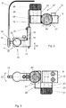
- Fig. 2 a holding device according to the invention for a fiber optic line of the optical sensor in a first sectional view
- Fig. 3 the holding device of the invention Fig. 2 in a second sectional view
- Fig. 4 an embodiment of a connecting rod for holding a holding part for the fiber optic line
- Fig. 5 a schematic representation of a reflection-increasing agent on the anvil of a human ear.
- Fig. 1 shows a view of the implantation area for the implantation of an optical sensor directed at the anvil in the human ear.
- the ear 1 comprises an eardrum 2, which separates the outer ear 3 from the middle ear 4.
- the auditory ossicles including the anvil 5 are arranged in the tympanic cavity of the middle ear 4.
- the optical sensor is arranged to measure the vibrations of the anvil 5 with the aid of a light beam emerging from the free end of a fiber optic line 6.
- the anvil 5 carries a reflector 7 to increase the light reflection.
- a collimator 8 is arranged at a distance from the reflector 7.
- the holder for the fiber-optic line 6 comprises a fastening plate 9 which is fastened to the skull bone.
- the bracket is in Fig. 1 shown only schematically, it being evident that the fastening plate 9, as shown in more detail in FIGS Figs. 2 and 3 is shown, carries a guide tube 10 into which the fiber optic line 6 is inserted.
- the sensor also includes an optoelectronic sound signal processor module 11, which is accommodated in a biocompatible, implantable shell.
- the module 11 is connected to the fiber optic line 6 and receives the light signal reflected by the reflector 7 and coupled into the free end of the fiber optic line 6. The light signal is evaluated in the module 11 in order to determine the vibrations of the anvil 5 or the reflector 7 attached to it.
- the module 11 is implanted in the skull and firmly attached to the bone.
- the fastening plate 9 is fastened to the skull bone with screws 12. Furthermore, an elongated connecting structure 13 extending away from the fastening plate 9 and connecting the guide tube 10 to the fastening plate 9 is provided in the form of a rod, on whose end region facing away from the fastening plate 9 a hinge device 14 is arranged.
- the joint device 14 comprises a ball joint which has a ball 15 which is rotatably held between clamping jaws 16 and 17.
- a connecting rod 18, which carries the guide tube 10, is rigidly attached to the ball 15.
- the clamping force with which the Ball 15 is clamped between the clamping jaws 16 and 17 can be adjusted by means of the adjusting screw 19.
- the ball joint 14 allows a three-axis adjustment of the orientation of the guide tube 10 when the adjusting screw 19 is loosened accordingly. After the desired alignment has been set, this is fixed by tightening the adjusting screw 19.
- a translational adjustment of the guide tube 10 in the direction of the double arrow 20 takes place in that the elongated connecting structure 13 has a sliding guide for the joint device 14 running in the direction of its longitudinal axis.
- the selected translational position is fixed by means of the locking screw 21.
- an actuator-driven, in particular motor-driven pivoting device 37 which enables the guide tube 10 to be adjusted in two orthogonal directions.
- the pivoting device comprises two gear wheels 22 and 23 which are connected to the corresponding counterparts by corresponding screws 24 and 25.
- the screws 24 and 25 can be operated by electric motors 26 and 27, respectively.
- the toothed wheel 23 can be firmly connected to the counterpart 28 of the toothed wheel 22 by welding, in particular laser welding.
- a rotation of the motor 27 in the direction of the double arrow 29 leads to a pivoting of the guide tube 10 according to the double arrow 30.
- a rotation of the motor 26 in the direction of the double arrow 31 leads to a pivoting of the guide tube 10 according to the double arrow 32.
- the motors 26 and 27 can remotely controlled via a wireless connection so that the Alignment of the guide tube 10 together with the fiber optic line received therein is possible even years after the implantation has taken place.
- a modified embodiment of the holder in which the connecting rod 18 between the ball 15 and the guide tube 10 has an S-shape.
- the S-shaped connecting rod 18 comprises a central section 34 which extends in the direction of the longitudinal axis of the elongated connecting structure 13 or in the direction of the longitudinal axis of the guide tube 10 and is arranged between two further sections 35 extending transversely to the central section 34.
- the connection 18 allows an adaptation to the individual distance of the oscillating measurement target from the pivoting device parallel to the guide tube 10.
- the sections 35 allow an adaptation of the distance from the ball in the narrow anterior angle between the tympanum (tegmen tympani) and the wall of the ear canal.
- the guide tube 10 has a conical bevel 33 which facilitates the insertion of the fiber-optic line 6.
- a reflector 7 is fastened to the anvil 5 to increase the reflection, the fastening being carried out, for example, with the aid of a band 36.
Landscapes
- Health & Medical Sciences (AREA)
- General Health & Medical Sciences (AREA)
- Otolaryngology (AREA)
- Neurosurgery (AREA)
- Physics & Mathematics (AREA)
- Engineering & Computer Science (AREA)
- Acoustics & Sound (AREA)
- Signal Processing (AREA)
- Prostheses (AREA)
Priority Applications (2)
| Application Number | Priority Date | Filing Date | Title |
|---|---|---|---|
| EP20020081.4A EP3869824A1 (fr) | 2020-02-21 | 2020-02-21 | Dispositif de maintien pour un fil de fibre optique d'une appareil auditif pouvant être implanté |
| PCT/IB2021/051378 WO2021165872A1 (fr) | 2020-02-21 | 2021-02-18 | Dispositif de maintien pour un câble à fibres optiques d'une prothèse auditive implantable |
Applications Claiming Priority (1)
| Application Number | Priority Date | Filing Date | Title |
|---|---|---|---|
| EP20020081.4A EP3869824A1 (fr) | 2020-02-21 | 2020-02-21 | Dispositif de maintien pour un fil de fibre optique d'une appareil auditif pouvant être implanté |
Publications (1)
| Publication Number | Publication Date |
|---|---|
| EP3869824A1 true EP3869824A1 (fr) | 2021-08-25 |
Family
ID=69726409
Family Applications (1)
| Application Number | Title | Priority Date | Filing Date |
|---|---|---|---|
| EP20020081.4A Withdrawn EP3869824A1 (fr) | 2020-02-21 | 2020-02-21 | Dispositif de maintien pour un fil de fibre optique d'une appareil auditif pouvant être implanté |
Country Status (2)
| Country | Link |
|---|---|
| EP (1) | EP3869824A1 (fr) |
| WO (1) | WO2021165872A1 (fr) |
Citations (4)
| Publication number | Priority date | Publication date | Assignee | Title |
|---|---|---|---|---|
| WO2000025550A2 (fr) * | 1998-10-23 | 2000-05-04 | Aleksandar Vujanic | Recepteur de sons implantable destine a des protheses auditives |
| DE19915684A1 (de) * | 1999-04-07 | 2000-11-02 | Implex Hear Tech Ag | Implantierbares Positionier- und Fixiersystem für aktorische und sensorische Implantate |
| DE102009035386A1 (de) * | 2009-07-30 | 2011-02-03 | Cochlear Ltd., Lane Cove | Hörhilfeimplantat |
| DE102009051771A1 (de) * | 2009-10-29 | 2011-05-05 | Moldenhauer, Martin, Dipl.-Ing. | Voll implantierbares optisches Mikrofon |
-
2020
- 2020-02-21 EP EP20020081.4A patent/EP3869824A1/fr not_active Withdrawn
-
2021
- 2021-02-18 WO PCT/IB2021/051378 patent/WO2021165872A1/fr active Application Filing
Patent Citations (5)
| Publication number | Priority date | Publication date | Assignee | Title |
|---|---|---|---|---|
| WO2000025550A2 (fr) * | 1998-10-23 | 2000-05-04 | Aleksandar Vujanic | Recepteur de sons implantable destine a des protheses auditives |
| EP1123635B1 (fr) | 1998-10-23 | 2002-03-27 | Aleksandar Vujanic | Recepteur de sons implantable destine a des protheses auditives |
| DE19915684A1 (de) * | 1999-04-07 | 2000-11-02 | Implex Hear Tech Ag | Implantierbares Positionier- und Fixiersystem für aktorische und sensorische Implantate |
| DE102009035386A1 (de) * | 2009-07-30 | 2011-02-03 | Cochlear Ltd., Lane Cove | Hörhilfeimplantat |
| DE102009051771A1 (de) * | 2009-10-29 | 2011-05-05 | Moldenhauer, Martin, Dipl.-Ing. | Voll implantierbares optisches Mikrofon |
Non-Patent Citations (6)
| Title |
|---|
| A. DANDRIDGEA.B. TVETENT.G. GIALLORENZI: "Homodyne Demodulation Scheme for Fiber Optic Sensors Using Phase Generated Carrier", IEEE J.QUANTUM ELEC., vol. QE-18, no. 10, 1982, pages 1647 - 1653 |
| G.SCHMITTW. WENZELK. DOLDE: "Integrated optical 3x3-coupler on LiNb03: comparison between theory and experiment", PROC.SPIE, VOL.1141 5TH EUROPEAN CONFERENCE ON INTEGRATED OPTICS: ECIO 89, vol. 1141, 1989, pages 67 - 71 |
| J.H. COLEB.A. DANVERJ.A. BUCARO: "Syntetic-Heterodyne Interferometric Demodulation", IEEE J.QUANTUM ELEC., vol. QE-18, no. 4, 1982, pages 694 - 697 |
| K.P. KOOA.B. TVETENA. DANDRIDGE: "Passive stabilization scheme for fiber interferometers using (3x3) fiber directinal couplers", APPL.PHYS.LETT., vol. 41, no. 7, 1982, pages 616 - 618, XP000916294, DOI: 10.1063/1.93626 |
| L. CHANGCHUNL. FEI: "Passive Interfermetric Optical Fiber Sensor Using 3x3 Directional Coupler", PROC.SPIE, vol. 2895, 1995, pages 565 - 571 |
| R. FUESTN. FABRICIUSU. HOLLENBACHB. WOLF: "Interferometric displacement sensor realized with a planar 3x3 directional coupler in glass", PROC.SPIE, VOL.1794 INTEGRATED OPTICAL CIRCUITS II, vol. 1794, 1992, pages 352 - 365, XP000578457, DOI: 10.1117/12.141900 |
Also Published As
| Publication number | Publication date |
|---|---|
| WO2021165872A1 (fr) | 2021-08-26 |
Similar Documents
| Publication | Publication Date | Title |
|---|---|---|
| AT408607B (de) | Implantierbarer schallrezeptor für hörhilfen | |
| DE102009035386B4 (de) | Hörhilfeimplantat | |
| US6381490B1 (en) | Optical scanning and imaging system and method | |
| EP1181950B1 (fr) | Système auditif implantable comportant des moyens de mesure de la qualité d'accouplement | |
| EP1041857B1 (fr) | Système auditif implantable avec audiomètre | |
| DE19618964C2 (de) | Implantierbares Positionier- und Fixiersystem für aktorische und sensorische Implantate | |
| EP1105765B1 (fr) | Systeme de balayage optique et de formation d'image | |
| US6390970B1 (en) | Implantable positioning and fixing system for actuator and sensor implants | |
| US20070161848A1 (en) | Implantable interferometer microphone | |
| DE112008002383T5 (de) | Präzises targeting chirurgischer Photodisruption | |
| DE19618945A1 (de) | Vorrichtung zur Positionierung und Fixierung von chirurgischen, therapeutischen oder diagnostischen Instrumenten | |
| EP1041856A2 (fr) | Système auditif totalement implantable avec capteur télémetrique | |
| DE19948375A1 (de) | Anordnung zum mechanischen Ankoppeln eines Treibers an eine Ankoppelstelle der Ossikelkette | |
| DE102015106560B4 (de) | Hörprothese | |
| EP3869824A1 (fr) | Dispositif de maintien pour un fil de fibre optique d'une appareil auditif pouvant être implanté | |
| EP1209946A2 (fr) | Dispositif et procédé pour démonstration préopératoire des prothèses auditives implantables | |
| DE19801959A1 (de) | Optischer Aufbau zur berührungslosen Schwingungsmessung | |
| DE10237620A1 (de) | Übertragungsvorrichtung zur Einleitung von Licht in das Ohr | |
| DE10014200C2 (de) | Gerät zum elektromechanischen Stimulieren und Prüfen des Gehörs | |
| DE102009051771A1 (de) | Voll implantierbares optisches Mikrofon | |
| DE102004056522A1 (de) | System zur intraoperativen Qualitätssicherung bei implantierbaren Hörgeräten |
Legal Events
| Date | Code | Title | Description |
|---|---|---|---|
| PUAI | Public reference made under article 153(3) epc to a published international application that has entered the european phase |
Free format text: ORIGINAL CODE: 0009012 |
|
| STAA | Information on the status of an ep patent application or granted ep patent |
Free format text: STATUS: THE APPLICATION HAS BEEN PUBLISHED |
|
| AK | Designated contracting states |
Kind code of ref document: A1 Designated state(s): AL AT BE BG CH CY CZ DE DK EE ES FI FR GB GR HR HU IE IS IT LI LT LU LV MC MK MT NL NO PL PT RO RS SE SI SK SM TR |
|
| STAA | Information on the status of an ep patent application or granted ep patent |
Free format text: STATUS: THE APPLICATION IS DEEMED TO BE WITHDRAWN |
|
| 18D | Application deemed to be withdrawn |
Effective date: 20220226 |