EP1123635B1 - Recepteur de sons implantable destine a des protheses auditives - Google Patents
Recepteur de sons implantable destine a des protheses auditives Download PDFInfo
- Publication number
- EP1123635B1 EP1123635B1 EP99953416A EP99953416A EP1123635B1 EP 1123635 B1 EP1123635 B1 EP 1123635B1 EP 99953416 A EP99953416 A EP 99953416A EP 99953416 A EP99953416 A EP 99953416A EP 1123635 B1 EP1123635 B1 EP 1123635B1
- Authority
- EP
- European Patent Office
- Prior art keywords
- optical sensor
- evaluation circuit
- vibration
- sound
- distance
- Prior art date
- Legal status (The legal status is an assumption and is not a legal conclusion. Google has not performed a legal analysis and makes no representation as to the accuracy of the status listed.)
- Expired - Lifetime
Links
Images


Classifications
-
- H—ELECTRICITY
- H04—ELECTRIC COMMUNICATION TECHNIQUE
- H04R—LOUDSPEAKERS, MICROPHONES, GRAMOPHONE PICK-UPS OR LIKE ACOUSTIC ELECTROMECHANICAL TRANSDUCERS; DEAF-AID SETS; PUBLIC ADDRESS SYSTEMS
- H04R25/00—Deaf-aid sets, i.e. electro-acoustic or electro-mechanical hearing aids; Electric tinnitus maskers providing an auditory perception
- H04R25/60—Mounting or interconnection of hearing aid parts, e.g. inside tips, housings or to ossicles
- H04R25/604—Mounting or interconnection of hearing aid parts, e.g. inside tips, housings or to ossicles of acoustic or vibrational transducers
- H04R25/606—Mounting or interconnection of hearing aid parts, e.g. inside tips, housings or to ossicles of acoustic or vibrational transducers acting directly on the eardrum, the ossicles or the skull, e.g. mastoid, tooth, maxillary or mandibular bone, or mechanically stimulating the cochlea, e.g. at the oval window
-
- H—ELECTRICITY
- H04—ELECTRIC COMMUNICATION TECHNIQUE
- H04R—LOUDSPEAKERS, MICROPHONES, GRAMOPHONE PICK-UPS OR LIKE ACOUSTIC ELECTROMECHANICAL TRANSDUCERS; DEAF-AID SETS; PUBLIC ADDRESS SYSTEMS
- H04R2225/00—Details of deaf aids covered by H04R25/00, not provided for in any of its subgroups
- H04R2225/67—Implantable hearing aids or parts thereof not covered by H04R25/606
Definitions
- the invention relates to an implantable sound receptor for hearing aids, in particular for implantable hearing aids.
- a hearing aid of this type Used transducers with which sound waves in electrical Signals can be converted.
- Such converters are in Form of microphones known and need a corresponding Membrane, the vibration of which is converted into electrical signals can be.
- Sound vibrations can be sensitive to pressure Membranes are included, as is the case with the construction is common from microphones, or detected by vibrometers with what vibrations as acceleration signals or but as strain gauges when vibrating Components are included.
- accelerometers are in the form of piezoresistive Vibration sensors proposed.
- Alternatives are capacitive acceleration sensors for scanning sound vibrations known.
- Such miniaturized sensors were already proposed for implantation in the middle ear area, where acoustic pressure waves, which in the range of Middle ear arise in the form of mechanical vibrations be scanned.
- Such microphone constructions are in principle but relatively insensitive because of an exact match the acoustic impedance between the sensor and the tympanic cavity of the Middle ear can not be easily achieved.
- sounds that are heard are generated by sound waves caused, the pitch with increasing frequency and the volume increases with increasing amplitude.
- sounds and sounds that represent sound mixtures also create one Variety of different tones that do not sound together regularly Frequency and height, which is perceived as noise become.
- the sound waves perceived by the auricle to the outer ear canal are guided and the eardrum vibrates. With the drumstick has grown together, the other Transmission over the ossicles through the stirrup plate to the perilymphatic fluid that the Cortical organ vibrated.
- the hair cells in the cortic organ generate nerve impulses that the auditory nerve leads to the brain, where it is consciously perceived become.
- the eardrum acts as a pressure receiver and points about 1 cm in diameter. If for the inclusion of Sound wave microphones with such large membranes are used Such microphones are hardly suitable for one Implantation, since the space required for this in the area of the Ear is not available.
- miniaturization of microphones leads to decrease sensitivity, doing so not least due to the lack of matching of the acoustic impedance between the microphone and the ambient air. Even if this effect is caused by implanting the microphone under the skin can be improved, this leads to a change of the scannable frequency range, in particular higher Frequencies are attenuated more.
- Other mechanical too Sound wave receptors such as those filled with fluid Tubes lead to the viscosity of the used Fluid damping to be returned, with rigid acoustic couplers are generally unsuitable for an implantation.
- WO 79/00841 describes the basics of an interferometric Measuring principles for the detection of oscillatory movements can be seen with which a series of vibration properties detected by membranes and in particular an eardrum can be.
- a measuring device is stationary, outside the body and away from vibrating surfaces built up. So far, only fully implantable Hearing aids in which the implant is miniaturized Microphone capsule contains.
- Such training is for example EP 831 674 A2.
- the invention now aims to be a small-scale implantable To create sound receptor, which has the disadvantages the known sound receptors can be avoided and the acoustic Sensitivity over all essential for hearing Frequency range from about 100 Hz to over 10 kHz can be maintained at a consistently high level.
- the invention further aims to keep the dimensions so small that the Implantation in the middle ear and / or in the neighboring mastoid cavity is possible.
- the surgical intervention should be preferred be reversible, if the sound receptor fails no significant deterioration in pre-existing hearing should occur. Limiting can, however, depend on an operative of the actuator used and its point of attack Interruption of the formwork cable chain to avoid feedback to be required. In addition to these requirements for one implantable sound receptor should naturally also the energy consumption of the sound receptor and a subsequent evaluation circuit be kept so low that miniaturization allows a total implantation.
- the implantable device is used to achieve this object Sound receptor for implantable hearing aids essentially in that the sound sensor as an optical sensor for Vibration or distance measurements is formed and in Distance from the surface of an excitable to acoustic vibrations Part of the sound transmission is arranged in the ear that the optical sensor at a distance from the scanned part is arranged, which is larger than the maximum occurring Displacement of the scanned part towards the end face of the sensor and / or in a collision preventing Distance is kept adjustable that the optical sensor with an electronic evaluation circuit is connected that the Evaluation circuit signals for electromechanical vibration generators and / or for the stimulation of the cortic organ and / or of the auditory nerve and / or brain stem and Has connections for corresponding signal lines and that the evaluation circuit with a stabilizer circuit Compensation for the shift in the operating point of the interferometer by low-frequency shifts of the sampled Part interacts.
- the optical sensor is at a distance from the surface of a part of the Vibration transmission is arranged or can be arranged in the ear, it is ensured that damping of the vibration of such parts of the vibration transmission that can be excited by vibrations can be safely excluded and use of optical sensors allows the use extremely small sensors.
- Optical sensors are to be understood here as sensors which do not necessarily use visible light.
- electromagnetic waves can be used in a relatively wide frequency range, which goes beyond the spectrum of visible light.
- laser diodes can be used as transmitters in the infrared and ultraviolet range of the radiation as well as in the visible range, as long as the vibrating surface to be measured is sufficiently reflective in the range of the irradiated wavelength.
- Optical sensors are primarily used to measure the optical parameters of the reflected components of the emitted signal, with the procedure for evaluating the signals of the sound receptor being such that the optical sensor is used with an interferometer to evaluate the amplitude, frequency and / or the relative phase position of the vibration of the scanned part is connected.
- the use of the interferometer principle allows the non-contact detection of even small amplitudes of natural vibrations in the area of the ossicles.
- the range to be recorded here ranges from amplitudes of 10 -11 m to about 10 -5 m, amplitudes higher than about 5x10 -5 m, as can be observed with sound radiation of about 120 dB, generally not for further measurements come into consideration, since they are already likely to damage the inner ear.
- the vibration of the ossicles and the eardrum is also superimposed in the ear on a low-frequency, quasi-static or slow displacement of the eardrum membrane and the ossicles, which are due to differences in air pressure or pressure in the inner ear .
- Such low-frequency shifts are caused, for example, by changing the air pressure when driving in elevators, cable cars or airplanes, with significant low-frequency fluctuations being observed by the sudden opening of the Eustachian tube even when blowing.
- Such low-frequency shifts can be at least 10 2 higher in amplitude than the maximum amplitudes occurring in the physiological sonication.
- Optical sensors must now be arranged so that even with such displacements there is no contact with the part to be scanned and the design according to the invention is therefore such that the optical sensor is arranged at a distance from the scanned part which is greater than that maximum occurring displacement of the scanned part in the direction of the sensor and / or in a collision-preventing distance is kept adjustable.
- the use of an adjustable holder to maintain a defined distance can comprise a servo motor, the control signals of the control motor being used for the determination of the acoustic vibrations, and the control movements themselves being triggered by the optical sensor.
- Optical scanning is particularly easy in that the optical sensor with at least one light or laser diode cooperates and the reflected signals over At least fibers of waveguides, in particular optical fibers an optoelectronic coupling component, for example one Photodiode, an electronic evaluation circuit supplied are.
- the one in the middle ear or the epitympanon or attic room too implanting part of the sensor is limited to such Training on the relatively small free end of the optical fiber, via which the optical signals are fed and the reflected signals are taken.
- one or more optical systems such as Lenses, beam splitters, prisms, mirrors or the like are arranged in order to specify or localize the measurement accordingly.
- the evaluation circuit must subsequently be appropriately amplified Provide a signal for the stimulus of the auditory nerve, with training here being advantageously made such that the evaluation circuit signals for electromechanical vibrators and / or for the electrical stimulation of the Cortic organ and / or the auditory nerve and / or the brain stem generated and has connections for corresponding signal lines.
- implantable end of the optical sensor due to turbidity incorrect measurements or is subject to fluctuations in sensitivity taken advantage of the training so that the free ends of the optical sensor with a coating that inhibits cell growth are provided.
- the procedure can advantageously be such that the Evaluation circuit at least two signals for determining the Phase position are supplied, the determination of the phase position in a known manner depending on the type of interferometer used and a corresponding circuit arrangement of the evaluation circuit enables active or passive stabilization. ever by arrangement applies to the optimal sensitivity of the optical Sensor by a defined distance to the measured Surface of the specified working point. Low frequency shifts the parts to be scanned can of course do this cause this optimal working point is left or even a phase shift or phase reversal occurs.
- the evaluation circuit is a stabilizer circuit to compensate for the shift in the operating point of the interferometer due to low frequency shifts of the contains the scanned part.
- a sensor for determining the distance of the part to be scanned is provided by the optical sensor.
- the Stabilization of interferometric signals can be done by comparison with a reference signal or by measuring a plurality of Signals take place in a particularly simple manner, wherein in the Beam path polarizing beam splitter can be switched on can and the signals independently and from each other Photodiodes can be detected.
- Conclusions on the correct phase position can also be calculated from a mathematical Derive analysis of the measurement waveform, using frequency comparisons for this purpose and especially the evaluation of vibrations higher order can be used in the stabilizer circuit can.
- the training is for the exact positioning of the sound receptor taken in a particularly simple manner so that the free End of the optical sensor in an adjustable bearing block and / or is connected to an adjustment drive, whereby exact orientation and exact positioning relative to Surface of the part can be ensured, the Vibration should be measured.
- Interferometers can be of any design, such as as a Michelson, Fabry-Perot or Fizeau interferometer be formed using suitable stabilization algorithms for example in the article by K.P. Koo, A.B. Tveten, A. Dandridge, "Passive stabilization scheme for fiber interferometers using (3x3) fiber directinal couplers ", in Appl.Phys.Lett., Vol. 41, No.7, pp. 616-618, 1982, G. Schmitt, W. Wenzel, K.
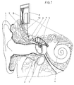
- Fig. 1 the ear of an ear is designated 1. Sound vibrations subsequently reach the one designated as 2 Membrane, namely the eardrum, with which the ossicles interact. The ossicles become common here designated with the reference number 3.
- the ossicles are located in the middle ear.
- the cochlea is labeled 4.
- the non-contact sensor for sensing vibrations from Ear bone 3 is implanted and protrudes in the mastoid cavity with its tip in the attic room or over the drilled Chorda-facial angle in the middle ear. He has a free one End 5, which is in a stable sleeve (casing), which is held orientably in a bearing block 6.
- the bearing block 6 can here in the mastoid cavity or the surrounding Skull bones must be fixed, with the free end of the optical sensor essentially from the free end of a Optical fiber or waveguide 7 exists.
- the tip contains advantageously an optical system, for example lenses, Beam guides, prisms, mirrors or the like, or a bend in the Fiber tip for deflecting the optical beam path around the Allow registration from the optimal direction.
- the Optical waveguide 7 is connected to an optoelectronic evaluation circuit 8 connected, in which an interferometer 9 is arranged is.
- the optoelectronic evaluation circuit 8 can Housing also an energy supply in the form of a battery included, the circuit arrangement corresponding input-output circuits contains, for signal processing, noise suppression, acoustic limitation etc. corresponding to a Includes hearing aid electronics or these required for the actuator Circuits in a separate implantable part, the is coupled with an electrical cable, are housed.
- the electrical signals via the lines 10 to Cochlea 4 can be transmitted.
- this optoelectronic evaluation circuit 8 can this optoelectronic evaluation circuit as a whole be implanted.
- the Actuator can be one, the ossicle or the perilymph directly set in acoustic vibrations or a cochlear implant, that electrically irritates the auditory nerve or a brainstem implant, that directly irritates the brain stem.
- FIG. 2 A block diagram of the circuit arrangement selected in this context can be seen in Fig. 2.
- the skin that The implant covering is schematically indicated by 11, wherein subcutaneously in the area of the middle ear, the mastoid cavity or on the evaluation circuit and, if necessary, the Energy supply is housed.
- the battery is here schematically with 12, the optical sensor and the interferometer at 13, the evaluation electronics at 14 and the actuating component, via which the signals after processing in the hearing aid electronics to an electromechanical amplifier Perilymph vibrations or to a cochlear implant or a Brain stem implant (labeled 15).
- the energy supply by the battery 12 can preferably by a Rechargeable battery are made, for which additional inputs are provided for an induction coil 17, via which with an external charging or control unit 18 for recharging the battery and, if necessary, programming the electronics is made possible.
- the transfer can be contactless via a couplable to the subcutaneous induction coil 17 Induction coil 19 of the control and charging unit 18 made become.
- FIG. 3 is schematically one possible Training of the bearing block 6 explained in more detail.
- a base plate 20 is fixed, on which a displaceable Carriage 21 is mounted.
- the sliding carriage 21 carries a ball pin 22 on which a clamp with jaws 23 and 24 fixed by means of a clamping screw 25 orientable is.
- the jaws 23 and 24 have spherical bearing surfaces on which on the circumference of the ball 26 of the ball pin 22 is pivotable are orientable, so that an exact adjustment in different Spatial coordinates is enabled.
- an optical fiber 27 in brought defined position, the free end 28 so oriented is that it is the reflected radiation from a vibrating Can take part of the inner ear.
- the free end 28 of the optical fiber 27 can be optical systems, prisms, mirrors or the like. For deflecting the beam path if so desired.
- the signals arrive via the Optical waveguide 27 for optoelectronic evaluation circuit, which contains the interferometer.
- the arrangement of such, for adjusting the free end 28 of a component suitable for an optical waveguide, can be relative large mastoid cavity easily done.
- the fine adjustment serves to achieve the desired distance and desired orientation to the surface of the vibrating to be measured Part of the middle ear.
- the optical complexity can also be increased. It can also, for example, from the mastoid cavity directly into the Attic can be measured and the scanning, for example on Anvil head. Due to the type of vibration transmission However, it must be taken into account here that the individual Ossicles related to the vibration of the eardrum partially swing with opposite phase. Scanning at locations with less quasi-static Shift has the advantage of being the extent of a linear shift due to pressure differences compared to the measuring distance becomes much less, so that the effort for stabilization the phase position and for eliminating the "fading" effect can be reduced.
Landscapes
- Health & Medical Sciences (AREA)
- General Health & Medical Sciences (AREA)
- Otolaryngology (AREA)
- Neurosurgery (AREA)
- Physics & Mathematics (AREA)
- Engineering & Computer Science (AREA)
- Acoustics & Sound (AREA)
- Signal Processing (AREA)
- Prostheses (AREA)
- Measurement Of Mechanical Vibrations Or Ultrasonic Waves (AREA)
- Electrostatic, Electromagnetic, Magneto- Strictive, And Variable-Resistance Transducers (AREA)
- Materials For Medical Uses (AREA)
Claims (6)
- Récepteur acoustique implantable pour aides auditives, caractérisé en ce que le capteur acoustique est réalisé en tant que capteur optique pour des mesures de vibrations ou de distance et est disposé dans l'oreille, à distance de la surface d'une partie de la transmission des sons qui peut être mise en oscillations acoustiques, en ce que le capteur optique est disposé à une distance de la partie détectée qui est plus grande que le déplacement maximal de la partie détectée en direction de la surface frontale du capteur et/ou est maintenu, de manière ajustable, à une distance empêchant une collision, en ce que le capteur optique est relié à un circuit d'exploitation électronique, en ce que le circuit d'exploitation (8) génère des signaux pour des générateurs électromécaniques d'oscillations et/ou pour la stimulation de l'organe de Corti et/ou du nerf auditif et/ou du cerveau et comporte des connexions pour des lignes de signal (10) correspondantes et en ce que le circuit d'exploitation (8) coopère avec un circuit de stabilisation pour la compensation du déplacement du point de travail de l'interféromètre (9) par des déplacements à basse fréquence de la partie détectée.
- Récepteur acoustique implantable selon la revendication 1, caractérisé en ce que le capteur optique coopère avec au moins une diode luminescente ou diode laser et les signaux réfléchis sont acheminés, par des fibres de guide d'ondes, en particulier de guide d'ondes optiques (7), au moins vers un composant de couplage optoélectronique, par exemple une photodiode, du circuit électronique d'exploitation.
- Récepteur acoustique implantable selon la revendication 1 ou 2, caractérisé en ce que le capteur optique est relié à un interféromètre (9) pour l'exploitation de l'amplitude, de la fréquence et/ou de la position de phase relative de l'oscillation de la partie détectée.
- Récepteur acoustique implantable selon l'une des revendications 1 à 3, caractérisé en ce que vers le circuit d'exploitation (8) sont acheminés au moins deux signaux pour déterminer les paramètres d'oscillation de la partie détectée.
- Récepteur acoustique implantable selon l'une des revendications 1 à 4, caractérisé en ce que les extrémités libres (5) du capteur optique sont pourvues d'un revêtement empêchant la croissance de cellules.
- Récepteur acoustique implantable selon l'une des revendications 1 à 5, caractérisé en ce que l'extrémité libre (5) du capteur optique est fixée, de manière ajustable, dans un support (6) et/ou est reliée à un mécanisme d'ajustement.
Applications Claiming Priority (3)
| Application Number | Priority Date | Filing Date | Title |
|---|---|---|---|
| AT178798 | 1998-10-23 | ||
| AT0178798A AT408607B (de) | 1998-10-23 | 1998-10-23 | Implantierbarer schallrezeptor für hörhilfen |
| PCT/AT1999/000253 WO2000025550A2 (fr) | 1998-10-23 | 1999-10-20 | Recepteur de sons implantable destine a des protheses auditives |
Publications (2)
| Publication Number | Publication Date |
|---|---|
| EP1123635A2 EP1123635A2 (fr) | 2001-08-16 |
| EP1123635B1 true EP1123635B1 (fr) | 2002-03-27 |
Family
ID=3520974
Family Applications (1)
| Application Number | Title | Priority Date | Filing Date |
|---|---|---|---|
| EP99953416A Expired - Lifetime EP1123635B1 (fr) | 1998-10-23 | 1999-10-20 | Recepteur de sons implantable destine a des protheses auditives |
Country Status (8)
| Country | Link |
|---|---|
| US (1) | US6491644B1 (fr) |
| EP (1) | EP1123635B1 (fr) |
| AT (2) | AT408607B (fr) |
| AU (1) | AU755935B2 (fr) |
| DE (1) | DE59901093D1 (fr) |
| DK (1) | DK1123635T3 (fr) |
| ES (1) | ES2174644T3 (fr) |
| WO (1) | WO2000025550A2 (fr) |
Cited By (1)
| Publication number | Priority date | Publication date | Assignee | Title |
|---|---|---|---|---|
| EP3869824A1 (fr) | 2020-02-21 | 2021-08-25 | Zoran Djinovic | Dispositif de maintien pour un fil de fibre optique d'une appareil auditif pouvant être implanté |
Families Citing this family (42)
| Publication number | Priority date | Publication date | Assignee | Title |
|---|---|---|---|---|
| US7697980B1 (en) * | 2002-04-03 | 2010-04-13 | Purdue Research Foundation | Technique for high spatial resolution, focused electrical stimulation of electrically-excitable tissue |
| WO2004018980A2 (fr) * | 2002-08-20 | 2004-03-04 | The Regents Of The University Of California | Detecteurs de vibrations, detecteurs sonores, aides auditives, implants cochleaires et procedes connexes |
| US7668325B2 (en) | 2005-05-03 | 2010-02-23 | Earlens Corporation | Hearing system having an open chamber for housing components and reducing the occlusion effect |
| US8652040B2 (en) | 2006-12-19 | 2014-02-18 | Valencell, Inc. | Telemetric apparatus for health and environmental monitoring |
| EP2208367B1 (fr) | 2007-10-12 | 2017-09-27 | Earlens Corporation | Système et procédé multifonction pour une audition et une communication intégrées avec gestion de l'annulation du bruit et de la contre-réaction |
| DE102007054325A1 (de) * | 2007-11-14 | 2009-05-28 | Siemens Medical Instruments Pte. Ltd. | Hörhilfegerät |
| CN102124757B (zh) | 2008-06-17 | 2014-08-27 | 依耳乐恩斯公司 | 传输音频信号及利用其刺激目标的系统、装置和方法 |
| EP2303204A4 (fr) | 2008-06-25 | 2014-06-25 | Cochlear Ltd | Système de microphone implantable à performances améliorées |
| DE102008034715A1 (de) | 2008-07-25 | 2010-02-04 | Siemens Medical Instruments Pte. Ltd. | Hörhilfe mit UV-Sensor und Betriebsverfahren |
| DK2342905T3 (en) | 2008-09-22 | 2019-04-08 | Earlens Corp | BALANCED Luminaire Fittings and Methods of Hearing |
| WO2010068984A1 (fr) * | 2008-12-16 | 2010-06-24 | Cochlear Limited | Microphone implantable |
| CN102598712A (zh) | 2009-06-05 | 2012-07-18 | 音束有限责任公司 | 光耦合的中耳植入体声学系统和方法 |
| US9544700B2 (en) | 2009-06-15 | 2017-01-10 | Earlens Corporation | Optically coupled active ossicular replacement prosthesis |
| EP2443843A4 (fr) | 2009-06-18 | 2013-12-04 | SoundBeam LLC | Dispositifs implantables dans la membrane du tympan pour systèmes et procédés d'aide auditive |
| KR101833073B1 (ko) | 2009-06-18 | 2018-02-27 | 이어렌즈 코포레이션 | 광학적으로 결합된 달팽이관 임플란트 시스템 및 방법 |
| WO2011005479A2 (fr) | 2009-06-22 | 2011-01-13 | SoundBeam LLC | Systèmes et procédés de conduction osseuse à couplage optique |
| BRPI1016075A2 (pt) | 2009-06-22 | 2016-05-10 | SoundBeam LLC | dispositivo para transmitir som para um ouvido de um usuário e métodos associados. |
| WO2010151647A2 (fr) | 2009-06-24 | 2010-12-29 | SoundBeam LLC | Systèmes et procédés d'actionnement cochléaire à couplage optique |
| US8845705B2 (en) | 2009-06-24 | 2014-09-30 | Earlens Corporation | Optical cochlear stimulation devices and methods |
| DE102009035386B4 (de) * | 2009-07-30 | 2011-12-15 | Cochlear Ltd. | Hörhilfeimplantat |
| DE102009051771A1 (de) | 2009-10-29 | 2011-05-05 | Moldenhauer, Martin, Dipl.-Ing. | Voll implantierbares optisches Mikrofon |
| EP2506923A1 (fr) * | 2009-12-04 | 2012-10-10 | Advanced Bionics AG | Systèmes et procédés pour poser un système d'implant cochléaire sur un patient sur la base du déplacement du muscle de l'étrier |
| DE102010041529A1 (de) | 2010-09-28 | 2011-09-08 | Siemens Medical Instruments Pte. Ltd. | Hörhilfeapparat mit integriertem Otoskop |
| WO2012088187A2 (fr) | 2010-12-20 | 2012-06-28 | SoundBeam LLC | Appareil auditif intra-auriculaire anatomiquement personnalisé |
| US20130066228A1 (en) * | 2011-09-13 | 2013-03-14 | Edmond Capcelea | Minimizing mechanical trauma due to implantation of a medical device |
| US9544675B2 (en) | 2014-02-21 | 2017-01-10 | Earlens Corporation | Contact hearing system with wearable communication apparatus |
| US10034103B2 (en) | 2014-03-18 | 2018-07-24 | Earlens Corporation | High fidelity and reduced feedback contact hearing apparatus and methods |
| DK3169396T3 (da) | 2014-07-14 | 2021-06-28 | Earlens Corp | Glidende forspænding og peak-begrænsning for optiske høreapparater |
| US9924276B2 (en) | 2014-11-26 | 2018-03-20 | Earlens Corporation | Adjustable venting for hearing instruments |
| EP3888564A1 (fr) | 2015-10-02 | 2021-10-06 | Earlens Corporation | Appareil intra-auriculaire personnalisé d'administration de médicament |
| US10178483B2 (en) | 2015-12-30 | 2019-01-08 | Earlens Corporation | Light based hearing systems, apparatus, and methods |
| US11350226B2 (en) | 2015-12-30 | 2022-05-31 | Earlens Corporation | Charging protocol for rechargeable hearing systems |
| US10492010B2 (en) | 2015-12-30 | 2019-11-26 | Earlens Corporations | Damping in contact hearing systems |
| US20180048970A1 (en) | 2016-08-15 | 2018-02-15 | Earlens Corporation | Hearing aid connector |
| EP3510796A4 (fr) | 2016-09-09 | 2020-04-29 | Earlens Corporation | Systèmes, appareil et procédés auditifs de contact |
| WO2018093733A1 (fr) | 2016-11-15 | 2018-05-24 | Earlens Corporation | Procédure d'impression améliorée |
| WO2019173470A1 (fr) | 2018-03-07 | 2019-09-12 | Earlens Corporation | Dispositif auditif de contact et matériaux de structure de rétention |
| WO2019199680A1 (fr) | 2018-04-09 | 2019-10-17 | Earlens Corporation | Filtre dynamique |
| EP3831092A4 (fr) | 2018-07-31 | 2022-06-22 | Earlens Corporation | Démodulation dans un système auditif de contact |
| US10798498B2 (en) | 2018-10-30 | 2020-10-06 | Earlens Corporation | Rate matching algorithm and independent device synchronization |
| US10937433B2 (en) | 2018-10-30 | 2021-03-02 | Earlens Corporation | Missing data packet compensation |
| EP3949445A4 (fr) | 2019-03-27 | 2022-12-28 | Earlens Corporation | Châssis d'impression directe et plate-forme de système auditif à contact |
Family Cites Families (12)
| Publication number | Priority date | Publication date | Assignee | Title |
|---|---|---|---|---|
| GB2047894B (en) | 1978-03-09 | 1982-11-03 | Nat Res Dev | Speckle interferometric measurement of small oscillatory movements |
| DE3205686A1 (de) * | 1982-02-17 | 1983-08-25 | Robert Bosch Gmbh, 7000 Stuttgart | Hoergeraet |
| US4834111A (en) * | 1987-01-12 | 1989-05-30 | The Trustees Of Columbia University In The City Of New York | Heterodyne interferometer |
| JPH02275909A (ja) | 1989-04-18 | 1990-11-09 | Fujikura Ltd | 定偏波光ファイバ融着接続装置のファイバクランプ |
| EP0517323B1 (fr) * | 1991-06-07 | 1995-09-06 | Koninklijke Philips Electronics N.V. | Appareil de correction auditive intra-auriculaire |
| US5531787A (en) | 1993-01-25 | 1996-07-02 | Lesinski; S. George | Implantable auditory system with micromachined microsensor and microactuator |
| DE19527108A1 (de) * | 1995-07-25 | 1997-01-30 | Hans Peter Prof Dr Med Zenner | Ermittlung von Daten über das Hörvermögen |
| WO1997032385A1 (fr) * | 1996-03-01 | 1997-09-04 | Njc Innovations | Systeme de charge et/ou de transmission de signaux comportant une source lumineuse collaborant avec des cellules photovoltaiques |
| DE19638159C2 (de) | 1996-09-18 | 2000-09-07 | Implex Hear Tech Ag | Vollständig implantierbare Hörhilfe zur elektrischen Anregung des Gehörs |
| US5814095A (en) * | 1996-09-18 | 1998-09-29 | Implex Gmbh Spezialhorgerate | Implantable microphone and implantable hearing aids utilizing same |
| WO1998023205A1 (fr) * | 1996-11-25 | 1998-06-04 | Mdi Instruments, Inc. | Appareil et procede de diagnostic de l'oreille interne |
| US5897494A (en) * | 1997-01-31 | 1999-04-27 | The Board Of Trustees Of The University Of Arkansas | Vibrometer |
-
1998
- 1998-10-23 AT AT0178798A patent/AT408607B/de not_active IP Right Cessation
-
1999
- 1999-10-20 EP EP99953416A patent/EP1123635B1/fr not_active Expired - Lifetime
- 1999-10-20 AT AT99953416T patent/ATE215294T1/de active
- 1999-10-20 AU AU10177/00A patent/AU755935B2/en not_active Ceased
- 1999-10-20 ES ES99953416T patent/ES2174644T3/es not_active Expired - Lifetime
- 1999-10-20 DK DK99953416T patent/DK1123635T3/da active
- 1999-10-20 DE DE59901093T patent/DE59901093D1/de not_active Expired - Lifetime
- 1999-10-20 US US09/830,195 patent/US6491644B1/en not_active Expired - Fee Related
- 1999-10-20 WO PCT/AT1999/000253 patent/WO2000025550A2/fr active IP Right Grant
Cited By (2)
| Publication number | Priority date | Publication date | Assignee | Title |
|---|---|---|---|---|
| EP3869824A1 (fr) | 2020-02-21 | 2021-08-25 | Zoran Djinovic | Dispositif de maintien pour un fil de fibre optique d'une appareil auditif pouvant être implanté |
| WO2021165872A1 (fr) | 2020-02-21 | 2021-08-26 | Zoran Djinovic | Dispositif de maintien pour un câble à fibres optiques d'une prothèse auditive implantable |
Also Published As
| Publication number | Publication date |
|---|---|
| AU1017700A (en) | 2000-05-15 |
| AT408607B (de) | 2002-01-25 |
| WO2000025550A2 (fr) | 2000-05-04 |
| ATE215294T1 (de) | 2002-04-15 |
| DE59901093D1 (de) | 2002-05-02 |
| DK1123635T3 (da) | 2002-07-22 |
| EP1123635A2 (fr) | 2001-08-16 |
| ATA178798A (de) | 2001-06-15 |
| AU755935B2 (en) | 2003-01-02 |
| WO2000025550A3 (fr) | 2000-08-03 |
| ES2174644T3 (es) | 2002-11-01 |
| US6491644B1 (en) | 2002-12-10 |
Similar Documents
| Publication | Publication Date | Title |
|---|---|---|
| EP1123635B1 (fr) | Recepteur de sons implantable destine a des protheses auditives | |
| DE102009035386B4 (de) | Hörhilfeimplantat | |
| US20070161848A1 (en) | Implantable interferometer microphone | |
| EP1181950B1 (fr) | Système auditif implantable comportant des moyens de mesure de la qualité d'accouplement | |
| EP1181892B1 (fr) | Appareil de stimulation électromécanique et de test auditif | |
| Zenner et al. | Cochlear-motor, transduction and signal-transfer tinnitus: models for three types of cochlear tinnitus | |
| DE19914993C1 (de) | Vollimplantierbares Hörsystem mit telemetrischer Sensorprüfung | |
| DE102013114771B4 (de) | In den Gehörgang einbringbare Hörhilfe und Hörhilfe-System | |
| DE4104358A1 (de) | Implantierbares hoergeraet zur anregung des innenohres | |
| AT505967B1 (de) | Implantierbarer akustischer sensor | |
| EP1041857A2 (fr) | Système auditif implantable avec audiomètre | |
| Reuter et al. | High frequency radial movements of the reticular lamina induced by outer hair cell motility | |
| Ulfendahl et al. | Mechanical response characteristics of the hearing organ in the low-frequency regions of the cochlea | |
| de Kleine et al. | The behavior of evoked otoacoustic emissions during and after postural changes | |
| EP0840568B1 (fr) | Determination de donnees sur la capacite auditive | |
| Brundin et al. | The tuned displacement response of the hearing organ is generated by the outer hair cells | |
| DE102009060109A1 (de) | Anordnung zur Untersuchung und/oder Behandlung eines menschlichen oder tierischen Körpers | |
| EP1209946A2 (fr) | Dispositif et procédé pour démonstration préopératoire des prothèses auditives implantables | |
| DE19801959A1 (de) | Optischer Aufbau zur berührungslosen Schwingungsmessung | |
| Purcell et al. | Estimating bone conduction transfer functions using otoacoustic emissions | |
| Schmitz et al. | Phonotaxis in Gryllus campestris L.(Orthoptera, Gryllidae) II. Acoustic orientation of female crickets after occlusion of single sound entrances | |
| EP3869824A1 (fr) | Dispositif de maintien pour un fil de fibre optique d'une appareil auditif pouvant être implanté | |
| Djinovic et al. | Measurement of the human cadaver ossicle vibration amplitude by fiber-optic interferometry | |
| Lord et al. | Effects of draining cochlear fluids on stapes displacement in human middle-ear models | |
| DE102009058414A1 (de) | Hörhilfe mit Mikrophoneinrichtung |
Legal Events
| Date | Code | Title | Description |
|---|---|---|---|
| PUAI | Public reference made under article 153(3) epc to a published international application that has entered the european phase |
Free format text: ORIGINAL CODE: 0009012 |
|
| 17P | Request for examination filed |
Effective date: 20010512 |
|
| AK | Designated contracting states |
Kind code of ref document: A2 Designated state(s): AT BE CH CY DE DK ES FI FR GB GR IE IT LI LU MC NL PT SE |
|
| AX | Request for extension of the european patent |
Free format text: AL;LT;LV;MK;RO;SI |
|
| GRAG | Despatch of communication of intention to grant |
Free format text: ORIGINAL CODE: EPIDOS AGRA |
|
| GRAG | Despatch of communication of intention to grant |
Free format text: ORIGINAL CODE: EPIDOS AGRA |
|
| GRAH | Despatch of communication of intention to grant a patent |
Free format text: ORIGINAL CODE: EPIDOS IGRA |
|
| 17Q | First examination report despatched |
Effective date: 20010821 |
|
| REG | Reference to a national code |
Ref country code: GB Ref legal event code: IF02 |
|
| GRAH | Despatch of communication of intention to grant a patent |
Free format text: ORIGINAL CODE: EPIDOS IGRA |
|
| GRAA | (expected) grant |
Free format text: ORIGINAL CODE: 0009210 |
|
| AK | Designated contracting states |
Kind code of ref document: B1 Designated state(s): AT BE CH CY DE DK ES FI FR GB GR IE IT LI LU MC NL PT SE |
|
| AX | Request for extension of the european patent |
Free format text: AL;LT;LV;MK;RO;SI |
|
| PG25 | Lapsed in a contracting state [announced via postgrant information from national office to epo] |
Ref country code: IE Free format text: LAPSE BECAUSE OF FAILURE TO SUBMIT A TRANSLATION OF THE DESCRIPTION OR TO PAY THE FEE WITHIN THE PRESCRIBED TIME-LIMIT Effective date: 20020327 Ref country code: GR Free format text: LAPSE BECAUSE OF FAILURE TO SUBMIT A TRANSLATION OF THE DESCRIPTION OR TO PAY THE FEE WITHIN THE PRESCRIBED TIME-LIMIT Effective date: 20020327 Ref country code: FI Free format text: LAPSE BECAUSE OF FAILURE TO SUBMIT A TRANSLATION OF THE DESCRIPTION OR TO PAY THE FEE WITHIN THE PRESCRIBED TIME-LIMIT Effective date: 20020327 |
|
| REF | Corresponds to: |
Ref document number: 215294 Country of ref document: AT Date of ref document: 20020415 Kind code of ref document: T |
|
| REG | Reference to a national code |
Ref country code: CH Ref legal event code: EP |
|
| REF | Corresponds to: |
Ref document number: 59901093 Country of ref document: DE Date of ref document: 20020502 |
|
| REG | Reference to a national code |
Ref country code: IE Ref legal event code: FG4D Free format text: GERMAN |
|
| PG25 | Lapsed in a contracting state [announced via postgrant information from national office to epo] |
Ref country code: PT Free format text: LAPSE BECAUSE OF FAILURE TO SUBMIT A TRANSLATION OF THE DESCRIPTION OR TO PAY THE FEE WITHIN THE PRESCRIBED TIME-LIMIT Effective date: 20020627 |
|
| REG | Reference to a national code |
Ref country code: CH Ref legal event code: NV Representative=s name: OK PAT AG PATENTE MARKEN LIZENZEN |
|
| REG | Reference to a national code |
Ref country code: DK Ref legal event code: T3 |
|
| GBT | Gb: translation of ep patent filed (gb section 77(6)(a)/1977) |
Effective date: 20020702 |
|
| ET | Fr: translation filed | ||
| PG25 | Lapsed in a contracting state [announced via postgrant information from national office to epo] |
Ref country code: LU Free format text: LAPSE BECAUSE OF NON-PAYMENT OF DUE FEES Effective date: 20021020 |
|
| REG | Reference to a national code |
Ref country code: IE Ref legal event code: FD4D |
|
| PG25 | Lapsed in a contracting state [announced via postgrant information from national office to epo] |
Ref country code: CY Free format text: LAPSE BECAUSE OF FAILURE TO SUBMIT A TRANSLATION OF THE DESCRIPTION OR TO PAY THE FEE WITHIN THE PRESCRIBED TIME-LIMIT Effective date: 20021031 |
|
| REG | Reference to a national code |
Ref country code: ES Ref legal event code: FG2A Ref document number: 2174644 Country of ref document: ES Kind code of ref document: T3 |
|
| PLBE | No opposition filed within time limit |
Free format text: ORIGINAL CODE: 0009261 |
|
| STAA | Information on the status of an ep patent application or granted ep patent |
Free format text: STATUS: NO OPPOSITION FILED WITHIN TIME LIMIT |
|
| 26N | No opposition filed |
Effective date: 20021230 |
|
| PG25 | Lapsed in a contracting state [announced via postgrant information from national office to epo] |
Ref country code: MC Free format text: LAPSE BECAUSE OF NON-PAYMENT OF DUE FEES Effective date: 20030501 |
|
| PGFP | Annual fee paid to national office [announced via postgrant information from national office to epo] |
Ref country code: GB Payment date: 20090901 Year of fee payment: 11 |
|
| PGFP | Annual fee paid to national office [announced via postgrant information from national office to epo] |
Ref country code: SE Payment date: 20091014 Year of fee payment: 11 Ref country code: ES Payment date: 20091013 Year of fee payment: 11 Ref country code: DK Payment date: 20091014 Year of fee payment: 11 Ref country code: DE Payment date: 20091015 Year of fee payment: 11 Ref country code: CH Payment date: 20091030 Year of fee payment: 11 |
|
| PGFP | Annual fee paid to national office [announced via postgrant information from national office to epo] |
Ref country code: NL Payment date: 20091231 Year of fee payment: 11 |
|
| PGFP | Annual fee paid to national office [announced via postgrant information from national office to epo] |
Ref country code: IT Payment date: 20091013 Year of fee payment: 11 Ref country code: FR Payment date: 20091113 Year of fee payment: 11 |
|
| PGFP | Annual fee paid to national office [announced via postgrant information from national office to epo] |
Ref country code: AT Payment date: 20101029 Year of fee payment: 12 |
|
| REG | Reference to a national code |
Ref country code: NL Ref legal event code: V1 Effective date: 20110501 |
|
| REG | Reference to a national code |
Ref country code: DK Ref legal event code: EBP |
|
| REG | Reference to a national code |
Ref country code: CH Ref legal event code: PL |
|
| GBPC | Gb: european patent ceased through non-payment of renewal fee |
Effective date: 20101020 |
|
| PG25 | Lapsed in a contracting state [announced via postgrant information from national office to epo] |
Ref country code: LI Free format text: LAPSE BECAUSE OF NON-PAYMENT OF DUE FEES Effective date: 20101031 Ref country code: FR Free format text: LAPSE BECAUSE OF NON-PAYMENT OF DUE FEES Effective date: 20101102 Ref country code: CH Free format text: LAPSE BECAUSE OF NON-PAYMENT OF DUE FEES Effective date: 20101031 |
|
| REG | Reference to a national code |
Ref country code: FR Ref legal event code: ST Effective date: 20110630 |
|
| PG25 | Lapsed in a contracting state [announced via postgrant information from national office to epo] |
Ref country code: NL Free format text: LAPSE BECAUSE OF NON-PAYMENT OF DUE FEES Effective date: 20110501 Ref country code: GB Free format text: LAPSE BECAUSE OF NON-PAYMENT OF DUE FEES Effective date: 20101020 |
|
| REG | Reference to a national code |
Ref country code: DE Ref legal event code: R119 Ref document number: 59901093 Country of ref document: DE Effective date: 20110502 |
|
| PG25 | Lapsed in a contracting state [announced via postgrant information from national office to epo] |
Ref country code: SE Free format text: LAPSE BECAUSE OF NON-PAYMENT OF DUE FEES Effective date: 20101021 |
|
| PG25 | Lapsed in a contracting state [announced via postgrant information from national office to epo] |
Ref country code: DK Free format text: LAPSE BECAUSE OF NON-PAYMENT OF DUE FEES Effective date: 20101031 |
|
| REG | Reference to a national code |
Ref country code: ES Ref legal event code: FD2A Effective date: 20111118 |
|
| PG25 | Lapsed in a contracting state [announced via postgrant information from national office to epo] |
Ref country code: IT Free format text: LAPSE BECAUSE OF NON-PAYMENT OF DUE FEES Effective date: 20101020 |
|
| PG25 | Lapsed in a contracting state [announced via postgrant information from national office to epo] |
Ref country code: ES Free format text: LAPSE BECAUSE OF NON-PAYMENT OF DUE FEES Effective date: 20101021 |
|
| PGFP | Annual fee paid to national office [announced via postgrant information from national office to epo] |
Ref country code: BE Payment date: 20111018 Year of fee payment: 13 |
|
| BERE | Be: lapsed |
Owner name: *DETTER HELMUT Effective date: 20121031 Owner name: *PAVELKA ROBERT Effective date: 20121031 Owner name: *TOMIC MILOS Effective date: 20121031 Owner name: *VUJANIC ALEKSANDAR Effective date: 20121031 |
|
| REG | Reference to a national code |
Ref country code: AT Ref legal event code: MM01 Ref document number: 215294 Country of ref document: AT Kind code of ref document: T Effective date: 20121020 |
|
| PG25 | Lapsed in a contracting state [announced via postgrant information from national office to epo] |
Ref country code: DE Free format text: LAPSE BECAUSE OF NON-PAYMENT OF DUE FEES Effective date: 20110502 |
|
| PG25 | Lapsed in a contracting state [announced via postgrant information from national office to epo] |
Ref country code: AT Free format text: LAPSE BECAUSE OF NON-PAYMENT OF DUE FEES Effective date: 20121020 Ref country code: BE Free format text: LAPSE BECAUSE OF NON-PAYMENT OF DUE FEES Effective date: 20121031 |