EP3869717B1 - Kommunikationsverfahren und -vorrichtung - Google Patents
Kommunikationsverfahren und -vorrichtung Download PDFInfo
- Publication number
- EP3869717B1 EP3869717B1 EP18941478.2A EP18941478A EP3869717B1 EP 3869717 B1 EP3869717 B1 EP 3869717B1 EP 18941478 A EP18941478 A EP 18941478A EP 3869717 B1 EP3869717 B1 EP 3869717B1
- Authority
- EP
- European Patent Office
- Prior art keywords
- terminal device
- measurement gap
- data
- network device
- measurement
- Prior art date
- Legal status (The legal status is an assumption and is not a legal conclusion. Google has not performed a legal analysis and makes no representation as to the accuracy of the status listed.)
- Active
Links
Images


Classifications
-
- H—ELECTRICITY
- H04—ELECTRIC COMMUNICATION TECHNIQUE
- H04L—TRANSMISSION OF DIGITAL INFORMATION, e.g. TELEGRAPHIC COMMUNICATION
- H04L1/00—Arrangements for detecting or preventing errors in the information received
- H04L1/12—Arrangements for detecting or preventing errors in the information received by using return channel
- H04L1/16—Arrangements for detecting or preventing errors in the information received by using return channel in which the return channel carries supervisory signals, e.g. repetition request signals
- H04L1/18—Automatic repetition systems, e.g. Van Duuren systems
- H04L1/1825—Adaptation of specific ARQ protocol parameters according to transmission conditions
-
- H—ELECTRICITY
- H04—ELECTRIC COMMUNICATION TECHNIQUE
- H04W—WIRELESS COMMUNICATION NETWORKS
- H04W72/00—Local resource management
- H04W72/20—Control channels or signalling for resource management
- H04W72/23—Control channels or signalling for resource management in the downlink direction of a wireless link, i.e. towards a terminal
-
- H—ELECTRICITY
- H04—ELECTRIC COMMUNICATION TECHNIQUE
- H04L—TRANSMISSION OF DIGITAL INFORMATION, e.g. TELEGRAPHIC COMMUNICATION
- H04L1/00—Arrangements for detecting or preventing errors in the information received
- H04L1/12—Arrangements for detecting or preventing errors in the information received by using return channel
- H04L1/16—Arrangements for detecting or preventing errors in the information received by using return channel in which the return channel carries supervisory signals, e.g. repetition request signals
- H04L1/18—Automatic repetition systems, e.g. Van Duuren systems
- H04L1/1812—Hybrid protocols; Hybrid automatic repeat request [HARQ]
- H04L1/1819—Hybrid protocols; Hybrid automatic repeat request [HARQ] with retransmission of additional or different redundancy
-
- H—ELECTRICITY
- H04—ELECTRIC COMMUNICATION TECHNIQUE
- H04L—TRANSMISSION OF DIGITAL INFORMATION, e.g. TELEGRAPHIC COMMUNICATION
- H04L1/00—Arrangements for detecting or preventing errors in the information received
- H04L1/12—Arrangements for detecting or preventing errors in the information received by using return channel
- H04L1/16—Arrangements for detecting or preventing errors in the information received by using return channel in which the return channel carries supervisory signals, e.g. repetition request signals
- H04L1/18—Automatic repetition systems, e.g. Van Duuren systems
- H04L1/1867—Arrangements specially adapted for the transmitter end
- H04L1/189—Transmission or retransmission of more than one copy of a message
-
- H—ELECTRICITY
- H04—ELECTRIC COMMUNICATION TECHNIQUE
- H04W—WIRELESS COMMUNICATION NETWORKS
- H04W24/00—Supervisory, monitoring or testing arrangements
- H04W24/10—Scheduling measurement reports ; Arrangements for measurement reports
-
- H—ELECTRICITY
- H04—ELECTRIC COMMUNICATION TECHNIQUE
- H04W—WIRELESS COMMUNICATION NETWORKS
- H04W72/00—Local resource management
- H04W72/12—Wireless traffic scheduling
- H04W72/1263—Mapping of traffic onto schedule, e.g. scheduled allocation or multiplexing of flows
Definitions
- This application relates to the field of communications technologies, and in particular, to a communications method and apparatus.
- a base station (Evolutional Node B, eNB) delivers a measurement gap (gap) configuration indicator to the UE.
- the measurement gap configuration indicator includes a measurement period of a measurement gap, and a measurement window and a measurement start time that are of the measurement gap. For example, the measurement window of the measurement gap is 6 ms, and the measurement period of the measurement gap is 40 ms or 80 ms.
- the UE After receiving the measurement gap configuration indicator, the UE starts the measurement gap based on the measurement gap configuration indicator.
- the UE has only one receiver and can receive a signal on only one frequency at a same moment. Therefore, the UE cannot process any uplink and downlink channels within the measurement gap window, that is, the UE does not perform data transmission. For example, when the period of the measurement gap is 40 ms, the UE cannot process any uplink and downlink channels for continuous 6 ms in every 40 ms.
- a synchronous hybrid automatic repeat request (Hybrid Automatic Repeat Request, HARQ) is used in an uplink, and retransmission on a same HARQ channel is fixedly performed after 8 ms.
- Different redundancy version numbers are used for initial transmission and retransmission on a physical uplink shared channel (Physical Uplink Shared Channel, PUSCH).
- a redundancy version sequence provided in the communication protocol 36.321 is 0, 2, 3, and 1. Retransmission and a previous transmission of the retransmission change accumulatively based on the provided redundancy version sequence. Initial transmission and retransmission are used as an example.
- redundancy version number 0 For example, if a redundancy version number 0 is used for initial transmission, a redundancy version number 2 is used for a next retransmission.
- a redundancy version number indicates that transmitted data blocks include different redundant parts.
- the eNB combines the data blocks that carry different redundant parts to increase a combination gain.
- non-adaptive PUSCH retransmission is performed on the HARQ channel during a next retransmission.
- the UE uses resources of a previous PUSCH transmission for retransmission, and a redundancy version number used during the retransmission does not change accumulatively.
- This application provides a communications method and apparatus, to eliminate a risk that redundancy version numbers on a network device side and a terminal device side are inconsistent, and reduce a bit error rate of a PUSCH.
- the scope of protection of the invention is defined by the appended claims.
- this application provides a communication method.
- the method includes: sending a scheduling request to a terminal device through a PDCCH, where the scheduling request is used to indicate the terminal device to send data to a network device based on a preset time interval; when not receiving the data that is sent by the terminal device through a PUSCH, determining, based on measurement gap configuration information of the terminal device, whether a time point at which the terminal device does not send the data this time is within a measurement gap window, where the measurement gap configuration information includes a measurement period of a measurement gap, the measurement gap window, and a measurement start time; and if it is determined that the time point at which the terminal device does not send the data this time is within the measurement gap window, sending, to the terminal device, a redundancy version number used for a next HARQ retransmission.
- the network device after the network device sends the scheduling request to the terminal device, when not receiving the data that is sent by the terminal device through the PUSCH, the network device determines, based on the measurement gap configuration information of the terminal device, whether the time point at which the terminal device does not send the data this time is within the measurement gap window. If yes, the redundancy version number used for the next HARQ retransmission is sent to the terminal device, and the terminal device may retransmit the data based on the redundancy version number indicated by the network device.
- the method further includes: sending the measurement gap configuration information to the terminal device when receiving a measurement report that is sent by the terminal device and that is used to indicate that a signal value of a current serving cell of the terminal device is less than a preset threshold.
- the determining, based on measurement gap configuration information of the terminal device, whether a time point at which the terminal device does not send the data this time is within a measurement gap window includes: calculating, based on the measurement period of the measurement gap, the measurement gap window, and the measurement start time, whether the time point at which the terminal device does not send the data this time is within the measurement gap window.
- the method further includes:
- a measurement gap conflict flag is set for each HARQ channel, and an initial value of the measurement gap conflict flag is the first value.
- the network device sets the value of the measurement gap conflict flag of the HARQ channel that is occupied by the terminal device and on which the data is not sent this time to the second value. In this way, when each HARQ channel is used to perform data transmission, a manner of performing a next data retransmission on each HARQ channel may be determined based on the value of the measurement gap conflict flag, thereby improving data retransmission efficiency and recording a historical status of each data transmission of the terminal device.
- the sending, to the terminal device, a redundancy version number used for a next hybrid automatic repeat request HARQ retransmission includes: sending a PDCCH to the terminal device, where the PDCCH carries the redundancy version number.
- this application provides a communication method.
- the method includes: after receiving a scheduling request that is sent by a network device through a PDCCH, sending data to the network device through a PUSCH based on a preset time interval; receiving a redundancy version number that is used for a next HARQ retransmission and that is sent by the network device, where the redundancy version number is sent when the network device does not receive the data that is sent by a terminal device through the PUSCH, and determines, based on measurement gap configuration information of the terminal device, that a time point at which the terminal device does not send the data this time is within a measurement gap window, and the measurement gap configuration information includes a measurement period of a measurement gap, the measurement gap window, and a measurement start time; and retransmitting the data to the network device based on the redundancy version number by using a HARQ channel that is occupied and on which the data is not sent this time.
- the terminal device after receiving the scheduling request that is sent by the network device through the PDCCH, the terminal device sends the data to the network device through the PUSCH based on the preset time interval, receives the redundancy version number that is used for the next HARQ retransmission and that is sent by the network device, and retransmits the data to the network device based on the redundancy version number by using the HARQ channel that is occupied and on which the data is not sent this time.
- the method further includes:
- the receiving a redundancy version number that is used for a next hybrid automatic repeat request HARQ retransmission and that is sent by the network device includes: receiving a PDCCH sent by the network device, where the PDCCH carries the redundancy version number.
- this application provides a network device.
- the network device includes:
- the sending module is further configured to: send the measurement gap configuration information to the terminal device when a measurement report that is sent by the terminal device and that is used to indicate that a signal value of a current serving cell of the terminal device is less than a preset threshold is received.
- the processing module is configured to: calculate, based on the measurement period of the measurement gap, the measurement gap window, and the measurement start time, whether the time point at which the terminal device does not send the data this time is within the measurement gap window.
- the processing module is further configured to:
- the sending module is specifically configured to: send a PDCCH to the terminal device, where the PDCCH carries the redundancy version number.
- this application provides a terminal device.
- the terminal device includes:
- the receiving module is specifically configured to: receive a PDCCH sent by the network device, where the PDCCH carries the redundancy version number.
- this application provides a network device.
- the network device includes a memory and a processor, where
- this application provides a readable storage medium.
- the readable storage medium stores executable instructions; and when at least one processor of a network device executes the executable instructions, the network device performs the communication method according to any one of the first aspect or the possible designs of the first aspect.
- this application provides a readable storage medium.
- the readable storage medium stores executable instructions; and when at least one processor of a terminal device executes the executable instructions, the terminal device performs the communication method according to any one of the second aspect or the possible designs of the second aspect.
- this application provides a program product.
- the program product includes executable instructions, and the executable instructions are stored in a readable storage medium.
- At least one processor of a network device may read the executable instructions in the readable storage medium, and the at least one processor executes the executable instructions, so that the network device implements the communication method according to any one of the first aspect or the possible designs of the first aspect.
- this application provides a program product.
- the program product includes executable instructions, and the executable instructions are stored in a readable storage medium.
- At least one processor of a terminal device may read the executable instructions in the readable storage medium, and the at least one processor executes the executable instructions, so that the terminal device implements the communication method according to any one of the second aspect or the possible designs of the second aspect.
- this application provides a chip.
- the chip is connected to a memory, or a memory is integrated into the chip.
- a software program stored in the memory is executed, the communication method according to any one of the first aspect or the possible designs of the first aspect or according to any one of the second aspect or the possible designs of the second aspect is implemented.
- the wireless communications system in the embodiments of this application includes but is not limited to: a narrowband internet of things (Narrow Band-Internet of Things, NB-IoT) system, a global system for mobile communications (Global System for Mobile Communications, GSM) system, an enhanced data rate for GSM evolution (Enhanced Data rate for GSM Evolution, EDGE) system, a wideband code division multiple access (WideBand Code Division Multiple Access, WCDMA) system, a code division multiple access 2000 (Code Division Multiple Access, CDMA2000) system, a time division-synchronous code division multiple access (Time Division-Synchronization Code Division Multiple Access, TD-SCDMA) system, a long term evolution system (Long Term Evolution, LTE) system, and a fifth-generation mobile communications (the 5th Generation mobile communication technology, 5G) system.
- NB-IoT narrowband internet of things
- GSM Global System for Mobile Communications
- EDGE Enhanced Data rate for GSM Evolution
- WCDMA wideband code division multiple access
- CDMA2000 Code Division
- Communications apparatuses in this application mainly include a network device and a terminal device.
- the network device may be a base station, an access point, or an access network device, or may be a device that is in an access network and that communicates with a wireless terminal through one or more sectors on an air interface.
- the network device may be configured to: perform mutual conversion on a received over-the-air frame and an IP packet, and serve as a router between the wireless terminal and another part of the access network, where the another part of the access network may include an Internet protocol (IP) network.
- IP Internet protocol
- the network device may further coordinate attribute management of the air interface.
- the network device may be an evolved NodeB (Evolutional Node B, eNB or eNodeB) in long term evolution (Long Term Evolution, LTE), a relay node or an access point, or a NodeB in a 5G network, for example, a gNB. This is not limited herein.
- the terminal device may be a wireless terminal or a wired terminal.
- the wireless terminal may refer to a device that provides a user with voice and/or other service data connectivity, a handheld device with a radio connection function, or another processing device connected to a radio modem.
- the wireless terminal may communicate with one or more core networks through a RAN.
- the wireless terminal may be a mobile terminal, such as a mobile phone (or referred to as a "cellular" phone) and a computer with a mobile terminal, for example, may be a portable, pocket-sized, handheld, computer built-in, or vehicle-mounted mobile apparatus, which exchanges a voice and/or data with the radio access network.
- it may be a device such as a personal communications service (Personal Communication Service, PCS) phone, a cordless telephone, a session initiation protocol (Session Initiation Protocol, SIP) phone, a wireless local loop (Wireless Local Loop, WLL) station, or a personal digital assistant (Personal Digital Assistant, PDA).
- PCS Personal Communications Service
- SIP Session Initiation Protocol
- WLL Wireless Local Loop
- PDA Personal Digital Assistant
- the wireless terminal may also be referred to as a system, a subscriber unit (Subscriber Unit), a subscriber station (Subscriber Station), a mobile station (Mobile Station), a mobile (Mobile), a remote station (Remote Station), a remote terminal (Remote Terminal), an access terminal (Access Terminal), a user terminal (User Terminal), a user agent (User Agent), or a user device (User Device or User Equipment). This is not limited herein.
- FIG. 1 is a schematic architectural diagram of a communications system.
- the communications system in this embodiment of this application may include one or more network devices and one or more terminal devices, and the network devices communicate with the terminal devices.
- non-adaptive PUSCH retransmission is performed on a HARQ channel used for sending the data during a next retransmission.
- the UE uses resources of a previous PUSCH transmission for retransmission, and a redundancy version number used during the retransmission does not change accumulatively.
- a redundancy version number used during retransmission may change based on a redundancy version sequence due to an implementation error on a UE side
- a redundancy version number used during retransmission does not change accumulatively according to a stipulation in the communication protocol 36.321 on an eNB side
- the embodiments of this application provide a communication method.
- a network device When not receiving data that is sent by a terminal device through a PUSCH, after determining that a time point at which the terminal device does not send the data is within a measurement gap window, a network device indicates, to the terminal device a redundancy version number used for a next HARQ retransmission. The terminal device retransmits the data based on the redundancy version number indicated by the network device. Therefore, it can be ensured that redundancy version numbers on a network device side and a terminal device side are consistent, to eliminate a risk that the redundancy version numbers on the network device side and the terminal device side are inconsistent, and reduce a bit error rate of the PUSCH.
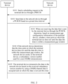
- FIG. 2 is an interaction flowchart of an embodiment of a communication method according to this application. As shown in FIG. 2 , the method in this embodiment may include the following steps.
- a network device sends a scheduling request to a terminal device through a PDCCH, where the scheduling request is used to indicate the terminal device to send data to the network device based on a preset time interval.
- the terminal device sends the data to the network device through a PUSCH based on the preset time interval. Specifically, the network device sends the scheduling request to the terminal device through the PDCCH, where the scheduling request is used to indicate that the terminal device can send the data to the network device. After receiving the scheduling request, the terminal device starts to send the data to the network device at the preset time interval.
- the preset time interval is known to the network device and the terminal device, or is carried in the scheduling request. For example, the time interval is 8 ms.
- the terminal device After receiving the scheduling request, the terminal device initially transmits the data to the network device once through the PUSCH.
- the network device receives, at the preset time interval, the data sent by the terminal device.
- the network device determines, based on measurement gap configuration information of the terminal device, whether a time point at which the terminal device does not send the data this time is within a measurement gap window, where the measurement gap configuration information includes a measurement period of a measurement gap, the measurement gap window, and a measurement start time.
- the network device determines, based on the measurement gap configuration information of the terminal device, whether a time point at which the terminal device initially transmits the data is within the measurement gap window.
- the measurement gap configuration information includes the measurement period of the measurement gap, the measurement gap window, and the measurement start time. For example, if the measurement gap window is 6 ms, and the measurement period is 40 ms, the terminal device performs inter-frequency or inter-RAT measurement for continuous 6 ms in every 40 ms, and the terminal device does not send the data for continuous 6 ms in every 40 ms. Therefore, within the time period of 6 ms, the network device cannot receive the data sent by the terminal device.
- the measurement gap configuration information is configured by the network device for the terminal device. In a configuration manner, the method in this embodiment may further include the following steps.
- the terminal device sends, to the network device, a measurement report that is used to indicate that a signal value of a current serving cell of the terminal device is less than a preset threshold.
- the network device sends the measurement gap configuration information to the terminal device when receiving the measurement report that is sent by the terminal device and that is used to indicate that the signal value of the current serving cell of the terminal device is less than the preset threshold.
- the terminal device when a signal of the current serving cell in which the terminal device is located is relatively weak, that is, the signal value of the current serving cell of the terminal device is less than the preset threshold, the terminal device sends the measurement report to the network device, to notify the network device that the signal of the current serving cell is relatively weak.
- the network device sends the measurement gap configuration information to the terminal device. After receiving the measurement gap configuration information, the terminal device starts inter-frequency or inter-RAT measurement, to perform an inter-frequency or inter-RAT handover.
- the measurement gap configuration information is configured by the network device for the terminal device. Therefore, the network device has known the measurement gap configuration information configured for the terminal device.
- the network device may learn of, based on the scheduling request sent to the terminal device, a time point of each data transmission of the terminal device, and the network device may calculate, from the beginning of the measurement start time, whether the time point at which the terminal device does not send the data this time is within the measurement gap window of 6 ms in the measurement period of 80 ms.
- a redundancy version number used for a next HARQ retransmission may be as follows:
- the network device sends a PDCCH to the terminal device, where the PDCCH carries the redundancy version number.
- the redundancy version number used for the next HARQ retransmission may be specifically indicated to the terminal device by using downlink control information (Downlink Control Information, DCI) 0.
- DCI Downlink Control Information
- the terminal device receives the PDCCH sent by the network device, where the PDCCH carries the redundancy version number.
- the terminal device retransmits the data to the network device based on the received redundancy version number by using a HARQ channel that is occupied and on which the data is not sent this time.
- the method in this embodiment may further include the following steps.
- the network device sets a measurement gap conflict flag for each uplink HARQ channel of the terminal device, and sets an initial value of the measurement gap conflict flag to a first value.
- retransmission on a same HARQ channel is fixedly performed after 8 ms.
- the first value is 0, and the second value is 1.
- a HARQ channel with a value of a measurement gap conflict flag being 0 uses non-adaptive retransmission during a next retransmission.
- the terminal device uses resources of a previous PUSCH transmission for retransmission, and a redundancy version number used during the retransmission does not change accumulatively.
- a HARQ channel with a value of a measurement gap conflict flag being 1 uses adaptive retransmission during a next retransmission.
- the network device sends a redundancy version number used for a next HARQ retransmission to the terminal device.
- the redundancy version number used for the next HARQ retransmission is indicated to the terminal device, so that the terminal device retransmits the data based on the redundancy version number indicated by the network device. Therefore, it can be ensured that redundancy version numbers on a network device side and a terminal device side are consistent, to eliminate a risk that the redundancy version numbers on the network device side and the terminal device side are inconsistent, and reduce a bit error rate of the PUSCH.
- the first value and the second value may be other values. This is not limited in this embodiment of this application.
- a measurement gap conflict flag is set for each HARQ channel, and an initial value of the measurement gap conflict flag is the first value.
- the network device sets the value of the measurement gap conflict flag of the HARQ channel that is occupied by the terminal device and on which the data is not sent this time to the second value. In this way, when each HARQ channel is used to perform data transmission, a manner of performing a next data retransmission on each HARQ channel may be determined based on the value of the measurement gap conflict flag, thereby improving data retransmission efficiency and recording a historical status of each data transmission of the terminal device.
- the network device determines, based on the measurement gap configuration information of the terminal device, whether the time point at which the terminal device does not send the data this time is within the measurement gap window. If yes, the redundancy version number used for the next HARQ retransmission is sent to the terminal device, and the terminal device may retransmit the data based on the redundancy version number indicated by the network device. Therefore, it can be ensured that the redundancy version numbers on the network device side and the terminal device side are consistent, to eliminate the risk that the redundancy version numbers on the network device side and the terminal device side are inconsistent, and reduce the bit error rate of the PUSCH.
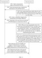
- FIG. 3 is an interaction flowchart of an embodiment of a communication method according to this application. As shown in FIG. 3 , the method in this embodiment may include the following steps.
- a terminal device sends, to a network device, a measurement report that is used to indicate that a signal value of a current serving cell of the terminal device is less than a preset threshold.
- the network device When receiving the measurement report sent by the terminal device, the network device sends measurement gap configuration information to the terminal device, where the measurement gap configuration information includes a measurement period of a measurement gap, a measurement gap window, and measurement start time.
- the terminal device After receiving the measurement gap configuration information, the terminal device starts inter-frequency or inter-RAT measurement, to perform an inter-frequency or inter-RAT handover.
- the network device sets a measurement gap conflict flag for each uplink HARQ channel of the terminal device, and sets an initial value of the measurement gap conflict flag to a first value.
- retransmission on a same HARQ channel is fixedly performed after 8 ms.
- the network device sends a scheduling request to the terminal device through a PDCCH, where the scheduling request is used to indicate the terminal device to send data to the network device based on a preset time interval.
- the preset time interval is known to the network device and the terminal device, or is carried in the scheduling request.
- the terminal device sends the data to the network device through a PUSCH based on the preset time interval. Specifically, after receiving the scheduling request, the terminal device starts to send the data to the network device at the preset time interval. Correspondingly, the network device receives, at the preset time interval, the data sent by the terminal device.
- the network device calculates, based on the measurement period of the measurement gap, the measurement gap window, and the measurement start time, whether a time point at which the terminal device does not send the data this time is within the measurement gap window.
- the network device determines that the time point at which the terminal device does not send the data this time is within the measurement gap window, the network device sets a value of a measurement gap conflict flag of a HARQ channel that is occupied by the terminal device and on which the data is not sent this time to a second value.
- a HARQ channel with a value of a measurement gap conflict flag being the first value uses non-adaptive retransmission during a next retransmission
- a HARQ channel with a value of a measurement gap conflict flag being the second value uses adaptive retransmission during a next retransmission.
- the network device may send a PDCCH to the terminal device, where the PDCCH carries the redundancy version number.
- the terminal device receives the PDCCH sent by the network device, where the PDCCH carries the redundancy version number.
- S209 The terminal device retransmits the data to the network device based on the received redundancy version number by using the HARQ channel.
- the network device sets a measurement gap conflict flag for each uplink HARQ channel of the terminal device, and sets an initial value of the measurement gap conflict flag to the first value.
- the network device calculates, based on the measurement period of the measurement gap, the measurement gap window, and the measurement start time, whether the time point at which the terminal device does not send the data this time is within the measurement gap window. If yes, the network device sets the value of the measurement gap conflict flag of the HARQ channel that is occupied by the terminal device and on which the data is not sent this time to the second value.
- the HARQ channel with the value of the measurement gap conflict flag being the first value uses non-adaptive retransmission during the next retransmission
- the HARQ channel with the value of the measurement gap conflict flag being the second value uses adaptive retransmission during the next retransmission.
- a measurement gap conflict flag whose initial value is the first value is set for each HARQ channel.
- the network device sets the value of the measurement gap conflict flag of the HARQ channel that is occupied by the terminal device and on which the data is not sent this time to the second value.
- a manner of performing a next data retransmission on each HARQ channel may be determined based on the value of the measurement gap conflict flag, thereby improving data retransmission efficiency and recording a historical status of each data transmission of the terminal device.
- an operation performed by the terminal device may alternatively be implemented by a component (for example, a chip or a circuit) that may be used in a terminal
- an operation performed by the network device may alternatively be implemented by a component (for example, a chip or a circuit) that may be used in a network device.
- FIG. 4 is a schematic structural diagram of an embodiment of a network device according to this application.
- the network device may alternatively be a component (for example, a chip or a circuit) that may be used in a network device.
- the network device in this embodiment may include: a sending module 11 and a processing module 12.
- the sending module 11 is configured to send a scheduling request to a terminal device through a PDCCH, where the scheduling request is used to indicate the terminal device to send data to the network device based on a preset time interval.
- the processing module 12 is configured to: when not receiving the data that is sent by the terminal device through a PUSCH, determine, based on measurement gap configuration information of the terminal device, whether a time point at which the terminal device does not send the data this time is within a measurement gap window, where the measurement gap configuration information includes a measurement period of a measurement gap, the measurement gap window, and a measurement start time.
- the sending module 11 is further configured to: if the processing module 12 determines that the time point at which the terminal device does not send the data this time is within the measurement gap window, send, to the terminal device, a redundancy version number used for a next hybrid automatic repeat request HARQ retransmission.
- the sending module 11 is further configured to: send the measurement gap configuration information to the terminal device when a measurement report that is sent by the terminal device and that is used to indicate that a signal value of a current serving cell of the terminal device is less than a preset threshold is received.
- the processing module 12 is configured to: calculate, based on the measurement period of the measurement gap, the measurement gap window, and the measurement start time, whether the time point at which the terminal device does not send the data this time is within the measurement gap window.
- processing module 12 is further configured to:
- a HARQ channel with a value of a measurement gap conflict flag being the first value uses non-adaptive retransmission during a next retransmission
- a HARQ channel with a value of a measurement gap conflict flag being the second value uses adaptive retransmission during a next retransmission.
- the sending module 11 is specifically configured to: send a PDCCH to the terminal device, where the PDCCH carries the redundancy version number.
- the network device in this embodiment may be configured to perform the technical solution in the method embodiment shown in FIG. 2 or FIG. 3 , and implementation principles and technical effects thereof are similar.
- each module For an operation implemented by each module, refer to related descriptions in the method embodiments. Details are not described herein again.
- the module herein may alternatively be replaced with a component or a circuit.
- FIG. 5 is a schematic structural diagram of an embodiment of a terminal device according to this application.
- the terminal device may alternatively be a component (for example, a chip or a circuit) that may be used in a terminal device.
- the terminal device in this embodiment may include: a receiving module 21 and a sending module 22.
- the receiving module 21 is configured to receive a scheduling request that is sent by a network device through a physical downlink control channel PDCCH.
- the sending module 22 is configured to send data to the network device through a physical uplink shared channel PUSCH based on a preset time interval.
- the receiving module 21 is further configured to receive a redundancy version number that is used for a next hybrid automatic repeat request HARQ retransmission and that is sent by the network device.
- the redundancy version number is sent when the network device does not receive the data that is sent by the terminal device through the PUSCH, and determines, based on measurement gap configuration information of the terminal device, that a time point at which the terminal device does not send the data this time is within a measurement gap window, and the measurement gap configuration information includes a measurement period of a measurement gap, the measurement gap window, and a measurement start time.
- the sending module 22 is further configured to retransmit the data to the network device based on the redundancy version number by using a HARQ channel that is occupied and on which the data is not sent this time.
- the sending module 22 is further configured to:
- the receiving module 21 is specifically configured to: receive a PDCCH sent by the network device, where the PDCCH carries the redundancy version number.
- the terminal device in this embodiment may be configured to perform the technical solution in the method embodiment shown in FIG. 2 or FIG. 3 , and implementation principles and technical effects thereof are similar.
- the module herein may alternatively be replaced with a component or a circuit.
- each functional module may be divided corresponding to each function, or two or more functions may be integrated into one processing module.
- the integrated module may be implemented in a form of hardware, or may be implemented in a form of a software functional module. It should be noted that, in the embodiments of this application, division into the modules is an example, and is merely a logical function division. During actual implementation, another division manner may be used.
- FIG. 6 is a schematic structural diagram of a network device according to this application.
- the network device 200 includes:
- the network device 200 may further include an input/output interface 203.
- the input/output interface 203 may include an independent output interface and an independent input interface, or may be an integrated interface integrating input and output.
- the output interface is configured to output data, and the input interface is configured to obtain input data.
- the output data is a general term of output in the foregoing method embodiments, and the input data is a general term of input in the foregoing method embodiments.
- the network device 200 may be configured to perform the steps and/or procedures corresponding to the network device in the foregoing method embodiments.
- FIG. 7 is a schematic structural diagram of a terminal device according to this application.
- the terminal device 300 includes:
- the terminal device 300 may further include an input/output interface 303.
- the input/output interface 303 may include an independent output interface and an independent input interface, or may be an integrated interface integrating input and output.
- the output interface is configured to output data, and the input interface is configured to obtain input data.
- the output data is a general term of output in the foregoing method embodiments, and the input data is a general term of input in the foregoing method embodiments.
- the terminal device 300 may be configured to perform the steps and/or procedures corresponding to the terminal device in the foregoing method embodiments.
- This application further provides a readable storage medium.
- the readable storage medium stores executable instructions.
- the network device executes the executable instructions, the network device performs the communication method in the foregoing method embodiments.
- This application further provides a readable storage medium.
- the readable storage medium stores executable instructions.
- the terminal device executes the executable instructions, the terminal device performs the communication method in the foregoing method embodiments.
- This application further provides a program product.
- the program product includes executable instructions, and the executable instructions are stored in a readable storage medium.
- At least one processor of a network device may read the executable instructions in the readable storage medium, and the at least one processor executes the executable instructions, so that the network device implements the communication method in the foregoing method embodiments.
- This application further provides a program product.
- the program product includes executable instructions, and the executable instructions are stored in a readable storage medium.
- At least one processor of a terminal device may read the executable instructions in the readable storage medium, and the at least one processor executes the executable instructions, so that the terminal device implements the communication method in the foregoing method embodiments.
- This application further provides a chip. The chip is connected to a memory, or a memory is integrated into the chip. When a software program stored in the memory is executed, the communication method in the foregoing method embodiments is implemented.
- the embodiments may be implemented completely or partially in a form of a computer program product.
- the computer program product includes one or more computer instructions.
- the computer may be a general-purpose computer, a dedicated computer, a computer network, or another programmable apparatus.
- the computer instructions may be stored in a computer-readable storage medium or may be transmitted from a computer-readable storage medium to another computer-readable storage medium.
- the computer instructions may be transmitted from a website, computer, server, or data center to another website, computer, server, or data center in a wired (for example, a coaxial cable, an optical fiber, or a digital subscriber line (DSL)) or wireless (for example, infrared, radio, or microwave) manner.
- the computer-readable storage medium may be any usable medium accessible by a computer, or a data storage device, such as a server or a data center, integrating one or more usable media.
- the usable medium may be a magnetic medium (for example, a floppy disk, a hard disk, or a magnetic tape), an optical medium (for example, a DVD), a semiconductor medium (for example, a solid-state drive (Solid State Disk, SSD)), or the like.
- a magnetic medium for example, a floppy disk, a hard disk, or a magnetic tape
- an optical medium for example, a DVD
- a semiconductor medium for example, a solid-state drive (Solid State Disk, SSD)
Landscapes
- Engineering & Computer Science (AREA)
- Computer Networks & Wireless Communication (AREA)
- Signal Processing (AREA)
- Mobile Radio Communication Systems (AREA)
Claims (15)
- Kommunikationsverfahren, umfassend:Senden einer Planungsanforderung an eine Endgerätevorrichtung (300) über einen physischen Downlink-Steuerkanal, PDCCH, wobei die Planungsanforderung dazu verwendet wird, der Endgerätevorrichtung (300) anzuzeigen, einer Netzvorrichtung (200) basierend auf einem voreingestellten Zeitintervall Daten zuzusenden;wenn die Daten von der Endgerätevorrichtung (300) nicht über einen physischen gemeinsam genutzten Uplink-Kanal, PUSCH, empfangen werden, Bestimmen, basierend auf Messlückenkonfigurationsinformationen der Endgerätevorrichtung (300), ob ein Zeitpunkt, zu dem die Endgerätevorrichtung (300) die Daten diesmal nicht sendet, innerhalb eines Messlückenfensters liegt, wobei die Messlückenkonfigurationsinformationen einen Messzeitraum einer Messlücke, das Messlückenfenster und eine Messstartzeit umfassen; undwenn bestimmt wird, dass der Zeitpunkt, zu dem die Endgerätevorrichtung (300) die Daten diesmal nicht sendet, innerhalb des Messlückenfensters liegt, Senden, an die Endgerätevorrichtung (300), einer Redundanzversionsnummer, die für eine nächste hybride automatische Wiederholungsanforderungsneuübertragung, HARQ-Neuübertragung, verwendet wird.
- Verfahren nach Anspruch 1, wobei das Verfahren ferner Folgendes umfasst:
Senden der Messlückenkonfigurationsinformationen an die Endgerätevorrichtung (300) nach Empfangen eines Messberichts, der durch die Endgerätevorrichtung (300) gesandt wird und der dazu verwendet wird, anzuzeigen, dass ein Signalwert einer aktuellen bedienenden Zelle der Endgerätevorrichtung (300) kleiner als ein voreingestellter Schwellenwert ist. - Verfahren nach Anspruch 1 oder 2, wobei das Bestimmen, basierend auf Messlückenkonfigurationsinformationen der Endgerätevorrichtung (300), ob ein Zeitpunkt, zu dem die Endgerätevorrichtung (300) die Daten diesmal nicht sendet, innerhalb eines Messlückenfensters liegt, Folgendes umfasst:
Berechnen, basierend auf dem Messzeitraum der Messlücke, dem Messlückenfenster und der Messstartzeit, ob der Zeitpunkt, zu dem die Endgerätevorrichtung (300) die Daten diesmal nicht sendet, innerhalb des Messlückenfensters liegt. - Verfahren nach Anspruch 1, wobei das Verfahren ferner Folgendes umfasst:Setzen eines Messlückenkonflikt-Flags für jeden Uplink-HARQ-Kanal der Endgerätevorrichtung (300) und Setzen eines Anfangswerts des Messlückenkonflikt-Flags auf einen ersten Wert; undwenn bestimmt wird, dass der Zeitpunkt, zu dem die Endgerätevorrichtung (300) die Daten diesmal nicht sendet, innerhalb des Messlückenfensters liegt, Setzen eines Wertes eines Messlückenkonflikt-Flags eines HARQ-Kanals, der durch die Endgerätevorrichtung (300) belegt ist und auf dem die Daten diesmal nicht gesandt werden, auf einen zweiten Wert, wobeiein HARQ-Kanal mit einem Wert eines Messlückenkonflikt-Flags, der der erste Wert ist, während einer nächsten Neuübertragung nichtadaptive Neuübertragung verwendet und ein HARQ-Kanal mit einem Wert eines Messlückenkonflikt-Flags, der der zweite Wert ist, während einer nächsten Neuübertragung adaptive Neuübertragung verwendet.
- Verfahren nach einem der Ansprüche 1 bis 4, wobei das Senden, an die Endgerätevorrichtung (300), einer Redundanzversionsnummer, die für eine nächste hybride automatische Wiederholungsanforderungsneuübertragung, HARQ-Neuübertragung, verwendet wird, Folgendes umfasst:
Senden eines PDCCH an die Endgerätevorrichtung (300), wobei der PDCCH die Redundanzversionsnummer trägt. - Kommunikationsverfahren, umfassend:nach Empfangen einer Planungsanforderung, die durch eine Netzvorrichtung (200) über einen physischen Downlink-Steuerkanal, PDCCH, gesandt wird, Senden von Daten an die Netzvorrichtung (200) über einen physischen gemeinsam genutzten Uplink-Kanal, PUSCH, basierend auf einem voreingestellten Zeitintervall;Empfangen einer Redundanzversionsnummer, die für eine nächste hybride automatische Wiederholungsanforderungsneuübertragung, HARQ-Neuübertragung, verwendet wird und die durch die Netzvorrichtung (200) gesandt wird, wobei die Redundanzversionsnummer gesandt wird, wenn die Netzvorrichtung (200) die Daten von einer Endgerätevorrichtung (300) nicht über den PUSCH empfängt, und bestimmt, basierend auf Messlückenkonfigurationsinformationen der Endgerätevorrichtung (300), dass ein Zeitpunkt, zu dem die Endgerätevorrichtung (300) die Daten diesmal nicht sendet, innerhalb eines Messlückenfensters liegt, und die Messlückenkonfigurationsinformationen einen Messzeitraum einer Messlücke, das Messlückenfenster und eine Messstartzeit umfassen; undNeuübertragen der Daten an die Netzvorrichtung (200) basierend auf der Redundanzversionsnummer unter Verwendung eines HARQ-Kanals, der belegt ist und auf dem die Daten diesmal nicht gesandt werden.
- Verfahren nach Anspruch 6, wobei das Verfahren ferner Folgendes umfasst:Senden, an die Netzvorrichtung (200), eines Messberichts, der dazu verwendet wird, anzuzeigen, dass ein Signalwert einer aktuellen bedienenden Zelle der Endgerätevorrichtung (300) kleiner als ein voreingestellter Schwellenwert ist; undEmpfangen der Messlückenkonfigurationsinformationen, die durch die Netzvorrichtung (200) gesandt werden.
- Verfahren nach Anspruch 6 oder 7, wobei das Empfangen einer Redundanzversionsnummer, die für eine nächste hybride automatische Wiederholungsanforderungsneuübertragung, HARQ-Neuübertragung, verwendet wird und die durch die Netzvorrichtung (200) gesandt wird, Folgendes umfasst:
Empfangen eines PDCCH, der durch die Netzvorrichtung (200) gesandt wird, wobei der PDCCH die Redundanzversionsnummer trägt. - Netzvorrichtung (200), umfassend:ein Sendemodul (11), das dazu konfiguriert ist, eine Planungsanforderung über einen physischen Downlink-Steuerkanal, PDCCH, an eine Endgerätevorrichtung (300) zu senden, wobei die Planungsanforderung dazu verwendet wird, der Endgerätevorrichtung (300) anzuzeigen, der Netzvorrichtung (200) basierend auf einem voreingestellten Zeitintervall Daten zuzusenden; undein Verarbeitungsmodul (12), das zu Folgendem konfiguriert ist: wenn die Daten von der Endgerätevorrichtung (300) nicht über einen physischen gemeinsam genutzten Uplink-Kanal, PUSCH, empfangen werden, Bestimmen, basierend auf Messlückenkonfigurationsinformationen der Endgerätevorrichtung (300), ob ein Zeitpunkt, zu dem die Endgerätevorrichtung (300) die Daten diesmal nicht sendet, innerhalb eines Messlückenfensters liegt, wobei die Messlückenkonfigurationsinformationen einen Messzeitraum einer Messlücke, das Messlückenfenster und eine Messstartzeit umfassen; wobeidas Sendemodul (11) ferner zu Folgendem konfiguriert ist: wenn das Verarbeitungsmodul (12) bestimmt, dass der Zeitpunkt, zu dem die Endgerätevorrichtung (300) die Daten diesmal nicht sendet, innerhalb des Messlückenfensters liegt, Senden, an die Endgerätevorrichtung (300), einer Redundanzversionsnummer, die für eine nächste hybride automatische Wiederholungsanforderungsneuübertragung, HARQ-Neuübertragung, verwendet wird.
- Netzvorrichtung (200) nach Anspruch 9, wobei das Sendemodul (11) ferner zu Folgendem konfiguriert ist:
Senden der Messlückenkonfigurationsinformationen an die Endgerätevorrichtung (300) nachdem ein Messbericht, der durch die Endgerätevorrichtung (300) gesandt wird und der dazu verwendet wird, anzuzeigen, dass ein Signalwert einer aktuellen bedienenden Zelle der Endgerätevorrichtung (300) kleiner als ein voreingestellter Schwellenwert ist, empfangen wird. - Netzvorrichtung (200) nach Anspruch 9 oder 10, wobei das Verarbeitungsmodul (12) zu Folgendem konfiguriert ist:
Berechnen, basierend auf dem Messzeitraum der Messlücke, dem Messlückenfenster und der Messstartzeit, ob der Zeitpunkt, zu dem die Endgerätevorrichtung (300) die Daten diesmal nicht sendet, innerhalb des Messlückenfensters liegt. - Netzvorrichtung (200) nach Anspruch 9, wobei das Verarbeitungsmodul (12) ferner zu Folgendem konfiguriert ist:Setzen eines Messlückenkonflikt-Flags für jeden Uplink-HARQ-Kanal der Endgerätevorrichtung (300) und Setzen eines Anfangswerts des Messlückenkonflikt-Flags auf einen ersten Wert; undwenn bestimmt wird, dass der Zeitpunkt, zu dem die Endgerätevorrichtung (300) die Daten diesmal nicht sendet, innerhalb des Messlückenfensters liegt, Setzen eines Wertes eines Messlückenkonflikt-Flags eines HARQ-Kanals, der durch die Endgerätevorrichtung (300) belegt ist und auf dem die Daten diesmal nicht gesandt werden, auf einen zweiten Wert, wobeiein HARQ-Kanal mit einem Wert eines Messlückenkonflikt-Flags, der der erste Wert ist, während einer nächsten Neuübertragung nichtadaptive Neuübertragung verwendet und ein HARQ-Kanal mit einem Wert eines Messlückenkonflikt-Flags, der der zweite Wert ist, während einer nächsten Neuübertragung adaptive Neuübertragung verwendet.
- Endgerätevorrichtung (300), umfassend:ein Empfangsmodul (21), das dazu konfiguriert ist, eine Planungsanforderung zu empfangen, die durch eine Netzvorrichtung (200) über einen physischen Downlink-Steuerkanal, PDCCH, gesandt wird; undein Sendemodul (22), das dazu konfiguriert ist, der Netzvorrichtung (200) Daten über einen physischen gemeinsam genutzten Uplink-Kanal, PUSCH, basierend auf einem voreingestellten Zeitintervall zuzusenden, wobeidas Empfangsmodul (21) ferner dazu konfiguriert ist, eine Redundanzversionsnummer zu empfangen, die für eine nächste hybride automatische Wiederholungsanforderungsneuübertragung, HARQ-Neuübertragung, verwendet wird und die durch die Netzvorrichtung (200) gesandt wird, wobei die Redundanzversionsnummer gesandt wird, wenn die Netzvorrichtung (200) die Daten von der Endgerätevorrichtung (300) nicht über den PUSCH empfängt, und bestimmt, basierend auf Messlückenkonfigurationsinformationen der Endgerätevorrichtung (300), dass ein Zeitpunkt, zu dem die Endgerätevorrichtung (300) die Daten diesmal nicht sendet, innerhalb eines Messlückenfensters liegt, und die Messlückenkonfigurationsinformationen einen Messzeitraum einer Messlücke, das Messlückenfenster und eine Messstartzeit umfassen; unddas Sendemodul (22) ferner dazu konfiguriert ist, die Daten an die Netzvorrichtung (200) basierend auf der Redundanzversionsnummer unter Verwendung eines HARQ-Kanals, der belegt ist und auf dem die Daten diesmal nicht gesandt werden, neu zu übertragen.
- Endgerätevorrichtung (300) nach Anspruch 13, wobei das Sendemodul (22) ferner zu Folgendem konfiguriert ist:Senden, an die Netzvorrichtung (200), eines Messberichts, der dazu verwendet wird, anzuzeigen, dass ein Signalwert einer aktuellen bedienenden Zelle der Endgerätevorrichtung (300) kleiner als ein voreingestellter Schwellenwert ist; unddas Empfangsmodul (21) ferner dazu konfiguriert ist, die Messlückenkonfigurationsinformationen, die durch die Netzvorrichtung (200) gesandt werden, zu empfangen.
- Endgerätevorrichtung (300) nach Anspruch 13 oder 14, wobei das Empfangsmodul (21) ferner zu Folgendem konfiguriert ist:
Empfangen eines PDCCH, der durch die Netzvorrichtung (200) gesandt wird, wobei der PDCCH die Redundanzversionsnummer trägt.
Applications Claiming Priority (1)
| Application Number | Priority Date | Filing Date | Title |
|---|---|---|---|
| PCT/CN2018/117986 WO2020107278A1 (zh) | 2018-11-28 | 2018-11-28 | 通信方法及装置 |
Publications (3)
| Publication Number | Publication Date |
|---|---|
| EP3869717A1 EP3869717A1 (de) | 2021-08-25 |
| EP3869717A4 EP3869717A4 (de) | 2021-10-27 |
| EP3869717B1 true EP3869717B1 (de) | 2024-10-30 |
Family
ID=70854231
Family Applications (1)
| Application Number | Title | Priority Date | Filing Date |
|---|---|---|---|
| EP18941478.2A Active EP3869717B1 (de) | 2018-11-28 | 2018-11-28 | Kommunikationsverfahren und -vorrichtung |
Country Status (4)
| Country | Link |
|---|---|
| US (1) | US11882566B2 (de) |
| EP (1) | EP3869717B1 (de) |
| CN (1) | CN112602281B (de) |
| WO (1) | WO2020107278A1 (de) |
Families Citing this family (8)
| Publication number | Priority date | Publication date | Assignee | Title |
|---|---|---|---|---|
| CN111385836B (zh) * | 2018-12-29 | 2022-05-27 | 大唐移动通信设备有限公司 | 一种信息配置和数据传输的方法及设备 |
| CN114175716B (zh) * | 2019-07-19 | 2023-09-19 | Lg电子株式会社 | 在无线通信系统中由用户设备执行测量的方法和设备 |
| CN113300802B (zh) * | 2020-02-21 | 2022-10-04 | 中国移动通信有限公司研究院 | 传输方法及设备 |
| WO2022205319A1 (en) * | 2021-04-01 | 2022-10-06 | Apple Inc. | Configuration of multiple measurement gaps for a ue |
| CN115209557A (zh) * | 2021-04-09 | 2022-10-18 | 华为技术有限公司 | 一种传输数据的方法及装置 |
| CN115379472A (zh) * | 2021-05-18 | 2022-11-22 | 维沃移动通信有限公司 | 测量间隙的确定方法、终端及网络侧设备 |
| CN116155463A (zh) * | 2021-11-19 | 2023-05-23 | 维沃移动通信有限公司 | Gap窗口的配置方法、装置、设备及介质 |
| US20250212037A1 (en) * | 2022-04-13 | 2025-06-26 | Mediatek Inc. | Method and apparatus for data scheduling within measurement gaps |
Family Cites Families (12)
| Publication number | Priority date | Publication date | Assignee | Title |
|---|---|---|---|---|
| KR101025072B1 (ko) * | 2004-12-30 | 2011-03-25 | 엘지에릭슨 주식회사 | 에이치에이알큐 방식을 사용하는 통신 시스템에서 최적의리던던시 버전 선택 방법 |
| CN101796761B (zh) * | 2007-08-14 | 2014-07-16 | 诺基亚公司 | 实现部分受限重传的资源调度 |
| WO2009157729A2 (en) * | 2008-06-27 | 2009-12-30 | Samsung Electronics Co., Ltd. | A method of timing the harq feedback when the corresponding transmission overlaps with the measurement gaps in a wireless communication system |
| US9270409B2 (en) * | 2012-03-09 | 2016-02-23 | Blackberry Limited | System and method for handling of an uplink transmission collision with an ACK/NACK signal |
| WO2014084638A1 (en) * | 2012-11-28 | 2014-06-05 | Samsung Electronics Co., Ltd. | Method and apparatus for performing communication in a wireless communication system |
| CN103973418B (zh) * | 2013-01-29 | 2018-10-19 | 中兴通讯股份有限公司 | 一种基于信道激活检测的传输方法及装置 |
| US9451639B2 (en) * | 2013-07-10 | 2016-09-20 | Samsung Electronics Co., Ltd. | Method and apparatus for coverage enhancement for a random access process |
| KR102369016B1 (ko) * | 2014-01-29 | 2022-03-03 | 삼성전자주식회사 | 이동 통신 시스템에서 복수의 캐리어를 이용하는 데이터 송수신 방법 및 장치 |
| US20150327295A1 (en) * | 2014-05-12 | 2015-11-12 | Qualcomm Incorporated | Inter radio access technology measurement gap |
| EP3353933B1 (de) * | 2015-09-24 | 2020-02-19 | Telefonaktiebolaget LM Ericsson (PUBL) | Lte-harq-rückkopplung für konfigurierte uplink-genehmigungen |
| CN107889231B (zh) * | 2016-09-30 | 2021-03-23 | 华为技术有限公司 | 免授权的传输上行信息的方法、网络设备和终端设备 |
| CN108809547B (zh) * | 2017-05-05 | 2020-09-01 | 维沃移动通信有限公司 | 一种数据传输方法、基站及终端 |
-
2018
- 2018-11-28 WO PCT/CN2018/117986 patent/WO2020107278A1/zh not_active Ceased
- 2018-11-28 CN CN201880096454.XA patent/CN112602281B/zh active Active
- 2018-11-28 EP EP18941478.2A patent/EP3869717B1/de active Active
-
2021
- 2021-05-21 US US17/326,896 patent/US11882566B2/en active Active
Also Published As
| Publication number | Publication date |
|---|---|
| EP3869717A1 (de) | 2021-08-25 |
| US20210289537A1 (en) | 2021-09-16 |
| EP3869717A4 (de) | 2021-10-27 |
| US11882566B2 (en) | 2024-01-23 |
| CN112602281A (zh) | 2021-04-02 |
| CN112602281B (zh) | 2021-11-09 |
| WO2020107278A1 (zh) | 2020-06-04 |
Similar Documents
| Publication | Publication Date | Title |
|---|---|---|
| US11882566B2 (en) | Communications method and apparatus | |
| CN114071776B (zh) | 通信方法、用户设备、网络设备及电子设备 | |
| US9270409B2 (en) | System and method for handling of an uplink transmission collision with an ACK/NACK signal | |
| KR102035402B1 (ko) | 자동 재송신 요청(arq) 피드백 정보를 처리하기 위한 네트워크 노드, 무선 장치 및 그 방법들 | |
| US11006462B2 (en) | System and method for handling of an uplink transmission collision with an ACK/NACK signal | |
| EP3703298B1 (de) | Informationsübertragungsverfahren und -vorrichtung | |
| WO2019091233A1 (zh) | 一种带宽切换方法及装置 | |
| US20190349144A1 (en) | Transmission mode switching method and apparatus | |
| US20220322368A1 (en) | Method and terminal for data transmission using unlicensed carrier | |
| TWI793471B (zh) | 信號傳輸方法及裝置 | |
| US11463207B2 (en) | Data transmission method, receive end device, and non-transitory computer-readable storage medium | |
| JP6397059B2 (ja) | ユーザ装置及び基地局 | |
| JPWO2016189916A1 (ja) | 基地局 | |
| EP3531762A1 (de) | Nachrichtenrückmeldungsverfahren und -vorrichtung für trägeraggregation | |
| EP3487230B1 (de) | Senden und empfangen von uplink-scheduling-informationen | |
| CN115941124B (zh) | Harq-ack反馈方法和装置 | |
| WO2014179980A1 (zh) | 混合自动重传请求harq反馈方法、用户设备及基站 | |
| CN107333336A (zh) | 一种在随机接入信道上发送前导序列的方法、基站及终端 | |
| US10567121B2 (en) | Low latency service feedback method and communications device |
Legal Events
| Date | Code | Title | Description |
|---|---|---|---|
| STAA | Information on the status of an ep patent application or granted ep patent |
Free format text: STATUS: THE INTERNATIONAL PUBLICATION HAS BEEN MADE |
|
| PUAI | Public reference made under article 153(3) epc to a published international application that has entered the european phase |
Free format text: ORIGINAL CODE: 0009012 |
|
| STAA | Information on the status of an ep patent application or granted ep patent |
Free format text: STATUS: REQUEST FOR EXAMINATION WAS MADE |
|
| 17P | Request for examination filed |
Effective date: 20210521 |
|
| AK | Designated contracting states |
Kind code of ref document: A1 Designated state(s): AL AT BE BG CH CY CZ DE DK EE ES FI FR GB GR HR HU IE IS IT LI LT LU LV MC MK MT NL NO PL PT RO RS SE SI SK SM TR |
|
| A4 | Supplementary search report drawn up and despatched |
Effective date: 20210924 |
|
| RIC1 | Information provided on ipc code assigned before grant |
Ipc: H04W 72/14 20090101ALI20210920BHEP Ipc: H04W 24/00 20090101ALI20210920BHEP Ipc: H04L 1/18 20060101AFI20210920BHEP |
|
| DAV | Request for validation of the european patent (deleted) | ||
| DAX | Request for extension of the european patent (deleted) | ||
| REG | Reference to a national code |
Ref country code: DE Free format text: PREVIOUS MAIN CLASS: H04L0001180000 Ref country code: DE Ref legal event code: R079 Ref document number: 602018076147 Country of ref document: DE Free format text: PREVIOUS MAIN CLASS: H04L0001180000 Ipc: H04L0001181200 |
|
| GRAP | Despatch of communication of intention to grant a patent |
Free format text: ORIGINAL CODE: EPIDOSNIGR1 |
|
| STAA | Information on the status of an ep patent application or granted ep patent |
Free format text: STATUS: GRANT OF PATENT IS INTENDED |
|
| RIC1 | Information provided on ipc code assigned before grant |
Ipc: H04W 24/10 20090101ALI20240522BHEP Ipc: H04L 1/1825 20230101ALI20240522BHEP Ipc: H04L 1/1812 20230101AFI20240522BHEP |
|
| INTG | Intention to grant announced |
Effective date: 20240613 |
|
| GRAS | Grant fee paid |
Free format text: ORIGINAL CODE: EPIDOSNIGR3 |
|
| GRAA | (expected) grant |
Free format text: ORIGINAL CODE: 0009210 |
|
| STAA | Information on the status of an ep patent application or granted ep patent |
Free format text: STATUS: THE PATENT HAS BEEN GRANTED |
|
| AK | Designated contracting states |
Kind code of ref document: B1 Designated state(s): AL AT BE BG CH CY CZ DE DK EE ES FI FR GB GR HR HU IE IS IT LI LT LU LV MC MK MT NL NO PL PT RO RS SE SI SK SM TR |
|
| REG | Reference to a national code |
Ref country code: GB Ref legal event code: FG4D |
|
| REG | Reference to a national code |
Ref country code: CH Ref legal event code: EP |
|
| REG | Reference to a national code |
Ref country code: IE Ref legal event code: FG4D |
|
| REG | Reference to a national code |
Ref country code: DE Ref legal event code: R096 Ref document number: 602018076147 Country of ref document: DE |
|
| REG | Reference to a national code |
Ref country code: LT Ref legal event code: MG9D |
|
| REG | Reference to a national code |
Ref country code: NL Ref legal event code: MP Effective date: 20241030 |
|
| PG25 | Lapsed in a contracting state [announced via postgrant information from national office to epo] |
Ref country code: PT Free format text: LAPSE BECAUSE OF FAILURE TO SUBMIT A TRANSLATION OF THE DESCRIPTION OR TO PAY THE FEE WITHIN THE PRESCRIBED TIME-LIMIT Effective date: 20250228 Ref country code: IS Free format text: LAPSE BECAUSE OF FAILURE TO SUBMIT A TRANSLATION OF THE DESCRIPTION OR TO PAY THE FEE WITHIN THE PRESCRIBED TIME-LIMIT Effective date: 20250228 Ref country code: HR Free format text: LAPSE BECAUSE OF FAILURE TO SUBMIT A TRANSLATION OF THE DESCRIPTION OR TO PAY THE FEE WITHIN THE PRESCRIBED TIME-LIMIT Effective date: 20241030 |
|
| PG25 | Lapsed in a contracting state [announced via postgrant information from national office to epo] |
Ref country code: FI Free format text: LAPSE BECAUSE OF FAILURE TO SUBMIT A TRANSLATION OF THE DESCRIPTION OR TO PAY THE FEE WITHIN THE PRESCRIBED TIME-LIMIT Effective date: 20241030 Ref country code: NL Free format text: LAPSE BECAUSE OF FAILURE TO SUBMIT A TRANSLATION OF THE DESCRIPTION OR TO PAY THE FEE WITHIN THE PRESCRIBED TIME-LIMIT Effective date: 20241030 |
|
| REG | Reference to a national code |
Ref country code: AT Ref legal event code: MK05 Ref document number: 1737965 Country of ref document: AT Kind code of ref document: T Effective date: 20241030 |
|
| PG25 | Lapsed in a contracting state [announced via postgrant information from national office to epo] |
Ref country code: BG Free format text: LAPSE BECAUSE OF FAILURE TO SUBMIT A TRANSLATION OF THE DESCRIPTION OR TO PAY THE FEE WITHIN THE PRESCRIBED TIME-LIMIT Effective date: 20241030 |
|
| PG25 | Lapsed in a contracting state [announced via postgrant information from national office to epo] |
Ref country code: ES Free format text: LAPSE BECAUSE OF FAILURE TO SUBMIT A TRANSLATION OF THE DESCRIPTION OR TO PAY THE FEE WITHIN THE PRESCRIBED TIME-LIMIT Effective date: 20241030 |
|
| PG25 | Lapsed in a contracting state [announced via postgrant information from national office to epo] |
Ref country code: NO Free format text: LAPSE BECAUSE OF FAILURE TO SUBMIT A TRANSLATION OF THE DESCRIPTION OR TO PAY THE FEE WITHIN THE PRESCRIBED TIME-LIMIT Effective date: 20250130 |
|
| PG25 | Lapsed in a contracting state [announced via postgrant information from national office to epo] |
Ref country code: AT Free format text: LAPSE BECAUSE OF FAILURE TO SUBMIT A TRANSLATION OF THE DESCRIPTION OR TO PAY THE FEE WITHIN THE PRESCRIBED TIME-LIMIT Effective date: 20241030 Ref country code: GR Free format text: LAPSE BECAUSE OF FAILURE TO SUBMIT A TRANSLATION OF THE DESCRIPTION OR TO PAY THE FEE WITHIN THE PRESCRIBED TIME-LIMIT Effective date: 20250131 Ref country code: LV Free format text: LAPSE BECAUSE OF FAILURE TO SUBMIT A TRANSLATION OF THE DESCRIPTION OR TO PAY THE FEE WITHIN THE PRESCRIBED TIME-LIMIT Effective date: 20241030 |
|
| PG25 | Lapsed in a contracting state [announced via postgrant information from national office to epo] |
Ref country code: PL Free format text: LAPSE BECAUSE OF FAILURE TO SUBMIT A TRANSLATION OF THE DESCRIPTION OR TO PAY THE FEE WITHIN THE PRESCRIBED TIME-LIMIT Effective date: 20241030 |
|
| PG25 | Lapsed in a contracting state [announced via postgrant information from national office to epo] |
Ref country code: RS Free format text: LAPSE BECAUSE OF FAILURE TO SUBMIT A TRANSLATION OF THE DESCRIPTION OR TO PAY THE FEE WITHIN THE PRESCRIBED TIME-LIMIT Effective date: 20250130 |
|
| REG | Reference to a national code |
Ref country code: CH Ref legal event code: PL |
|
| PG25 | Lapsed in a contracting state [announced via postgrant information from national office to epo] |
Ref country code: SM Free format text: LAPSE BECAUSE OF FAILURE TO SUBMIT A TRANSLATION OF THE DESCRIPTION OR TO PAY THE FEE WITHIN THE PRESCRIBED TIME-LIMIT Effective date: 20241030 |
|
| PG25 | Lapsed in a contracting state [announced via postgrant information from national office to epo] |
Ref country code: MC Free format text: LAPSE BECAUSE OF FAILURE TO SUBMIT A TRANSLATION OF THE DESCRIPTION OR TO PAY THE FEE WITHIN THE PRESCRIBED TIME-LIMIT Effective date: 20241030 |
|
| PG25 | Lapsed in a contracting state [announced via postgrant information from national office to epo] |
Ref country code: DK Free format text: LAPSE BECAUSE OF FAILURE TO SUBMIT A TRANSLATION OF THE DESCRIPTION OR TO PAY THE FEE WITHIN THE PRESCRIBED TIME-LIMIT Effective date: 20241030 |
|
| PG25 | Lapsed in a contracting state [announced via postgrant information from national office to epo] |
Ref country code: LU Free format text: LAPSE BECAUSE OF NON-PAYMENT OF DUE FEES Effective date: 20241128 |
|
| REG | Reference to a national code |
Ref country code: CH Ref legal event code: PL |
|
| PG25 | Lapsed in a contracting state [announced via postgrant information from national office to epo] |
Ref country code: EE Free format text: LAPSE BECAUSE OF FAILURE TO SUBMIT A TRANSLATION OF THE DESCRIPTION OR TO PAY THE FEE WITHIN THE PRESCRIBED TIME-LIMIT Effective date: 20241030 |
|
| PG25 | Lapsed in a contracting state [announced via postgrant information from national office to epo] |
Ref country code: CH Free format text: LAPSE BECAUSE OF NON-PAYMENT OF DUE FEES Effective date: 20241130 |
|
| PG25 | Lapsed in a contracting state [announced via postgrant information from national office to epo] |
Ref country code: RO Free format text: LAPSE BECAUSE OF FAILURE TO SUBMIT A TRANSLATION OF THE DESCRIPTION OR TO PAY THE FEE WITHIN THE PRESCRIBED TIME-LIMIT Effective date: 20241030 |
|
| PG25 | Lapsed in a contracting state [announced via postgrant information from national office to epo] |
Ref country code: SK Free format text: LAPSE BECAUSE OF FAILURE TO SUBMIT A TRANSLATION OF THE DESCRIPTION OR TO PAY THE FEE WITHIN THE PRESCRIBED TIME-LIMIT Effective date: 20241030 |
|
| PG25 | Lapsed in a contracting state [announced via postgrant information from national office to epo] |
Ref country code: CZ Free format text: LAPSE BECAUSE OF FAILURE TO SUBMIT A TRANSLATION OF THE DESCRIPTION OR TO PAY THE FEE WITHIN THE PRESCRIBED TIME-LIMIT Effective date: 20241030 |
|
| PG25 | Lapsed in a contracting state [announced via postgrant information from national office to epo] |
Ref country code: IT Free format text: LAPSE BECAUSE OF FAILURE TO SUBMIT A TRANSLATION OF THE DESCRIPTION OR TO PAY THE FEE WITHIN THE PRESCRIBED TIME-LIMIT Effective date: 20241030 |
|
| REG | Reference to a national code |
Ref country code: DE Ref legal event code: R097 Ref document number: 602018076147 Country of ref document: DE |
|
| REG | Reference to a national code |
Ref country code: BE Ref legal event code: MM Effective date: 20241130 |
|
| PLBE | No opposition filed within time limit |
Free format text: ORIGINAL CODE: 0009261 |
|
| STAA | Information on the status of an ep patent application or granted ep patent |
Free format text: STATUS: NO OPPOSITION FILED WITHIN TIME LIMIT |
|
| PG25 | Lapsed in a contracting state [announced via postgrant information from national office to epo] |
Ref country code: SE Free format text: LAPSE BECAUSE OF FAILURE TO SUBMIT A TRANSLATION OF THE DESCRIPTION OR TO PAY THE FEE WITHIN THE PRESCRIBED TIME-LIMIT Effective date: 20241030 |
|
| 26N | No opposition filed |
Effective date: 20250731 |
|
| PG25 | Lapsed in a contracting state [announced via postgrant information from national office to epo] |
Ref country code: BE Free format text: LAPSE BECAUSE OF NON-PAYMENT OF DUE FEES Effective date: 20241130 |
|
| PGFP | Annual fee paid to national office [announced via postgrant information from national office to epo] |
Ref country code: GB Payment date: 20250930 Year of fee payment: 8 |
|
| PG25 | Lapsed in a contracting state [announced via postgrant information from national office to epo] |
Ref country code: FR Free format text: LAPSE BECAUSE OF NON-PAYMENT OF DUE FEES Effective date: 20241230 |
|
| PG25 | Lapsed in a contracting state [announced via postgrant information from national office to epo] |
Ref country code: IE Free format text: LAPSE BECAUSE OF NON-PAYMENT OF DUE FEES Effective date: 20241128 |
|
| PGFP | Annual fee paid to national office [announced via postgrant information from national office to epo] |
Ref country code: DE Payment date: 20250930 Year of fee payment: 8 |