EP3703298B1 - Informationsübertragungsverfahren und -vorrichtung - Google Patents
Informationsübertragungsverfahren und -vorrichtung Download PDFInfo
- Publication number
- EP3703298B1 EP3703298B1 EP18879742.7A EP18879742A EP3703298B1 EP 3703298 B1 EP3703298 B1 EP 3703298B1 EP 18879742 A EP18879742 A EP 18879742A EP 3703298 B1 EP3703298 B1 EP 3703298B1
- Authority
- EP
- European Patent Office
- Prior art keywords
- symbol
- symbols
- downlink
- slot format
- uplink
- Prior art date
- Legal status (The legal status is an assumption and is not a legal conclusion. Google has not performed a legal analysis and makes no representation as to the accuracy of the status listed.)
- Active
Links
- 238000000034 method Methods 0.000 title claims description 63
- 230000005540 biological transmission Effects 0.000 title claims description 56
- 230000011664 signaling Effects 0.000 claims description 25
- 238000004891 communication Methods 0.000 description 30
- 238000010586 diagram Methods 0.000 description 17
- 238000004590 computer program Methods 0.000 description 10
- 238000012545 processing Methods 0.000 description 9
- 238000004458 analytical method Methods 0.000 description 6
- 238000010295 mobile communication Methods 0.000 description 5
- 230000000694 effects Effects 0.000 description 4
- 230000007774 longterm Effects 0.000 description 4
- 238000013461 design Methods 0.000 description 3
- 230000006870 function Effects 0.000 description 3
- 239000013256 coordination polymer Substances 0.000 description 2
- 125000004122 cyclic group Chemical group 0.000 description 2
- 238000005516 engineering process Methods 0.000 description 2
- 230000000977 initiatory effect Effects 0.000 description 2
- 238000013507 mapping Methods 0.000 description 2
- 230000003287 optical effect Effects 0.000 description 2
- 230000001413 cellular effect Effects 0.000 description 1
- 238000006243 chemical reaction Methods 0.000 description 1
- 230000001419 dependent effect Effects 0.000 description 1
- 230000001360 synchronised effect Effects 0.000 description 1
Images


Classifications
-
- H—ELECTRICITY
- H04—ELECTRIC COMMUNICATION TECHNIQUE
- H04L—TRANSMISSION OF DIGITAL INFORMATION, e.g. TELEGRAPHIC COMMUNICATION
- H04L1/00—Arrangements for detecting or preventing errors in the information received
- H04L1/0001—Systems modifying transmission characteristics according to link quality, e.g. power backoff
- H04L1/0006—Systems modifying transmission characteristics according to link quality, e.g. power backoff by adapting the transmission format
-
- H—ELECTRICITY
- H04—ELECTRIC COMMUNICATION TECHNIQUE
- H04L—TRANSMISSION OF DIGITAL INFORMATION, e.g. TELEGRAPHIC COMMUNICATION
- H04L27/00—Modulated-carrier systems
- H04L27/26—Systems using multi-frequency codes
- H04L27/2601—Multicarrier modulation systems
- H04L27/2602—Signal structure
- H04L27/26025—Numerology, i.e. varying one or more of symbol duration, subcarrier spacing, Fourier transform size, sampling rate or down-clocking
-
- H—ELECTRICITY
- H04—ELECTRIC COMMUNICATION TECHNIQUE
- H04L—TRANSMISSION OF DIGITAL INFORMATION, e.g. TELEGRAPHIC COMMUNICATION
- H04L27/00—Modulated-carrier systems
- H04L27/26—Systems using multi-frequency codes
- H04L27/2601—Multicarrier modulation systems
- H04L27/2647—Arrangements specific to the receiver only
- H04L27/2655—Synchronisation arrangements
- H04L27/2662—Symbol synchronisation
-
- H—ELECTRICITY
- H04—ELECTRIC COMMUNICATION TECHNIQUE
- H04L—TRANSMISSION OF DIGITAL INFORMATION, e.g. TELEGRAPHIC COMMUNICATION
- H04L27/00—Modulated-carrier systems
- H04L27/26—Systems using multi-frequency codes
- H04L27/2601—Multicarrier modulation systems
- H04L27/2647—Arrangements specific to the receiver only
- H04L27/2655—Synchronisation arrangements
- H04L27/2689—Link with other circuits, i.e. special connections between synchronisation arrangements and other circuits for achieving synchronisation
- H04L27/2691—Link with other circuits, i.e. special connections between synchronisation arrangements and other circuits for achieving synchronisation involving interference determination or cancellation
-
- H—ELECTRICITY
- H04—ELECTRIC COMMUNICATION TECHNIQUE
- H04L—TRANSMISSION OF DIGITAL INFORMATION, e.g. TELEGRAPHIC COMMUNICATION
- H04L5/00—Arrangements affording multiple use of the transmission path
- H04L5/003—Arrangements for allocating sub-channels of the transmission path
-
- H—ELECTRICITY
- H04—ELECTRIC COMMUNICATION TECHNIQUE
- H04L—TRANSMISSION OF DIGITAL INFORMATION, e.g. TELEGRAPHIC COMMUNICATION
- H04L5/00—Arrangements affording multiple use of the transmission path
- H04L5/003—Arrangements for allocating sub-channels of the transmission path
- H04L5/0053—Allocation of signaling, i.e. of overhead other than pilot signals
- H04L5/0057—Physical resource allocation for CQI
-
- H—ELECTRICITY
- H04—ELECTRIC COMMUNICATION TECHNIQUE
- H04L—TRANSMISSION OF DIGITAL INFORMATION, e.g. TELEGRAPHIC COMMUNICATION
- H04L5/00—Arrangements affording multiple use of the transmission path
- H04L5/003—Arrangements for allocating sub-channels of the transmission path
- H04L5/0078—Timing of allocation
-
- H—ELECTRICITY
- H04—ELECTRIC COMMUNICATION TECHNIQUE
- H04L—TRANSMISSION OF DIGITAL INFORMATION, e.g. TELEGRAPHIC COMMUNICATION
- H04L5/00—Arrangements affording multiple use of the transmission path
- H04L5/0091—Signaling for the administration of the divided path
- H04L5/0094—Indication of how sub-channels of the path are allocated
-
- H—ELECTRICITY
- H04—ELECTRIC COMMUNICATION TECHNIQUE
- H04W—WIRELESS COMMUNICATION NETWORKS
- H04W72/00—Local resource management
- H04W72/04—Wireless resource allocation
- H04W72/044—Wireless resource allocation based on the type of the allocated resource
- H04W72/0446—Resources in time domain, e.g. slots or frames
-
- H—ELECTRICITY
- H04—ELECTRIC COMMUNICATION TECHNIQUE
- H04W—WIRELESS COMMUNICATION NETWORKS
- H04W72/00—Local resource management
- H04W72/20—Control channels or signalling for resource management
- H04W72/23—Control channels or signalling for resource management in the downlink direction of a wireless link, i.e. towards a terminal
-
- H—ELECTRICITY
- H04—ELECTRIC COMMUNICATION TECHNIQUE
- H04W—WIRELESS COMMUNICATION NETWORKS
- H04W72/00—Local resource management
- H04W72/50—Allocation or scheduling criteria for wireless resources
- H04W72/51—Allocation or scheduling criteria for wireless resources based on terminal or device properties
- H04W72/512—Allocation or scheduling criteria for wireless resources based on terminal or device properties for low-latency requirements, e.g. URLLC
-
- H—ELECTRICITY
- H04—ELECTRIC COMMUNICATION TECHNIQUE
- H04W—WIRELESS COMMUNICATION NETWORKS
- H04W80/00—Wireless network protocols or protocol adaptations to wireless operation
- H04W80/08—Upper layer protocols
-
- H—ELECTRICITY
- H04—ELECTRIC COMMUNICATION TECHNIQUE
- H04L—TRANSMISSION OF DIGITAL INFORMATION, e.g. TELEGRAPHIC COMMUNICATION
- H04L5/00—Arrangements affording multiple use of the transmission path
- H04L5/0001—Arrangements for dividing the transmission path
- H04L5/0003—Two-dimensional division
- H04L5/0005—Time-frequency
- H04L5/0007—Time-frequency the frequencies being orthogonal, e.g. OFDM(A), DMT
- H04L5/0008—Wavelet-division
-
- H—ELECTRICITY
- H04—ELECTRIC COMMUNICATION TECHNIQUE
- H04L—TRANSMISSION OF DIGITAL INFORMATION, e.g. TELEGRAPHIC COMMUNICATION
- H04L5/00—Arrangements affording multiple use of the transmission path
- H04L5/003—Arrangements for allocating sub-channels of the transmission path
- H04L5/0048—Allocation of pilot signals, i.e. of signals known to the receiver
-
- H—ELECTRICITY
- H04—ELECTRIC COMMUNICATION TECHNIQUE
- H04L—TRANSMISSION OF DIGITAL INFORMATION, e.g. TELEGRAPHIC COMMUNICATION
- H04L5/00—Arrangements affording multiple use of the transmission path
- H04L5/003—Arrangements for allocating sub-channels of the transmission path
- H04L5/0053—Allocation of signaling, i.e. of overhead other than pilot signals
- H04L5/0055—Physical resource allocation for ACK/NACK
Definitions
- This application relates to the field of communications technologies, and in particular, to an information transmission method and device.
- the new radio (New Radio, NR) access technology of the fifth generation (the 5th Generation, 5G) mobile communication gains attention and has been widely studied by the 3GPP and other international standardization organizations.
- An application scenario (such as ultra-reliable and low-latency communications (Ultra-reliable and low-latency communications, URLLC)) of a 5G mobile communications system has higher requirements, for example, for high reliability and a low latency.
- a base station sends uplink-downlink configuration information to user equipment, where the uplink-downlink configuration information is used to indicate an uplink subframe position, a downlink subframe position, and a special subframe position in a frame.
- the user equipment may receive, on a downlink subframe, downlink information sent by the base station, and send uplink information to the base station on an uplink subframe.
- a special subframe includes a symbol used for downlink-to-uplink switching.
- 3GPP document R1-1715815 discloses that some design rules may be defined to reduce the allowed combinations of DL, UL and Flexible/Unknown symbols, and the design guidelines can be used to define a table of possible slot format combinations which is semi- statically configured by RRC signaling. (see Section 3)
- 3GPP R1-1718205 discloses that NR supports joint management of slot based SFI and multiple-slot based SFI, and slot format configurations in a table to which the SFI carries an index are defined according to some rules. (See Section 2.2.1&2.2.2)
- FIG. 1 is a framework diagram of a communications system according to an implementation of this application.
- the communications system includes a network device and a terminal device.
- the communications system may be an LTE communications system, or may be another future communications system such as a 5G communications system. This is not limited herein.
- the network device may be a device that connects the terminal device to a wireless network.
- the device may be a base station or a radio access point, or may be a device that communicates with the terminal device over an air interface by using one or more sectors in an access network.
- the base station may be configured to perform conversion between a received over-the-air frame and an IP packet and serve as a router between the terminal device and a remaining part of the access network, where the remaining part of the access network may include an Internet protocol (IP) network.
- IP Internet protocol
- the base station may further coordinate attribute management of the air interface.
- the base station may be a base transceiver station (Base Transceiver Station, BTS) in a global system for mobile communications (Global System for Mobile communications, GSM) or code division multiple access (Code Division Multiple Access, CDMA), or may be a NodeB (NodeB, NB) in wideband code division multiple access (Wideband Code Division Multiple Access, WCDMA), or may be an evolved NodeB (Evolutional Node B, eNB or eNodeB) in long term evolution (Long Term Evolution, LTE), a relay node or an access point, a gNodeB gNB in a future 5G network, or the like. This is not limited herein.
- the terminal device may be a wireless terminal or a wired terminal.
- the wireless terminal may be a device that provides a user equipment with voice and/or other service data connectivity, a handheld device with a wireless connection function, or another processing device connected to a wireless modem.
- the wireless terminal may communicate with one or more core networks through a radio access network.
- the wireless terminal may be a mobile terminal such as a mobile phone (or referred to as a "cellular" phone), or a computer with a mobile terminal, for example, a portable, pocket-sized, handheld, computer built-in, or vehicle-mounted mobile apparatus, which exchanges voice and/or data with the radio access network.
- the wireless terminal may be a device such as a personal communication service (Personal Communication Service, PCS) phone, a cordless telephone set, a session initiation protocol (Session Initiation Protocol, SIP) phone, a wireless local loop (Wireless Local Loop, WLL) station, or a personal digital assistant (Personal Digital Assistant, PDA).
- PCS Personal Communication Service
- SIP Session Initiation Protocol
- WLL Wireless Local Loop
- PDA Personal Digital Assistant
- the wireless terminal may also be referred to as a system, a subscriber unit (Subscriber Unit), a subscriber station (Subscriber Station), a mobile station (Mobile Station), a mobile station, a remote station (Remote Station), a remote terminal (Remote Terminal), an access terminal (Access Terminal), a user terminal (User Terminal), a user agent (User Agent), or user equipment (User Device or User Equipment). This is not limited herein.
- Enhanced Mobile Broadband Enhanced Mobile Broadband
- massive machine-type communications massive machine-type communications
- ultra-reliable and low-latency communications Ultra-reliable and low-latency communications
- URLLC ultra-reliable and low-latency communications
- Application scenarios corresponding to the URLLC include unmanned driving, industrial control, and the like. The application scenarios raise stricter requirements for reliability and a latency.
- FIG. 2 is a signaling flowchart of an information transmission method according to an implementation of this application. As shown in FIG. 2 , the method includes the following steps.
- a network device determines slot format information, where the slot format information is used to indicate position of uplink symbols, position of downlink symbols, and position of unknown symbols in a slot.
- the network device determines slot format information.
- the terminal device sends latency requirement information to the network device.
- the network device may receive the latency requirement information of at least one terminal device from the at least one terminal device.
- the terminal device may report the latency requirement information to the network device through a physical uplink control channel (Physical Uplink Control Channel, PUCCH) or a physical uplink shared channel (Physical Uplink Shared Channel, PUSCH).
- PUCCH Physical Uplink Control Channel
- PUSCH Physical Uplink Shared Channel
- the latency requirement information is used to indicate a transmission latency, and the transmission latency may be a maximum transmission latency, a minimum transmission latency, or an average transmission latency.
- the network device may determine a slot format, namely, position of uplink symbols, position of downlink symbols, and position of unknown symbols in a slot, based on a requirement of the URLLC scenario and/or the requirement of the terminal device for a latency, and then determine the slot format information used to indicate the slot format.
- the slot format information may indicate one slot format, or may indicate a plurality of slot formats. This embodiment imposes no special limitation on a quantity of slot formats indicated by the slot format information.
- a granularity of an uplink-downlink configuration becomes smaller, and the granularity of the uplink-downlink configuration is no longer a subframe, but a smaller time unit, a symbol in a slot.
- a time unit used for uplink/downlink information transmission is smaller, and uplink/downlink switching is faster, which helps implementing a low latency.
- This embodiment of this application imposes no special limitation on an algorithm or a rule used by the network device to determine position of uplink symbols, position of downlink symbols, and position of unknown symbols in a slot.
- the slot format information may also be referred to as slot format related information (Slot format related information, SFI), or may also be referred to as slot information, a slot format, or the like.
- SFI slot format related information
- This embodiment imposes no special limitation on a name of information used to indicate position of uplink symbols, position of downlink symbols, and position of unknown symbols in a slot, and any name shall fall within the protection scope of this application.
- one slot includes 14 symbols.
- the symbol may be an orthogonal frequency division multiplexing (Orthogonal Frequency Division Multiplexing, OFDM) symbol, or another symbol in a 5G system.
- the 14 symbols may include a downlink symbol used to transmit downlink information, an unknown (Unknown) symbol, and an uplink symbol used to transmit uplink information.
- the slot is a time period in time domain, and may be a basic time unit for resource scheduling. It is defined that one slot includes 14 symbols, and symbols corresponding to different subcarrier spacings are different in duration. Therefore, different subcarrier spacings correspond to slots with different duration.
- the subcarrier spacing is a frequency domain interval between two subcarrier peaks, and may be ⁇ f, or may be represented by a numerology.
- the numerology includes concepts of a subcarrier spacing parameter and a cyclic prefix (Cyclic Prefix, CP) length parameter.
- CP Cyclic Prefix
- a same numerology means a same subcarrier spacing and a same CP length.
- a corresponding duration of a slot is 1 millisecond (ms); when a subcarrier spacing is 30 kHz, corresponding duration of a slot is 0.5 ms; and when a subcarrier spacing is 60 kHz, corresponding duration of a slot is 0.25 ms. Further, 15 kHz is used as an example. Duration of one radio frame is 10 ms, one radio frame has 10 subframes, and duration of one subframe is 1 ms. In other words, the duration of one subframe is the same as duration of one slot. However, one slot includes 14 symbols. It can be learned that a time granularity of the symbol is far smaller than a time granularity of the subframe.
- the uplink information may include uplink data and/or uplink control information.
- the downlink information may include downlink data and/or downlink control information.
- the unknown (Unknown) symbol is a flexible symbol, and may be used as a switching gap for downlink-to-uplink switching (gap for DL-UL switching), or may be used as a reserved resource, or may be used as a gap (gap) symbol.
- the unknown symbol may be overwritten by other signaling. For example, a symbol was defined as an unknown symbol. If a user equipment receives signaling having a higher priority than the slot format information, the symbol may be overwritten to an uplink symbol or a downlink symbol.
- the unknown symbol may be used as a switching point for an uplink symbol and a downlink symbol. Specifically, it takes a given intermediate time for the terminal device to change from receiving downlink information from the network device to sending uplink information to the network device.
- the intermediate time is an uplink/downlink switching point, and the intermediate time may be equal to duration of the unknown symbol.
- the slot format information may include a specific slot format, namely, position of uplink symbols, position of downlink symbols, and position of unknown symbols.
- the slot format information may be further a slot format index.
- the network device may send one slot format index to the terminal device, or may send a plurality of slot format indexes. This is not specially limited in this embodiment.
- the correspondence may be implemented by using any of a mapping relationship, a functional relationship, and a table that are known by the network device and the terminal device.
- the slot format index may also be referred to as a format index, a slot index, or the like. This embodiment imposes no special limitation on a name of the index.
- the table when the correspondence is implemented based on a table, the table records position of uplink symbols, position of downlink symbols, and position of unknown symbols.
- the table may include a plurality of rows, each row is used to indicate position of uplink symbols, position of downlink symbols, or position of unknown symbols in one or more slots, and the index may be specifically a row number used to indicate a row in the table; or
- the table may include a plurality of columns, each column is used to indicate position of uplink symbols, position of downlink symbols, or position of unknown symbols in one or more slots, and the index may be specifically a column number used to indicate a column in the table.
- the network device sends the slot format information.
- the network device may send the slot format information to all terminal devices in a cell in a broadcast manner, or may send the slot format information to a group of terminal devices in a multicast manner, or may send the slot format information to the terminal device in a unicast manner.
- the network device may send downlink control information (Downlink control information, DCI) to a group of user equipments.
- the downlink control information may be referred to as group common downlink control information (Group Common DCI), or the DCI may be scrambled by using a related identifier of slot format information (SFI-Radio Network Temporary Identitier, SFI-RNTI).
- SFI-RNTI SFI-Radio Network Temporary Identitier
- the DCI carries the slot format information.
- the network device may send higher layer signaling.
- the higher layer signaling carries the slot format information.
- the higher layer signaling may be cell-specific higher layer signaling, or may be user equipment-specific higher layer signaling. This embodiment imposes no special limitation on a specific implementation of the higher layer signaling.
- the terminal device receives the slot format information from the network device.
- the terminal device may receive the slot format information that is sent by the network device in a broadcast, multicast, or unicast manner.
- the terminal device receives the DCI from the network device, and obtains the slot format information form the DCI.
- the terminal device may alternatively receive the higher layer signaling from the network device, and obtains the slot format information form the higher layer signaling.
- the terminal device determines the slot format based on the slot format information.
- the terminal device After obtaining the slot format information, the terminal device determines, according to the indication of the slot format information, the slot format, namely, position of uplink symbols, position of downlink symbols, and position of unknown symbols in the slot.
- the slot format information may include the specific uplink symbol position, the specific downlink symbol position, and the specific unknown symbol position.
- the slot format information may be further a slot format index.
- the correspondence may be implemented by using a mapping relationship, a functional relationship, and a table that are known by the network device and the terminal device. Therefore, the terminal device may obtain the specific uplink symbol position, the specific downlink symbol position, and the specific unknown symbol position based on the slot format index.
- the terminal device After position of the uplink symbols, position of the downlink symbols, and position of the unknown symbols are obtained, if uplink scheduling information is received, the terminal device sends uplink information to the network device on an uplink symbol; or if downlink scheduling information is received, the terminal device receives downlink information from the network device on a downlink symbol.
- the uplink information includes uplink control information, uplink data information, and the like, and the downlink information includes downlink control information, downlink data information, and the like.
- the unknown symbol may be used as a switching point at which the terminal device changes from receiving the downlink information to sending the uplink information to the network device.
- the network device determines and sends the slot format information, and the terminal device receives the slot format information from the network device, where the slot format information is used to indicate position of uplink symbols, position of downlink symbols, and position of unknown symbols in the slot.
- the terminal device determines the slot format based on the slot format information.
- the terminal device may send the uplink information to the network device and receive the downlink information from the network device, so that a granularity of an uplink-downlink configuration is refined from a subframe to a symbol in a slot, and a requirement of the terminal device for a low latency is met.
- the implementations of this application are further applied to a scenario of frequency division multiplexing (Frequency Division Multiplexing, FDM).
- FDM Frequency Division Multiplexing
- a first subcarrier is used to transmit uplink information carried on an uplink symbol and/or downlink information carried on a downlink symbol.
- the uplink information includes uplink control information, uplink data information, or the like.
- the downlink information includes downlink control information, downlink data information, and the like.
- a second subcarrier is used to transmit a synchronization block (SS block) sent by the network device, or a synchronization data block sent by the network device, or a synchronization information block sent by the network device.
- SS block synchronization block
- a frequency resource occupied for transmitting the uplink information or the downlink information is different from a frequency resource for transmitting the synchronization block.
- a subcarrier spacing of the first subcarrier is greater than or equal to a subcarrier spacing of the second subcarrier.
- the subcarrier spacing of the first subcarrier is greater than or equal to 30 kHz
- the subcarrier spacing of the second subcarrier is less than or equal to 30 kHz.
- the spacing of the second subcarrier may be 30 kHz, 60 kHz, or the like.
- synchronization between the terminal device and the network device needs to be completed.
- the synchronization means that the terminal device and the network device are synchronized in time and frequency.
- the network device needs to transmit a synchronization block, which may be alternatively understood as a synchronization signal or synchronization information, on a downlink.
- the terminal device completes synchronization with the network device based on the synchronization block. Details about a specific synchronization process are not described in this embodiment.
- an example in which the second subcarrier of the second carrier is 15 kHz or 30 kHz is used to describe a position occupied by the synchronization block in a slot.
- the synchronization block occupies symbols shown as shadow parts in the figure.
- the synchronization block occupies the third to sixth symbols (whose sequence numbers are 2, 3, 4, and 5) in one slot, and the ninth to twelfth symbols (whose sequence numbers are 8, 9, 10, and 11).
- the spacing of the second subcarrier spacing is 30 kHz
- One case is shown as 30 kHz (a) in FIG. 4
- the other case is shown as 30kHz (b).
- the synchronization block occupies symbols shown as shadow parts in the figure.
- For a specific occupation case refer to FIG. 4 . Details are not described in this embodiment.
- the synchronization block is sent by the network device to the terminal device for synchronization by using a downlink, and the symbols occupied by the synchronization block are downlink symbols.
- the symbols corresponding to the information and the synchronization block in time domain may be also downlink symbols, as shown in FIG. 5 .
- FIG. 5 is a schematic diagram of frequency division multiplexing performed by using an uplink/downlink information block and a synchronization block that have different subcarrier spacings according to an implementation of this application.
- a second subcarrier with a subcarrier spacing of 15 kHz is used to transmit the synchronization block, and a first subcarrier with a subcarrier spacing of 60 kHz is used to transmit uplink and/or downlink information.
- duration of one slot is 1 ms; and when the subcarrier spacing is 60 kHz, the duration of one slot is 0.25 ms. Therefore, as shown in FIG. 5 , duration, of one symbol, corresponding to the subcarrier spacing of 15 kHz is the same as duration, of four symbols, corresponding to the subcarrier spacing of 60 kHz.
- the synchronization block occupies the third to sixth symbols (which are shown as shadow parts in the figure and whose sequence numbers are 2, 3, 4, and 5); and when the subcarrier spacing is 60 kHz, shadow parts shown in the figure need to be downlink symbols.
- a subcarrier spacing of a first subcarrier is at least 60 kHz, and a subcarrier spacing of a second subcarrier is 15 kHz or 30 kHz, considering compatibility with the prior art (to be specific, the seventh symbol in one slot is an uplink symbol and the eighth symbol is a downlink symbol), there are two unknown symbols in the first six symbols in one slot, and optionally, the ninth to fourteenth symbols in one slot are downlink symbols.
- one row in Table 1 indicates 14 symbols in one slot.
- D represents a downlink (Downlink) symbol
- G represents an unknown symbol
- U represents an uplink (Uplink) symbol.
- the downlink symbol, the uplink symbol, and the unknown symbol may be further represented by other letters.
- the unknown symbol may be denoted as Un.
- the leftmost column in Table 1 indicates sequence numbers of rows, and the top row in Table 1 indicates sequence numbers of symbols.
- the sequence numbers of the symbols in this embodiment start with 0 and end with 13, and the sequence numbers of the symbols may alternatively start with 1 and end with 14.
- a method for numbering the symbols is not specifically limited in this embodiment.
- slot format information is used to indicate one or more of the following:
- the slot format information table may be known and prestored.
- the slot format index is used to indicate a row in the slot format information table.
- the slot format index may indicate a sequence number of a row. For example, if the index is binary, when the index is 001, the first row may be indicated; when the index is 010, the second row may be indicated; when the index is 011, the third row may be indicated; and so on. Sequence numbers of rows may alternatively start with 0.
- the table in an actual application may include one or more rows, or all rows in Table 1.
- a base station may properly select some rows in the table to configure a slot format, according to a scheduling algorithm and/or based on a requirement of the terminal device.
- Specific rows, in Table 1, selected for the table in an actual application are not specifically limited in this embodiment.
- the network device may determine the slot format information from the table in an actual application, to meet a requirement of reducing interference and a requirement of a low latency. For a selection rule or a selection algorithm of the network device, details are not described in this embodiment.
- the subcarrier spacing of the first subcarrier is 60 kHz, and it can be learned that duration of a slot is 0.25 ms.
- duration of a slot is 0.25 ms.
- two switching points exist in 0.125 ms, so that the requirement for a low latency can be met.
- the following describes, for each row in the table, a manner in which the design of the first six symbols can meet the requirement for a low latency.
- the following uses an example in which downlink information is downlink data, and uplink information is uplink data for description.
- An example in which the downlink information is downlink control information, and uplink information is uplink control information is similar, and details are not described in this embodiment.
- the first symbol is a downlink symbol, and may be used to carry scheduled downlink data of the URLLC. Then, after one symbol, an acknowledgment (ACK) and a negative acknowledgment (NACK) corresponding to the data may be fed back. If the downlink data is correctly received, it takes only a time of three symbols from receiving the data to feeding back the ACK, so that a requirement of a URLLC service for a latency is met. Even if the data fails to be received, the downlink data may continue to be scheduled, and the entire process is completed within six symbols. Therefore, the requirement for a latency can be met.
- ACK acknowledgment
- NACK negative acknowledgment
- the first two symbols are downlink symbols, and may be used to carry a relatively large packet of URLLC data compared with URLLC data carried by the first symbol which is a downlink symbol in the first row. Then there are two switching points in the first six symbols and one initial transmission and one retransmission may be implemented. Not only the requirement for a latency can be met, but also a requirement of reliability is satisfied
- the first symbol is a downlink symbol, which is the same as that in the first row, and a low latency of initial service transmission can be ensured.
- the fourth symbol and the fifth symbol are downlink symbols, which facilitates not only scheduling of a large data packet but also usage of a lower bit rate and occupation of a larger resource for retransmission in a case in which first transmission of scheduled data fails, thereby improving reliability.
- initial transmission and retransmission are performed within six symbols, and a latency is far less than 0.5 ms, thereby meeting the requirement for a low latency.
- the first symbol is an unknown symbol
- the second and third symbols are for uplink, which not only helps performing, as soon as possible, uplink feedback of downlink data transmitted on the end few symbols of a last slot, but also facilitates transmission of an uplink URLLC service as soon as possible, thereby ensuring reliability of the uplink URLLC service.
- the fourth symbol is a downlink symbol. Even if downlink URLLC data is to be received on the first symbol, the data needs to wait for only three symbols for transmission, thereby meeting the requirement for a low latency.
- the fifth row and the sixth row in Table 1 are the same as the fourth row.
- the ninth to fourteenth symbols are downlink symbols.
- frequency division multiplexing is performed by using an uplink/downlink information block and an SS block, it is ensured that a symbol occupied by the SS block is a downlink symbol, to avoid that a user equipment transmits uplink information on a corresponding symbol, thereby reducing interference.
- a subcarrier spacing of a first subcarrier is at least 30 kHz, for example, may be 30 kHz or 60 kHz, and a subcarrier spacing of a second subcarrier is not more than 30 kHz, for example, 15 kHz or 30 kHz
- the ninth to fourteenth symbols in a slot are downlink symbols, and there are two unknown symbols in the first to seventh symbols in the slot; or the first to sixth symbols in the slot are downlink symbols, and there are one or two unknown symbols in the seventh to fourteenth symbols in the slot; or there is one unknown symbol in the first to seventh symbols in the slot, and there is one unknown symbol in the eighth to fourteenth symbols in the slot.
- the ninth to fourteenth symbols in the slot are downlink symbols, and there are two unknown symbols in the first to seventh symbols in the slot.
- Table 2 uses rows as examples for description. Descriptions of other rows are similar, and details are not described in this embodiment.
- slot format information is used to indicate one or more of the following:
- the subcarrier spacing of the first subcarrier is 30 kHz, and it can be learned that duration of a slot is 0.5 ms.
- duration of a slot is 0.5 ms.
- two switching points exist in 0.25 ms, so that the requirement for a low latency is met.
- the first row in Table 2 is used as an example to describe how to support the requirement for a low latency.
- the first three symbols in the first seven symbols are downlink symbols. If a URLLC downlink data packet is to be received on the on the first few symbols of a slot, downlink data transmission may be performed immediately, and an ACK or a NACK may be fed back on the fifth symbols. If the data packet is transmitted incorrectly, retransmission may be performed on the sixth symbol. The entire initial transmission and retransmission may be completed within seven symbols, and take not more than 0.25 ms, thereby meeting the requirement for a latency. If an uplink data packet is to be transmitted on the first few symbols of a slot, the uplink data packet only needs to wait until the fifth symbol, to be transmitted, and a latency is far less than 0.5 ms. Therefore, a requirement of a latency of 0.5 ms can be met by using the first row in Table 2. An Analysis on another row in Table 2 is similar, and details are not described herein.
- the ninth to fourteenth symbols are downlink symbols.
- frequency division multiplexing is performed by using an uplink/downlink information block and an SS block, it is ensured that a symbol occupied by the SS block is a downlink symbol, to avoid that a user equipment transmits uplink information on a corresponding symbol, thereby reducing interference.
- the subcarrier spacing of the first subcarrier is 60 kHz, and it can be learned that duration of a slot is 0.25 ms.
- duration of a slot is 0.25 ms.
- the ninth to fourteenth symbols are downlink symbols, so that a requirement that both the ninth to fourteenth symbols occupied by a synchronization block and the foregoing symbols are downlink symbols is met, thereby reducing interference.
- Table 1 Details are not described in this embodiment again.
- the first to sixth symbols are downlink symbols, there are one or two unknown symbols in the seventh to fourteenth symbols in the slot.
- Table 3 for example, there is one unknown symbol each in the sixth row and the fourteenth row, and there are two unknown symbols in each of other rows.
- Table 3 uses rows as examples for description. Descriptions of other rows are similar, and details are not described in this embodiment.
- slot format information is used to indicate one or more of the following:
- the subcarrier spacing of the first subcarrier is 30 kHz, and it can be learned that to meet a requirement for a latency of 0.5 ms, two switching points needs to exist in one slot.
- a network device may determine, based on Table 3, a slot format in which there are two switching points in the last seven symbols, and then notify a terminal device of the slot format. Because duration of one slot in 30 kHz is 0.5 ms, when there are two unknown symbols in the last seven symbols in one slot, two switching points exist in 0.25 ms, so that the requirement for a low latency is met.
- the first to sixth symbols are downlink symbols in a slot.
- frequency division multiplexing is performed by using an uplink/downlink information block and an SS block, it is ensured that a symbol occupied by the SS block is a downlink symbol, to avoid that a user equipment transmits uplink information on a corresponding symbol, thereby reducing interference.
- the subcarrier spacing of the first subcarrier is 60 kHz, and it can be learned that duration of a slot is 0.25 ms.
- duration of a slot is 0.25 ms.
- two switching points exist in 0.125 ms, so that the requirement for a low latency is met.
- the network device configures, in a next slot, a slot format having one switching point, so that there are two switching points in 0.5 ms, and the requirement for a latency is met.
- the first to sixth symbols are downlink symbols in a slot.
- frequency division multiplexing is performed by using an uplink/downlink information block and an SS block, it is ensured that a symbol occupied by the SS block is a downlink symbol, to avoid that a user equipment transmits uplink information on a corresponding symbol, thereby reducing interference.
- slot format information is used to indicate one or more of the following:
- the subcarrier spacing of the first subcarrier is 30 kHz, and it can be learned that duration of a slot is 0.5 ms.
- duration of a slot is 0.5 ms.
- the first seven symbols and the last seven symbols each have one switching point, so that a latency of data transmission on any symbol can be relatively small.
- the first row in Table 4 is used as an example.
- data transmission may be performed immediately, and a corresponding ACK or NACK may be sent to a network device on the fourth symbol.
- the downlink data is to be received on the fourth symbol, the downlink data only needs to wait for one symbol, for transmission at the fifth symbol, and a corresponding uplink feedback may be performed on the fourteenth symbol. Regardless of a symbol on which to-be-received data is, a latency does not exceed 0.5 ms.
- retransmission may be performed within 0.5 ms, which can ensure reliability.
- frequency division multiplexing is performed by using an uplink/downlink information block and an SS block, it is ensured that a symbol occupied by the SS block is a downlink symbol, to avoid that a user equipment transmits uplink information on a corresponding symbol.
- there are at least four consecutive downlink symbols in one slot so that a requirement that both the ninth to fourteenth symbols occupied by a synchronization block and the synchronization block are downlink is met, thereby reducing interference.
- the subcarrier spacing of the first subcarrier is 60 kHz, and it can be learned that duration of a slot is 0.25 ms.
- duration of a slot is 0.25 ms.
- two switching points exist in 0.25 ms, so that the requirement for a low latency is met.
- Table 1, Table 2, and Table 3 based on a subcarrier spacing of 60 kHz. It can be learned that using a slot format in Table 4 can meet the requirement for a low latency while ensuring reliability.
- the first eight symbols start with one or more downlink symbols, and end with one or more uplink symbols, there is at least one unknown symbol between the downlink symbol and the uplink symbol, and the ninth to fourteenth symbols are downlink symbols.
- the unknown symbol may be represented by a letter "X”, or may be represented by a letter "G”.
- a slot format information table in this solution includes one or more rows in Table 5.
- the slot format information table includes a first slot format, and the first slot format satisfies: the first to eighth symbols start with one or more consecutive downlink symbols, and end with one or more consecutive uplink symbols, there is at least one unknown symbol between the last downlink symbol in the one or more consecutive downlink symbols and the first uplink symbol in the one or more consecutive uplink symbols, and the ninth to fourteenth symbols are downlink symbols.
- a first slot format is represented as DDXXXUUUDDDDDD, D represents a downlink symbol, U represents an uplink symbol, and X represents an unknown symbol. Descriptions of other rows are similar, and details are not described in this embodiment.
- one row in Table 5 indicates 14 symbols in one slot.
- D represents a downlink (Downlink) symbol
- X represents an unknown symbol
- U represents an uplink (Uplink) symbol.
- the downlink symbol, the uplink symbol, and the unknown symbol may be further represented by other letters.
- the unknown symbol may be denoted as Un.
- the leftmost column in Table 5 indicates sequence numbers of rows, and the top row in Table 5 indicates sequence numbers of symbols.
- the sequence numbers of the symbols in this embodiment start with 0 and end with 13, and the sequence numbers of the symbols may alternatively start with 1 and end with 14.
- a method for numbering the symbols is not specifically limited in this embodiment.
- slot format information is used to indicate one or more slot formats in a table slot format information table, and the slot format information table may include one or more rows in Table 5.
- the slot format information table may be known and prestored.
- the slot format index is used to indicate a row in the slot format information table.
- the slot format index may indicate a sequence number of a row. For example, if the index is binary, when the index is 001, the first row may be indicated; when the index is 010, the second row may be indicated; when the index is 011, the third row may be indicated; and so on. Sequence numbers of rows may alternatively start with 0.
- a slot format information table in this solution may include one or more rows in Table 2.
- the slot format information table includes a first slot format, and the first slot format satisfies: the first to eighth symbols start with one or more consecutive downlink symbols, and end with one or more consecutive uplink symbols, there are two unknown symbols between the last downlink symbol in the one or more consecutive downlink symbols and the first uplink symbol in the one or more consecutive uplink symbols, and the ninth to fourteenth symbols are downlink symbols.
- the slot format information table in an actual application may include one or more rows, or all rows in Table 5.
- a base station may properly select some rows in the table to configure a slot format, according to a scheduling algorithm and/or based on a requirement of the terminal device.
- Specific rows, in Table 5, selected for the table in an actual application are not specifically limited in this embodiment.
- the network device may determine the slot format information from the table in an actual application, to meet a requirement of reducing interference and a requirement of a low latency. For a selection rule or a selection algorithm of the network device, details are not described in this embodiment.
- each downlink-uplink switching point there is at least one unknown symbol between a downlink symbol and an uplink symbol.
- the seventh symbol is an uplink symbol
- the eighth symbol is a downlink symbol
- the ninth to fourteenth symbols are downlink symbols.
- a slot format information table in this solution may include one or more rows in Table 6.
- the unknown symbol may be represented by "X", or "G", or any other letter representing a flexible symbol or an unknown symbol.
- Table 6 0 1 2 3 4 5 6 7 8 9 10 11 12 13 1 D X U D X X U D D D D D D D D 2 D X U U D X U D D D D D D D D D 3 D X X U D X U D D D D D D D D D 4 X U U D X X U D D D D D D D D D D 5 X U U D D X U D D D D D D D D D 6 X U U U U D X U D D D D D D D D D D D D D D D 7 X X U D X X U D D D D D D D D D D D D D D D D D D D D D D 7 X X U D X X U D D D D D D D D D D D D D D D D D D D D D D 9 X X U U D X U D D D D
- one row in Table 6 indicates 14 symbols in one slot.
- D represents a downlink (Downlink) symbol
- X represents an unknown symbol
- U represents an uplink (Uplink) symbol.
- the leftmost column in Table 6 indicates sequence numbers of rows, and the top row in Table 6 indicates sequence numbers of symbols.
- the sequence numbers of the symbols in this embodiment start with 0 and end with 13, and the sequence numbers of the symbols may alternatively start with 1 and end with 14.
- a method for numbering the symbols is not specifically limited in this embodiment.
- slot format information is used to indicate one or more slot formats in a slot format information table, and the slot format information table may include one or more rows in Table 6.
- the slot format information table may be known and prestored.
- the slot format index is used to indicate a row in the slot format information table.
- the slot format index may indicate a sequence number of a row. For example, if the index is binary, when the index is 001, the first row may be indicated; when the index is 010, the second row may be indicated; when the index is 011, the third row may be indicated; and so on. Sequence numbers of rows may alternatively start with 0.
- the slot format information table in an actual application may include one or more rows, or all rows in Table 6.
- a base station may properly select some rows in the table to configure a slot format, according to a scheduling algorithm and/or based on a requirement of the terminal device.
- Specific rows, in Table 6, selected for the table in an actual application are not specifically limited in this embodiment.
- the network device may determine the slot format information from the table in an actual application, to meet a requirement of reducing interference and a requirement of a low latency. For a selection rule or a selection algorithm of the network device, details are not described in this embodiment.
- the unknown symbol in this embodiment of this application may be a symbol whose direction has not been determined to uplink or downlink in a slot, or may be a reserved symbol, or may be one or more symbols that may be overwritten to a symbol in an uplink direction or a downlink direction in a slot by transmission with a higher priority such as indication information with a higher priority or transmission information with a higher priority (for example, downlink data information or uplink data information), or may be used as a time interval for uplink/downlink switching, or may be referred to as a flexible symbol. This is not limited in this embodiment of this application.
- a table in an actual application may be implemented by using a column, or may be implemented by both a row and a column, or may be implemented by using a table in another form, provided that the table can describe a specific format of 14 symbols in a slot and a position of each symbol.
- a specific implementation form is not limited in this embodiment.
- Table 2 Table 3, Table 4, Table 5, and Table 6 may be used as different tables, or may be combined into one table for use.
- a table in an actual application may be a table selected from the foregoing tables.
- the table in an actual application may include at least one of the following:
- the network device may determine the slot format information from the table in an actual application, to meet a requirement of reducing interference and a requirement of a low latency. For a selection rule or a selection algorithm of the network device, details are not described in this embodiment.
- the index is used to indicate a sequence number of each row in each table.
- Sequence numbers of rows in each table may start with 1, as the leftmost columns in Table 2, Table 3, Table 4, Table 5, and Table 6 show.
- the tables may be used as different tables, and rows in each table may be consecutively numbered; or the tables may be combined into one table, and rows in the large table may be consecutively numbered.
- Table 2, Table 3, and Table 4 are combined into one large table, sequence numbers of rows in the large table start with 1 and end with 72.
- the sequence numbers of the rows in each table may alternatively start with 0. This embodiment imposes no special limitation on a specific implementation of numbering.
- rows may be selected from Table 1 to Table 6, and then form a new table, or Table 1 to Table 6 are combined into one large table.
- the table in an actual application may further include another row while including rows in Table 1 to Table 6.
- the table in an actual application includes slot formats indicated by the rows in Table 1 to Table 6 in this embodiment, the table in an actual application falls within the protection scope of this application.
- the method or steps implemented by the terminal device may be alternatively implemented by a chip inside the terminal device.
- the method or steps implemented by the network device may be alternatively implemented by a chip inside the network device.
- an information transmission device is a network device
- a structure of the network device may be shown in FIG. 6 and FIG. 7 .
- a structure of the terminal device may be shown in FIG. 8 and FIG. 9 .
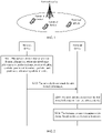
- FIG. 6 is a schematic structural diagram of a network device 60 according to an implementation of this application.
- the network device 60 includes a processing module 601 and a sending module 602.
- the network device 60 further includes a receiving module 603.
- the processing module 601 is configured to determine slot format information, where the slot format information is used to indicate position of uplink symbols, position of downlink symbols, and position of unknown symbols in a slot.
- the sending module 602 is configured to send the slot format information.
- the sending module 602 is specifically configured to:
- the receiving module 603 is configured to receive latency requirement information of at least one terminal device from the at least one terminal device before the slot format information is determined.
- the information transmission device provided in this embodiment may be configured to perform the technical solution performed by the network device or the chip of the network device in the foregoing method implementations.
- An implementation principle and a technical effect of the information transmission device are similar to the network device or the chip of the network device in the foregoing method implementations.
- the processing module 601 may be further implemented as a processor, and the processor may execute an executable instruction stored in a memory, to implement the foregoing method. Details may be shown in FIG. 7 .
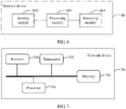
- FIG. 7 is a structural diagram of hardware of a network device 70 according to an implementation of this application.
- the network device 70 includes a processor 701 and a memory 702.
- the memory 702 is configured to store a computer program, and the memory may be further a flash (flash).
- the processor 701 is configured to execute an executable instruction stored in the memory 702, to implement steps performed by the network device in the foregoing information transmission method. For details, refer to related descriptions in the foregoing method implementations.
- the memory 702 may be independent, or may be integrated with the processor 701.
- the network device 70 further includes a transmitter 703 and a receiver 704.
- the processor 701 is configured to determine slot format information, where the slot format information is used to indicate position of uplink symbols, position of downlink symbols, and position of unknown symbols in a slot; and the transmitter 703 is configured to send the slot format information.
- the transmitter 703 is specifically configured to:
- the receiver 704 is configured to receive latency requirement information of at least one terminal device from the at least one terminal device before the slot format information is determined.
- the network device provided in this embodiment may be configured to perform the technical solution performed by the network device in the foregoing method implementations.
- An implementation principle and a technical effect of the network device are similar to the network device in the foregoing method implementations, and reference may be made to the corresponding description in the method implementations. Details are not described herein.
- FIG. 8 is a schematic structural diagram of a terminal device according to an implementation of this application.
- the terminal device 80 includes a receiving module 801, a processing module 802, and a sending module 803.
- the receiving module 801 is configured to receive slot format information from a network device, where the slot format information is used to indicate position of uplink symbols, position of downlink symbols, and position of unknown symbols in a slot.
- the processing module 802 is configured to determine a slot format based on the slot format information.
- the receiving module 801 is specifically configured to:
- the sending module 803 is configured to send latency requirement information to the network device before the slot format information is received from the network device.
- the information transmission device provided in this embodiment may be configured to perform the technical solution performed by the terminal device or the chip of the terminal device in the foregoing method implementations.
- An implementation principle and a technical effect of the information transmission device are similar to the terminal device or the chip of the terminal device in the foregoing method implementations.
- the processing module 802 may be further implemented as a processor, and the processor may execute an executable instruction stored in a memory, to implement the foregoing method. Details may be shown in FIG. 9 .
- FIG. 9 is a structural diagram of hardware of a terminal device 90 according to an implementation of this application. As shown in FIG. 9 , the terminal device 90 includes a processor 901 and a memory 902.
- the memory 902 is configured to store a computer program, and the memory may be further a flash (flash).
- the processor 901 is configured to execute an executable instruction stored in the memory 902, to implement steps performed by the terminal device in the foregoing information transmission method. For details, refer to related descriptions in the foregoing method implementations.
- the memory 902 may be independent, or may be integrated with the processor 901.
- the terminal device 90 further includes a transmitter 903 and a receiver 904.
- the receiver 904 is configured to receive slot format information from a network device, where the slot format information is used to indicate position of uplink symbols, position of downlink symbols, and position of unknown symbols in a slot.
- the processor 901 is configured to determine a slot format based on the slot format information.
- the receiver 904 is specifically configured to:
- the transmitter 903 is configured to send latency requirement information to the network device before the slot format information is received from the network device.
- the terminal device provided in this embodiment may be configured to perform the technical solution performed by the terminal device in the foregoing method implementations.
- An implementation principle and a technical effect of the terminal device are similar to the terminal device in the foregoing method implementations, and reference may be made to the corresponding description in the method implementations. Details are not described herein.
- the slot format information is a slot format index
- the slot format index is used to indicate a row in a slot format information table.
- Each row in the slot format information table is used to indicate position of uplink symbols, position of downlink symbols, and position of unknown symbols in one or more slots.
- the slot format information corresponds to the slot format information table
- the slot format information table includes a first slot format
- the first slot format satisfies: the first to eighth symbols start with one or more downlink symbols, and end with one or more uplink symbols, there is at least one unknown symbol between the downlink symbol and the uplink symbol, and the ninth to fourteenth symbols are downlink symbols.
- the first slot format is represented as DDXXXUUUDDDDDD, D represents a downlink symbol, U represents an uplink symbol, and X represents an unknown symbol.
- the slot format information table is prestored.
- the ninth to fourteenth symbols in the slot are downlink symbols.
- the first symbol is a downlink symbol
- the second symbol is an unknown symbol
- the third symbol is an uplink symbol
- the fourth symbol is a downlink symbol
- the fifth symbol is an unknown symbol
- the sixth symbol is an uplink symbol
- the first symbol is a downlink symbol
- the second symbol is a downlink symbol
- the third symbol is an unknown symbol
- the fourth symbol is an uplink symbol
- the fifth symbol is a downlink symbol
- the sixth symbol is an unknown symbol
- a first subcarrier is used to transmit uplink information carried on the uplink symbol and downlink information carried on the downlink symbol; and a subcarrier spacing of the first subcarrier is greater than or equal to a subcarrier spacing of a second subcarrier, and the second subcarrier is used to transmit a synchronization block sent by the network device.
- the unknown symbol is a flexible symbol.
- a computer storage medium is further provided.
- the storage medium includes an instruction, and when the instruction is executed by a computer, the computer is enabled to implement the forgoing information transmission method performed by the network device.
- a computer storage medium is further provided.
- the storage medium includes an instruction, and when the instruction is executed by a computer, the computer is enabled to implement the foregoing information transmission method performed by the terminal device.
- a chip is further provided, including a memory and a processor.
- the memory is configured to store a program instruction.
- the processor is configured to invoke the program instruction stored in the memory to implement the foregoing information transmission method performed by the network device.
- a chip is further provided, including a memory and a processor.
- the memory is configured to store a program instruction.
- the processor is configured to invoke the program instruction stored in the memory to implement the foregoing information transmission method performed by the terminal device.
- a program product is further provided.
- the program product includes a computer program, the computer program is stored in a readable storage medium, and at least one processor of a network device may read the computer program from the readable storage medium.
- the at least one processor executes the computer program, so that the network device performs the foregoing information transmission method.
- a program product is further provided.
- the program product includes a computer program, the computer program is stored in a readable storage medium, and at least one processor of a terminal device may read the computer program from the readable storage medium.
- the at least one processor executes the computer program, so that the terminal device performs the foregoing information transmission method.
- a communications apparatus including a processor and a communications interface.
- the processor is configured to support the communications apparatus in performing the information transmission method performed by the network device, and the communications interface is configured to support communication between the communications apparatus and another communications device.
- a communications apparatus including a processor and a communications interface.
- the processor is configured to support the communications apparatus in performing the information transmission method performed by the terminal device, and the communications interface is configured to support communication between the communications apparatus and another communications device.
- the processor may be a central processing unit (Central Processing Unit, CPU for short), or may be another general-purpose processor, a digital signal processor (Digital Signal Processor, DSP for short), an application-specific integrated circuit (Application-Specific Integrated Circuit, ASIC for short), or the like.
- the general-purpose processor may be a microprocessor, or the processor may be alternatively any conventional processor or the like.
- the steps of the methods disclosed with reference to this application may be directly implemented by a hardware processor, or may be implemented by a combination of hardware and a software module in the processor.
- the foregoing memory includes a read-only memory (read-only memory, ROM for short), a RAM, a flash memory, a hard disk, a solid-state drive, a magnetic tape (magnetic tape), a floppy disk (floppy disk), an optical disc (optical disc), and any combination thereof.
Landscapes
- Engineering & Computer Science (AREA)
- Signal Processing (AREA)
- Computer Networks & Wireless Communication (AREA)
- Quality & Reliability (AREA)
- Physics & Mathematics (AREA)
- Mathematical Physics (AREA)
- Mobile Radio Communication Systems (AREA)
- Communication Control (AREA)
Claims (11)
- Informationsübertragungsverfahren, das von einem Netzwerkgerät durchgeführt wird, das mit einem Endgerät über erste Unterträger und zweite Unterträger kommuniziert, wobei ein Unterträgerabstand der ersten Unterträger größer ist als ein Unterträgerabstand der zweiten Unterträger, wobei das Verfahren Folgendes umfasst:Bestimmen (S201) eines Slot-Format-Index der ersten Unterträger, wobei der Slot-Format-Index eine Zeile in einer Slot-Format-Informationstabelle anzeigt, die Zeile ein Slot-Format DDXXXUUUDDDDDD anzeigt, wobei D ein Downlink-Symbol, U ein Uplink-Symbol und X ein unbekanntes Symbol darstellt und jede Zeile in der Slot-Format-Informationstabelle die Position von Uplink-Symbolen, die Position von Downlink-Symbolen und die Position von unbekannten Symbolen in einem oder mehreren Slots anzeigt; undSenden (S202) des Slot-Format-Index an ein Endgerät, um es dem Endgerät zu ermöglichen, das Slot-Format zu bestimmen;Durchführen einer Frequenzmultiplexübertragung mit dem Endgerät unter Verwendung eines Trägers der zweiten Unterträger für die Übertragung eines Synchronisationsblocks und eines Trägers der ersten Unterträger für einen Uplink- oder Downlink-Informationsblock des Endgerätes.
- Verfahren gemäß Anspruch 1, wobei das Senden, durch das Netzwerkgerät, des Slot-Format-Index an das Endgerät Folgendes umfasst:Senden von Downlink-Steuerinformationen, wobei die Downlink-Steuerinformationen den Slot-Format-Index enthalten; oderSenden einer Signalisierung der höheren Schicht, wobei die Signalisierung der höheren Schicht den Slot-Format-Index trägt.
- Verfahren gemäß Anspruch 1 oder 2, wobei ein unbekanntes Symbol ein flexibles Symbol ist.
- Verfahren gemäß einem der Ansprüche 1 bis 3, wobei die Slot-Format-Tabelle vorgespeichert wird.
- Informationsübertragungsverfahren, das von einem Endgerät durchgeführt wird, das mit einem Netzwerkgerät über erste Unterträger und zweite Unterträger kommuniziert, wobei ein Unterträgerabstand der ersten Unterträger größer ist als ein Unterträgerabstand der zweiten Unterträger, wobei das Verfahren Folgendes umfasst:Empfangen (203) eines Slot-Format-Index der ersten Unterträger von einem Netzwerkgerät, wobei der Slot-Format-Index eine Zeile in einer Slot-Format-Informationstabelle anzeigt, die Zeile ein Slot-Format DDXXXUUUDDDDDD anzeigt, wobei D ein Downlink-Symbol, U ein Uplink-Symbol und X ein unbekanntes Symbol darstellt, jede Zeile in der Slot-Format-Informationstabelle die Position von Uplink-Symbolen, die Position von Downlink-Symbolen und die Position von unbekannten Symbolen in einem oder mehreren Slots anzeigt; undBestimmen (S204) des Slot-Formats auf der Basis des Slot-Format-Index;Durchführen einer Frequenzmultiplexübertragung mit dem Netzwerkgerät unter Verwendung eines Trägers der zweiten Unterträger für den Empfang eines Synchronisationsblocks und eines Trägers der ersten Unterträger für einen Uplink- oder Downlink-Informationsblock des Endgerätes.
- Verfahren gemäß Anspruch 5, wobei das Empfangen, durch ein Endgerät, eines Slot-Format-Index von einem Netzwerkgerät Folgendes umfasst:Empfangen von Downlink-Steuerinformationen von dem Netzwerkgerät, wobei die Downlink-Steuerinformationen den Slot-Format-Index tragen; oderEmpfangen einer Signalisierung der höheren Schicht von dem Netzwerkgerät, wobei die Signalisierung der höheren Schicht den Slot-Format-Index trägt.
- Verfahren gemäß Anspruch 5 oder 6, wobei ein unbekanntes Symbol ein flexibles Symbol ist.
- Verfahren gemäß einem der Ansprüche 5 bis 7, wobei die Slot-Format-Tabelle vorgespeichert wird.
- Vorrichtung zur Informationsübertragung, die Mittel zur Implementierung des Verfahrens gemäß einem der Ansprüche 1 bis 4 umfasst.
- Vorrichtung zur Informationsübertragung, die Mittel zur Implementierung des Verfahrens gemäß einem der Ansprüche 5 bis 8 umfasst.
- Computerspeichermedium, wobei das Speichermedium eine Anweisung umfasst, und wenn die Anweisung von einem Computer ausgeführt wird, der Computer in die Lage versetzt wird, das Informationsübertragungsverfahren gemäß einem der Ansprüche 1 bis 4 oder gemäß einem der Ansprüche 5 bis 8 durchzuführen.
Applications Claiming Priority (3)
| Application Number | Priority Date | Filing Date | Title |
|---|---|---|---|
| CN201711147522 | 2017-11-17 | ||
| CN201810032105.3A CN109802816B (zh) | 2017-11-17 | 2018-01-12 | 信息传输方法及设备 |
| PCT/CN2018/113090 WO2019096009A1 (zh) | 2017-11-17 | 2018-10-31 | 信息传输方法及设备 |
Publications (3)
| Publication Number | Publication Date |
|---|---|
| EP3703298A1 EP3703298A1 (de) | 2020-09-02 |
| EP3703298A4 EP3703298A4 (de) | 2020-12-16 |
| EP3703298B1 true EP3703298B1 (de) | 2022-09-07 |
Family
ID=66556154
Family Applications (1)
| Application Number | Title | Priority Date | Filing Date |
|---|---|---|---|
| EP18879742.7A Active EP3703298B1 (de) | 2017-11-17 | 2018-10-31 | Informationsübertragungsverfahren und -vorrichtung |
Country Status (8)
| Country | Link |
|---|---|
| US (1) | US11239938B2 (de) |
| EP (1) | EP3703298B1 (de) |
| JP (1) | JP6974612B2 (de) |
| KR (1) | KR102444600B1 (de) |
| CN (2) | CN110519031B (de) |
| AU (1) | AU2018368980B2 (de) |
| BR (1) | BR112020009588A2 (de) |
| RU (1) | RU2768790C2 (de) |
Families Citing this family (10)
| Publication number | Priority date | Publication date | Assignee | Title |
|---|---|---|---|---|
| CN112135270B (zh) | 2019-06-25 | 2021-09-24 | 上海朗帛通信技术有限公司 | 一种被用于无线通信的节点中的方法和装置 |
| US20220256534A1 (en) * | 2019-07-12 | 2022-08-11 | Lenovo (Beijing) Limited | Method and apparatus for indicating tdd uplink-downlink configuration |
| CN110519857B (zh) * | 2019-08-16 | 2021-09-28 | 中国信息通信研究院 | 一种数据发送结构指示方法和设备 |
| US11743865B2 (en) * | 2020-06-19 | 2023-08-29 | Qualcomm Incorporated | Scheduled entity behavior in full-duplex slot format |
| CN111934836B (zh) * | 2020-08-06 | 2024-10-18 | 中兴通讯股份有限公司 | 数据传输方法、装置、设备和存储介质 |
| CN113747379B (zh) * | 2021-07-09 | 2022-08-30 | 重庆御芯微信息技术有限公司 | 一种广域无线物联网通信的短消息数据传输方法 |
| CN115885559A (zh) * | 2021-07-28 | 2023-03-31 | 北京小米移动软件有限公司 | 一种时隙结构的配置方法及其装置 |
| WO2024016347A1 (zh) * | 2022-07-22 | 2024-01-25 | Oppo广东移动通信有限公司 | 通信方法及通信装置 |
| WO2024063605A1 (ko) * | 2022-09-22 | 2024-03-28 | 한국전자통신연구원 | 동일 대역 전이중 통신에서 무선 자원의 할당 방법 및 장치 |
| CN118741694A (zh) * | 2023-03-28 | 2024-10-01 | 北京紫光展锐通信技术有限公司 | 通信方法及装置 |
Family Cites Families (16)
| Publication number | Priority date | Publication date | Assignee | Title |
|---|---|---|---|---|
| US8098645B2 (en) * | 2008-02-21 | 2012-01-17 | General Dynamics C4 Systems, Inc. | Random access slot selection in a communications system |
| CN103209489B (zh) * | 2012-01-17 | 2017-04-12 | 华为技术有限公司 | 数据的传输方法、基站和用户设备 |
| KR20160060744A (ko) | 2013-09-26 | 2016-05-30 | 후아웨이 테크놀러지 컴퍼니 리미티드 | 업링크 정보 전송 방법 및 장치, 수신 방법 및 장치, 그리고 통신 시스템 |
| CN105099632B (zh) * | 2014-04-23 | 2019-12-13 | 北京三星通信技术研究有限公司 | 一种上行探测参考信号传输的方法和设备 |
| CN105991251B (zh) | 2015-02-17 | 2019-06-21 | 华为技术有限公司 | 信息传输的方法、用户设备和基站 |
| CN106685603B (zh) * | 2015-11-11 | 2019-11-05 | 华为技术有限公司 | Tdd系统信息传输的方法和装置 |
| CN106888077B (zh) * | 2015-12-15 | 2020-08-11 | 中兴通讯股份有限公司 | 信息的传输方法及装置 |
| WO2017111808A1 (en) * | 2015-12-24 | 2017-06-29 | Intel IP Corporation | Collision avoidance technology for an enhanced physical uplink control channel |
| CN106982465B (zh) | 2016-01-15 | 2021-02-23 | 华为技术有限公司 | 一种无线帧的传输方法以及无线网络设备 |
| CN107204951A (zh) | 2016-03-17 | 2017-09-26 | 电信科学技术研究院 | 一种通信系统中传输信息的方法及装置 |
| CN107295652B (zh) | 2016-03-31 | 2023-07-18 | 华为技术有限公司 | 信息的传输方法及设备 |
| CN107306171A (zh) * | 2016-04-19 | 2017-10-31 | 华为技术有限公司 | 数据传输的方法、设备和系统 |
| CN106465392B (zh) | 2016-08-17 | 2019-12-06 | 北京小米移动软件有限公司 | 通信方法及装置 |
| SG11201810581SA (en) * | 2017-03-24 | 2018-12-28 | Lg Electronics Inc | Method of transmitting or receiving signals in wireless communication system and apparatus therefor |
| EP4120590B1 (de) * | 2017-03-24 | 2024-09-11 | Wilus Institute of Standards and Technology Inc. | Verfahren, vorrichtung und system zum senden und empfangen eines steuerkanals eines drahtloskommunikationssystems |
| CN108809614B9 (zh) * | 2017-11-17 | 2019-09-06 | 华为技术有限公司 | 信息传输方法及设备 |
-
2018
- 2018-01-12 CN CN201910764826.8A patent/CN110519031B/zh active Active
- 2018-01-12 CN CN201810032105.3A patent/CN109802816B/zh active Active
- 2018-10-31 AU AU2018368980A patent/AU2018368980B2/en active Active
- 2018-10-31 RU RU2020119775A patent/RU2768790C2/ru active
- 2018-10-31 EP EP18879742.7A patent/EP3703298B1/de active Active
- 2018-10-31 BR BR112020009588-5A patent/BR112020009588A2/pt unknown
- 2018-10-31 JP JP2020526907A patent/JP6974612B2/ja active Active
- 2018-10-31 KR KR1020207015188A patent/KR102444600B1/ko active IP Right Grant
-
2020
- 2020-05-13 US US15/931,571 patent/US11239938B2/en active Active
Also Published As
| Publication number | Publication date |
|---|---|
| US20200322080A1 (en) | 2020-10-08 |
| RU2020119775A3 (de) | 2021-12-17 |
| RU2768790C2 (ru) | 2022-03-24 |
| AU2018368980A1 (en) | 2020-05-21 |
| US11239938B2 (en) | 2022-02-01 |
| CN110519031B (zh) | 2020-12-25 |
| CN109802816A (zh) | 2019-05-24 |
| BR112020009588A2 (pt) | 2020-10-13 |
| JP2021503797A (ja) | 2021-02-12 |
| CN110519031A (zh) | 2019-11-29 |
| CN109802816B (zh) | 2021-01-29 |
| KR20200071126A (ko) | 2020-06-18 |
| KR102444600B1 (ko) | 2022-09-16 |
| EP3703298A4 (de) | 2020-12-16 |
| RU2020119775A (ru) | 2021-12-17 |
| EP3703298A1 (de) | 2020-09-02 |
| JP6974612B2 (ja) | 2021-12-01 |
| AU2018368980B2 (en) | 2021-06-03 |
Similar Documents
| Publication | Publication Date | Title |
|---|---|---|
| EP3703298B1 (de) | Informationsübertragungsverfahren und -vorrichtung | |
| US11483820B2 (en) | Data transmission method, terminal device, and network device | |
| US20190082453A1 (en) | Downlink Control Information Transmission Method and Apparatus | |
| EP3094030B1 (de) | Bestätigungsübertragungsverfahren und vorrichtung in einem drahtloskommunikationssystem | |
| WO2019096009A1 (zh) | 信息传输方法及设备 | |
| CA3030456C (en) | Method and terminal device for transmitting data | |
| EP3952540A1 (de) | Kommunikationsverfahren und kommunikationsvorrichtung | |
| US20180338306A1 (en) | Uplink information transmission method and apparatus | |
| EP3761701B1 (de) | Verfahren zur ressourcenbestimmung, anzeigeverfahren und vorrichtung | |
| CN115767750A (zh) | 用于下行链路控制物理结构的方法和设备 | |
| CN109218002B (zh) | 在频宽部分中执行数据传输的装置及方法 | |
| CN110035528A (zh) | 一种通信方法、装置以及系统 | |
| EP3629650B1 (de) | Verfahren und vorrichtung zur übertragung von informationen und zur bestimmung von informationen | |
| EP3487230B1 (de) | Senden und empfangen von uplink-scheduling-informationen | |
| CN107251501B (zh) | 一种信息的发送和接收方法、用户设备及基站 | |
| WO2021159320A1 (zh) | 通信方法及装置 | |
| EP3399689A1 (de) | Datenübertragungsverfahren, endgerätevorrichtung und netzwerkeinrichtung | |
| EP3606279A1 (de) | Verfahren und vorrichtung zur anzeige der unterrahmenkonfiguration | |
| CN117242797A (zh) | 用于类型1 harq-ack码本确定的方法及装置 | |
| CN116508366A (zh) | 用于由一个dci格式调度的多个传输的方法及设备 |
Legal Events
| Date | Code | Title | Description |
|---|---|---|---|
| STAA | Information on the status of an ep patent application or granted ep patent |
Free format text: STATUS: THE INTERNATIONAL PUBLICATION HAS BEEN MADE |
|
| PUAI | Public reference made under article 153(3) epc to a published international application that has entered the european phase |
Free format text: ORIGINAL CODE: 0009012 |
|
| STAA | Information on the status of an ep patent application or granted ep patent |
Free format text: STATUS: REQUEST FOR EXAMINATION WAS MADE |
|
| 17P | Request for examination filed |
Effective date: 20200525 |
|
| AK | Designated contracting states |
Kind code of ref document: A1 Designated state(s): AL AT BE BG CH CY CZ DE DK EE ES FI FR GB GR HR HU IE IS IT LI LT LU LV MC MK MT NL NO PL PT RO RS SE SI SK SM TR |
|
| AX | Request for extension of the european patent |
Extension state: BA ME |
|
| A4 | Supplementary search report drawn up and despatched |
Effective date: 20201113 |
|
| RIC1 | Information provided on ipc code assigned before grant |
Ipc: H04L 5/00 20060101AFI20201109BHEP Ipc: H04L 27/26 20060101ALI20201109BHEP Ipc: H04W 72/04 20090101ALI20201109BHEP |
|
| DAV | Request for validation of the european patent (deleted) | ||
| DAX | Request for extension of the european patent (deleted) | ||
| STAA | Information on the status of an ep patent application or granted ep patent |
Free format text: STATUS: EXAMINATION IS IN PROGRESS |
|
| 17Q | First examination report despatched |
Effective date: 20210910 |
|
| GRAP | Despatch of communication of intention to grant a patent |
Free format text: ORIGINAL CODE: EPIDOSNIGR1 |
|
| STAA | Information on the status of an ep patent application or granted ep patent |
Free format text: STATUS: GRANT OF PATENT IS INTENDED |
|
| INTG | Intention to grant announced |
Effective date: 20220426 |
|
| GRAS | Grant fee paid |
Free format text: ORIGINAL CODE: EPIDOSNIGR3 |
|
| GRAA | (expected) grant |
Free format text: ORIGINAL CODE: 0009210 |
|
| STAA | Information on the status of an ep patent application or granted ep patent |
Free format text: STATUS: THE PATENT HAS BEEN GRANTED |
|
| AK | Designated contracting states |
Kind code of ref document: B1 Designated state(s): AL AT BE BG CH CY CZ DE DK EE ES FI FR GB GR HR HU IE IS IT LI LT LU LV MC MK MT NL NO PL PT RO RS SE SI SK SM TR |
|
| REG | Reference to a national code |
Ref country code: GB Ref legal event code: FG4D |
|
| REG | Reference to a national code |
Ref country code: CH Ref legal event code: EP Ref country code: AT Ref legal event code: REF Ref document number: 1517940 Country of ref document: AT Kind code of ref document: T Effective date: 20220915 |
|
| REG | Reference to a national code |
Ref country code: DE Ref legal event code: R096 Ref document number: 602018040500 Country of ref document: DE |
|
| REG | Reference to a national code |
Ref country code: IE Ref legal event code: FG4D |
|
| REG | Reference to a national code |
Ref country code: LT Ref legal event code: MG9D |
|
| REG | Reference to a national code |
Ref country code: NL Ref legal event code: MP Effective date: 20220907 |
|
| PG25 | Lapsed in a contracting state [announced via postgrant information from national office to epo] |
Ref country code: SE Free format text: LAPSE BECAUSE OF FAILURE TO SUBMIT A TRANSLATION OF THE DESCRIPTION OR TO PAY THE FEE WITHIN THE PRESCRIBED TIME-LIMIT Effective date: 20220907 Ref country code: RS Free format text: LAPSE BECAUSE OF FAILURE TO SUBMIT A TRANSLATION OF THE DESCRIPTION OR TO PAY THE FEE WITHIN THE PRESCRIBED TIME-LIMIT Effective date: 20220907 Ref country code: NO Free format text: LAPSE BECAUSE OF FAILURE TO SUBMIT A TRANSLATION OF THE DESCRIPTION OR TO PAY THE FEE WITHIN THE PRESCRIBED TIME-LIMIT Effective date: 20221207 Ref country code: LV Free format text: LAPSE BECAUSE OF FAILURE TO SUBMIT A TRANSLATION OF THE DESCRIPTION OR TO PAY THE FEE WITHIN THE PRESCRIBED TIME-LIMIT Effective date: 20220907 Ref country code: LT Free format text: LAPSE BECAUSE OF FAILURE TO SUBMIT A TRANSLATION OF THE DESCRIPTION OR TO PAY THE FEE WITHIN THE PRESCRIBED TIME-LIMIT Effective date: 20220907 Ref country code: FI Free format text: LAPSE BECAUSE OF FAILURE TO SUBMIT A TRANSLATION OF THE DESCRIPTION OR TO PAY THE FEE WITHIN THE PRESCRIBED TIME-LIMIT Effective date: 20220907 |
|
| REG | Reference to a national code |
Ref country code: AT Ref legal event code: MK05 Ref document number: 1517940 Country of ref document: AT Kind code of ref document: T Effective date: 20220907 |
|
| PG25 | Lapsed in a contracting state [announced via postgrant information from national office to epo] |
Ref country code: HR Free format text: LAPSE BECAUSE OF FAILURE TO SUBMIT A TRANSLATION OF THE DESCRIPTION OR TO PAY THE FEE WITHIN THE PRESCRIBED TIME-LIMIT Effective date: 20220907 Ref country code: GR Free format text: LAPSE BECAUSE OF FAILURE TO SUBMIT A TRANSLATION OF THE DESCRIPTION OR TO PAY THE FEE WITHIN THE PRESCRIBED TIME-LIMIT Effective date: 20221208 |
|
| PG25 | Lapsed in a contracting state [announced via postgrant information from national office to epo] |
Ref country code: SM Free format text: LAPSE BECAUSE OF FAILURE TO SUBMIT A TRANSLATION OF THE DESCRIPTION OR TO PAY THE FEE WITHIN THE PRESCRIBED TIME-LIMIT Effective date: 20220907 Ref country code: RO Free format text: LAPSE BECAUSE OF FAILURE TO SUBMIT A TRANSLATION OF THE DESCRIPTION OR TO PAY THE FEE WITHIN THE PRESCRIBED TIME-LIMIT Effective date: 20220907 Ref country code: PT Free format text: LAPSE BECAUSE OF FAILURE TO SUBMIT A TRANSLATION OF THE DESCRIPTION OR TO PAY THE FEE WITHIN THE PRESCRIBED TIME-LIMIT Effective date: 20230109 Ref country code: ES Free format text: LAPSE BECAUSE OF FAILURE TO SUBMIT A TRANSLATION OF THE DESCRIPTION OR TO PAY THE FEE WITHIN THE PRESCRIBED TIME-LIMIT Effective date: 20220907 Ref country code: CZ Free format text: LAPSE BECAUSE OF FAILURE TO SUBMIT A TRANSLATION OF THE DESCRIPTION OR TO PAY THE FEE WITHIN THE PRESCRIBED TIME-LIMIT Effective date: 20220907 Ref country code: AT Free format text: LAPSE BECAUSE OF FAILURE TO SUBMIT A TRANSLATION OF THE DESCRIPTION OR TO PAY THE FEE WITHIN THE PRESCRIBED TIME-LIMIT Effective date: 20220907 |
|
| PG25 | Lapsed in a contracting state [announced via postgrant information from national office to epo] |
Ref country code: SK Free format text: LAPSE BECAUSE OF FAILURE TO SUBMIT A TRANSLATION OF THE DESCRIPTION OR TO PAY THE FEE WITHIN THE PRESCRIBED TIME-LIMIT Effective date: 20220907 Ref country code: PL Free format text: LAPSE BECAUSE OF FAILURE TO SUBMIT A TRANSLATION OF THE DESCRIPTION OR TO PAY THE FEE WITHIN THE PRESCRIBED TIME-LIMIT Effective date: 20220907 Ref country code: IS Free format text: LAPSE BECAUSE OF FAILURE TO SUBMIT A TRANSLATION OF THE DESCRIPTION OR TO PAY THE FEE WITHIN THE PRESCRIBED TIME-LIMIT Effective date: 20230107 Ref country code: EE Free format text: LAPSE BECAUSE OF FAILURE TO SUBMIT A TRANSLATION OF THE DESCRIPTION OR TO PAY THE FEE WITHIN THE PRESCRIBED TIME-LIMIT Effective date: 20220907 |
|
| REG | Reference to a national code |
Ref country code: CH Ref legal event code: PL |
|
| REG | Reference to a national code |
Ref country code: DE Ref legal event code: R097 Ref document number: 602018040500 Country of ref document: DE |
|
| REG | Reference to a national code |
Ref country code: BE Ref legal event code: MM Effective date: 20221031 |
|
| P01 | Opt-out of the competence of the unified patent court (upc) registered |
Effective date: 20230524 |
|
| PG25 | Lapsed in a contracting state [announced via postgrant information from national office to epo] |
Ref country code: NL Free format text: LAPSE BECAUSE OF FAILURE TO SUBMIT A TRANSLATION OF THE DESCRIPTION OR TO PAY THE FEE WITHIN THE PRESCRIBED TIME-LIMIT Effective date: 20220907 Ref country code: MC Free format text: LAPSE BECAUSE OF FAILURE TO SUBMIT A TRANSLATION OF THE DESCRIPTION OR TO PAY THE FEE WITHIN THE PRESCRIBED TIME-LIMIT Effective date: 20220907 Ref country code: LU Free format text: LAPSE BECAUSE OF NON-PAYMENT OF DUE FEES Effective date: 20221031 Ref country code: AL Free format text: LAPSE BECAUSE OF FAILURE TO SUBMIT A TRANSLATION OF THE DESCRIPTION OR TO PAY THE FEE WITHIN THE PRESCRIBED TIME-LIMIT Effective date: 20220907 |
|
| PLBE | No opposition filed within time limit |
Free format text: ORIGINAL CODE: 0009261 |
|
| STAA | Information on the status of an ep patent application or granted ep patent |
Free format text: STATUS: NO OPPOSITION FILED WITHIN TIME LIMIT |
|
| PG25 | Lapsed in a contracting state [announced via postgrant information from national office to epo] |
Ref country code: DK Free format text: LAPSE BECAUSE OF FAILURE TO SUBMIT A TRANSLATION OF THE DESCRIPTION OR TO PAY THE FEE WITHIN THE PRESCRIBED TIME-LIMIT Effective date: 20220907 Ref country code: CH Free format text: LAPSE BECAUSE OF NON-PAYMENT OF DUE FEES Effective date: 20221031 Ref country code: LI Free format text: LAPSE BECAUSE OF NON-PAYMENT OF DUE FEES Effective date: 20221031 |
|
| 26N | No opposition filed |
Effective date: 20230608 |
|
| PG25 | Lapsed in a contracting state [announced via postgrant information from national office to epo] |
Ref country code: SI Free format text: LAPSE BECAUSE OF FAILURE TO SUBMIT A TRANSLATION OF THE DESCRIPTION OR TO PAY THE FEE WITHIN THE PRESCRIBED TIME-LIMIT Effective date: 20220907 |
|
| PG25 | Lapsed in a contracting state [announced via postgrant information from national office to epo] |
Ref country code: BE Free format text: LAPSE BECAUSE OF NON-PAYMENT OF DUE FEES Effective date: 20221031 |
|
| PG25 | Lapsed in a contracting state [announced via postgrant information from national office to epo] |
Ref country code: IE Free format text: LAPSE BECAUSE OF NON-PAYMENT OF DUE FEES Effective date: 20221031 |
|
| PG25 | Lapsed in a contracting state [announced via postgrant information from national office to epo] |
Ref country code: FR Free format text: LAPSE BECAUSE OF NON-PAYMENT OF DUE FEES Effective date: 20221107 |
|
| PGFP | Annual fee paid to national office [announced via postgrant information from national office to epo] |
Ref country code: DE Payment date: 20230906 Year of fee payment: 6 |
|
| PG25 | Lapsed in a contracting state [announced via postgrant information from national office to epo] |
Ref country code: CY Free format text: LAPSE BECAUSE OF FAILURE TO SUBMIT A TRANSLATION OF THE DESCRIPTION OR TO PAY THE FEE WITHIN THE PRESCRIBED TIME-LIMIT Effective date: 20220907 |
|
| PG25 | Lapsed in a contracting state [announced via postgrant information from national office to epo] |
Ref country code: MK Free format text: LAPSE BECAUSE OF FAILURE TO SUBMIT A TRANSLATION OF THE DESCRIPTION OR TO PAY THE FEE WITHIN THE PRESCRIBED TIME-LIMIT Effective date: 20220907 Ref country code: IT Free format text: LAPSE BECAUSE OF FAILURE TO SUBMIT A TRANSLATION OF THE DESCRIPTION OR TO PAY THE FEE WITHIN THE PRESCRIBED TIME-LIMIT Effective date: 20220907 Ref country code: HU Free format text: LAPSE BECAUSE OF FAILURE TO SUBMIT A TRANSLATION OF THE DESCRIPTION OR TO PAY THE FEE WITHIN THE PRESCRIBED TIME-LIMIT; INVALID AB INITIO Effective date: 20181031 |
|
| PG25 | Lapsed in a contracting state [announced via postgrant information from national office to epo] |
Ref country code: TR Free format text: LAPSE BECAUSE OF FAILURE TO SUBMIT A TRANSLATION OF THE DESCRIPTION OR TO PAY THE FEE WITHIN THE PRESCRIBED TIME-LIMIT Effective date: 20220907 |
|
| PG25 | Lapsed in a contracting state [announced via postgrant information from national office to epo] |
Ref country code: BG Free format text: LAPSE BECAUSE OF FAILURE TO SUBMIT A TRANSLATION OF THE DESCRIPTION OR TO PAY THE FEE WITHIN THE PRESCRIBED TIME-LIMIT Effective date: 20220907 |
|
| PG25 | Lapsed in a contracting state [announced via postgrant information from national office to epo] |
Ref country code: MT Free format text: LAPSE BECAUSE OF FAILURE TO SUBMIT A TRANSLATION OF THE DESCRIPTION OR TO PAY THE FEE WITHIN THE PRESCRIBED TIME-LIMIT Effective date: 20220907 |
|
| PGFP | Annual fee paid to national office [announced via postgrant information from national office to epo] |
Ref country code: GB Payment date: 20240912 Year of fee payment: 7 |