EP3869468A1 - Augmented reality system using visual object recognition and stored geometry to create and render virtual objects - Google Patents
Augmented reality system using visual object recognition and stored geometry to create and render virtual objects Download PDFInfo
- Publication number
- EP3869468A1 EP3869468A1 EP21155641.0A EP21155641A EP3869468A1 EP 3869468 A1 EP3869468 A1 EP 3869468A1 EP 21155641 A EP21155641 A EP 21155641A EP 3869468 A1 EP3869468 A1 EP 3869468A1
- Authority
- EP
- European Patent Office
- Prior art keywords
- dimensional geometry
- virtual
- point
- geometry
- virtual object
- Prior art date
- Legal status (The legal status is an assumption and is not a legal conclusion. Google has not performed a legal analysis and makes no representation as to the accuracy of the status listed.)
- Withdrawn
Links
Images


Classifications
-
- G—PHYSICS
- G06—COMPUTING OR CALCULATING; COUNTING
- G06T—IMAGE DATA PROCESSING OR GENERATION, IN GENERAL
- G06T7/00—Image analysis
- G06T7/70—Determining position or orientation of objects or cameras
-
- G—PHYSICS
- G06—COMPUTING OR CALCULATING; COUNTING
- G06T—IMAGE DATA PROCESSING OR GENERATION, IN GENERAL
- G06T19/00—Manipulating 3D models or images for computer graphics
- G06T19/006—Mixed reality
-
- G—PHYSICS
- G06—COMPUTING OR CALCULATING; COUNTING
- G06V—IMAGE OR VIDEO RECOGNITION OR UNDERSTANDING
- G06V20/00—Scenes; Scene-specific elements
- G06V20/20—Scenes; Scene-specific elements in augmented reality scenes
-
- G—PHYSICS
- G06—COMPUTING OR CALCULATING; COUNTING
- G06T—IMAGE DATA PROCESSING OR GENERATION, IN GENERAL
- G06T2200/00—Indexing scheme for image data processing or generation, in general
- G06T2200/24—Indexing scheme for image data processing or generation, in general involving graphical user interfaces [GUIs]
-
- G—PHYSICS
- G06—COMPUTING OR CALCULATING; COUNTING
- G06T—IMAGE DATA PROCESSING OR GENERATION, IN GENERAL
- G06T2207/00—Indexing scheme for image analysis or image enhancement
- G06T2207/10—Image acquisition modality
- G06T2207/10016—Video; Image sequence
-
- G—PHYSICS
- G06—COMPUTING OR CALCULATING; COUNTING
- G06T—IMAGE DATA PROCESSING OR GENERATION, IN GENERAL
- G06T2207/00—Indexing scheme for image analysis or image enhancement
- G06T2207/20—Special algorithmic details
- G06T2207/20081—Training; Learning
-
- G—PHYSICS
- G06—COMPUTING OR CALCULATING; COUNTING
- G06T—IMAGE DATA PROCESSING OR GENERATION, IN GENERAL
- G06T2207/00—Indexing scheme for image analysis or image enhancement
- G06T2207/30—Subject of image; Context of image processing
- G06T2207/30108—Industrial image inspection
Definitions
- the present disclosure is directed to an augmented reality system using visual object recognition and stored geometry to create and render virtual objects.
- a three-dimensional geometry of an object is stored, and a representation of the object that can facilitate identification of the object via a camera is also stored.
- An image of the object is obtained via a scene in the camera. Based on the image, the presence of the object is detected via the stored representation of the object. Based on detecting the presence of the object, the three-dimensional geometry to the object is mapped within the scene.
- a virtual object is attached to a point that is at a fixed orientation relative to the three-dimensional geometry.
- the virtual object is rendered on an augmented reality display as being located at the point and at the fixed orientation regardless of a change in location of the augmented reality display relative to the object.
- the present disclosure is generally related to augmented reality (AR) methods and systems.
- An AR system utilizes sensors in modern computing hardware (typically mobile devices) to overlay a real-time image (e.g., a video image rendered on a screen or a rendered on a transparent display through with the user is looking) with computer generated graphics.
- Other sensors e.g., geolocation, video cameras, time-of-flight sensors, etc.
- the present disclosure relates to systems and methods that allow a user to quickly annotate an object with AR content (e.g., handwritten or typed notes, photos, videos, animations, two-dimensional or three-dimensional graphics, drawings, etc.) all from a single device.
- AR content e.g., handwritten or typed notes, photos, videos, animations, two-dimensional or three-dimensional graphics, drawings, etc.
- Such device may include a phone, tablet, AR headset, etc., that is able to track the three-dimensional pose of an object of interest.
- a viewport provided by a device's user interface (e.g., live camera view displayed on a phone or tablet screen, or holograph viewport on an AR headset)
- the user annotates an object by placing the viewport on or near the region where he or she would like to place content. This placement may occur by manipulating a touchscreen where a tablet or the like is used.
- a headset, glasses, or the like are used, the user may use virtual controls projected into the
- the system will determine a three-dimensional geometry of the object that is used to represent a virtual version of the object which can be used to locate user-created virtual objects.
- the user picks the content and fixes to a location related to the object.
- the user has the ability to relate the content to a physical location on the device (e.g., draw a line between a video and a point on the surface of the object of interest), and/or refine the exact position of the content.
- the device and/or viewport is moved out of the region where content was placed, the content remains fixed to the exact location and pose (orientation) from where it was chosen to be placed.
- the content may also be placed by a remote user that is able to view the live viewport of the device.
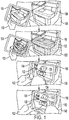
- FIG. 1 a series of perspective views illustrates a sequence according to an example embodiment.
- a user 102 holds a mobile device 104 (e.g., a tablet, mobile phone, laptop, wearable device, etc.) near a target object 106, which is in this example a multifunction printer (MFP).
- the mobile device 104 has a camera (not shown) which allows rendering a live video of the object 106 on a display.
- the mobile device 104 is configured to detect the presence of the object 106 based on the live video.
- the mobile device 104 may have a transparent window (e.g., AR glasses or headset), in which case the mobile device 104 may still utilize a camera or other imaging sensor to detect the target object 106, even though a video is not necessarily shown on the display.
- a transparent window e.g., AR glasses or headset
- the mobile device 104 may still utilize a camera or other imaging sensor to detect the target object 106, even though a video is not necessarily shown on the display.
- the mobile device 104 may detect the object via image recognition.
- a machine-learning model e.g., convolutional neural network
- a set of objects e.g., a set of model numbers in a manufacturer's produce range
- This model will serve as a representation that can be used to visually detect the object from a camera feed. Because such models can detect objects even at viewing angles that are different than what was trained on, the mobile device 104 can make a high-probability determination that the object 106 is a member of a class that the model was trained to detect.
- the representation of the object may include identifiers (e.g., binary or alphanumeric sequences) that represent the object 106 and may be used instead of or in addition to a machine-learned representation of the appearance of the object 106.
- identifiers e.g., binary or alphanumeric sequences
- a machine-readable code e.g., bar code, QR code, radio-frequency identifier tags
- QR code QR code
- radio-frequency identifier tags may be affixed to the object 106 and this can be used to identify the object 106 uniquely (e.g., serial number), and/or to identify the class of the object 106 (e.g., model number).
- Other codes that are not specifically designed for machine-reading e.g., human-readable text
- the mobile device 104 may still utilize a video camera feed in order to generally determine the orientation and location of the object 106 within the camera scene.
- the mobile device 104 accesses a three-dimensional geometry 122 of the object 106, here shown as a grid superimposed over the object 106.
- the three-dimensional geometry 122 may be stored on the mobile device 104 and/or accessed via a network.
- the three-dimensional geometry 122 may be a simple shape (e.g., cuboid) that encompasses a maximum extent of the object 106 or a more complex geometry, e.g., a set of interconnected surfaces. These geometries may be formed, for example, using a CAD model of the object 106 and/or a three-dimensional scan of the object 106.
- the mobile device 104 is configured to map the three-dimensional geometry 122 to the scene, such that the location of the geometry 122 within a virtual model of the scene matches that of the real object 106 in the scene.
- a representation of the three-dimensional geometry 122 e.g., a grid
- the mobile device 104 may also use a machine learning algorithm/model.
- a machine learning algorithm can be trained detect from the video image at least two physical points on the object (e.g., corners) that correspond to known reference points of the three-dimensional geometry 122. These detected points can be used achieve the mapping.
- Other indicia e.g., machine detectable markings, may also be used instead of or in addition to video image.
- machine detectable markings e.g., ink, stickers
- the user can physically indicate these regions by touching the device or using a pointing device (e.g., laser pointer).
- the mobile device 104 will be able to change the view of the three-dimensional geometry 122 on the display in response to movements of the mobile device 104, and these movements will map that of the object 106 within the view. This may be achieved based on location and orientation sensors utilized by the mobile device 104 that indicate an offset vector in three-dimensional space between the mobile device 104 and the target object 106. In this way, the mobile device 104 has enough information to render a virtual object located at a fixed point relative to the object 106 such that the virtual object is shown on an AR display as being located at the point regardless of a change in location of the augmented reality display relative to the object 106.
- the mobile device 106 is positioned a desired place such that the target object 106 is located within the live video feed shown on the mobile device 104. Then via a user interface of the mobile device (e.g., a touchscreen), the user 102 can add virtual objects that are attached to the target object 106.
- the user 102 writes a note 132, adds an animated arrow 133, and selects a video 134.
- the note 132, arrow 133, and video 134 are aligned using the exact pose and position of the mobile device 104.
- the user 102 also draws a line 142 between the virtual objects 132-134 to the surface of the object 106, indicating the exact anchor position of the virtual objects 132-134.
- the virtual objects are anchored to a part of interest, e.g., a cover of the MFP.
- the virtual objects 132-134 After the user has created the virtual objects 132-134, they can be saved to a database and linked to the object 106.
- the database may be the same or different than where the three-dimensional geometry 122 is stored.
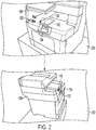
- the virtual objects 132-134 will be displayed in the device in the same orientation as was set in FIG. 1 .
- FIG. 2 This is shown in FIG. 2 , where views 200 and 202 represent what may be shown in an AR viewer after virtual objects 132-134 and 142 have been created and stored.
- View 200 represents a viewpoint that is similar to what was used when the virtual objects were created in FIG. 1 .
- View 202 represents a side view. Note that the virtual objects 132-133, having been constructed as two-dimensional objects on a plane, are rendered as plate-like objects hovering in front of the target object 106 when viewed from the side.
- the different device may have some capability to detect its location within the environment as well as data that describes where in the environment the actual object and virtual object are located.
- An illustrative example of location data that describes a three-dimensional geometry 300 is shown in the diagram of FIG. 3 . Note that this location data may be optional, as in some embodiments, the AR devices may be able to establish geometric reference points based on just an image of the object itself, thus do not strictly require any knowledge of the specific coordinates of the surroundings of the object.
- the coordinate system 302 represents a fixed reference usable by a device having location sensors (e.g., geolocation sensor, beacon sensor) that can be used to determine location at a defined space (e.g., within a room, at a globally unique latitude/longitude/elevation point).
- location sensors e.g., geolocation sensor, beacon sensor
- a reference point e.g., corner
- the geometry 300 is rotated relative to the coordinate system by vector ⁇ .
- the geometry 300 is attached to (e.g., encompasses) a real-world object 305 that is in the defined space.
- the vectors X, ⁇ can be stored such that another viewing device 308 with orientation and location sensors can determine the location of the geometry 300 (and thus the real-world object) relative to a local reference, e.g., focal point of a camera lens.
- a virtual object 304 can be attached to the geometry 300, and may have its own set of vectors Xv, ⁇ v that describe the location and orientation of the virtual object 304 to the geometry 300.
- the viewing device 308 can calculate the offset X + Xv, then apply the offset with rotation ⁇ v to a model of the virtual object 304. Then the device 308 will apply another set of transformations to make the object 304 appear correctly in a display relative to its own local reference.
- the viewing device 308 will have the ability to repeat the operations shown in FIG. 1 , such as visually recognizing the object 305 and aligning the geometry model 300 with the actual location and orientation of the object 305. This may occur each time the viewing device 308 encounters the object 305, or may be triggered based on some event, e.g., user request, some discrepancy detected by the AR application, etc.
- the ability of the viewing device 308 to detect the object 300 and reacquire and align the geometry model 300 may also be used to allow the appearance of the virtual objects 304 to similar objects at any location, and not just the location where the virtual object 304 was originally created and attached.
- the virtual object 304 may be an instruction (or set thereof) for servicing a device such as a printer.
- a facility may have a large number of such printers, and so it would be advantageous for the content creator to only make one instance of the virtual object 304 for each printer that illustrates a service task.
- This instance of the virtual object 304 could automatically be applied to other printers of the same type by the viewing devices 308 of end-users who can then access the same service instructions.
- FIG. 4 a diagram illustrates a system according to an example embodiment.
- the three-dimensional geometry 300, real-world object 305 and virtual object 304 from FIG. 3 are used.
- a creating device 400 is used to initially discover the object 305 and create the virtual object 304.
- a camera 402 can identify the object 305 via a representation of the object 305 that may be obtained via a representations database 421 available via a network 420.
- the representation may include, for example, an array of weights and biases that can be used in a convolutional neural network that classifies images produced by the camera 402.
- Other representations, e.g., machine-readable codes may also be available from the database 421.
- the database 421 (and other databases described below) may be stored locally on the creating device 400 (as well as viewing device 430, as appropriate).
- the creating device 400 Based on identifying the object 305 in an image, the creating device 400 obtains a three-dimensional geometry 300 of the object 305, which may be obtained, in one embodiment, from a network database 422. Such geometry 300 may be obtained from manufacturers CAD models, for example, although the CAD models may be simplified in order to decrease storage and processing requirements. In another embodiment, the creating device 400 may be able to scan the object 305 itself, as indicated by depth scanner 403, which can be used to acquire a full three-dimensional mesh of the object 305. In such a case, the creating device 400 may upload geometry to the database 422 where it can be accessed by other devices.
- the creating device 400 may optionally record the location of the object 305 via location sensor 404.
- the location sensor 404 may also include sensors that can detect orientation of the device 400, in particular the orientation of the camera 402 or other sensors. Orientation information may also be applied to the geometry 300 and stored in the database 422, e.g., defining which way the object 305 is facing.
- Location and orientation sensors 404 may include a geolocation sensor (e.g., global positioning system sensor) to determine a latitude and longitude of the device's current location, a compass to determine a direction the device 400, and accelerometers to determine a tilt of the device 400 relative to the earth's surface. Other sensors and systems may be used to determine equivalent location and orientation, e.g., radio frequency beacons, infrared markers, etc.
- the creating device 400 includes a user interface 405 that facilitates, among other things, verifying the application of the geometry 300 to the object 305, creating and validating the virtual object 304, and performing other computing tasks, e.g., accessing accounts on the network 420, changing settings on the AR application, etc.
- the user interface 405 may include hardware integrated with the creating device 400 such as touchscreens, buttons, touchpads, etc., and may also include other devices such as laser pointers or handheld controllers for marking locations in three-dimensional space, a microphone for receiving voice commands, etc.
- the creating device 400 may be a single mobile device or a collection of one or more devices, such as headsets, eyeglasses/goggles, tablets, smart phones, laptop computers, etc. Some amount of the processing for the creating device 400 may be provided via a service, such as a cloud processing service available via the network 420.
- the creating device 400 may include at least a central processing unit (CPU) 406, memory 407 (which includes both volatile and non-volatile memory) and input/output devices such as the aforementioned sensors and a network interface 408 which facilitates communications with the network 420.
- CPU central processing unit
- memory 407 which includes both volatile and non-volatile memory
- input/output devices such as the aforementioned sensors
- a network interface 408 which facilitates communications with the network 420.
- the viewing device 430 may be a mobile device or collection of devices similar to the creating device 400. Generally, the creating device 400 may have all of the capabilities of viewing device 430, but not vice versa. Thus, while the viewing device 430 will include a camera 432 for at least detecting the object 305, in some situations the viewing device may not need a location sensor 433 (shown as optional) even if one is used by the creating device 400. For example, if the viewing device can detect the presence of the object 305 and its location/orientation, e.g., through the camera 432, the capabilities of a precise location sensor 433 may not be needed.
- Geofencing can reduce the use of computing resources when not in the vicinity of virtual objects, and for other purposes such as limiting access to authorized areas, rendering location-specific versions of the virtual objects, etc.
- the viewing device 430 includes a user interface 434 that at least renders the virtual object 304. This rendering may take place within a video captured by the camera 432, or may be projected onto a transparent screen, e.g., onto the lenses of AR viewing glasses or the like.
- the user interface 434 may also facilitate interacting with the virtual object 304, e.g., stopping starting a video, hiding/showing some elements, moving the virtual object, etc.
- the viewing device 430 will generally include other computing hardware such as CPU 435, memory 436, and network interface 437.
- the viewing device 430 may also access the databases of the network 420 via the network interface 437, or have analogous databases stored locally in memory 436.
- an AR system may be used to facilitate providing instructions to help service a device. This can provide to a user, among other things, direct identification of parts, animations showing actions required for disassembly or assembly, validation of a state of the device.
- the geometry may change as panels are opened, parts are removed and added, etc.
- the AR system may apply different three-dimensional geometries to reflect a change in configuration of the real-world object due to servicing of the object.
- FIG. 5 a perspective view shows changes to a three-dimensional geometry used in an AR system according to an example embodiment.
- a three-dimensional geometry 500 is shown superimposed over a device 502.
- This geometry 500 may be a basic cuboid envelope that is useful for initial encounters with the device 502.
- an instruction is provided to open a cover 508.
- a second geometry 510 is mapped to the device 502 and used to locate new virtual objects 512, 514.
- the second geometry 510 includes details of the cavity behind the panel 508 and may also represent at least a portion of a removable part 516, which the user is being instructed to pull out via the virtual objects 512, 514.
- the additional geometries attached to the real-world object 502 may include sub-geometries that capture articulatable parts such as doors, panels, removable parts, etc. and their relationship to the larger object with respect to motion (e.g., degrees of freedom for a door, where a part attaches).
- Such sub-geometries may spawn new geometries for removable parts, such that the parts are treated for purposes of an AR viewer as objects that are independent of the former assembly.
- Systems and methods described herein facilitate training an AR "trigger” that allows a user to align a geometry (e.g., mathematically defined mesh) in real-time to a physical object of interest, e.g., thru a viewport of an AR device.
- Example viewports include a live camera feed of a camera displayed on a tablet, or a 3-D holographic viewport provided by a head-mounted display.
- the user can place two-dimensional and/or three-dimensional content at an area of interest in proximity to the object of interest.
- the content is initially aligned along the estimated pose and distance of the viewport from the object of interest.
- the content may be adjusted using affordances provided by the user interface of the device providing the viewport.
- Example persistent storage mechanisms include the cloud, a PC, tablet, or other device that stores the content. Using either the same or a different device, the content is loaded from the storage mechanism. Methods for loading the virtual content include an application, QR code, email link, etc. After loading content, the virtual content is then superimposed in the viewport as placed by the user who placed the content.
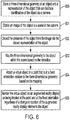
- a flowchart illustrates a method according to an example embodiment.
- the method involves storing 600 in memory a three-dimensional geometry of an object and a representation of the object that can facilitate identification of the object via a camera.
- An image of the object is obtained 601 via a scene in the camera.
- the presence of the object is detected 602 via the stored representation of the object.
- the three-dimensional geometry is mapped 603 to the object within the scene.
- a virtual object is attached 604 to a point that is at a fixed orientation relative to the three-dimensional geometry.
- the virtual object is rendered 605 on an augmented reality display as being located at the point and at the fixed orientation regardless of a change in location of the augmented reality display relative to the object. Note that while the blocks in the flowchart as shown in a specific order, in some embodiments the order may change and/or some processes may be performed in parallel instead of in order.
Landscapes
- Engineering & Computer Science (AREA)
- Physics & Mathematics (AREA)
- General Physics & Mathematics (AREA)
- Theoretical Computer Science (AREA)
- Computer Graphics (AREA)
- Computer Hardware Design (AREA)
- General Engineering & Computer Science (AREA)
- Software Systems (AREA)
- Multimedia (AREA)
- Computer Vision & Pattern Recognition (AREA)
- Processing Or Creating Images (AREA)
- User Interface Of Digital Computer (AREA)
Applications Claiming Priority (1)
| Application Number | Priority Date | Filing Date | Title |
|---|---|---|---|
| US16/798,583 US11263818B2 (en) | 2020-02-24 | 2020-02-24 | Augmented reality system using visual object recognition and stored geometry to create and render virtual objects |
Publications (1)
| Publication Number | Publication Date |
|---|---|
| EP3869468A1 true EP3869468A1 (en) | 2021-08-25 |
Family
ID=74561697
Family Applications (1)
| Application Number | Title | Priority Date | Filing Date |
|---|---|---|---|
| EP21155641.0A Withdrawn EP3869468A1 (en) | 2020-02-24 | 2021-02-05 | Augmented reality system using visual object recognition and stored geometry to create and render virtual objects |
Country Status (3)
| Country | Link |
|---|---|
| US (1) | US11263818B2 (enExample) |
| EP (1) | EP3869468A1 (enExample) |
| JP (1) | JP7548835B2 (enExample) |
Families Citing this family (9)
| Publication number | Priority date | Publication date | Assignee | Title |
|---|---|---|---|---|
| US11393202B2 (en) * | 2020-02-28 | 2022-07-19 | CareAR Holdings LLC | Augmented reality support platform |
| FR3117650B1 (fr) * | 2020-12-16 | 2023-09-08 | Schneider Electric Ind Sas | Procédé de gestion de l’affichage d’au moins une information, produit programme d’ordinateur, support d’information et système d’affichage associés |
| CN118215942A (zh) * | 2021-11-10 | 2024-06-18 | 三星电子株式会社 | 用于增强现实或虚拟现实环境中的虚拟对象定位的方法和系统 |
| CN114390214B (zh) * | 2022-01-20 | 2023-10-31 | 脸萌有限公司 | 一种视频生成方法、装置、设备以及存储介质 |
| US12254564B2 (en) * | 2022-02-14 | 2025-03-18 | Meta Platforms, Inc. | Artificial intelligence-assisted virtual object builder |
| US12190580B2 (en) * | 2022-05-31 | 2025-01-07 | CareAR Holdings LLC | System and method to create configurable, context sensitive functions in AR experiences |
| US12158796B2 (en) | 2022-07-28 | 2024-12-03 | Bank Of America Corporation | System and method for dynamic error resolution in extended reality using machine learning |
| US12132942B2 (en) * | 2023-02-13 | 2024-10-29 | XMReality AB (publ) | Communication method and system |
| US12153726B1 (en) * | 2023-06-30 | 2024-11-26 | Adobe Inc. | Integrating text of a document into an extended reality environment |
Citations (2)
| Publication number | Priority date | Publication date | Assignee | Title |
|---|---|---|---|---|
| US20130222369A1 (en) * | 2012-02-23 | 2013-08-29 | Charles D. Huston | System and Method for Creating an Environment and for Sharing a Location Based Experience in an Environment |
| US20190371067A1 (en) * | 2018-06-04 | 2019-12-05 | Facebook, Inc. | Mobile Persistent Augmented-Reality Experiences |
Family Cites Families (34)
| Publication number | Priority date | Publication date | Assignee | Title |
|---|---|---|---|---|
| US20070187266A1 (en) * | 2006-02-15 | 2007-08-16 | Porter Gilbert D | Method, apparatus, and system for tracking unique items |
| US9824495B2 (en) | 2008-09-11 | 2017-11-21 | Apple Inc. | Method and system for compositing an augmented reality scene |
| US9514434B2 (en) * | 2009-01-06 | 2016-12-06 | The Boeing Company | Apparatus and method for automatic work instruction generation |
| KR20140031163A (ko) * | 2010-09-29 | 2014-03-12 | 에어로보틱스, 인크. | 항공기의 비파괴 검사를 위한 신규한 시스템 및 방법 |
| US9424371B2 (en) * | 2010-11-05 | 2016-08-23 | Autodesk, Inc. | Click to accept as built modeling |
| JP5799521B2 (ja) | 2011-02-15 | 2015-10-28 | ソニー株式会社 | 情報処理装置、オーサリング方法及びプログラム |
| US9235819B2 (en) * | 2011-11-04 | 2016-01-12 | Canon Kabushiki Kaisha | Printing system, image forming apparatus, and method |
| CN109003398B (zh) * | 2012-06-14 | 2022-04-29 | 百利游戏技术有限公司 | 用于增强现实游戏的系统和方法 |
| EP2704055A1 (en) | 2012-08-31 | 2014-03-05 | Layar B.V. | Determining space to display content in augmented reality |
| US10269179B2 (en) * | 2012-10-05 | 2019-04-23 | Elwha Llc | Displaying second augmentations that are based on registered first augmentations |
| US20140240349A1 (en) * | 2013-02-22 | 2014-08-28 | Nokia Corporation | Method and apparatus for presenting task-related objects in an augmented reality display |
| US9070202B2 (en) * | 2013-03-14 | 2015-06-30 | Nec Laboratories America, Inc. | Moving object localization in 3D using a single camera |
| US20150062123A1 (en) * | 2013-08-30 | 2015-03-05 | Ngrain (Canada) Corporation | Augmented reality (ar) annotation computer system and computer-readable medium and method for creating an annotated 3d graphics model |
| JP6314394B2 (ja) | 2013-09-13 | 2018-04-25 | 富士通株式会社 | 情報処理装置、設定方法、設定プログラム、システムおよび管理装置 |
| US9740935B2 (en) * | 2013-11-26 | 2017-08-22 | Honeywell International Inc. | Maintenance assistant system |
| US9898844B2 (en) * | 2013-12-31 | 2018-02-20 | Daqri, Llc | Augmented reality content adapted to changes in real world space geometry |
| US9432421B1 (en) * | 2014-03-28 | 2016-08-30 | A9.Com, Inc. | Sharing links in an augmented reality environment |
| AU2014202574A1 (en) | 2014-05-13 | 2015-12-03 | Canon Kabushiki Kaisha | Positioning of projected augmented reality content |
| US9824499B2 (en) * | 2015-06-23 | 2017-11-21 | Microsoft Technology Licensing, Llc | Mixed-reality image capture |
| US9520002B1 (en) | 2015-06-24 | 2016-12-13 | Microsoft Technology Licensing, Llc | Virtual place-located anchor |
| US20170200316A1 (en) | 2015-09-10 | 2017-07-13 | Sphere Optics Company, Llc | Advertising system for virtual reality environments |
| KR101624670B1 (ko) * | 2015-09-25 | 2016-05-26 | 주식회사 동우 이앤씨 건축사사무소 | 구조물의 모델링에 관한 정보를 제공하기 위한 방법, 시스템 및 컴퓨터 판독 가능한 기록 매체 |
| US9805343B2 (en) * | 2016-01-05 | 2017-10-31 | Intermec Technologies Corporation | System and method for guided printer servicing |
| US10306315B2 (en) | 2016-03-29 | 2019-05-28 | International Business Machines Corporation | Video streaming augmenting |
| JP7002536B2 (ja) * | 2016-08-22 | 2022-01-20 | マジック リープ, インコーポレイテッド | 深層学習センサを有する拡張現実ディスプレイデバイス |
| US10140773B2 (en) * | 2017-02-01 | 2018-11-27 | Accenture Global Solutions Limited | Rendering virtual objects in 3D environments |
| WO2018222756A1 (en) * | 2017-05-30 | 2018-12-06 | Ptc Inc. | Object initiated communication |
| US11345040B2 (en) * | 2017-07-25 | 2022-05-31 | Mbl Limited | Systems and methods for operating a robotic system and executing robotic interactions |
| DK180470B1 (en) * | 2017-08-31 | 2021-05-06 | Apple Inc | Systems, procedures, and graphical user interfaces for interacting with augmented and virtual reality environments |
| US11592818B2 (en) * | 2018-06-20 | 2023-02-28 | Zoox, Inc. | Restricted multi-scale inference for machine learning |
| WO2020069525A1 (en) * | 2018-09-28 | 2020-04-02 | Jido, Inc. | Method for detecting objects and localizing a mobile computing device within an augmented reality experience |
| US10679420B2 (en) * | 2018-11-02 | 2020-06-09 | General Motors Llc | Augmented reality (AR) remote vehicle assistance |
| US11087541B2 (en) * | 2018-12-03 | 2021-08-10 | Honeywell International Inc. | Location-based identification of petrochemical assets in an industrial plant |
| US10846899B2 (en) * | 2019-04-17 | 2020-11-24 | Honeywell International Inc. | Methods and systems for augmented reality safe visualization during performance of tasks |
-
2020
- 2020-02-24 US US16/798,583 patent/US11263818B2/en active Active
-
2021
- 2021-02-03 JP JP2021016096A patent/JP7548835B2/ja active Active
- 2021-02-05 EP EP21155641.0A patent/EP3869468A1/en not_active Withdrawn
Patent Citations (2)
| Publication number | Priority date | Publication date | Assignee | Title |
|---|---|---|---|---|
| US20130222369A1 (en) * | 2012-02-23 | 2013-08-29 | Charles D. Huston | System and Method for Creating an Environment and for Sharing a Location Based Experience in an Environment |
| US20190371067A1 (en) * | 2018-06-04 | 2019-12-05 | Facebook, Inc. | Mobile Persistent Augmented-Reality Experiences |
Non-Patent Citations (2)
| Title |
|---|
| JURI PLATONOV ET AL: "A mobile markerless AR system for maintenance and repair", MIXED AND AUGMENTED REALITY, 2006. ISMAR 2006. IEEE/ACM INTERNATIONAL SYMPOSIUM ON, IEEE, PI, 22 October 2006 (2006-10-22), pages 105 - 108, XP058378969, ISBN: 978-1-4244-0650-0, DOI: 10.1109/ISMAR.2006.297800 * |
| STEVEN HENDERSON ET AL: "Exploring the Benefits of Augmented Reality Documentation for Maintenance and Repair", IEEE TRANSACTIONS ON VISUALIZATION AND COMPUTER GRAPHICS, IEEE SERVICE CENTER, LOS ALAMITOS, CA, US, vol. 17, no. 10, 1 October 2011 (2011-10-01), pages 1355 - 1368, XP011373314, ISSN: 1077-2626, DOI: 10.1109/TVCG.2010.245 * |
Also Published As
| Publication number | Publication date |
|---|---|
| US11263818B2 (en) | 2022-03-01 |
| US20210264669A1 (en) | 2021-08-26 |
| JP7548835B2 (ja) | 2024-09-10 |
| JP2021136017A (ja) | 2021-09-13 |
Similar Documents
| Publication | Publication Date | Title |
|---|---|---|
| US11263818B2 (en) | Augmented reality system using visual object recognition and stored geometry to create and render virtual objects | |
| US11887312B2 (en) | Fiducial marker patterns, their automatic detection in images, and applications thereof | |
| US11481999B2 (en) | Maintenance work support system and maintenance work support method | |
| US20250321650A1 (en) | Augmented reality eyewear 3d painting | |
| US11054918B2 (en) | Position-based location indication and device control | |
| JP7079231B2 (ja) | 情報処理装置及び情報処理システム及び制御方法、プログラム | |
| KR101691903B1 (ko) | 광학 캐릭터 인식을 사용하여 증강 현실을 제공하기 위한 방법 및 장치 | |
| CN110533723B (zh) | 增强现实显示的方法、姿态信息的确定方法及装置 | |
| US10083544B2 (en) | System for tracking a handheld device in virtual reality | |
| EP4342196A1 (en) | Beacons for localization and content delivery to wearable devices | |
| CN1698357B (zh) | 在物体上显示输出图像的方法 | |
| KR20230028532A (ko) | 가상 현실 경험들을 위한 지상 실측값 데이터세트들의 생성 | |
| JP2016122392A (ja) | 情報処理装置、情報処理システム、その制御方法及びプログラム | |
| US12047674B2 (en) | System for generating a three-dimensional scene of a physical environment | |
| TWI750822B (zh) | 用於為目標設置可呈現的虛擬對象的方法和系統 | |
| Diaz et al. | Multimodal sensing interface for haptic interaction | |
| CN112581630B (zh) | 一种用户交互方法和系统 | |
| CN114323013A (zh) | 用于确定设备在场景中的位置信息的方法 | |
| US12260498B1 (en) | Method and system for identifying and tracking an object in space and generating digital twin contents including a corresponding object with regard to the space | |
| CN112561953B (zh) | 用于现实场景中的目标识别与跟踪的方法和系统 | |
| CN114827338A (zh) | 用于在设备的显示媒介上呈现虚拟对象的方法和电子装置 |
Legal Events
| Date | Code | Title | Description |
|---|---|---|---|
| PUAI | Public reference made under article 153(3) epc to a published international application that has entered the european phase |
Free format text: ORIGINAL CODE: 0009012 |
|
| STAA | Information on the status of an ep patent application or granted ep patent |
Free format text: STATUS: THE APPLICATION HAS BEEN PUBLISHED |
|
| AK | Designated contracting states |
Kind code of ref document: A1 Designated state(s): AL AT BE BG CH CY CZ DE DK EE ES FI FR GB GR HR HU IE IS IT LI LT LU LV MC MK MT NL NO PL PT RO RS SE SI SK SM TR |
|
| STAA | Information on the status of an ep patent application or granted ep patent |
Free format text: STATUS: REQUEST FOR EXAMINATION WAS MADE |
|
| 17P | Request for examination filed |
Effective date: 20220225 |
|
| RBV | Designated contracting states (corrected) |
Designated state(s): AL AT BE BG CH CY CZ DE DK EE ES FI FR GB GR HR HU IE IS IT LI LT LU LV MC MK MT NL NO PL PT RO RS SE SI SK SM TR |
|
| STAA | Information on the status of an ep patent application or granted ep patent |
Free format text: STATUS: EXAMINATION IS IN PROGRESS |
|
| 17Q | First examination report despatched |
Effective date: 20230619 |
|
| STAA | Information on the status of an ep patent application or granted ep patent |
Free format text: STATUS: THE APPLICATION IS DEEMED TO BE WITHDRAWN |
|
| 18D | Application deemed to be withdrawn |
Effective date: 20240903 |