EP3869255A1 - Optical system and image pickup apparatus having the same - Google Patents
Optical system and image pickup apparatus having the same Download PDFInfo
- Publication number
- EP3869255A1 EP3869255A1 EP21157630.1A EP21157630A EP3869255A1 EP 3869255 A1 EP3869255 A1 EP 3869255A1 EP 21157630 A EP21157630 A EP 21157630A EP 3869255 A1 EP3869255 A1 EP 3869255A1
- Authority
- EP
- European Patent Office
- Prior art keywords
- lens
- optical system
- conditional expression
- positive lens
- satisfied
- Prior art date
- Legal status (The legal status is an assumption and is not a legal conclusion. Google has not performed a legal analysis and makes no representation as to the accuracy of the status listed.)
- Granted
Links
Images


Classifications
-
- G—PHYSICS
- G02—OPTICS
- G02B—OPTICAL ELEMENTS, SYSTEMS OR APPARATUS
- G02B15/00—Optical objectives with means for varying the magnification
- G02B15/14—Optical objectives with means for varying the magnification by axial movement of one or more lenses or groups of lenses relative to the image plane for continuously varying the equivalent focal length of the objective
- G02B15/142—Optical objectives with means for varying the magnification by axial movement of one or more lenses or groups of lenses relative to the image plane for continuously varying the equivalent focal length of the objective having two groups only
- G02B15/1421—Optical objectives with means for varying the magnification by axial movement of one or more lenses or groups of lenses relative to the image plane for continuously varying the equivalent focal length of the objective having two groups only the first group being positive
-
- G—PHYSICS
- G02—OPTICS
- G02B—OPTICAL ELEMENTS, SYSTEMS OR APPARATUS
- G02B9/00—Optical objectives characterised both by the number of the components and their arrangements according to their sign, i.e. + or -
- G02B9/60—Optical objectives characterised both by the number of the components and their arrangements according to their sign, i.e. + or - having five components only
-
- G—PHYSICS
- G02—OPTICS
- G02B—OPTICAL ELEMENTS, SYSTEMS OR APPARATUS
- G02B13/00—Optical objectives specially designed for the purposes specified below
- G02B13/001—Miniaturised objectives for electronic devices, e.g. portable telephones, webcams, PDAs, small digital cameras
- G02B13/0015—Miniaturised objectives for electronic devices, e.g. portable telephones, webcams, PDAs, small digital cameras characterised by the lens design
- G02B13/002—Miniaturised objectives for electronic devices, e.g. portable telephones, webcams, PDAs, small digital cameras characterised by the lens design having at least one aspherical surface
- G02B13/0045—Miniaturised objectives for electronic devices, e.g. portable telephones, webcams, PDAs, small digital cameras characterised by the lens design having at least one aspherical surface having five or more lenses
-
- G—PHYSICS
- G02—OPTICS
- G02B—OPTICAL ELEMENTS, SYSTEMS OR APPARATUS
- G02B13/00—Optical objectives specially designed for the purposes specified below
- G02B13/001—Miniaturised objectives for electronic devices, e.g. portable telephones, webcams, PDAs, small digital cameras
- G02B13/0055—Miniaturised objectives for electronic devices, e.g. portable telephones, webcams, PDAs, small digital cameras employing a special optical element
- G02B13/006—Miniaturised objectives for electronic devices, e.g. portable telephones, webcams, PDAs, small digital cameras employing a special optical element at least one element being a compound optical element, e.g. cemented elements
-
- G—PHYSICS
- G02—OPTICS
- G02B—OPTICAL ELEMENTS, SYSTEMS OR APPARATUS
- G02B13/00—Optical objectives specially designed for the purposes specified below
- G02B13/18—Optical objectives specially designed for the purposes specified below with lenses having one or more non-spherical faces, e.g. for reducing geometrical aberration
-
- G—PHYSICS
- G02—OPTICS
- G02B—OPTICAL ELEMENTS, SYSTEMS OR APPARATUS
- G02B3/00—Simple or compound lenses
- G02B3/0087—Simple or compound lenses with index gradient
-
- G—PHYSICS
- G02—OPTICS
- G02B—OPTICAL ELEMENTS, SYSTEMS OR APPARATUS
- G02B3/00—Simple or compound lenses
- G02B3/02—Simple or compound lenses with non-spherical faces
- G02B3/04—Simple or compound lenses with non-spherical faces with continuous faces that are rotationally symmetrical but deviate from a true sphere, e.g. so called "aspheric" lenses
-
- G—PHYSICS
- G02—OPTICS
- G02B—OPTICAL ELEMENTS, SYSTEMS OR APPARATUS
- G02B9/00—Optical objectives characterised both by the number of the components and their arrangements according to their sign, i.e. + or -
- G02B9/04—Optical objectives characterised both by the number of the components and their arrangements according to their sign, i.e. + or - having two components only
- G02B9/06—Optical objectives characterised both by the number of the components and their arrangements according to their sign, i.e. + or - having two components only two + components
- G02B9/08—Optical objectives characterised both by the number of the components and their arrangements according to their sign, i.e. + or - having two components only two + components arranged about a stop
-
- G—PHYSICS
- G02—OPTICS
- G02B—OPTICAL ELEMENTS, SYSTEMS OR APPARATUS
- G02B9/00—Optical objectives characterised both by the number of the components and their arrangements according to their sign, i.e. + or -
- G02B9/62—Optical objectives characterised both by the number of the components and their arrangements according to their sign, i.e. + or - having six components only
-
- G—PHYSICS
- G03—PHOTOGRAPHY; CINEMATOGRAPHY; ANALOGOUS TECHNIQUES USING WAVES OTHER THAN OPTICAL WAVES; ELECTROGRAPHY; HOLOGRAPHY
- G03B—APPARATUS OR ARRANGEMENTS FOR TAKING PHOTOGRAPHS OR FOR PROJECTING OR VIEWING THEM; APPARATUS OR ARRANGEMENTS EMPLOYING ANALOGOUS TECHNIQUES USING WAVES OTHER THAN OPTICAL WAVES; ACCESSORIES THEREFOR
- G03B17/00—Details of cameras or camera bodies; Accessories therefor
- G03B17/02—Bodies
- G03B17/12—Bodies with means for supporting objectives, supplementary lenses, filters, masks, or turrets
-
- H—ELECTRICITY
- H04—ELECTRIC COMMUNICATION TECHNIQUE
- H04N—PICTORIAL COMMUNICATION, e.g. TELEVISION
- H04N23/00—Cameras or camera modules comprising electronic image sensors; Control thereof
- H04N23/50—Constructional details
- H04N23/55—Optical parts specially adapted for electronic image sensors; Mounting thereof
-
- G—PHYSICS
- G02—OPTICS
- G02B—OPTICAL ELEMENTS, SYSTEMS OR APPARATUS
- G02B13/00—Optical objectives specially designed for the purposes specified below
- G02B13/02—Telephoto objectives, i.e. systems of the type + - in which the distance from the front vertex to the image plane is less than the equivalent focal length
-
- G—PHYSICS
- G02—OPTICS
- G02B—OPTICAL ELEMENTS, SYSTEMS OR APPARATUS
- G02B3/00—Simple or compound lenses
- G02B2003/0093—Simple or compound lenses characterised by the shape
Definitions
- the present invention relates to an optical system suitable for an image pickup apparatus, such as a digital camera and a video camera.
- JP 5-039284 describes a double Gaussian type optical system that can correct various aberrations with a small number of lenses.
- the double Gaussian type optical system as disclosed in JP 5-039284 has difficulty in satisfactorily correcting various aberrations, such as the spherical aberration and the curvature of field, when the symmetry is broken along with the miniaturization.
- various aberrations such as the spherical aberration and the curvature of field
- the optical system has a large aperture ratio, it becomes difficult to suppress the sagittal flare and coma flare at an intermediate angle of view.
- the present invention provides a compact optical system having a large aperture ratio and an image pickup apparatus having the same, each of which can provide a high optical performance.
- the present invention in its first aspect provides an optical system as specified in claims 1 to 14.
- the present invention in its second aspect provides an image pickup apparatus as specified in claim 15.
- FIGs. 1 , 3 , and 5 are sectional views of optical systems (imaging optical systems) 1a to 1c according to Examples 1 to 3, respectively, with an object distance at infinity.
- Each of the optical systems 1a to 1c includes, in order from an object side to an image side, substantially two units including a front unit LF having a positive refractive power, an aperture stop (diaphragm) STO, and a rear unit LR having a positive refractive power.
- the front unit LF substantially includes, in order from the object side to the image side, three lenses including a positive lens (lens with a positive refractive power) L11, a positive lens L12, and a negative lens (lens with a negative refractive power) L13.
- the rear unit LR substantially includes a negative lens L21, a positive lens L22, and a positive lens L23.
- the positive lens L11 is a meniscus lens that is convex on the object side, and has the largest effective diameter among the constituent lenses.
- the positive lens L12 is a meniscus lens that is convex on the object side, and is the thickest on the optical axis among the constituent lenses.
- the negative lens L13 is a meniscus lens that is convex on the object side and the closest to the aperture stop STO.
- the positive lens L12 and the negative lens L13 is a cemented lens cemented by an adhesive agent, and the combined refractive power is negative.
- the negative lens L21 is a lens concave on the object side, and has the smallest effective diameter among the constituent lenses.
- the radius of curvature of the image-side surface of the negative lens L21 is larger than that of the object-side surface of the negative lens L21.
- the positive lens L22 is a meniscus-shaped aspherical lens that is convex on the image side, and is made of a resin material.
- the positive lens L23 has a biconvex shape with a strong curvature of the surface on the image side.
- the radius of curvature of the surface on the object side of the positive lens L23 is larger than that of the surface on the image side of the positive lens L23.
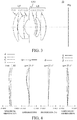
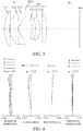
- FIGs. 2 , 4 , and 6 are aberration diagrams showing the imaging performance of the optical systems 1a to 1c, respectively, with an object distance at infinity.
- the spherical aberration, the astigmatism, the distortion, and the chromatic aberration are shown in order from the left side, respectively.
- a solid line indicates the aberration for the d-line (587.56 nm)
- a broken line indicates the aberration for the F-line (486.13 nm)
- an alternate long and short dash line indicates the aberration for the C-line (656.27 nm)
- an alternate long and short two dash lines indicates the aberration for the g-line (435.83 nm).
- the scale on the abscissa axis is a defocus amount, which is -0.400 to +0.400 [mm].
- a solid line shows the curvature of field of the sagittal image plane
- a dotted line shows the curvature of field of the meridional image plane.
- the abscissa axis is the same as that in the spherical aberration.
- the scale on the abscissa axis is indicated by -5.000 to +5.000 [%].
- the chromatic aberration indicates a shift of the lateral chromatic aberration from the d-line, and the scale on the abscissa axis is -0.050 to +0.050 [mm].
- the optical systems 1a to 1c separate the rear-unit joints of the conventional six-unit double Gaussian lens, weaken the refractive power of each lens in the rear unit to reduce the curvature of field, and introduce an aspherical surface with a weak refractive power to the positive lens L22 to suppress the coma flare at an intermediate angle of view.
- the optical systems 1a to 1c increase the refractive power of the front unit LF across the aperture stop STO, and decrease the refractive power of the rear unit LR relative to the front unit LF. Thereby, the telephoto tendency is enhanced across the aperture stop STO, and the length from the lens surface (lens first surface) closest to the object to the image plane img in each of the optical systems 1a to 1c is shortened.
- conditional expression (1) 1.00 ⁇ fF / fR ⁇ 2.00 where fF is a focal length of the front unit LF, and fR is a focal length of the rear unit LR.
- the value is higher than the upper limit in the conditional expression (1), the backfocus becomes too long, and it becomes difficult to shorten the overall length (overall lens length) of the optical systems 1a to 1c, or it becomes difficult to make a large aperture ratio.
- the value is lower than the lower limit in the conditional expression (1), the negative refractive power of the front unit LF is insufficient and the curvature of field cannot be suppressed.
- the rear unit LR includes a weak negative lens L21 with a strong concave surface on the object side, a weak positive lens L22 with a strong convex surface on the image side, and a positive lens L23.
- conditional expression (2) is satisfied: 1.00 ⁇ f 22 / f where f is a focal lengths of the optical systems 1a to 1c (overall system) and f22 is a focal length of the positive lens L22.
- conditional expressions (3) and (4) may be satisfied: ⁇ 2.00 ⁇ f 21 / f ⁇ ⁇ 0.50 0.30 ⁇ f 23 / f ⁇ 1.10 where f21 is a focal length of the negative lens L21, and f23 is a focal length of the positive lens L23.
- the optical system By weakening the refractive powers of the negative lens L21 and the positive lens L22, the curvature of field is suppressed, and as illustrated in the aberration diagrams of FIGs. 2 , 4 and 6 , the astigmatic difference is suppressed so that the meridional section and the sagittal section can have commensurate curvatures of field.
- the negative and positive power arrangement can be easily made in the rear unit LR by slightly enhancing the refractive power of the positive lens L23, and the miniaturization and large aperture ratio can be easily made by moving the principal point to the object side. Since the lens diameter of the rear unit LR can be reduced by weakening the refractive powers of the negative lens L21 and the positive lens L22, the optical system can be made smaller and lighter.
- the positive lens L22 may be a meniscus-shaped aspherical lens (a meniscus lens having a convex surface on the image side) that is convex on the image side.
- This configuration can easily balance the curvature of field and the spherical aberration while reducing the coma flare at the intermediate angle of view that may occur along with the miniaturization of the optical system. Since a lens having a strong refractive power is disposed on the front side (object side) of the aperture stop STO, it is difficult to manufacture an aspherical structure.
- the positive lens L22 may be an aspherical lens made of a resin material. Since the positive lens L22 has a structure with a suppressed refractive power, it is resistant to changes in thermal characteristic due to the resin material, and since it has a light specific gravity, it is easy to reduce the weight.
- R1a is a radius of curvature of the lens surface closest to the image plane of the front unit LF
- R2a is a radius of curvature of the lens surface closest to the object of the rear unit LR.
- an air lens is formed by the lens surface having the radius of curvature R1a and the lens surface having the radius of curvature R2a.
- the radius of curvature of the surface on the image side of the air lens is larger than that of the surface on the object side of the air lens (R1a ⁇ R2a), and the following conditional expression (5) may be satisfied. 0.08 ⁇ R 2 a + R 1 a / R 2 a ⁇ R 1 a ⁇ 0.80
- the optical system according to each example can suppress the sagittal flare by satisfying the conditional expression (5).
- it becomes easy to realize a large aperture by applying the positive and negative power arrangement to the front unit LF and by increasing the curvature of the surface of the aperture stop STO closest to the object.
- the radius of curvature R1a becomes too small (the curvature becomes too large), and the manufacturability deteriorates.
- the radius of curvature R2a becomes smaller (the curvature becomes larger), the shape of the air lens becomes nearly symmetric and it becomes difficult to correct the sagittal flare along with the miniaturization, similar to the conventional double Gaussian type optical system.
- R1b is a radius of curvature of a lens surface on the image side of the negative lens L21
- R2b is a radius of curvature of a lens surface on the object side of the positive lens L22.
- an air lens having a convex surface on the image side may be formed between the negative lens L21 and the positive lens L22, and the following conditional expression (6) may be satisfied.
- the Petzval sum can be maintained within an allowable range. If the value is outside the range of the conditional expression (6), the balance of the Petzval sum substantially corrected by the combination of the negative lens L21 and the positive lens L22 breaks and the curvature of field would occur.
- conditional expression (7) may be satisfied: 0.30 ⁇ BF / f ⁇ 0.70 where f is a focal length of each of the optical systems 1a to 1c, and BF is a distance from the lens surface (final lens surface) closest to the image plane of the optical systems 1a to 1c to an image plane mg on the optical axis.
- the conditional expression (7) shows a balance of the backfocus relative to the focal length, and if the value is lower than the lower limit, the backfocus becomes too short and the lens diameter of the rear unit LR becomes too large. If the value is higher than the upper limit, the backfocus is too long and the desired miniaturization cannot be achieved, or the overall lens length, which is a distance from the first lens surface to the final lens surface, becomes extremely short.
- conditional expression (8) may be satisfied 0.60 ⁇ Lst / f ⁇ 1.00 where f is the focal length of each of the optical systems 1a to 1c, and Lst is a distance from the aperture stop STO to the image plane img.
- the conditional expression (8) represents a preferable position of the diaphragm in the lens, and if the value is higher than the upper limit, the diaphragm position moves too closer to the image plane relative to the rear principal point of the lens, and the desired miniaturization cannot be achieved. If the value is lower than the lower limit, the diaphragm position moves too closer to object, and a large aperture becomes difficult or an improvement of a peripheral light amount becomes insufficient when the aperture of the diaphragm is narrowed.
- conditional expression (9) may be satisfied: 1.00 ⁇ TTL / f ⁇ 1.40 where f is the focal length of each of the optical systems 1a to 1c, and TTL is a distance from the lens surface (first lens surface) closest to the object of the optical system to the image plane img on the optical axis.
- conditional expression (9) expresses a proper range of this configuration in the miniaturization, and if the value is higher than the upper limit, the desired miniaturization cannot be obtained. If the value is lower than the lower limit in the conditional expression (9), a large aperture becomes difficult to realize, or a sufficient imaging performance cannot be obtained.
- the conventional double Gaussian type correct the off-axis coma by forming an air lens between the second lens and the third lens before the diaphragm, but when unnecessary light enters the lens a total reflection ghost caused by this air lens is likely to occur.
- the positive lens L12 and the negative lens L13 may form a cemented lens.
- conditional expression (10) may be satisfied: 4.50 ⁇ d 12 / d 13 ⁇ 10.00 where d12 is a thickness of the positive lens L12 on the optical axis and d13 is a thickness of the negative lens L13 on the optical axis.
- the ghost light diffused by the adhesive pool around the cemented surface can be reduced by satisfying the condition expression (10), when the positive lens L12 and the negative lens L13 are made into a cemented lens. If the value is higher than the upper limit in the conditional expression (10), the positive lens L12 becomes too thick, which prevents the overall length from reducing, and the position of the diaphragm becomes too closer to the image plane. On the other hand, if the value is lower than the lower limit in the conditional expression (10), the ghost light of the adhesive pool is likely to occur.
- conditional expression (11) may be satisfied: 0.70 ⁇ N 22 / N 23 ⁇ 1.00 where N22 is a refractive index of the positive lens L22, and N23 is a refractive index of the positive lens L23.
- conditional expression (11) By satisfying the conditional expression (11), it becomes easy to satisfy the conditional expressions (2), (3), and (4). If the value is higher than the upper limit in the conditional expression (11), the curvature of the lens becomes unnecessarily small in order to obtain the required refractive power of the positive lens L23, and the curvature of field cannot be sufficiently corrected. On the other hand, if the value is lower than the lower limit in the conditional expression (11), the lens dispersion of the positive lens L23 becomes too large in view of the existing glass, and the lateral chromatic aberration cannot be satisfactorily corrected.
- NdF is an average refractive index of the lenses constituting the front unit LF (which are the positive lenses L11 and L12 and the negative lens L13)
- NdR is an average refractive index of the lenses constituting the rear unit LR (which are the negative lens L21 and the positive lenses L22 and L23).
- conditional expression (12) It becomes easy to satisfy the conditional expression (1) by satisfying the conditional expression (12). If the value is higher than the upper limit in the conditional expression (12), the refractive power of the rear unit LR is too low, and a desired large aperture becomes difficult to realize. On the other hand, if the value is lower than the lower limit in the conditional expression (12), the refractive power of the front unit LF is too low, and the miniaturization becomes difficult.
- the numerical ranges of the conditional expressions (1) to (12) may be set as in the following conditional expressions (1a) to (12a). 1.20 ⁇ fF / fR ⁇ 1.90 1.20 ⁇ f 22 / f ⁇ 1.60 ⁇ f 21 / f ⁇ ⁇ 0.60 0.40 ⁇ f 23 / f ⁇ 1.00 0.12 ⁇ R 2 a + R 1 a / R 2 a ⁇ R 1 a ⁇ 0.60 R 2 b + R 1 b / R 2 b ⁇ R 1 b ⁇ ⁇ 0.50 0.35 ⁇ BF / f ⁇ 0.65 0.65 ⁇ Lst / f ⁇ 0.95 1.05 ⁇ TTL / f ⁇ 1.35 5.00 ⁇ d 12 / d 13 ⁇ 8.00 0.75 ⁇ N 22 / N 23 ⁇ 0.95 1.06 ⁇ NdF / NdR ⁇ 1.30
- the numerical ranges of the conditional expressions (1) to (12) may be set as in the following conditional expressions (1b) to (12b): 1.50 ⁇ fF / fR ⁇ 1.80 1.50 ⁇ f 22 / f ⁇ 1.30 ⁇ f 21 / f ⁇ ⁇ 0.70 0.50 ⁇ f 23 / f ⁇ 0.90 0.15 ⁇ R 2 a + R 1 a / R 2 a ⁇ R 1 a ⁇ 0.40 R 2 b + R 1 b / R 2 b ⁇ R 1 b ⁇ ⁇ 1.00 0.45 ⁇ BF / f ⁇ 0.60 0.70 ⁇ Lst / f ⁇ 0.90 1.10 ⁇ TTL / f ⁇ 1.30 5.5 ⁇ d 12 / d 13 ⁇ 7.0 0.80 ⁇ N 22 / N 23 ⁇ 0.90 1.06 ⁇ NdF / NdR ⁇ 1.20
- Each of the optical systems 1a to 1c can provide focusing in response to a change of the object distance by simultaneously feeding the front unit LF, the aperture stop STO, and the rear unit LR, and can obtain a sufficient optical performance from an object distance at infinity to an imaging magnification of up to about 0.2 times.
- r represents a radius of curvature of each optical surface
- d (mm) represents an axial distance (distance on the optical axis) between an m-th surface and an (m+1)-th surface, where m is the number of a surface counted from the light incident side (object side).
- nd represents a refractive index of each optical element for the d-line
- vd represents an Abbe number of the optical element.
- vd Nd ⁇ 1 / NF ⁇ NC
- Nd, NF, and NC are refractive indexes of the d-line (587.6 nm), F-line (486.1 nm), and C-line (656.3 nm) in the Fraunhofer line.
- d focal length (mm), F-number, and half angle of view (°) are values when the optical system according to each example focuses on an object at infinity.
- a backfocus (BF) is a distance on the optical axis from the final lens surface (the lens surface closest to the image plane) to the paraxial image plane in terms of the air equivalent length.
- the overall lens length is a length obtained by adding the backfocus to the distance on the optical axis from the first lens surface (the lens surface closest to the object) in the optical system to the final lens surface.
- optical surface is an aspherical surface
- a sign * is attached to the right side of the surface number.
- x is a displacement amount from the surface vertex in the optical axis direction
- h is a height from the optical axis in the direction orthogonal to the optical axis
- R is a paraxial radius of curvature
- k is a conical constant
- A4, A6, A8, A10, and A12 are aspherical coefficients of each order.
- "e ⁇ XX" in each aspherical coefficient means "x10 ⁇ XX ".
- Table 1 shows various values including the numerical values of each conditional expression in each numerical example.
- reference numeral 101 denotes a camera body
- reference numeral 102 denotes an imaging optical system (interchangeable lens) configured by any of the optical systems 1a to 1c according to Examples 1 to 3.
- Reference numeral 103 denotes an image sensor (photoelectric conversion element) such as a CCD sensor or a CMOS sensor, which is built in the camera body 101 and receives an optical image formed by the imaging optical system 102 and performs a photoelectric conversion.
- the camera body 101 may be a so-called single-lens reflex camera having a quick turn mirror, or a so-called mirrorless camera having no quick turn mirror.
- a so-called single-lens reflex camera having a quick turn mirror or a so-called mirrorless camera having no quick turn mirror.
- Each example is applicable to an image pickup apparatus in which a camera body and an imaging optical system are integrated with each other.
- Each example can provide a compact, lightweight, large-aperture optical system, and an image pickup apparatus having the same.
- each example may use a configuration in which a lens unit having a weak refractive power is disposed on the object side or the image side of the lens, or a configuration in which a lens having a weak refractive power is disposed before the front unit LF or after the rear unit LR.
- the optical system according to each example can provide similar effects even if it further includes another lens.
Landscapes
- Physics & Mathematics (AREA)
- General Physics & Mathematics (AREA)
- Optics & Photonics (AREA)
- Engineering & Computer Science (AREA)
- Multimedia (AREA)
- Signal Processing (AREA)
- Lenses (AREA)
Abstract
Description
- The present invention relates to an optical system suitable for an image pickup apparatus, such as a digital camera and a video camera.
- Japanese Patent (Examined) Publication No. ("
JP") 5-039284 - However, the double Gaussian type optical system as disclosed in
JP 5-039284 - The present invention provides a compact optical system having a large aperture ratio and an image pickup apparatus having the same, each of which can provide a high optical performance.
- The present invention in its first aspect provides an optical system as specified in claims 1 to 14.
- The present invention in its second aspect provides an image pickup apparatus as specified in claim 15.
- Further features of the present invention will become apparent from the following description of exemplary embodiments with reference to the attached drawings.
-
-
FIG. 1 is a sectional view of an optical system according to Example 1. -
FIG. 2 is an aberration diagram of the optical system according to Example 1. -
FIG. 3 is a sectional view of an optical system according to Example 2. -
FIG. 4 is an aberration diagram of the optical system according to Example 2. -
FIG. 5 is a sectional view of an optical system according to Example 3. -
FIG. 6 is an aberration diagram of the optical system according to Example 3. -
FIG. 7 is a schematic view of an image pickup apparatus according to each example. - Referring now to the accompanying drawings, a detailed description will be given of embodiments according to the present invention.
-
FIGs. 1 ,3 , and5 are sectional views of optical systems (imaging optical systems) 1a to 1c according to Examples 1 to 3, respectively, with an object distance at infinity. Each of the optical systems 1a to 1c includes, in order from an object side to an image side, substantially two units including a front unit LF having a positive refractive power, an aperture stop (diaphragm) STO, and a rear unit LR having a positive refractive power. The front unit LF substantially includes, in order from the object side to the image side, three lenses including a positive lens (lens with a positive refractive power) L11, a positive lens L12, and a negative lens (lens with a negative refractive power) L13. The rear unit LR substantially includes a negative lens L21, a positive lens L22, and a positive lens L23. - The positive lens L11 is a meniscus lens that is convex on the object side, and has the largest effective diameter among the constituent lenses. The positive lens L12 is a meniscus lens that is convex on the object side, and is the thickest on the optical axis among the constituent lenses. The negative lens L13 is a meniscus lens that is convex on the object side and the closest to the aperture stop STO. The positive lens L12 and the negative lens L13 is a cemented lens cemented by an adhesive agent, and the combined refractive power is negative. The negative lens L21 is a lens concave on the object side, and has the smallest effective diameter among the constituent lenses. The radius of curvature of the image-side surface of the negative lens L21 is larger than that of the object-side surface of the negative lens L21. The positive lens L22 is a meniscus-shaped aspherical lens that is convex on the image side, and is made of a resin material. The positive lens L23 has a biconvex shape with a strong curvature of the surface on the image side. The radius of curvature of the surface on the object side of the positive lens L23 is larger than that of the surface on the image side of the positive lens L23.
-
FIGs. 2 ,4 , and6 are aberration diagrams showing the imaging performance of the optical systems 1a to 1c, respectively, with an object distance at infinity. The spherical aberration, the astigmatism, the distortion, and the chromatic aberration are shown in order from the left side, respectively. In terms of the spherical aberration, a solid line indicates the aberration for the d-line (587.56 nm), a broken line indicates the aberration for the F-line (486.13 nm), an alternate long and short dash line indicates the aberration for the C-line (656.27 nm), and an alternate long and short two dash lines indicates the aberration for the g-line (435.83 nm). The scale on the abscissa axis is a defocus amount, which is -0.400 to +0.400 [mm]. In the astigmatism diagram, a solid line shows the curvature of field of the sagittal image plane, and a dotted line shows the curvature of field of the meridional image plane. The abscissa axis is the same as that in the spherical aberration. In the distortion aberration, the scale on the abscissa axis is indicated by -5.000 to +5.000 [%]. The chromatic aberration indicates a shift of the lateral chromatic aberration from the d-line, and the scale on the abscissa axis is -0.050 to +0.050 [mm]. - The optical systems 1a to 1c separate the rear-unit joints of the conventional six-unit double Gaussian lens, weaken the refractive power of each lens in the rear unit to reduce the curvature of field, and introduce an aspherical surface with a weak refractive power to the positive lens L22 to suppress the coma flare at an intermediate angle of view. The optical systems 1a to 1c increase the refractive power of the front unit LF across the aperture stop STO, and decrease the refractive power of the rear unit LR relative to the front unit LF. Thereby, the telephoto tendency is enhanced across the aperture stop STO, and the length from the lens surface (lens first surface) closest to the object to the image plane img in each of the optical systems 1a to 1c is shortened.
- Here, the following conditional expression (1) is satisfied:

- If the value is higher than the upper limit in the conditional expression (1), the backfocus becomes too long, and it becomes difficult to shorten the overall length (overall lens length) of the optical systems 1a to 1c, or it becomes difficult to make a large aperture ratio. On the other hand, if the value is lower than the lower limit in the conditional expression (1), the negative refractive power of the front unit LF is insufficient and the curvature of field cannot be suppressed.
- The rear unit LR includes a weak negative lens L21 with a strong concave surface on the object side, a weak positive lens L22 with a strong convex surface on the image side, and a positive lens L23. Here, the following conditional expression (2) is satisfied:

- The following conditional expressions (3) and (4) may be satisfied:


- By weakening the refractive powers of the negative lens L21 and the positive lens L22, the curvature of field is suppressed, and as illustrated in the aberration diagrams of
FIGs. 2 ,4 and6 , the astigmatic difference is suppressed so that the meridional section and the sagittal section can have commensurate curvatures of field. The negative and positive power arrangement can be easily made in the rear unit LR by slightly enhancing the refractive power of the positive lens L23, and the miniaturization and large aperture ratio can be easily made by moving the principal point to the object side. Since the lens diameter of the rear unit LR can be reduced by weakening the refractive powers of the negative lens L21 and the positive lens L22, the optical system can be made smaller and lighter. - If the value is higher than the upper limit in each of the conditional expressions (2) and (3), the refractive power of each lens increases, the curvature of field increases, and the influence of a biased blur and eccentric coma flare due to eccentric errors increases. On the other hand, if the value is lower than the lower limit in the conditional expression (3), the refractive power becomes too weak to correct the Petzval sum. If the value is higher than the upper limit or lower than the lower limit in the conditional expression (4), it becomes difficult to realize an optical system with a large aperture ratio or the curvature of field excessively occurs.
- The positive lens L22 may be a meniscus-shaped aspherical lens (a meniscus lens having a convex surface on the image side) that is convex on the image side. This configuration can easily balance the curvature of field and the spherical aberration while reducing the coma flare at the intermediate angle of view that may occur along with the miniaturization of the optical system. Since a lens having a strong refractive power is disposed on the front side (object side) of the aperture stop STO, it is difficult to manufacture an aspherical structure. On the other hand, if a lens having a stronger refractive power than that of the positive lens L22 is disposed on the image side, the effect of correcting curvature of field is improved, but the lens diameter becomes large and manufacturing becomes difficult. The positive lens L22 may be an aspherical lens made of a resin material. Since the positive lens L22 has a structure with a suppressed refractive power, it is resistant to changes in thermal characteristic due to the resin material, and since it has a light specific gravity, it is easy to reduce the weight.
- Now assume that R1a is a radius of curvature of the lens surface closest to the image plane of the front unit LF, and R2a is a radius of curvature of the lens surface closest to the object of the rear unit LR. At this time, an air lens is formed by the lens surface having the radius of curvature R1a and the lens surface having the radius of curvature R2a. The radius of curvature of the surface on the image side of the air lens is larger than that of the surface on the object side of the air lens (R1a<R2a), and the following conditional expression (5) may be satisfied.

- In the conventional double Gaussian type optical system, the axial ray is greatly bounced up by the strong negative curvature on the image side of the diaphragm to correct the spherical aberration, so that it is difficult to correct the sagittal flare and a large astigmatic difference occurs. On the other hand, the optical system according to each example can suppress the sagittal flare by satisfying the conditional expression (5). In each example, it becomes easy to realize a large aperture by applying the positive and negative power arrangement to the front unit LF and by increasing the curvature of the surface of the aperture stop STO closest to the object.
- If the value is higher than the upper limit in the conditional expression (5), the radius of curvature R1a becomes too small (the curvature becomes too large), and the manufacturability deteriorates. On the other hand, if the value is lower than the lower limit in the conditional expression (5), the radius of curvature R2a becomes smaller (the curvature becomes larger), the shape of the air lens becomes nearly symmetric and it becomes difficult to correct the sagittal flare along with the miniaturization, similar to the conventional double Gaussian type optical system.
- Assume that R1b is a radius of curvature of a lens surface on the image side of the negative lens L21, and R2b is a radius of curvature of a lens surface on the object side of the positive lens L22. Then, an air lens having a convex surface on the image side may be formed between the negative lens L21 and the positive lens L22, and the following conditional expression (6) may be satisfied.

- Since the negative refractive power that tends to be insufficient by weakening the refractive power of the negative lens L21 can be compensated by satisfying the conditional expression (6), the Petzval sum can be maintained within an allowable range. If the value is outside the range of the conditional expression (6), the balance of the Petzval sum substantially corrected by the combination of the negative lens L21 and the positive lens L22 breaks and the curvature of field would occur.
- The following conditional expression (7) may be satisfied:

- The conditional expression (7) shows a balance of the backfocus relative to the focal length, and if the value is lower than the lower limit, the backfocus becomes too short and the lens diameter of the rear unit LR becomes too large. If the value is higher than the upper limit, the backfocus is too long and the desired miniaturization cannot be achieved, or the overall lens length, which is a distance from the first lens surface to the final lens surface, becomes extremely short.
- The following conditional expression (8) may be satisfied

- The conditional expression (8) represents a preferable position of the diaphragm in the lens, and if the value is higher than the upper limit, the diaphragm position moves too closer to the image plane relative to the rear principal point of the lens, and the desired miniaturization cannot be achieved. If the value is lower than the lower limit, the diaphragm position moves too closer to object, and a large aperture becomes difficult or an improvement of a peripheral light amount becomes insufficient when the aperture of the diaphragm is narrowed.
- The following conditional expression (9) may be satisfied:

- The conditional expression (9) expresses a proper range of this configuration in the miniaturization, and if the value is higher than the upper limit, the desired miniaturization cannot be obtained. If the value is lower than the lower limit in the conditional expression (9), a large aperture becomes difficult to realize, or a sufficient imaging performance cannot be obtained.
- The conventional double Gaussian type correct the off-axis coma by forming an air lens between the second lens and the third lens before the diaphragm, but when unnecessary light enters the lens a total reflection ghost caused by this air lens is likely to occur.
- By reducing the overall lens length, the lens wholly becomes closer to the image plane (sensor plane) so that the total reflection ghost generated when unnecessary light enters the lens can easily reach the sensor plane. In order to avoid this problem, the positive lens L12 and the negative lens L13 may form a cemented lens.
- The following conditional expression (10) may be satisfied:

- The ghost light diffused by the adhesive pool around the cemented surface can be reduced by satisfying the condition expression (10), when the positive lens L12 and the negative lens L13 are made into a cemented lens. If the value is higher than the upper limit in the conditional expression (10), the positive lens L12 becomes too thick, which prevents the overall length from reducing, and the position of the diaphragm becomes too closer to the image plane. On the other hand, if the value is lower than the lower limit in the conditional expression (10), the ghost light of the adhesive pool is likely to occur.
- The following conditional expression (11) may be satisfied:

- By satisfying the conditional expression (11), it becomes easy to satisfy the conditional expressions (2), (3), and (4). If the value is higher than the upper limit in the conditional expression (11), the curvature of the lens becomes unnecessarily small in order to obtain the required refractive power of the positive lens L23, and the curvature of field cannot be sufficiently corrected. On the other hand, if the value is lower than the lower limit in the conditional expression (11), the lens dispersion of the positive lens L23 becomes too large in view of the existing glass, and the lateral chromatic aberration cannot be satisfactorily corrected.
- The following conditional expression (12) may be satisfied:

- It becomes easy to satisfy the conditional expression (1) by satisfying the conditional expression (12). If the value is higher than the upper limit in the conditional expression (12), the refractive power of the rear unit LR is too low, and a desired large aperture becomes difficult to realize. On the other hand, if the value is lower than the lower limit in the conditional expression (12), the refractive power of the front unit LF is too low, and the miniaturization becomes difficult.
- The numerical ranges of the conditional expressions (1) to (12) may be set as in the following conditional expressions (1a) to (12a).









- The numerical ranges of the conditional expressions (1) to (12) may be set as in the following conditional expressions (1b) to (12b):









- Each of the optical systems 1a to 1c can provide focusing in response to a change of the object distance by simultaneously feeding the front unit LF, the aperture stop STO, and the rear unit LR, and can obtain a sufficient optical performance from an object distance at infinity to an imaging magnification of up to about 0.2 times.
- A description will be given of Numerical Examples 1 to 3 corresponding to Examples 1 to 3. In surface data of each numerical example, r represents a radius of curvature of each optical surface, and d (mm) represents an axial distance (distance on the optical axis) between an m-th surface and an (m+1)-th surface, where m is the number of a surface counted from the light incident side (object side). Further, nd represents a refractive index of each optical element for the d-line, and vd represents an Abbe number of the optical element. An Abbe number vd of a certain material is defined as follows:

- In each numerical example, d, focal length (mm), F-number, and half angle of view (°) are values when the optical system according to each example focuses on an object at infinity. A backfocus (BF) is a distance on the optical axis from the final lens surface (the lens surface closest to the image plane) to the paraxial image plane in terms of the air equivalent length. The overall lens length is a length obtained by adding the backfocus to the distance on the optical axis from the first lens surface (the lens surface closest to the object) in the optical system to the final lens surface.
- If the optical surface is an aspherical surface, a sign * is attached to the right side of the surface number. The aspherical shape is defined as follows:

- Table 1 shows various values including the numerical values of each conditional expression in each numerical example.
-
UNIT mm Surface data Surface number r d nd vd Effective Diameter 1 28.621 4.20 1.83481 42.7 29.99 2 68.136 0.18 28.48 3 17.772 6.70 1.79952 42.2 23.90 4 59.525 1.10 1.80518 25.4 20.78 5 11.427 5.27 16.78 6(diaphragm) ∞ 6.20 16.24 7 -16.726 0.90 1.67270 32.1 14.95 8 -29.829 0.83 15.46 9* -25.000 2.95 1.53110 55.9 15.52 10* -18.373 0.98 18.14 11 280.004 4.60 1.73400 51.5 24.43 12 -34.002 (variable) 25.71 Image plane ∞ -
- 9th surface
K = 0.00000e+000 A4=-4.12032e-005 A6=-2.90015e-007 A 8=-4.67119e-009 A10= 7.90646e-011 A12=-9.28470e-013 - 10th surface
K = 0.00000e+000 A4=-2.41619e-005 A6=-3.29146e-007 A8= 1.91098e-010 A10=-9.28593e-013 A12=-2.29193e-013 -
Focal length 49.57 F-number 1.85 Half angle of view 23.58 Image height 21.64 Overall lens length 59.59 BF 25.67 Entrance pupil position 22.51 Exit pupil position -21.30 Front principal position 19.77 Rear principal position -23.90 -
Lens Starting surface Focal length 1 1 56.39 2 3 29.58 3 4 -17.74 4 7 -58.21 5 9 113.04 6 11 41.57 -
UNIT mm Surface data Surface number r d nd vd Effective Diameter 1 26.907 4.70 1.90525 35.0 30.58 2 69.548 0.20 29.16 3 17.472 6.70 1.69680 55.5 24.30 4 76.318 1.00 1.80518 25.4 20.87 5 11.232 5.07 16.39 6(diaphragm) ∞ 6.83 15.85 7 -20.163 1.00 1.67270 32.1 14.50 8 -40.590 1.20 15.76 9* -25.730 3.00 1.53110 55.9 16.31 10* -23.300 0.50 19.68 11 657.387 5.80 1.77250 49.6 25.92 12 -27.082 (variable) 27.49 Image plane ∞ -
- 9th surface
K = 0.00000e+000 A4=-4.67639e-005 A6=-1.12292e-006 A8=2.49541e-008 A10=-3.78123e-010 A12= 2.13795e-012 - 10th surface
K = 0.00000e+000 A4=-2.36398e-005 A6=-6.45466e-007 A8=9.49554e-009 A10=-9.59556e-011 A12= 3.62348e-013 -
Focal length 50.03 F-number 1.85 Half angle of view 23.38 Image height 21.64 Overall lens length 60.52 BF 24.52 Entrance pupil position 23.78 Exit pupil position -26.38 Front principal position 24.62 Rear principal position -25.51 -
Lens Starting surface Focal length 1 1 46.07 2 3 31.07 3 4 -16.47 4 7 -60.76 5 9 325.23 6 11 33.79 -
UNIT mm Surface data Surface number r d nd vd Effective Diameter 1 41.334 5.80 1.80610 40.9 38.42 2 185.916 0.20 37.16 3 22.947 9.00 1.69680 55.5 32.87 4 135.554 1.50 1.80000 29.8 29.52 5 15.457 6.70 23.12 6(diaphragm) ∞ 7.00 22.56 7 -34.225 1.50 1.67270 32.1 20.66 8 -500.000 2.75 20.84 9* -39.888 5.00 1.53110 55.9 20.93 10* -27.362 2.45 22.87 11 161.836 5.00 1.76385 48.5 28.98 12 -50.994 (variable) 31.25 Image plane ∞ -
- 9th surface
K = 0.00000e+000 A4=-2.44755e-005 A6=-1.15532e-007 A8=4.82289e-011 A10=3.50956e-012 A12=-3.66450e-014 - 10th surface
K = 0.00000e+000 A4=-1.53594e-005 A6=-6.43135e-008 A 8=-4.65667e-011 A10= 7.05869e-013 A12=-8.22743e-015 -
Zoom ratio 1.00 Focal length 70.00 F-number 1.85 Half angle of view 17.17 Image height 21.64 Overall lens length 83.52 BF 36.62 d12 36.62 Entrance pupil position 30.36 Exit pupil position -34.15 Front principal position 31.12 Rear principal position -33.38 -
Lens Starting surface Focal length 1 1 64.78 2 3 38.38 3 4 -21.93 4 7 -54.69 5 9 144.10 6 11 51.29 TABLE 1 Numerical Example 1 2 3 Focal length f 49.50 50.03 70.00 F-number Fno 1.85 1.45 1.85 Focal length of front unit fF 81.32 80.36 100.76 Focal length of rear unit fR 49.37 45.89 71.16 Overall lens length TTL 60.64 62.00 83.52 Image height YRI 21.64 21.64 21.64 BF sk 25.67 24.52 36.62 Diaphragm position Lst o 42.83 42.83 60.30 Conditional expression (1) fF/fR 1.65 1.75 1.42 Conditional expression (2) f22/f 2.28 6.50 2.06 Conditional expression (3) f21/f -1.18 -1.21 -0.78 Conditional expression (4) f23/f 0.84 0.68 0.73 Conditional expression (5) (R2a+R1a)/(R2a-R1 0.19 0.28 0.38 Conditional expression (6) (R2b+R1b)/(F2b-R1b) -11.35 -4.46. -1.17 Conditional expression (7) BF/f 0.52 0.49 0.52 Conditional expression (8) Lst/f 0.87 0.86 0.86 Conditional expression (9) TTL/f 1.23 1.24 1.19 Conditional expression (10) d12/d13 6.09 6.70 6.00 Conditional expression (11) N22/N23 0.88 0.86 0.87 Conditional expression (12) NdF/NdR 1.10 1.09 1.07 - Referring now to
FIG. 7 , a description will be given of a digital still camera (image pickup apparatus) 100 using the optical systems 1a to 1c according to each example as an imaging optical system. InFIG. 7 ,reference numeral 101 denotes a camera body, andreference numeral 102 denotes an imaging optical system (interchangeable lens) configured by any of the optical systems 1a to 1c according to Examples 1 to 3.Reference numeral 103 denotes an image sensor (photoelectric conversion element) such as a CCD sensor or a CMOS sensor, which is built in thecamera body 101 and receives an optical image formed by the imagingoptical system 102 and performs a photoelectric conversion. Thecamera body 101 may be a so-called single-lens reflex camera having a quick turn mirror, or a so-called mirrorless camera having no quick turn mirror. Each example is applicable to an image pickup apparatus in which a camera body and an imaging optical system are integrated with each other. - Each example can provide a compact, lightweight, large-aperture optical system, and an image pickup apparatus having the same.
- For example, each example may use a configuration in which a lens unit having a weak refractive power is disposed on the object side or the image side of the lens, or a configuration in which a lens having a weak refractive power is disposed before the front unit LF or after the rear unit LR. The optical system according to each example can provide similar effects even if it further includes another lens.
- While the present invention has been described with reference to exemplary embodiments, it is to be understood that the invention is not limited to the disclosed exemplary embodiments. The scope of the following claims is to be accorded the broadest interpretation so as to encompass all such modifications and equivalent structures and functions.
Claims (15)
- An optical system (1a, 1b, 1c) comprising, in order from an object side to an image side, a front unit (LF) of a positive refractive power, a diaphragm (STO), and a rear unit (LR) of a positive refractive power,
characterized in that the front unit includes, in order from the object side to the image side, a positive lens L11, a positive lens L12, and a negative lens L13,
wherein the rear unit includes, in order from the object side to the image side, a negative lens L21, a positive lens L22, and a positive lens L23, and
wherein the following conditional expressions are satisfied:

- The optical system according to claim 1, characterized in that a radius of curvature of a surface on the image side of the negative lens L21 is larger than that of a surface on the object side of the negative lens L21,
wherein the following conditional expression is satisfied:
- The optical system according to claim 1, characterized in that the positive lens L23 has a curvature on the image side larger than that on the object side,
wherein the following conditional expression is satisfied:
- The optical system according to claim 1, characterized in that the following conditional expressions are satisfied:


- The optical system according to claim 1, characterized in that an air lens with a convex surface on the image side is formed between the negative lens L21 and the positive lens L22, and the following conditional expression is satisfied:

- The optical system according to claim 1, characterized in that the positive lens L22 is a meniscus lens with a convex surface on the image side.
- The optical system according to claim 1, characterized in that the positive lens L22 includes an aspherical surface.
- The optical system according to claim 1, characterized in that the following conditional expression is satisfied:

- The optical system according to claim 1, characterized in that the following conditional expression is satisfied:

- The optical system according to claim 1, characterized in that the following conditional expression is satisfied:

- The optical system according to claim 1, characterized in that the positive lens L12 and the negative lens L13 form a cemented lens.
- The optical system according to claim 1, characterized in that the following conditional expression is satisfied:

- The optical system according to claim 1, characterized in that the following conditional expression is satisfied:

- The optical system according to claim 1, characterized in that the following conditional expression is satisfied:

- An image pickup apparatus (100) comprising:the optical system (1a, 1b, 1c, 102) according to any one of claims 1 to 14 andan image sensor (103) configured to receive light from the optical system.
Applications Claiming Priority (1)
| Application Number | Priority Date | Filing Date | Title |
|---|---|---|---|
| JP2020027795A JP7414575B2 (en) | 2020-02-21 | 2020-02-21 | Optical system and imaging device using it |
Publications (2)
| Publication Number | Publication Date |
|---|---|
| EP3869255A1 true EP3869255A1 (en) | 2021-08-25 |
| EP3869255B1 EP3869255B1 (en) | 2024-04-10 |
Family
ID=74666593
Family Applications (1)
| Application Number | Title | Priority Date | Filing Date |
|---|---|---|---|
| EP21157630.1A Active EP3869255B1 (en) | 2020-02-21 | 2021-02-17 | Optical system and image pickup apparatus having the same |
Country Status (5)
| Country | Link |
|---|---|
| US (1) | US11835692B2 (en) |
| EP (1) | EP3869255B1 (en) |
| JP (1) | JP7414575B2 (en) |
| KR (1) | KR102861578B1 (en) |
| CN (1) | CN113296230B (en) |
Families Citing this family (1)
| Publication number | Priority date | Publication date | Assignee | Title |
|---|---|---|---|---|
| CN114296210B (en) * | 2022-01-12 | 2025-12-05 | 中山联合光电科技股份有限公司 | Imaging lenses and mobile devices |
Citations (6)
| Publication number | Priority date | Publication date | Assignee | Title |
|---|---|---|---|---|
| US4099843A (en) * | 1976-03-02 | 1978-07-11 | Olympus Optical Co., Ltd. | Compact large-aperture photographic lens system with long back focal length |
| US4773746A (en) * | 1986-12-18 | 1988-09-27 | Asahi Kogaku Kogyo Kabushiki Kaisha | Reading lens system |
| JPH03156413A (en) * | 1989-11-14 | 1991-07-04 | Dainippon Screen Mfg Co Ltd | Projection lens |
| JPH0539284A (en) | 1991-05-08 | 1993-02-19 | Sansho Seiyaku Co Ltd | New kojic acid derivative |
| US5930056A (en) * | 1997-05-07 | 1999-07-27 | Ricoh Company, Ltd | Gauss lens |
| US20070229983A1 (en) * | 2006-03-28 | 2007-10-04 | Pentax Corporation | Intermediate telephoto lens system |
Family Cites Families (20)
| Publication number | Priority date | Publication date | Assignee | Title |
|---|---|---|---|---|
| US2986071A (en) * | 1956-02-10 | 1961-05-30 | Perkin Elmer Corp | Photographic objectives |
| US3486810A (en) * | 1967-07-03 | 1969-12-30 | Perkin Elmer Corp | Five component optical objective |
| JPS475404Y1 (en) * | 1968-09-30 | 1972-02-25 | ||
| JPS47504Y1 (en) * | 1968-11-20 | 1972-01-10 | ||
| US3646731A (en) | 1970-09-02 | 1972-03-07 | Ford Motor Co | Air cleaner and fuel vapor storage assembly remotely associated with an engine |
| JP3397459B2 (en) | 1993-08-25 | 2003-04-14 | ペンタックス株式会社 | Achromatic lens system |
| JPH07253538A (en) * | 1994-03-15 | 1995-10-03 | Minolta Co Ltd | Gaussian optical system |
| JPH0933800A (en) * | 1995-07-20 | 1997-02-07 | Ricoh Co Ltd | Reading lens |
| JPH11311740A (en) * | 1998-02-25 | 1999-11-09 | Fuji Photo Optical Co Ltd | Lens for image read and image reader using the lens |
| US7312935B2 (en) * | 2005-06-15 | 2007-12-25 | Canon Kabushiki Kaisha | Optical system and optical apparatus having the same |
| JP5115102B2 (en) * | 2007-08-30 | 2013-01-09 | 株式会社ニコン | Lens system and optical device |
| JP5217832B2 (en) | 2008-09-18 | 2013-06-19 | 株式会社ニコン | Lens system and optical device |
| JP6325772B2 (en) * | 2013-03-29 | 2018-05-16 | キヤノン株式会社 | Imaging lens and imaging apparatus having the same |
| JP6253437B2 (en) | 2014-02-14 | 2017-12-27 | キヤノン株式会社 | Imaging optical system and image projection apparatus having the same |
| JP6516451B2 (en) | 2014-11-19 | 2019-05-22 | キヤノン株式会社 | Zoom lens and image projection apparatus |
| JP6576046B2 (en) | 2015-02-03 | 2019-09-18 | キヤノン株式会社 | Compound eye imaging device |
| JP6891078B2 (en) | 2017-09-11 | 2021-06-18 | キヤノン株式会社 | Optical system and imaging device with it |
| JP7154769B2 (en) | 2018-01-29 | 2022-10-18 | キヤノン株式会社 | Imaging optical system and image projection device |
| CN209433112U (en) * | 2019-03-07 | 2019-09-24 | 南阳市海科光电有限责任公司 | A kind of big target surface line scans lens optical system |
| JP7277288B2 (en) | 2019-07-02 | 2023-05-18 | キヤノン株式会社 | ZOOM LENS AND IMAGING DEVICE HAVING THE SAME |
-
2020
- 2020-02-21 JP JP2020027795A patent/JP7414575B2/en active Active
-
2021
- 2021-02-05 KR KR1020210016467A patent/KR102861578B1/en active Active
- 2021-02-10 CN CN202110183858.6A patent/CN113296230B/en active Active
- 2021-02-12 US US17/174,832 patent/US11835692B2/en active Active
- 2021-02-17 EP EP21157630.1A patent/EP3869255B1/en active Active
Patent Citations (6)
| Publication number | Priority date | Publication date | Assignee | Title |
|---|---|---|---|---|
| US4099843A (en) * | 1976-03-02 | 1978-07-11 | Olympus Optical Co., Ltd. | Compact large-aperture photographic lens system with long back focal length |
| US4773746A (en) * | 1986-12-18 | 1988-09-27 | Asahi Kogaku Kogyo Kabushiki Kaisha | Reading lens system |
| JPH03156413A (en) * | 1989-11-14 | 1991-07-04 | Dainippon Screen Mfg Co Ltd | Projection lens |
| JPH0539284A (en) | 1991-05-08 | 1993-02-19 | Sansho Seiyaku Co Ltd | New kojic acid derivative |
| US5930056A (en) * | 1997-05-07 | 1999-07-27 | Ricoh Company, Ltd | Gauss lens |
| US20070229983A1 (en) * | 2006-03-28 | 2007-10-04 | Pentax Corporation | Intermediate telephoto lens system |
Non-Patent Citations (2)
| Title |
|---|
| "Handbook of optical systems, Aberration theory and correction of optical systems, Chapter 31: Correction of Aberrations ED - Gross H", 1 January 2007, HANDBOOK OF OPTICAL SYSTEMS, ABERRATION THEORY AND CORRECTION OF OPTICAL SYSTEMS, WILEY-VCH, WEINHEIM, DE, PAGE(S) 215 - 221, 225, ISBN: 978-3-527-40379-0, XP002719371 * |
| "Modern Lens Design", 1 January 1992, MCGRAW-HILL, INC, ISBN: 978-0-07-059178-3, article WARREN J. SMITH: "Modern Lens Design", pages: 25 - 27, XP055152035 * |
Also Published As
| Publication number | Publication date |
|---|---|
| KR20210106898A (en) | 2021-08-31 |
| US20210263286A1 (en) | 2021-08-26 |
| CN113296230A (en) | 2021-08-24 |
| KR102861578B1 (en) | 2025-09-18 |
| US11835692B2 (en) | 2023-12-05 |
| JP2021131499A (en) | 2021-09-09 |
| JP7414575B2 (en) | 2024-01-16 |
| CN113296230B (en) | 2023-06-30 |
| EP3869255B1 (en) | 2024-04-10 |
Similar Documents
| Publication | Publication Date | Title |
|---|---|---|
| US11181717B2 (en) | Optical system and imaging apparatus having the same | |
| JP6222969B2 (en) | Zoom lens and imaging apparatus having the same | |
| US20250321404A1 (en) | Optical system and image pickup apparatus having the same | |
| US8000035B2 (en) | Wide-angle lens, optical apparatus, and method for focusing | |
| US20230010047A1 (en) | Optical system and image pickup apparatus having the same | |
| US20100110561A1 (en) | Rear focus wide-angle lens system and electronic imaging device using the same | |
| US12292621B2 (en) | Optical system and image pickup apparatus | |
| US11841489B2 (en) | Zoom lens and image pickup apparatus | |
| US20260023247A1 (en) | Converter lens, interchangeable lens, and image capturing apparatus | |
| JP4098586B2 (en) | Zoom lens | |
| JP3254239B2 (en) | Large aperture medium telephoto lens | |
| EP4036627B1 (en) | Zoom lens and image pickup apparatus having the same | |
| US20240219696A1 (en) | Zoom lens and image pickup apparatus | |
| JPH06300965A (en) | Wide-angle lens | |
| JP7814895B2 (en) | Optical system and imaging device having the same | |
| WO2013128882A1 (en) | Optical system, optical device, and method for manufacturing optical system | |
| US10247926B2 (en) | Optical system and optical apparatus including the same | |
| EP3869255B1 (en) | Optical system and image pickup apparatus having the same | |
| US20230251471A1 (en) | Zoom lens and image pickup apparatus having the same | |
| JPH0772388A (en) | Small zoom lens | |
| JP7195608B2 (en) | rear conversion lens | |
| JP3231404B2 (en) | Shooting lens | |
| US20250362496A1 (en) | Optical system and image pickup apparatus | |
| US20250130410A1 (en) | Imaging optical system | |
| US20260118648A1 (en) | Zoom lens and image pickup apparatus |
Legal Events
| Date | Code | Title | Description |
|---|---|---|---|
| PUAI | Public reference made under article 153(3) epc to a published international application that has entered the european phase |
Free format text: ORIGINAL CODE: 0009012 |
|
| STAA | Information on the status of an ep patent application or granted ep patent |
Free format text: STATUS: THE APPLICATION HAS BEEN PUBLISHED |
|
| AK | Designated contracting states |
Kind code of ref document: A1 Designated state(s): AL AT BE BG CH CY CZ DE DK EE ES FI FR GB GR HR HU IE IS IT LI LT LU LV MC MK MT NL NO PL PT RO RS SE SI SK SM TR |
|
| STAA | Information on the status of an ep patent application or granted ep patent |
Free format text: STATUS: REQUEST FOR EXAMINATION WAS MADE |
|
| 17P | Request for examination filed |
Effective date: 20220225 |
|
| RBV | Designated contracting states (corrected) |
Designated state(s): AL AT BE BG CH CY CZ DE DK EE ES FI FR GB GR HR HU IE IS IT LI LT LU LV MC MK MT NL NO PL PT RO RS SE SI SK SM TR |
|
| STAA | Information on the status of an ep patent application or granted ep patent |
Free format text: STATUS: EXAMINATION IS IN PROGRESS |
|
| 17Q | First examination report despatched |
Effective date: 20230424 |
|
| GRAP | Despatch of communication of intention to grant a patent |
Free format text: ORIGINAL CODE: EPIDOSNIGR1 |
|
| STAA | Information on the status of an ep patent application or granted ep patent |
Free format text: STATUS: GRANT OF PATENT IS INTENDED |
|
| RIC1 | Information provided on ipc code assigned before grant |
Ipc: G02B 13/02 20060101ALN20231018BHEP Ipc: G02B 9/60 20060101AFI20231018BHEP |
|
| INTG | Intention to grant announced |
Effective date: 20231107 |
|
| GRAS | Grant fee paid |
Free format text: ORIGINAL CODE: EPIDOSNIGR3 |
|
| GRAA | (expected) grant |
Free format text: ORIGINAL CODE: 0009210 |
|
| STAA | Information on the status of an ep patent application or granted ep patent |
Free format text: STATUS: THE PATENT HAS BEEN GRANTED |
|
| AK | Designated contracting states |
Kind code of ref document: B1 Designated state(s): AL AT BE BG CH CY CZ DE DK EE ES FI FR GB GR HR HU IE IS IT LI LT LU LV MC MK MT NL NO PL PT RO RS SE SI SK SM TR |
|
| REG | Reference to a national code |
Ref country code: GB Ref legal event code: FG4D |
|
| REG | Reference to a national code |
Ref country code: CH Ref legal event code: EP |
|
| REG | Reference to a national code |
Ref country code: DE Ref legal event code: R096 Ref document number: 602021011453 Country of ref document: DE |
|
| REG | Reference to a national code |
Ref country code: IE Ref legal event code: FG4D |
|
| REG | Reference to a national code |
Ref country code: LT Ref legal event code: MG9D |
|
| REG | Reference to a national code |
Ref country code: NL Ref legal event code: MP Effective date: 20240410 |
|
| REG | Reference to a national code |
Ref country code: AT Ref legal event code: MK05 Ref document number: 1675484 Country of ref document: AT Kind code of ref document: T Effective date: 20240410 |
|
| PG25 | Lapsed in a contracting state [announced via postgrant information from national office to epo] |
Ref country code: NL Free format text: LAPSE BECAUSE OF FAILURE TO SUBMIT A TRANSLATION OF THE DESCRIPTION OR TO PAY THE FEE WITHIN THE PRESCRIBED TIME-LIMIT Effective date: 20240410 |
|
| PG25 | Lapsed in a contracting state [announced via postgrant information from national office to epo] |
Ref country code: NL Free format text: LAPSE BECAUSE OF FAILURE TO SUBMIT A TRANSLATION OF THE DESCRIPTION OR TO PAY THE FEE WITHIN THE PRESCRIBED TIME-LIMIT Effective date: 20240410 |
|
| PG25 | Lapsed in a contracting state [announced via postgrant information from national office to epo] |
Ref country code: IS Free format text: LAPSE BECAUSE OF FAILURE TO SUBMIT A TRANSLATION OF THE DESCRIPTION OR TO PAY THE FEE WITHIN THE PRESCRIBED TIME-LIMIT Effective date: 20240810 |
|
| PG25 | Lapsed in a contracting state [announced via postgrant information from national office to epo] |
Ref country code: BG Free format text: LAPSE BECAUSE OF FAILURE TO SUBMIT A TRANSLATION OF THE DESCRIPTION OR TO PAY THE FEE WITHIN THE PRESCRIBED TIME-LIMIT Effective date: 20240410 |
|
| PG25 | Lapsed in a contracting state [announced via postgrant information from national office to epo] |
Ref country code: HR Free format text: LAPSE BECAUSE OF FAILURE TO SUBMIT A TRANSLATION OF THE DESCRIPTION OR TO PAY THE FEE WITHIN THE PRESCRIBED TIME-LIMIT Effective date: 20240410 Ref country code: FI Free format text: LAPSE BECAUSE OF FAILURE TO SUBMIT A TRANSLATION OF THE DESCRIPTION OR TO PAY THE FEE WITHIN THE PRESCRIBED TIME-LIMIT Effective date: 20240410 |
|
| PG25 | Lapsed in a contracting state [announced via postgrant information from national office to epo] |
Ref country code: GR Free format text: LAPSE BECAUSE OF FAILURE TO SUBMIT A TRANSLATION OF THE DESCRIPTION OR TO PAY THE FEE WITHIN THE PRESCRIBED TIME-LIMIT Effective date: 20240711 |
|
| PG25 | Lapsed in a contracting state [announced via postgrant information from national office to epo] |
Ref country code: PT Free format text: LAPSE BECAUSE OF FAILURE TO SUBMIT A TRANSLATION OF THE DESCRIPTION OR TO PAY THE FEE WITHIN THE PRESCRIBED TIME-LIMIT Effective date: 20240812 |
|
| PG25 | Lapsed in a contracting state [announced via postgrant information from national office to epo] |
Ref country code: ES Free format text: LAPSE BECAUSE OF FAILURE TO SUBMIT A TRANSLATION OF THE DESCRIPTION OR TO PAY THE FEE WITHIN THE PRESCRIBED TIME-LIMIT Effective date: 20240410 |
|
| PG25 | Lapsed in a contracting state [announced via postgrant information from national office to epo] |
Ref country code: AT Free format text: LAPSE BECAUSE OF FAILURE TO SUBMIT A TRANSLATION OF THE DESCRIPTION OR TO PAY THE FEE WITHIN THE PRESCRIBED TIME-LIMIT Effective date: 20240410 |
|
| PG25 | Lapsed in a contracting state [announced via postgrant information from national office to epo] |
Ref country code: PL Free format text: LAPSE BECAUSE OF FAILURE TO SUBMIT A TRANSLATION OF THE DESCRIPTION OR TO PAY THE FEE WITHIN THE PRESCRIBED TIME-LIMIT Effective date: 20240410 |
|
| PG25 | Lapsed in a contracting state [announced via postgrant information from national office to epo] |
Ref country code: LV Free format text: LAPSE BECAUSE OF FAILURE TO SUBMIT A TRANSLATION OF THE DESCRIPTION OR TO PAY THE FEE WITHIN THE PRESCRIBED TIME-LIMIT Effective date: 20240410 |
|
| PG25 | Lapsed in a contracting state [announced via postgrant information from national office to epo] |
Ref country code: PT Free format text: LAPSE BECAUSE OF FAILURE TO SUBMIT A TRANSLATION OF THE DESCRIPTION OR TO PAY THE FEE WITHIN THE PRESCRIBED TIME-LIMIT Effective date: 20240812 Ref country code: PL Free format text: LAPSE BECAUSE OF FAILURE TO SUBMIT A TRANSLATION OF THE DESCRIPTION OR TO PAY THE FEE WITHIN THE PRESCRIBED TIME-LIMIT Effective date: 20240410 Ref country code: NO Free format text: LAPSE BECAUSE OF FAILURE TO SUBMIT A TRANSLATION OF THE DESCRIPTION OR TO PAY THE FEE WITHIN THE PRESCRIBED TIME-LIMIT Effective date: 20240710 Ref country code: LV Free format text: LAPSE BECAUSE OF FAILURE TO SUBMIT A TRANSLATION OF THE DESCRIPTION OR TO PAY THE FEE WITHIN THE PRESCRIBED TIME-LIMIT Effective date: 20240410 Ref country code: IS Free format text: LAPSE BECAUSE OF FAILURE TO SUBMIT A TRANSLATION OF THE DESCRIPTION OR TO PAY THE FEE WITHIN THE PRESCRIBED TIME-LIMIT Effective date: 20240810 Ref country code: HR Free format text: LAPSE BECAUSE OF FAILURE TO SUBMIT A TRANSLATION OF THE DESCRIPTION OR TO PAY THE FEE WITHIN THE PRESCRIBED TIME-LIMIT Effective date: 20240410 Ref country code: GR Free format text: LAPSE BECAUSE OF FAILURE TO SUBMIT A TRANSLATION OF THE DESCRIPTION OR TO PAY THE FEE WITHIN THE PRESCRIBED TIME-LIMIT Effective date: 20240711 Ref country code: FI Free format text: LAPSE BECAUSE OF FAILURE TO SUBMIT A TRANSLATION OF THE DESCRIPTION OR TO PAY THE FEE WITHIN THE PRESCRIBED TIME-LIMIT Effective date: 20240410 Ref country code: ES Free format text: LAPSE BECAUSE OF FAILURE TO SUBMIT A TRANSLATION OF THE DESCRIPTION OR TO PAY THE FEE WITHIN THE PRESCRIBED TIME-LIMIT Effective date: 20240410 Ref country code: BG Free format text: LAPSE BECAUSE OF FAILURE TO SUBMIT A TRANSLATION OF THE DESCRIPTION OR TO PAY THE FEE WITHIN THE PRESCRIBED TIME-LIMIT Effective date: 20240410 Ref country code: AT Free format text: LAPSE BECAUSE OF FAILURE TO SUBMIT A TRANSLATION OF THE DESCRIPTION OR TO PAY THE FEE WITHIN THE PRESCRIBED TIME-LIMIT Effective date: 20240410 Ref country code: RS Free format text: LAPSE BECAUSE OF FAILURE TO SUBMIT A TRANSLATION OF THE DESCRIPTION OR TO PAY THE FEE WITHIN THE PRESCRIBED TIME-LIMIT Effective date: 20240710 |
|
| REG | Reference to a national code |
Ref country code: DE Ref legal event code: R097 Ref document number: 602021011453 Country of ref document: DE |
|
| PG25 | Lapsed in a contracting state [announced via postgrant information from national office to epo] |
Ref country code: DK Free format text: LAPSE BECAUSE OF FAILURE TO SUBMIT A TRANSLATION OF THE DESCRIPTION OR TO PAY THE FEE WITHIN THE PRESCRIBED TIME-LIMIT Effective date: 20240410 |
|
| PG25 | Lapsed in a contracting state [announced via postgrant information from national office to epo] |
Ref country code: EE Free format text: LAPSE BECAUSE OF FAILURE TO SUBMIT A TRANSLATION OF THE DESCRIPTION OR TO PAY THE FEE WITHIN THE PRESCRIBED TIME-LIMIT Effective date: 20240410 |
|
| PG25 | Lapsed in a contracting state [announced via postgrant information from national office to epo] |
Ref country code: CZ Free format text: LAPSE BECAUSE OF FAILURE TO SUBMIT A TRANSLATION OF THE DESCRIPTION OR TO PAY THE FEE WITHIN THE PRESCRIBED TIME-LIMIT Effective date: 20240410 |
|
| PG25 | Lapsed in a contracting state [announced via postgrant information from national office to epo] |
Ref country code: RO Free format text: LAPSE BECAUSE OF FAILURE TO SUBMIT A TRANSLATION OF THE DESCRIPTION OR TO PAY THE FEE WITHIN THE PRESCRIBED TIME-LIMIT Effective date: 20240410 Ref country code: SK Free format text: LAPSE BECAUSE OF FAILURE TO SUBMIT A TRANSLATION OF THE DESCRIPTION OR TO PAY THE FEE WITHIN THE PRESCRIBED TIME-LIMIT Effective date: 20240410 |
|
| PG25 | Lapsed in a contracting state [announced via postgrant information from national office to epo] |
Ref country code: SM Free format text: LAPSE BECAUSE OF FAILURE TO SUBMIT A TRANSLATION OF THE DESCRIPTION OR TO PAY THE FEE WITHIN THE PRESCRIBED TIME-LIMIT Effective date: 20240410 |
|
| PG25 | Lapsed in a contracting state [announced via postgrant information from national office to epo] |
Ref country code: SM Free format text: LAPSE BECAUSE OF FAILURE TO SUBMIT A TRANSLATION OF THE DESCRIPTION OR TO PAY THE FEE WITHIN THE PRESCRIBED TIME-LIMIT Effective date: 20240410 Ref country code: SK Free format text: LAPSE BECAUSE OF FAILURE TO SUBMIT A TRANSLATION OF THE DESCRIPTION OR TO PAY THE FEE WITHIN THE PRESCRIBED TIME-LIMIT Effective date: 20240410 Ref country code: RO Free format text: LAPSE BECAUSE OF FAILURE TO SUBMIT A TRANSLATION OF THE DESCRIPTION OR TO PAY THE FEE WITHIN THE PRESCRIBED TIME-LIMIT Effective date: 20240410 Ref country code: EE Free format text: LAPSE BECAUSE OF FAILURE TO SUBMIT A TRANSLATION OF THE DESCRIPTION OR TO PAY THE FEE WITHIN THE PRESCRIBED TIME-LIMIT Effective date: 20240410 Ref country code: DK Free format text: LAPSE BECAUSE OF FAILURE TO SUBMIT A TRANSLATION OF THE DESCRIPTION OR TO PAY THE FEE WITHIN THE PRESCRIBED TIME-LIMIT Effective date: 20240410 Ref country code: CZ Free format text: LAPSE BECAUSE OF FAILURE TO SUBMIT A TRANSLATION OF THE DESCRIPTION OR TO PAY THE FEE WITHIN THE PRESCRIBED TIME-LIMIT Effective date: 20240410 |
|
| PG25 | Lapsed in a contracting state [announced via postgrant information from national office to epo] |
Ref country code: IT Free format text: LAPSE BECAUSE OF FAILURE TO SUBMIT A TRANSLATION OF THE DESCRIPTION OR TO PAY THE FEE WITHIN THE PRESCRIBED TIME-LIMIT Effective date: 20240410 |
|
| PLBE | No opposition filed within time limit |
Free format text: ORIGINAL CODE: 0009261 |
|
| STAA | Information on the status of an ep patent application or granted ep patent |
Free format text: STATUS: NO OPPOSITION FILED WITHIN TIME LIMIT |
|
| 26N | No opposition filed |
Effective date: 20250113 |
|
| PG25 | Lapsed in a contracting state [announced via postgrant information from national office to epo] |
Ref country code: SI Free format text: LAPSE BECAUSE OF FAILURE TO SUBMIT A TRANSLATION OF THE DESCRIPTION OR TO PAY THE FEE WITHIN THE PRESCRIBED TIME-LIMIT Effective date: 20240410 |
|
| PG25 | Lapsed in a contracting state [announced via postgrant information from national office to epo] |
Ref country code: SE Free format text: LAPSE BECAUSE OF FAILURE TO SUBMIT A TRANSLATION OF THE DESCRIPTION OR TO PAY THE FEE WITHIN THE PRESCRIBED TIME-LIMIT Effective date: 20240410 |
|
| PG25 | Lapsed in a contracting state [announced via postgrant information from national office to epo] |
Ref country code: MC Free format text: LAPSE BECAUSE OF FAILURE TO SUBMIT A TRANSLATION OF THE DESCRIPTION OR TO PAY THE FEE WITHIN THE PRESCRIBED TIME-LIMIT Effective date: 20240410 |
|
| REG | Reference to a national code |
Ref country code: CH Ref legal event code: PL |
|
| PG25 | Lapsed in a contracting state [announced via postgrant information from national office to epo] |
Ref country code: LU Free format text: LAPSE BECAUSE OF NON-PAYMENT OF DUE FEES Effective date: 20250217 |
|
| PG25 | Lapsed in a contracting state [announced via postgrant information from national office to epo] |
Ref country code: CH Free format text: LAPSE BECAUSE OF NON-PAYMENT OF DUE FEES Effective date: 20250228 |
|
| REG | Reference to a national code |
Ref country code: BE Ref legal event code: MM Effective date: 20250228 |
|
| PG25 | Lapsed in a contracting state [announced via postgrant information from national office to epo] |
Ref country code: FR Free format text: LAPSE BECAUSE OF NON-PAYMENT OF DUE FEES Effective date: 20250228 |
|
| PG25 | Lapsed in a contracting state [announced via postgrant information from national office to epo] |
Ref country code: BE Free format text: LAPSE BECAUSE OF NON-PAYMENT OF DUE FEES Effective date: 20250228 |
|
| PG25 | Lapsed in a contracting state [announced via postgrant information from national office to epo] |
Ref country code: IE Free format text: LAPSE BECAUSE OF NON-PAYMENT OF DUE FEES Effective date: 20250217 |
|
| PGFP | Annual fee paid to national office [announced via postgrant information from national office to epo] |
Ref country code: GB Payment date: 20260121 Year of fee payment: 6 |
|
| PGFP | Annual fee paid to national office [announced via postgrant information from national office to epo] |
Ref country code: DE Payment date: 20260121 Year of fee payment: 6 |