EP4036627B1 - Zoom lens and image pickup apparatus having the same - Google Patents
Zoom lens and image pickup apparatus having the same Download PDFInfo
- Publication number
- EP4036627B1 EP4036627B1 EP22153284.9A EP22153284A EP4036627B1 EP 4036627 B1 EP4036627 B1 EP 4036627B1 EP 22153284 A EP22153284 A EP 22153284A EP 4036627 B1 EP4036627 B1 EP 4036627B1
- Authority
- EP
- European Patent Office
- Prior art keywords
- lens
- lens unit
- unit
- refractive power
- zoom lens
- Prior art date
- Legal status (The legal status is an assumption and is not a legal conclusion. Google has not performed a legal analysis and makes no representation as to the accuracy of the status listed.)
- Active
Links
Images


Classifications
-
- G—PHYSICS
- G02—OPTICS
- G02B—OPTICAL ELEMENTS, SYSTEMS OR APPARATUS
- G02B15/00—Optical objectives with means for varying the magnification
- G02B15/14—Optical objectives with means for varying the magnification by axial movement of one or more lenses or groups of lenses relative to the image plane for continuously varying the equivalent focal length of the objective
- G02B15/145—Optical objectives with means for varying the magnification by axial movement of one or more lenses or groups of lenses relative to the image plane for continuously varying the equivalent focal length of the objective having five groups only
- G02B15/1455—Optical objectives with means for varying the magnification by axial movement of one or more lenses or groups of lenses relative to the image plane for continuously varying the equivalent focal length of the objective having five groups only the first group being negative
-
- G—PHYSICS
- G02—OPTICS
- G02B—OPTICAL ELEMENTS, SYSTEMS OR APPARATUS
- G02B15/00—Optical objectives with means for varying the magnification
- G02B15/14—Optical objectives with means for varying the magnification by axial movement of one or more lenses or groups of lenses relative to the image plane for continuously varying the equivalent focal length of the objective
- G02B15/142—Optical objectives with means for varying the magnification by axial movement of one or more lenses or groups of lenses relative to the image plane for continuously varying the equivalent focal length of the objective having two groups only
- G02B15/1425—Optical objectives with means for varying the magnification by axial movement of one or more lenses or groups of lenses relative to the image plane for continuously varying the equivalent focal length of the objective having two groups only the first group being negative
-
- G—PHYSICS
- G02—OPTICS
- G02B—OPTICAL ELEMENTS, SYSTEMS OR APPARATUS
- G02B15/00—Optical objectives with means for varying the magnification
- G02B15/14—Optical objectives with means for varying the magnification by axial movement of one or more lenses or groups of lenses relative to the image plane for continuously varying the equivalent focal length of the objective
- G02B15/144—Optical objectives with means for varying the magnification by axial movement of one or more lenses or groups of lenses relative to the image plane for continuously varying the equivalent focal length of the objective having four groups only
- G02B15/1445—Optical objectives with means for varying the magnification by axial movement of one or more lenses or groups of lenses relative to the image plane for continuously varying the equivalent focal length of the objective having four groups only the first group being negative
- G02B15/144503—Optical objectives with means for varying the magnification by axial movement of one or more lenses or groups of lenses relative to the image plane for continuously varying the equivalent focal length of the objective having four groups only the first group being negative arranged -+--
-
- G—PHYSICS
- G02—OPTICS
- G02B—OPTICAL ELEMENTS, SYSTEMS OR APPARATUS
- G02B15/00—Optical objectives with means for varying the magnification
- G02B15/14—Optical objectives with means for varying the magnification by axial movement of one or more lenses or groups of lenses relative to the image plane for continuously varying the equivalent focal length of the objective
- G02B15/145—Optical objectives with means for varying the magnification by axial movement of one or more lenses or groups of lenses relative to the image plane for continuously varying the equivalent focal length of the objective having five groups only
- G02B15/1455—Optical objectives with means for varying the magnification by axial movement of one or more lenses or groups of lenses relative to the image plane for continuously varying the equivalent focal length of the objective having five groups only the first group being negative
- G02B15/145519—Optical objectives with means for varying the magnification by axial movement of one or more lenses or groups of lenses relative to the image plane for continuously varying the equivalent focal length of the objective having five groups only the first group being negative arranged -+--+
-
- G—PHYSICS
- G02—OPTICS
- G02B—OPTICAL ELEMENTS, SYSTEMS OR APPARATUS
- G02B15/00—Optical objectives with means for varying the magnification
- G02B15/14—Optical objectives with means for varying the magnification by axial movement of one or more lenses or groups of lenses relative to the image plane for continuously varying the equivalent focal length of the objective
- G02B15/146—Optical objectives with means for varying the magnification by axial movement of one or more lenses or groups of lenses relative to the image plane for continuously varying the equivalent focal length of the objective having more than five groups
- G02B15/1465—Optical objectives with means for varying the magnification by axial movement of one or more lenses or groups of lenses relative to the image plane for continuously varying the equivalent focal length of the objective having more than five groups the first group being negative
-
- G—PHYSICS
- G02—OPTICS
- G02B—OPTICAL ELEMENTS, SYSTEMS OR APPARATUS
- G02B15/00—Optical objectives with means for varying the magnification
- G02B15/14—Optical objectives with means for varying the magnification by axial movement of one or more lenses or groups of lenses relative to the image plane for continuously varying the equivalent focal length of the objective
- G02B15/16—Optical objectives with means for varying the magnification by axial movement of one or more lenses or groups of lenses relative to the image plane for continuously varying the equivalent focal length of the objective with interdependent non-linearly related movements between one lens or lens group, and another lens or lens group
- G02B15/177—Optical objectives with means for varying the magnification by axial movement of one or more lenses or groups of lenses relative to the image plane for continuously varying the equivalent focal length of the objective with interdependent non-linearly related movements between one lens or lens group, and another lens or lens group having a negative front lens or group of lenses
-
- G—PHYSICS
- G02—OPTICS
- G02B—OPTICAL ELEMENTS, SYSTEMS OR APPARATUS
- G02B27/00—Optical systems or apparatus not provided for by any of the groups G02B1/00 - G02B26/00, G02B30/00
- G02B27/64—Imaging systems using optical elements for stabilisation of the lateral and angular position of the image
- G02B27/646—Imaging systems using optical elements for stabilisation of the lateral and angular position of the image compensating for small deviations, e.g. due to vibration or shake
-
- H—ELECTRICITY
- H04—ELECTRIC COMMUNICATION TECHNIQUE
- H04N—PICTORIAL COMMUNICATION, e.g. TELEVISION
- H04N23/00—Cameras or camera modules comprising electronic image sensors; Control thereof
- H04N23/60—Control of cameras or camera modules
- H04N23/69—Control of means for changing angle of the field of view, e.g. optical zoom objectives or electronic zooming
-
- G—PHYSICS
- G02—OPTICS
- G02B—OPTICAL ELEMENTS, SYSTEMS OR APPARATUS
- G02B13/00—Optical objectives specially designed for the purposes specified below
- G02B13/001—Miniaturised objectives for electronic devices, e.g. portable telephones, webcams, PDAs, small digital cameras
- G02B13/0015—Miniaturised objectives for electronic devices, e.g. portable telephones, webcams, PDAs, small digital cameras characterised by the lens design
- G02B13/002—Miniaturised objectives for electronic devices, e.g. portable telephones, webcams, PDAs, small digital cameras characterised by the lens design having at least one aspherical surface
- G02B13/003—Miniaturised objectives for electronic devices, e.g. portable telephones, webcams, PDAs, small digital cameras characterised by the lens design having at least one aspherical surface having two lenses
Definitions
- the present invention relates to a zoom lens, which is suitable for a digital video camera, a digital still camera, a broadcasting camera, a film-based camera, a surveillance camera, an in-vehicle camera, and the like.
- JP 2019-215565 discloses a zoom lens including a lens shift type image stabilizing mechanism.
- an eccentricity amount of the image stabilizing unit increases when a large correction amount is sought, and an image is blurred due to an eccentric aberration in the image stabilization.
- the sensor shift type image stabilizing mechanism is often used because a large correction amount is available with a small shift amount. Since a moving amount of an image point to a change in an incident angle of a light ray incident on an optical system using the central projection method is not uniform on the imaging plane, a large image blur amount remains in the periphery of the imaging plane even when the image stabilization is made at the center of the imaging plane in a zoom lens that suppresses the distortion by the central projection method.
- the projection method is brought to the equidistant projection method having no difference in image blur in order to suppress the image blur in the periphery of the imaging plane, the image will be greatly distorted and thus such a zoom lens is often used with an image pickup apparatus that has an electronic distortion correcting function that corrects the distortion in image processing.
- the distortion in the central projection method is excessively generated, the image quality in the periphery of the imaging plane deteriorates due to the electronic distortion correction. It is therefore necessary to properly set the distortion in the central projection method in order to suppress the image quality deterioration in the periphery of the imaging plane by the image stabilization and the electronic distortion correction.
- the lens shift type image stabilizing mechanism can suppress the image blur in the periphery of the imaging plane because the image stabilizing sensitivity (ratio of an image stabilizing amount to a unit moving amount of the image stabilizing unit) in the periphery of the imaging plane is higher than that at the center of the imaging plane. Therefore, it is desirable to mount the lens shift type image stabilizing mechanism on the ultra-wide-angle zoom lens.
- US 2017/0068079 A1 relates to a zoom lens with a front unit having a negative refractive power and a rear unit having a positive refractive power which includes an aperture stop, wherein at the time of zooming from the wide angle end to the telephoto end, the distance between the front unit and the rear unit changes.
- the present invention provides a zoom lens and an image pickup apparatus having the same, each of which can maintain a high optical performance in image stabilization while achieving both a wide angle of view and miniaturization.
- the present invention in its first aspect provides a zoom lens as specified in claims 1 to 16.
- the present invention in its second aspect provides a zoom lens as specified in claim 17.
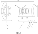
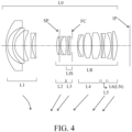
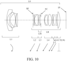
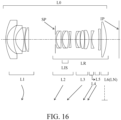
- FIGs. 1 , 4 , 7 , 10 , 13 , 16 and 19 are sectional views of zoom lenses L0 according to Examples 1 to 7 at a wide-angle end in an in-focus state at infinity, respectively.
- the zoom lens L0 according to each example is used for an image pickup apparatus such as a digital video camera, a digital still camera, a broadcasting camera, a silver salt film camera, a surveillance camera, and an in-vehicle camera.
- the zoom lens L0 according to each example is also applicable to a projection lens in a projector or the like.
- the zoom lens L0 includes a plurality of lens units.
- a lens unit is a group of lenses that move or stand still integrally during zooming. That is, in the zoom lens L0 according to each example, a distance between adjacent lens units is changed during zooming.
- the lens unit includes one or more lenses.
- the lens unit may include elements other than a lens unit, such as a diaphragm (aperture stop).
- the zoom lens L0 according to each example includes, in order from the object side to the image side, a first lens unit L1 having a negative refractive power, and a rear unit LR having a positive refractive power as a whole.
- the rear unit LR includes all lens units on the image side of the first lens unit L1. In the zoom lens L0 according to each example, a distance between the first lens unit L1 and the rear unit LR is changed during zooming.
- Li denotes an i-th lens unit (i is a natural number) counted from the object side among lens units included in the zoom lens L0.
- LN denotes a final lens unit closes to the image plane.
- SP denotes a diaphragm (aperture stop).
- the diaphragm SP is provided on the object side or inside of the second lens unit L2.
- FC denotes a sub-diaphragm (auxiliary diaphragm).
- IP denotes an image plane, and when the zoom lens L0 according to each example is used as an imaging optical system for a digital still camera or a digital video camera, an imaging plane of a solid-state image sensor (photoelectric conversion element) such as a CCD sensor and a CMOS sensor is disposed there. When the zoom lens L0 according to each example is used as an imaging optical system for a film-based camera, a photosensitive plane corresponding to a film plane is placed on the image plane IP.
- a solid-state image sensor photoelectric conversion element
- An arrow illustrated in the sectional view indicates a moving direction of the lens unit during zooming from the wide-angle end to the telephoto end or a moving direction of the lens unit during focusing from an infinity object to a short-distance object.
- a single lens unit is moved as a whole during focusing, but the present invention is not limited to this embodiment.
- only part of the lens unit may be moved, or the entire zoom lens L0 may be moved.
- the plurality of lenses may be moved in different trajectories.
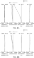
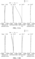
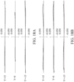
- FIGs. 2A, 2B , 5A, 5B , 8A, 8B , 11A, 11B , 14A, 14B , 17A, 17B , 20A, and 20B are longitudinal aberration diagrams of the zoom lenses L0 according to Examples 1 to 7, respectively.
- FIGs. 2A , 5A , 8A , 11A , 14A , 17A , and 20A are longitudinal aberration diagrams of the zoom lenses L0 at the wide-angle end
- FIGs. 2B , 5B , 8B , 11B , 14B , 17B , and 20B are longitudinal aberration diagrams of the zoom lenses L0 at the telephoto end.
- Fno denotes an F-number and indicates a spherical aberration amount for each of the d-line (wavelength 587.6 nm) and the g-line (wavelength 435.8 nm).
- M denotes an astigmatism amount on a meridional image plane
- S denotes an astigmatism amount on a sagittal image plane.
- the distortion diagram illustrates a distortion amount for the d-line.
- the chromatic aberration diagram illustrates a chromatic aberration amount for the g-line.
- ⁇ is a half imaging angle of view (°).
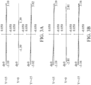
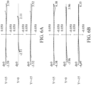
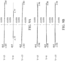
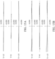
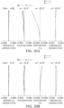
- FIGs. 3A, 3B , 6A, 6B , 9A, 9B , 12A, 12B , 15A, 15B , 18A, 18B , 21A, and 21B are lateral aberration diagrams of the zoom lens L0 according to each example during image stabilization by 0.3°.
- FIGs. 3A , 6A , 9A , 12A , 15A , 18A , and 21A are lateral aberration diagrams of the zoom lens L0 at the wide-angle end
- FIGs. 3B , 6B , 9B , 12B , 15B , 18B , and 21B are lateral aberration diagrams of the zoom lens L0 at the telephoto end.
- the unit of each axis is mm.
- Y is an image height (mm) made by evaluating the lateral aberration diagram.
- the zoom lens L0 according to each example is a so-called negative lead type zoom lens in which the first lens unit L1 has a negative refractive power.
- the negative lead type zoom lens is known as an effective configuration for widening the angle of view of the zoom lens.
- the rear unit LR includes a subunit (image stabilizing unit) LIS that moves in a direction having a component in a direction orthogonal to the optical axis during image stabilization. Thereby, a height of an off-axis light ray incident on the subunit LIS can be lowered, and the deterioration of the optical performance during the image stabilization can be suppressed.
- the subunit is a group of lenses whose constituent length (distance on the optical axis from a lens surface closest to the object to a lens surface closest to the image plane in the subunit) does not change during zooming.
- the subunit may be a single lens unit or part of the single lens unit.
- the first lens unit L1 includes, in order from the object side to the image side, three or more negative lenses. This configuration can secure a sufficiently wide angle of view (such as an angle of view of 100° or higher at the wide-angle end).
- the zoom lens L0 satisfies the following inequalities (conditional expressions) (1) and (2). ⁇ 20 ⁇ Dist_w ⁇ ⁇ 8 ⁇ 0.4 ⁇ f 1 / fLN ⁇ 0.7 where Dist_w is a distortion amount at a maximum image height in an in-focus state at infinity at the wide-angle end, f1 is a focal length of the first lens unit L1, and fLN is a focal length of the final lens unit LN.
- the inequality (1) defines a distortion amount of the maximum image height in the in-focus state at infinity at the wide-angle end.
- the maximum image height is a distance from the optical axis of an image point farthest from the optical axis among image points that can be imaged. If the distortion amount becomes excessively large beyond the upper limit in the inequality (1), a distortion amount in the equidistant projection method is too large, and the image quality in the periphery of the imaging plane significantly deteriorates during the image stabilization. Even in the lens shift image stabilization, an image stabilizing amount in the periphery of the imaging plane becomes insufficient. If the distortion amount becomes excessively small below the lower limit in the inequality (1), it becomes difficult to suppress the deterioration of the image quality in the periphery of the imaging plane during the electronic distortion correction.
- Dist_w % yp ⁇ y / y ⁇ 100 where y is an ideal image height in the central projection method, and yp is a real image height.
- the inequality (2) defines a ratio of the focal length of the first lens unit L1 to the focal length of the final lens unit LN. Satisfying the inequality (2) can achieve both the miniaturization and the high image quality. If the negative refractive power of the final lens unit LN becomes too strong beyond the upper limit in the inequality (2), and it becomes difficult to achieve the refractive power arrangement of the retrofocus and to widen the angle of view while ensuring the backfocus at the wide-angle end. If the positive refractive power of the final lens unit LN becomes too strong below the lower limit in the inequality (2), the refractive power arrangement of the retrofocus becomes strong, the asymmetry of the refractive power arrangement of the zoom lens L0 becomes remarkable, and it becomes difficult to correct the distortion at the wide-angle end. In addition, it becomes difficult to shorten the overall lens length of the zoom lens L0 (distance on the optical axis from the lens surface closest to the object to the image plane IP) at the wide-angle end.
- the zoom lens L0 according to each example can achieve both the wide angle of view and the miniaturization, and can maintain the high optical performance in the image stabilization.
- the numerical ranges of the inequalities (1) and (2) may be replaced with those of the following inequalities (1a) and (2a): ⁇ 19 ⁇ Dist_w ⁇ ⁇ 9 ⁇ 0.37 ⁇ f 1 / fLN ⁇ 0.60
- inequalities (1) and (2) may be replaced with those of the following inequalities (1b) and (2b): ⁇ 18 ⁇ Dist_w ⁇ ⁇ 10 ⁇ 0.34 ⁇ f 1 / fLN ⁇ 0.50
- the zoom lens L0 according to each example may satisfy one or more of the following inequalities (3) to (11), however the zoom lens according to the invention satisfies inequality (8): 1.0 ⁇ fLIS / ft ⁇ 4.0 0.00 ⁇ dIS / dt ⁇ 0.25 0.1 ⁇ dLIS / dR ⁇ 10.0 30 ⁇ ⁇ LIS ⁇ 70 ⁇ 1.0 ⁇ r 1 + r 2 / r 1 ⁇ r 2 ⁇ 0.6 ⁇ 2.2 ⁇ f 1 / skw ⁇ ⁇ 0.9 ⁇ 2.2 ⁇ f 1 / fw ⁇ 1.0 ⁇ 0.5 ⁇ fw / fLN ⁇ 0.3 ⁇ 1.5 ⁇ Ymax_w / f 1 ⁇ ⁇ 0.4
- fLIS is a focal length of the subunit LN.
- ft is a focal length of the zoom lens L0 at the telephoto end.
- dIS is a distance on the optical axis from a lens surface closest to the object in the rear unit LR to a lens surface closest to the object in the subunit LIS at the telephoto end.
- dt is an overall lens length of the zoom lens L0 at the telephoto end.
- dLIS is a distance on the optical axis from a lens surface closest to the object to a lens surface closest to the image plane in the subunit LIS.
- dR is a distance on the optical axis from a lens surface closest to the image plane in the subunit LIS to a lens surface closest to the object in a lens unit adjacent to and disposed on the image side of the subunit LIS at the wide-angle end.
- vLIS is an Abbe number of a lens having the shortest focal length in the subunit LIS.
- r1 is a radius of curvature of a lens surface closest to the object in the subunit LIS.
- r2 is a radius of curvature of a lens surface closest to the image plane in the subunit LIS.
- skw is a backfocus of the zoom lens L0 at the wide-angle end.
- fw is a focal length of the zoom lens L0 at the wide-angle end.
- Ymax_w is a maximum image height at the wide-angle end.
- the inequality (3) defines a refractive power of the subunit LIS. Satisfying the inequality (3) can reduce the outer diameter of the lens and suppress the aberration fluctuation during the image stabilization. If the refractive power of the subunit LIS becomes too weak beyond the upper limit in the inequality (3), the moving amount of the subunit LIS during the image stabilization becomes too large, and it becomes difficult to reduce the outer diameter of the lens. If the refractive power of the subunit LIS becomes too strong below the lower limit in the inequality (3), it becomes difficult to suppress fluctuations in the coma and curvature of field during the image stabilization.
- the inequality (4) defines a distance on the optical axis from a lens surface closest to the object in the rear unit LR to a lens surface closest to the object in the subunit LIS at the telephoto end. If the distance from the lens surface closest to the object in the rear unit LR to the lens surface closest to the object in the subunit LIS becomes too long beyond the upper limit in the inequality (4), it becomes difficult to suppress the fluctuation of the coma during the image stabilization. If the distance from the lens surface closest to the object in the rear unit LR to the lens surface closest to the object in the subunit LIS becomes too short below the lower limit in the inequality (4), it becomes difficult to properly arrange a driving unit that drives the subunit LIS or a driving unit that drives the diaphragm SP.
- the inequality (5) defines a ratio of the thickness of the subunit LIS to an distance (interval) in the subsequent group LR. If the subunit LIS becomes too thick beyond the upper limit in the inequality (5), the subunit LIS becomes heavy, the driving unit becomes large, and it becomes difficult to reduce the outer diameter of the lens. If the subunit LIS becomes too thin below the lower limit in the inequality (5), it becomes difficult to properly set a radius of curvature of the subunit LIS, and it becomes difficult to suppress fluctuations of the coma and the curvature of field during the image stabilization.
- the inequality (6) defines an Abbe number of the lens with the shortest focal length included in the subunit LIS.
- the Abbe number of the positive lens is defined
- the subunit LIS has a negative refractive power
- the Abbe number of the negative lens is defined. If the Abbe number is higher than the upper limit in the inequality (6), the refractive index becomes small, and it becomes difficult to suppress fluctuations in the coma during the image stabilization. If the Abbe number is lower than the lower limit in the inequality (6), it becomes difficult to suppress the fluctuation of the lateral chromatic aberration during the image stabilization.
- the inequality (7) defines a shape factor of the subunit LIS. If the value is higher the upper limit in the inequality (7) and the subunit LIS has a meniscus shape with a concave surface facing the image side, it becomes difficult to suppress the fluctuation of the curvature of field during the image stabilization. If the value is lower than the lower limit in the inequality (7) and the subunit LIS has a meniscus shape with a concave surface facing the object side, it becomes difficult to suppress the fluctuation of the coma during the image stabilization.
- the inequality (8) defines a ratio of the backfocus of the zoom lens L0 to the focal length of the first lens unit L1 at the wide-angle end. If the negative refractive power of the first lens unit L1 becomes too strong beyond the upper limit in the conditional inequality (8), the asymmetry of the refractive power arrangement of the zoom lens L0 becomes remarkable, and it becomes difficult to correct the distortion at the wide-angle end. If the negative refractive power of the first lens unit L1 becomes too weak below the lower limit in the inequality (8), it becomes difficult to achieve a wide angle of view exceeding 100° at the wide-angle end. In addition, the diameter of the front lens becomes large, and the outer diameter of the lens becomes large.
- the inequality (9) defines a focal length of the first lens unit L1. If the negative refractive power of the first lens unit L1 becomes too strong beyond the upper limit in the conditional inequality (9), the asymmetry of the refractive power arrangement of the zoom lens L0 becomes remarkable, and it becomes difficult to correct the distortion at the wide-angle end. If the refractive power of the first lens unit L1 becomes too weak below the lower limit in the inequality (9), it becomes difficult to achieve a wide angle of view exceeding 100° at the wide-angle end. In addition, the diameter of the front lens becomes large, and the outer diameter of the lens becomes large.
- the inequality (10) defines a focal length of the final lens unit LN. If the positive refractive power of the final lens unit LN becomes too strong beyond the upper limit in the conditional inequality (10), the refractive power arrangement of the retrofocus becomes strong, the asymmetry of the aberration of the refractive power arrangement of the zoom lens L0 becomes remarkable, and it becomes difficult to correct the distortion at the wide-angle end. In addition, it becomes difficult to shorten the overall lens length at the wide-angle end. If the negative refractive power of the final lens unit LN becomes too strong below the lower limit in the inequality (10), and it becomes difficult to achieve the refractive power arrangement of the retrofocus and to widen the angle of view while ensuring the backfocus at the wide-angle end.
- the inequality (11) defines a maximum image height that can be imaged at the wide-angle end. Satisfying the inequality (11) can make the zoom lens L0 smaller and lighter. If the maximum image height is too large beyond the upper limit, the light ray in a wider range than the desired angle of view will be imaged on the imaging plane, making excessively large the mechanical mechanism and optical system. As a result, it becomes difficult to reduce the size and weight of the zoom lens L0. If the maximum image height is too small below the lower limit, the angle of view will be narrower than the desired angle of view.
- the numerical ranges of the inequalities (3) to (11) may be replaced with those of the following inequalities (3a) to (11a): 1.1 ⁇ fLIS / ft ⁇ 3.5 0.00 ⁇ dIS / dt ⁇ 0.20 0.2 ⁇ dLIS / dR ⁇ 8.0 32 ⁇ vLIS ⁇ 68 ⁇ 0.8 ⁇ r 1 + r 2 / r 1 ⁇ r 2 ⁇ 0.5 ⁇ 2.1 ⁇ f 1 / skw ⁇ ⁇ 1.0 ⁇ 2.1 ⁇ f 1 / fw ⁇ ⁇ 1.1 ⁇ 0.40 ⁇ fw / fLN ⁇ 0.25 ⁇ 1.4 ⁇ Ymax_w / f 1 ⁇ ⁇ 0.5
- the numerical ranges of the inequalities (3) to (11) may be replaced with those of the following inequalities (3b) to (11b): 1.2 ⁇ fLIS / ft ⁇ 3.0 0.00 ⁇ dIS / dt ⁇ 0.15 0.3 ⁇ dLIS / dR ⁇ 6.0 34 ⁇ vLIS ⁇ 66 ⁇ 0.7 ⁇ r 1 + r 2 / r 1 ⁇ r 2 ⁇ 0.4 ⁇ 2.0 ⁇ f 1 / skw ⁇ ⁇ 1.1 ⁇ 2.0 ⁇ f 1 / fw ⁇ ⁇ 1.2 ⁇ 0.30 ⁇ fw / fLN ⁇ 0.20 ⁇ 1.3 ⁇ Ymax_w / f 1 ⁇ ⁇ 0.6
- the subunit LIS may include a positive lens and a negative lens. This configuration can effectively suppress fluctuations of the lateral chromatic aberration and the curvature of field during the image stabilization.
- the rear unit LR is disposed on the image side of the subunit LIS and includes two or more lens units whose distance changes during zooming. This configuration can realize a sufficient magnification variation ratio (such as twice) while ensuring a sufficient wide angle (such as an angle of view of 100° or higher at the wide-angle end).
- the rear unit LR is disposed on the image side of the subunit LIS and includes a focus unit that is moved during focusing.
- the image stabilizing unit disposed near the diaphragm and the focus unit disposed near the image plane can suppress the aberration fluctuations during the image stabilization and the aberration fluctuation during focusing at the same time.
- a distance between the first lens unit L1 and the rear unit LR may be the largest among distances between lens units included in the zoom lens L0. This configuration can increase a change in the distance between the first lens unit L1 and the rear unit LR during zooming, and it becomes easy to secure the zoom ratio.
- the first lens unit L1 may include a positive lens. This configuration can correct the chromatic aberration in the first lens unit L1, and can suppress the fluctuation of the chromatic aberration during zooming.
- the zoom lens L0 may have a memory that stores distortion correction data for correcting the distortion. This configuration can make small the zoom lens L0.
- the zoom lens L0 according to Example 1 includes, in order from the object side to the image side, a first lens unit L1 having a negative refractive power, and a rear unit LR having a negative refractive power as a whole.
- the rear unit LR includes, in order from the object side to the image side, a second lens unit L2 having a positive refractive power, a third lens unit L3 having a negative refractive power, a fourth lens unit L4 having a negative refractive power, and a fifth lens unit L5 having a positive refractive power.
- Part of the second lens unit L2 is a subunit LIS.
- the third lens unit L3 is a focus unit.
- the fifth lens unit L5 is a final lens unit LN.
- the first lens unit L1 is moved to the image side and then moved to the object side.
- the second lens unit L2 is moved toward the object while reducing a distance from the first lens unit L1.
- the third lens unit L3 moves toward the object while increasing a distance from the second lens unit L2.
- the fourth lens unit L4 moves toward the object while reducing a distance from the third lens unit L3.
- the fifth lens unit L5 moves to the object side while increasing a distance from the fourth lens unit L4, and then moved to the image side.
- the third lens unit L3 moves to the image side.
- the zoom lens L0 according to Example 2 includes, in order from the object side to the image side, a first lens unit L1 having a negative refractive power, and a rear unit LR having a negative refractive power as a whole.
- the rear unit LR includes, in order from the object side to the image side, a second lens unit L2 having a positive refractive power, a third lens unit L3 having a negative refractive power, a fourth lens unit L4 having a positive refractive power, a fifth lens unit L5 having a negative refractive power, and a sixth lens unit L6 having a positive refractive power.
- the third lens unit L3 is a subunit LIS.
- the fifth lens unit L5 is a focus unit.
- the sixth lens unit L6 is a final lens unit LN.
- the first lens unit L1 is moved to the image side.
- the second lens unit L2 is moved toward the object while reducing a distance from the first lens unit L1.
- the third lens unit L3 is moved toward the object while reducing a distance from the second lens unit L2.
- the fourth lens unit L4 is moved toward the object while reducing a distance from the third lens unit L3.
- the fifth lens unit L5 is moved toward the object while increasing a distance from the fourth lens unit L4.
- the sixth lens unit L6 is moved toward the object while increasing a distance from the fifth lens unit L5.
- the fifth lens unit L5 is moved to the image side.
- the zoom lens L0 according to Example 3 includes, in order from the object side to the image side, a first lens unit L1 having a negative refractive power, and a rear unit LR having a negative refractive power as a whole.
- the rear unit LR includes, in order from the object side to the image side, a second lens unit L2 having a positive refractive power, a third lens unit L3 having a positive refractive power, a fourth lens unit L4 having a negative refractive power, a fifth lens unit L5 having a negative refractive power, and a sixth lens unit L6 having a positive refractive power.
- Part of the second lens unit L2 is a subunit LIS.
- the fourth lens unit L4 is a focus unit.
- the sixth lens unit L6 is a final lens unit LN.
- the first lens unit L1 is moved to the image side and then moved to the object side.
- the second lens unit L2 is moved toward the object while reducing a distance from the first lens unit L1.
- the third lens unit L3 is moved toward the object while reducing a distance from the second lens unit L2.
- the fourth lens unit L4 is moved toward the object while increasing a distance from the third lens unit L3.
- the fifth lens unit L5 is moved toward the object while reducing a distance from the fourth lens unit L4.
- the sixth lens unit L6 is fixed (immovable). During focusing from an infinity object to a short-distance object, the fourth lens unit L4 is moved to the image side.
- the zoom lens L0 according to Example 4 includes, in order from the object side to the image side, a first lens unit L1 having a negative refractive power, and a rear unit LR having a negative refractive power as a whole.
- the rear unit LR includes, in order from the object side to the image side, a second lens unit L2 having a positive refractive power, a third lens unit L3 having a negative refractive power, a fourth lens unit L4 having a positive refractive power, a fifth lens unit L5 having a negative refractive power, a sixth lens unit L6 having a negative refractive power, and a seventh lens unit L7 having a positive refractive power.
- the third lens unit L3 is a subunit LIS.
- the fifth lens unit L5 is a focus unit.
- the seventh lens unit L7 is the final lens unit LN.
- the second lens unit L2 is moved toward the object while reducing a distance from the first lens unit L1.
- the third lens unit L3 is moved toward the object while increasing a distance from the second lens unit L2.
- the fourth lens unit L4 is moved toward the object while reducing a distance from the third lens unit L3.
- the fifth lens unit L5 is moved toward the object while increasing a distance from the fourth lens unit L4.
- the sixth lens unit L6 is moved toward the object while reducing a distance from the fifth lens unit L5.
- the seventh lens unit L7 is fixed. During focusing from an infinity object to a short-distance object, the fifth lens unit L5 is moved to the image side.
- the zoom lens L0 according to Example 5 includes, in order from the object side to the image side, a first lens unit L1 having a negative refractive power, and a rear unit LR having a negative refractive power as a whole.
- the rear unit LR includes, in order from the object side to the image side, a second lens unit L2 having a positive refractive power, a third lens unit L3 having a negative refractive power, a fourth lens unit L4 having a negative refractive power, and a fifth lens unit L5 having a positive refractive power.
- Part of the second lens unit L2 is a subunit LIS.
- the third lens unit L3 is a focus unit.
- the fifth lens unit L5 is a final lens unit LN.
- the first lens unit L1 is moved to the image side and then moved to the object side.
- the second lens unit L2 is moved toward the object while reducing a distance from the first lens unit L1.
- the third lens unit L3 moves toward the object while increasing a distance from the second lens unit L2.
- the fourth lens unit L4 is moved toward the object while reducing a distance from the third lens unit L3.
- the fifth lens unit L5 is moved to the image side while increasing a distance from the fourth lens unit L4.
- the third lens unit L3 is moved to the image side.
- the zoom lens L0 according to Example 6 includes, in order from the object side to the image side, a first lens unit L1 having a negative refractive power, and a rear unit LR having a negative refractive power as a whole.
- the rear unit LR includes, in order from the object side to the image side, a second lens unit L2 having a positive refractive power, a third lens unit L3 having a positive refractive power, a fourth lens unit L4 having a negative refractive power, a fifth lens unit L5 having a negative refractive power, and a sixth lens unit L6 having a positive refractive power.
- Part of the second lens unit L2 is a subunit LIS.
- the fourth lens unit L4 is a focus unit.
- the sixth lens unit L6 is a final lens unit LN.
- the first lens unit L1 is moved to the image side and then to the object side.
- the second lens unit L2 is moved toward the object while reducing a distance from the first lens unit L1.
- the third lens unit L3 is moved toward the object while reducing a distance from the second lens unit L2.
- the fourth lens unit L4 is moved toward the object while increasing a distance from the third lens unit L3.
- the fifth lens unit L5 is moved toward the object while reducing a distance from the fourth lens unit L4.
- the sixth lens unit L6 is fixed. During focusing from an infinity object to a short-distance object, the fourth lens unit L4 is moved to the image side.
- the first lens unit L1 is moved to the image side and then moved to the object side.
- the second lens unit L2 is moved toward the object while reducing a distance from the first lens unit L1.
- the third lens unit L3 is moved toward the object while increasing a distance from the second lens unit L2.
- the fourth lens unit L4 is moved toward the object while reducing a distance from the third lens unit L3.
- the third lens unit L3 is moved to the image side.
- r denotes a radius of curvature of each optical surface
- d (mm) denotes an on-axis distance (distance on the optical axis) between an m-th surface and an (m+1)-th surface, where m is the number of a surface counted from the light incident side.
- nd denotes a refractive index of each optical element for the d-line
- vd denotes an Abbe number of an optical element.
- ⁇ d Nd ⁇ 1 / NF ⁇ NC
- Nd, NF, and NC are refractive indexes for the d-line (587.6 nm), F-line (486.1 nm), C-line (656.3 nm), and g-line (wavelength 435.8 nm) in the Fraunhofer lines.
- all values of d, a focal length (mm), an F-number, and a half angle of view (degree) are set when the zoom lens L0 according to each example focuses on an infinity object.
- a "backfocus” is a distance on the optical axis from the final lens surface (lens surface closest to the image plane) to a paraxial image plane and is converted into an air equivalent length.
- the “overall lens length” is a length obtained by adding the backfocus to a distance on the optical axis from the frontmost surface (lens surface closest to the object) to the final surface in the zoom lens L0.
- the “lens unit” may include one or more lenses.
- optical surface is an aspherical surface
- an asterisk * is attached to the right side of the surface number.
- X is a displacement amount from a surface apex in the optical axis direction
- h is a height from the optical axis in the direction orthogonal to the optical axis
- R is a paraxial radius of curvature
- K is a conical constant
- A4, A6, A8, A10, and A12 are aspherical coefficients of each order.
- "e ⁇ XX" in each aspherical coefficient means " ⁇ 10 ⁇ XX .”
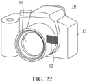
- reference numeral 10 denotes a camera body
- reference numeral 11 denotes an imaging optical system that includes any one of the zoom lenses L0 according to Examples 1 to 7.
- Reference numeral 12 denotes a solid-state image sensor (photoelectric conversion element) such as a CCD sensor and a CMOS sensor, which is built in the camera body, receives an optical image formed by the imaging optical system 11, and performs a photoelectric conversion.
- the camera body 10 may be a so-called single-lens reflex camera having a quick turn mirror, or a so-called mirrorless camera having no quick turn mirror.
- the zoom lens L0 according to each example thus applied to an image pickup apparatus such as a digital still camera can provide an image pickup apparatus having a compact lens.
- Each example can provide a zoom lens and an image pickup apparatus having the same, each of which can maintain a high optical performance in image stabilization while achieving both a wide angle of view and miniaturization.
Landscapes
- Physics & Mathematics (AREA)
- General Physics & Mathematics (AREA)
- Optics & Photonics (AREA)
- Nonlinear Science (AREA)
- Engineering & Computer Science (AREA)
- Multimedia (AREA)
- Signal Processing (AREA)
- Lenses (AREA)
Description
- The present invention relates to a zoom lens, which is suitable for a digital video camera, a digital still camera, a broadcasting camera, a film-based camera, a surveillance camera, an in-vehicle camera, and the like.
- A lens shift type image stabilizing mechanism that shifts part of an optical system in a direction orthogonal to an optical axis and a sensor shift type image stabilizing mechanism that shifts an image sensor in that direction have conventionally been known as an image stabilizing means. Japanese Patent Laid-Open No. ("
JP") 2019-215565 - In the zoom lens disclosed in
JP 2019-215565 - When an ultra-wide-angle zoom lens with an angle of view exceeding 100° is used, the sensor shift type image stabilizing mechanism is often used because a large correction amount is available with a small shift amount. Since a moving amount of an image point to a change in an incident angle of a light ray incident on an optical system using the central projection method is not uniform on the imaging plane, a large image blur amount remains in the periphery of the imaging plane even when the image stabilization is made at the center of the imaging plane in a zoom lens that suppresses the distortion by the central projection method. If the projection method is brought to the equidistant projection method having no difference in image blur in order to suppress the image blur in the periphery of the imaging plane, the image will be greatly distorted and thus such a zoom lens is often used with an image pickup apparatus that has an electronic distortion correcting function that corrects the distortion in image processing. However, if the distortion in the central projection method is excessively generated, the image quality in the periphery of the imaging plane deteriorates due to the electronic distortion correction. It is therefore necessary to properly set the distortion in the central projection method in order to suppress the image quality deterioration in the periphery of the imaging plane by the image stabilization and the electronic distortion correction.
The lens shift type image stabilizing mechanism can suppress the image blur in the periphery of the imaging plane because the image stabilizing sensitivity (ratio of an image stabilizing amount to a unit moving amount of the image stabilizing unit) in the periphery of the imaging plane is higher than that at the center of the imaging plane. Therefore, it is desirable to mount the lens shift type image stabilizing mechanism on the ultra-wide-angle zoom lens.
US 2017/0068079 A1 relates to a zoom lens with a front unit having a negative refractive power and a rear unit having a positive refractive power which includes an aperture stop, wherein at the time of zooming from the wide angle end to the telephoto end, the distance between the front unit and the rear unit changes. - The present invention provides a zoom lens and an image pickup apparatus having the same, each of which can maintain a high optical performance in image stabilization while achieving both a wide angle of view and miniaturization.
- The present invention in its first aspect provides a zoom lens as specified in claims 1 to 16.
- The present invention in its second aspect provides a zoom lens as specified in claim 17.
- Further features of the present invention will become apparent from the following description of exemplary embodiments with reference to the attached drawings.
-
-
FIG. 1 is a sectional view of a zoom lens according to Example 1. -
FIGs. 2A and 2B are longitudinal aberration diagrams of the zoom lens at the wide-angle end and at the telephoto end in Example 1, respectively. -
FIGs. 3A and 3B are lateral aberration diagrams of the zoom lens at the wide-angle end and at the telephoto end in the image stabilization in Example 1, respectively. -
FIG. 4 is a sectional view of a zoom lens according to Example 2. -
FIGs. 5A and 5B are longitudinal aberration diagrams of the zoom lens at the wide-angle end and at the telephoto end in Example 2, respectively. -
FIGs. 6A and 6B are lateral aberration diagrams of the zoom lens at the wide-angle end and at the telephoto end in the image stabilization in Example 2, respectively. -
FIG. 7 is a sectional view of a zoom lens according to Example 3. -
FIGs. 8A and 8B are longitudinal aberration diagrams of the zoom lens at the wide-angle end and at the telephoto end in Example 3, respectively. -
FIGs. 9A and 9B are lateral aberration diagrams of the zoom lens at the wide-angle end and at the telephoto end in the image stabilization in Example 3, respectively. -
FIG. 10 is a sectional view of a zoom lens according to Example 4. -
FIGs. 11A and 11B are longitudinal aberration diagrams of the zoom lens at the wide-angle end and at the telephoto end in Example 4, respectively. -
FIGs. 12A and 12B are lateral aberration diagrams of the zoom lens at the wide-angle end and at the telephoto end in the image stabilization in Example 4, respectively. -
FIG. 13 is a sectional view of a zoom lens according to Example 5. -
FIGs. 14A and 14B are longitudinal aberration diagrams of the zoom lens at the wide-angle end and at the telephoto end in Example 5, respectively. -
FIGs. 15A and 15B are lateral aberration diagrams of the zoom lens at the wide-angle end and at the telephoto end in the image stabilization in Example 5, respectively. -
FIG. 16 is a sectional view of a zoom lens according to Example 6. -
FIGs. 17A and 17B are longitudinal aberration diagrams of the zoom lens at the wide-angle end and at the telephoto end in Example 6, respectively. -
FIGs. 18A and 18B are lateral aberration diagrams of the zoom lens at the wide-angle end and at the telephoto end in the image stabilization in Example 6, respectively. -
FIG. 19 is a sectional view of a zoom lens according to Example 7. -
FIGs. 20A and 20B are longitudinal aberration diagrams of the zoom lens at the wide-angle end and at the telephoto end in Example 7, respectively. -
FIGs. 21A and 21B are lateral aberration diagrams of the zoom lens at the wide-angle end and at the telephoto end in the image stabilization in Example 7, respectively. -
FIG. 22 is a schematic view of an image pickup apparatus. - Referring now to the accompanying drawings, a detailed description will be given of embodiments according to the present invention. Corresponding elements in respective figures will be designated by the same reference numerals, and a duplicate description thereof will be omitted.
-
FIGs. 1 ,4 ,7 ,10 ,13 ,16 and19 are sectional views of zoom lenses L0 according to Examples 1 to 7 at a wide-angle end in an in-focus state at infinity, respectively. The zoom lens L0 according to each example is used for an image pickup apparatus such as a digital video camera, a digital still camera, a broadcasting camera, a silver salt film camera, a surveillance camera, and an in-vehicle camera. The zoom lens L0 according to each example is also applicable to a projection lens in a projector or the like. - In each sectional view, a left side is an object side (front), and a right side is an image side (rear). The zoom lens L0 according to each example includes a plurality of lens units. In this specification, a lens unit is a group of lenses that move or stand still integrally during zooming. That is, in the zoom lens L0 according to each example, a distance between adjacent lens units is changed during zooming. The lens unit includes one or more lenses. The lens unit may include elements other than a lens unit, such as a diaphragm (aperture stop).
- The zoom lens L0 according to each example includes, in order from the object side to the image side, a first lens unit L1 having a negative refractive power, and a rear unit LR having a positive refractive power as a whole. The rear unit LR includes all lens units on the image side of the first lens unit L1. In the zoom lens L0 according to each example, a distance between the first lens unit L1 and the rear unit LR is changed during zooming.
- In each sectional view, Li denotes an i-th lens unit (i is a natural number) counted from the object side among lens units included in the zoom lens L0. LN denotes a final lens unit closes to the image plane.
- SP denotes a diaphragm (aperture stop). The diaphragm SP is provided on the object side or inside of the second lens unit L2. FC denotes a sub-diaphragm (auxiliary diaphragm). IP denotes an image plane, and when the zoom lens L0 according to each example is used as an imaging optical system for a digital still camera or a digital video camera, an imaging plane of a solid-state image sensor (photoelectric conversion element) such as a CCD sensor and a CMOS sensor is disposed there. When the zoom lens L0 according to each example is used as an imaging optical system for a film-based camera, a photosensitive plane corresponding to a film plane is placed on the image plane IP.
- An arrow illustrated in the sectional view indicates a moving direction of the lens unit during zooming from the wide-angle end to the telephoto end or a moving direction of the lens unit during focusing from an infinity object to a short-distance object. In each example, a single lens unit is moved as a whole during focusing, but the present invention is not limited to this embodiment. During focusing, only part of the lens unit may be moved, or the entire zoom lens L0 may be moved. During focusing, the plurality of lenses may be moved in different trajectories.
-
FIGs. 2A, 2B ,5A, 5B ,8A, 8B ,11A, 11B ,14A, 14B ,17A, 17B ,20A, and 20B are longitudinal aberration diagrams of the zoom lenses L0 according to Examples 1 to 7, respectively. In each longitudinal aberration diagram,FIGs. 2A ,5A ,8A ,11A ,14A ,17A , and20A are longitudinal aberration diagrams of the zoom lenses L0 at the wide-angle end, andFIGs. 2B ,5B ,8B ,11B ,14B ,17B , and20B are longitudinal aberration diagrams of the zoom lenses L0 at the telephoto end. In the spherical aberration diagram, Fno denotes an F-number and indicates a spherical aberration amount for each of the d-line (wavelength 587.6 nm) and the g-line (wavelength 435.8 nm). In the astigmatism diagram, M denotes an astigmatism amount on a meridional image plane, and S denotes an astigmatism amount on a sagittal image plane. The distortion diagram illustrates a distortion amount for the d-line. The chromatic aberration diagram illustrates a chromatic aberration amount for the g-line. ω is a half imaging angle of view (°). -
FIGs. 3A, 3B ,6A, 6B ,9A, 9B ,12A, 12B ,15A, 15B ,18A, 18B ,21A, and 21B are lateral aberration diagrams of the zoom lens L0 according to each example during image stabilization by 0.3°. In each lateral aberration diagram,FIGs. 3A ,6A ,9A ,12A ,15A ,18A , and21A are lateral aberration diagrams of the zoom lens L0 at the wide-angle end, andFIGs. 3B ,6B ,9B ,12B ,15B ,18B , and21B are lateral aberration diagrams of the zoom lens L0 at the telephoto end. The unit of each axis is mm. Y is an image height (mm) made by evaluating the lateral aberration diagram. - Next follows a description of characteristic configurations of the zoom lens L0 according to each example.
- The zoom lens L0 according to each example is a so-called negative lead type zoom lens in which the first lens unit L1 has a negative refractive power. The negative lead type zoom lens is known as an effective configuration for widening the angle of view of the zoom lens.
- The rear unit LR includes a subunit (image stabilizing unit) LIS that moves in a direction having a component in a direction orthogonal to the optical axis during image stabilization. Thereby, a height of an off-axis light ray incident on the subunit LIS can be lowered, and the deterioration of the optical performance during the image stabilization can be suppressed. In this specification, the subunit is a group of lenses whose constituent length (distance on the optical axis from a lens surface closest to the object to a lens surface closest to the image plane in the subunit) does not change during zooming. The subunit may be a single lens unit or part of the single lens unit.
- The first lens unit L1 includes, in order from the object side to the image side, three or more negative lenses. This configuration can secure a sufficiently wide angle of view (such as an angle of view of 100° or higher at the wide-angle end).
- The zoom lens L0 according to each example satisfies the following inequalities (conditional expressions) (1) and (2).


- The inequality (1) defines a distortion amount of the maximum image height in the in-focus state at infinity at the wide-angle end. The maximum image height is a distance from the optical axis of an image point farthest from the optical axis among image points that can be imaged. If the distortion amount becomes excessively large beyond the upper limit in the inequality (1), a distortion amount in the equidistant projection method is too large, and the image quality in the periphery of the imaging plane significantly deteriorates during the image stabilization. Even in the lens shift image stabilization, an image stabilizing amount in the periphery of the imaging plane becomes insufficient. If the distortion amount becomes excessively small below the lower limit in the inequality (1), it becomes difficult to suppress the deterioration of the image quality in the periphery of the imaging plane during the electronic distortion correction.
- The distortion amount Dist_w [%] at an arbitrary image height at the wide-angle end is defined by the following inequality:

- The ideal image height y in the central projection method is defined by the following inequality:
- The inequality (2) defines a ratio of the focal length of the first lens unit L1 to the focal length of the final lens unit LN. Satisfying the inequality (2) can achieve both the miniaturization and the high image quality. If the negative refractive power of the final lens unit LN becomes too strong beyond the upper limit in the inequality (2), and it becomes difficult to achieve the refractive power arrangement of the retrofocus and to widen the angle of view while ensuring the backfocus at the wide-angle end. If the positive refractive power of the final lens unit LN becomes too strong below the lower limit in the inequality (2), the refractive power arrangement of the retrofocus becomes strong, the asymmetry of the refractive power arrangement of the zoom lens L0 becomes remarkable, and it becomes difficult to correct the distortion at the wide-angle end. In addition, it becomes difficult to shorten the overall lens length of the zoom lens L0 (distance on the optical axis from the lens surface closest to the object to the image plane IP) at the wide-angle end.
- Due to the above configuration, the zoom lens L0 according to each example can achieve both the wide angle of view and the miniaturization, and can maintain the high optical performance in the image stabilization.
- The numerical ranges of the inequalities (1) and (2) may be replaced with those of the following inequalities (1a) and (2a):


- The numerical ranges of inequalities (1) and (2) may be replaced with those of the following inequalities (1b) and (2b):


- Next follows a description of conditions which the zoom lens L0 according to each example may satisfy. The zoom lens L0 according to each example may satisfy one or more of the following inequalities (3) to (11), however the zoom lens according to the invention satisfies inequality (8):


- Here, fLIS is a focal length of the subunit LN. ft is a focal length of the zoom lens L0 at the telephoto end. dIS is a distance on the optical axis from a lens surface closest to the object in the rear unit LR to a lens surface closest to the object in the subunit LIS at the telephoto end. dt is an overall lens length of the zoom lens L0 at the telephoto end. dLIS is a distance on the optical axis from a lens surface closest to the object to a lens surface closest to the image plane in the subunit LIS. dR is a distance on the optical axis from a lens surface closest to the image plane in the subunit LIS to a lens surface closest to the object in a lens unit adjacent to and disposed on the image side of the subunit LIS at the wide-angle end. vLIS is an Abbe number of a lens having the shortest focal length in the subunit LIS. r1 is a radius of curvature of a lens surface closest to the object in the subunit LIS. r2 is a radius of curvature of a lens surface closest to the image plane in the subunit LIS. skw is a backfocus of the zoom lens L0 at the wide-angle end. fw is a focal length of the zoom lens L0 at the wide-angle end. Ymax_w is a maximum image height at the wide-angle end.
- The inequality (3) defines a refractive power of the subunit LIS. Satisfying the inequality (3) can reduce the outer diameter of the lens and suppress the aberration fluctuation during the image stabilization. If the refractive power of the subunit LIS becomes too weak beyond the upper limit in the inequality (3), the moving amount of the subunit LIS during the image stabilization becomes too large, and it becomes difficult to reduce the outer diameter of the lens. If the refractive power of the subunit LIS becomes too strong below the lower limit in the inequality (3), it becomes difficult to suppress fluctuations in the coma and curvature of field during the image stabilization.
- The inequality (4) defines a distance on the optical axis from a lens surface closest to the object in the rear unit LR to a lens surface closest to the object in the subunit LIS at the telephoto end. If the distance from the lens surface closest to the object in the rear unit LR to the lens surface closest to the object in the subunit LIS becomes too long beyond the upper limit in the inequality (4), it becomes difficult to suppress the fluctuation of the coma during the image stabilization. If the distance from the lens surface closest to the object in the rear unit LR to the lens surface closest to the object in the subunit LIS becomes too short below the lower limit in the inequality (4), it becomes difficult to properly arrange a driving unit that drives the subunit LIS or a driving unit that drives the diaphragm SP.
- The inequality (5) defines a ratio of the thickness of the subunit LIS to an distance (interval) in the subsequent group LR. If the subunit LIS becomes too thick beyond the upper limit in the inequality (5), the subunit LIS becomes heavy, the driving unit becomes large, and it becomes difficult to reduce the outer diameter of the lens. If the subunit LIS becomes too thin below the lower limit in the inequality (5), it becomes difficult to properly set a radius of curvature of the subunit LIS, and it becomes difficult to suppress fluctuations of the coma and the curvature of field during the image stabilization.
- The inequality (6) defines an Abbe number of the lens with the shortest focal length included in the subunit LIS. When the subunit LIS has a positive refractive power, the Abbe number of the positive lens is defined, and when the subunit LIS has a negative refractive power, the Abbe number of the negative lens is defined. If the Abbe number is higher than the upper limit in the inequality (6), the refractive index becomes small, and it becomes difficult to suppress fluctuations in the coma during the image stabilization. If the Abbe number is lower than the lower limit in the inequality (6), it becomes difficult to suppress the fluctuation of the lateral chromatic aberration during the image stabilization.
- The inequality (7) defines a shape factor of the subunit LIS. If the value is higher the upper limit in the inequality (7) and the subunit LIS has a meniscus shape with a concave surface facing the image side, it becomes difficult to suppress the fluctuation of the curvature of field during the image stabilization. If the value is lower than the lower limit in the inequality (7) and the subunit LIS has a meniscus shape with a concave surface facing the object side, it becomes difficult to suppress the fluctuation of the coma during the image stabilization.
- The inequality (8) defines a ratio of the backfocus of the zoom lens L0 to the focal length of the first lens unit L1 at the wide-angle end. If the negative refractive power of the first lens unit L1 becomes too strong beyond the upper limit in the conditional inequality (8), the asymmetry of the refractive power arrangement of the zoom lens L0 becomes remarkable, and it becomes difficult to correct the distortion at the wide-angle end. If the negative refractive power of the first lens unit L1 becomes too weak below the lower limit in the inequality (8), it becomes difficult to achieve a wide angle of view exceeding 100° at the wide-angle end. In addition, the diameter of the front lens becomes large, and the outer diameter of the lens becomes large.
- The inequality (9) defines a focal length of the first lens unit L1. If the negative refractive power of the first lens unit L1 becomes too strong beyond the upper limit in the conditional inequality (9), the asymmetry of the refractive power arrangement of the zoom lens L0 becomes remarkable, and it becomes difficult to correct the distortion at the wide-angle end. If the refractive power of the first lens unit L1 becomes too weak below the lower limit in the inequality (9), it becomes difficult to achieve a wide angle of view exceeding 100° at the wide-angle end. In addition, the diameter of the front lens becomes large, and the outer diameter of the lens becomes large.
- The inequality (10) defines a focal length of the final lens unit LN. If the positive refractive power of the final lens unit LN becomes too strong beyond the upper limit in the conditional inequality (10), the refractive power arrangement of the retrofocus becomes strong, the asymmetry of the aberration of the refractive power arrangement of the zoom lens L0 becomes remarkable, and it becomes difficult to correct the distortion at the wide-angle end. In addition, it becomes difficult to shorten the overall lens length at the wide-angle end. If the negative refractive power of the final lens unit LN becomes too strong below the lower limit in the inequality (10), and it becomes difficult to achieve the refractive power arrangement of the retrofocus and to widen the angle of view while ensuring the backfocus at the wide-angle end.
- The inequality (11) defines a maximum image height that can be imaged at the wide-angle end. Satisfying the inequality (11) can make the zoom lens L0 smaller and lighter. If the maximum image height is too large beyond the upper limit, the light ray in a wider range than the desired angle of view will be imaged on the imaging plane, making excessively large the mechanical mechanism and optical system. As a result, it becomes difficult to reduce the size and weight of the zoom lens L0. If the maximum image height is too small below the lower limit, the angle of view will be narrower than the desired angle of view.
- The numerical ranges of the inequalities (3) to (11) may be replaced with those of the following inequalities (3a) to (11a):


- The numerical ranges of the inequalities (3) to (11) may be replaced with those of the following inequalities (3b) to (11b):


- Next follows a description of a configuration that the zoom lens L0 according to each example may satisfy.
- The subunit LIS may include a positive lens and a negative lens. This configuration can effectively suppress fluctuations of the lateral chromatic aberration and the curvature of field during the image stabilization.
- The rear unit LR is disposed on the image side of the subunit LIS and includes two or more lens units whose distance changes during zooming. This configuration can realize a sufficient magnification variation ratio (such as twice) while ensuring a sufficient wide angle (such as an angle of view of 100° or higher at the wide-angle end).
- The rear unit LR is disposed on the image side of the subunit LIS and includes a focus unit that is moved during focusing. The image stabilizing unit disposed near the diaphragm and the focus unit disposed near the image plane can suppress the aberration fluctuations during the image stabilization and the aberration fluctuation during focusing at the same time.
- At the wide-angle end, a distance between the first lens unit L1 and the rear unit LR may be the largest among distances between lens units included in the zoom lens L0. This configuration can increase a change in the distance between the first lens unit L1 and the rear unit LR during zooming, and it becomes easy to secure the zoom ratio.
- The first lens unit L1 may include a positive lens. This configuration can correct the chromatic aberration in the first lens unit L1, and can suppress the fluctuation of the chromatic aberration during zooming.
- The zoom lens L0 may have a memory that stores distortion correction data for correcting the distortion. This configuration can make small the zoom lens L0.
- A detailed description will now be given of the zoom lens L0 according to each example.
- The zoom lens L0 according to Example 1 includes, in order from the object side to the image side, a first lens unit L1 having a negative refractive power, and a rear unit LR having a negative refractive power as a whole. The rear unit LR includes, in order from the object side to the image side, a second lens unit L2 having a positive refractive power, a third lens unit L3 having a negative refractive power, a fourth lens unit L4 having a negative refractive power, and a fifth lens unit L5 having a positive refractive power. Part of the second lens unit L2 is a subunit LIS. The third lens unit L3 is a focus unit. The fifth lens unit L5 is a final lens unit LN. During zooming from the wide-angle end to the telephoto end, the first lens unit L1 is moved to the image side and then moved to the object side. The second lens unit L2 is moved toward the object while reducing a distance from the first lens unit L1. The third lens unit L3 moves toward the object while increasing a distance from the second lens unit L2. The fourth lens unit L4 moves toward the object while reducing a distance from the third lens unit L3. The fifth lens unit L5 moves to the object side while increasing a distance from the fourth lens unit L4, and then moved to the image side. During focusing from an infinity object to a short-distance object, the third lens unit L3 moves to the image side.
- The zoom lens L0 according to Example 2 includes, in order from the object side to the image side, a first lens unit L1 having a negative refractive power, and a rear unit LR having a negative refractive power as a whole. The rear unit LR includes, in order from the object side to the image side, a second lens unit L2 having a positive refractive power, a third lens unit L3 having a negative refractive power, a fourth lens unit L4 having a positive refractive power, a fifth lens unit L5 having a negative refractive power, and a sixth lens unit L6 having a positive refractive power. The third lens unit L3 is a subunit LIS. The fifth lens unit L5 is a focus unit. The sixth lens unit L6 is a final lens unit LN. During zooming from the wide-angle end to the telephoto end, the first lens unit L1 is moved to the image side. The second lens unit L2 is moved toward the object while reducing a distance from the first lens unit L1. The third lens unit L3 is moved toward the object while reducing a distance from the second lens unit L2. The fourth lens unit L4 is moved toward the object while reducing a distance from the third lens unit L3. The fifth lens unit L5 is moved toward the object while increasing a distance from the fourth lens unit L4. The sixth lens unit L6 is moved toward the object while increasing a distance from the fifth lens unit L5. During focusing from an infinity object to a short-distance object, the fifth lens unit L5 is moved to the image side.
- The zoom lens L0 according to Example 3 includes, in order from the object side to the image side, a first lens unit L1 having a negative refractive power, and a rear unit LR having a negative refractive power as a whole. The rear unit LR includes, in order from the object side to the image side, a second lens unit L2 having a positive refractive power, a third lens unit L3 having a positive refractive power, a fourth lens unit L4 having a negative refractive power, a fifth lens unit L5 having a negative refractive power, and a sixth lens unit L6 having a positive refractive power. Part of the second lens unit L2 is a subunit LIS. The fourth lens unit L4 is a focus unit. The sixth lens unit L6 is a final lens unit LN. During zooming from the wide-angle end to the telephoto end, the first lens unit L1 is moved to the image side and then moved to the object side. The second lens unit L2 is moved toward the object while reducing a distance from the first lens unit L1. The third lens unit L3 is moved toward the object while reducing a distance from the second lens unit L2. The fourth lens unit L4 is moved toward the object while increasing a distance from the third lens unit L3. The fifth lens unit L5 is moved toward the object while reducing a distance from the fourth lens unit L4. The sixth lens unit L6 is fixed (immovable). During focusing from an infinity object to a short-distance object, the fourth lens unit L4 is moved to the image side.
- The zoom lens L0 according to Example 4 includes, in order from the object side to the image side, a first lens unit L1 having a negative refractive power, and a rear unit LR having a negative refractive power as a whole. The rear unit LR includes, in order from the object side to the image side, a second lens unit L2 having a positive refractive power, a third lens unit L3 having a negative refractive power, a fourth lens unit L4 having a positive refractive power, a fifth lens unit L5 having a negative refractive power, a sixth lens unit L6 having a negative refractive power, and a seventh lens unit L7 having a positive refractive power. The third lens unit L3 is a subunit LIS. The fifth lens unit L5 is a focus unit. The seventh lens unit L7 is the final lens unit LN. During zooming from the wide-angle end to the telephoto end, the first lens unit L1 is moved to the image side and then moved to the object side. The second lens unit L2 is moved toward the object while reducing a distance from the first lens unit L1. The third lens unit L3 is moved toward the object while increasing a distance from the second lens unit L2. The fourth lens unit L4 is moved toward the object while reducing a distance from the third lens unit L3. The fifth lens unit L5 is moved toward the object while increasing a distance from the fourth lens unit L4. The sixth lens unit L6 is moved toward the object while reducing a distance from the fifth lens unit L5. The seventh lens unit L7 is fixed. During focusing from an infinity object to a short-distance object, the fifth lens unit L5 is moved to the image side.
- The zoom lens L0 according to Example 5 includes, in order from the object side to the image side, a first lens unit L1 having a negative refractive power, and a rear unit LR having a negative refractive power as a whole. The rear unit LR includes, in order from the object side to the image side, a second lens unit L2 having a positive refractive power, a third lens unit L3 having a negative refractive power, a fourth lens unit L4 having a negative refractive power, and a fifth lens unit L5 having a positive refractive power. Part of the second lens unit L2 is a subunit LIS. The third lens unit L3 is a focus unit. The fifth lens unit L5 is a final lens unit LN. During zooming from the wide-angle end to the telephoto end, the first lens unit L1 is moved to the image side and then moved to the object side. The second lens unit L2 is moved toward the object while reducing a distance from the first lens unit L1. The third lens unit L3 moves toward the object while increasing a distance from the second lens unit L2. The fourth lens unit L4 is moved toward the object while reducing a distance from the third lens unit L3. The fifth lens unit L5 is moved to the image side while increasing a distance from the fourth lens unit L4. During focusing from an infinity object to a short-distance object, the third lens unit L3 is moved to the image side.
- The zoom lens L0 according to Example 6 includes, in order from the object side to the image side, a first lens unit L1 having a negative refractive power, and a rear unit LR having a negative refractive power as a whole. The rear unit LR includes, in order from the object side to the image side, a second lens unit L2 having a positive refractive power, a third lens unit L3 having a positive refractive power, a fourth lens unit L4 having a negative refractive power, a fifth lens unit L5 having a negative refractive power, and a sixth lens unit L6 having a positive refractive power. Part of the second lens unit L2 is a subunit LIS. The fourth lens unit L4 is a focus unit. The sixth lens unit L6 is a final lens unit LN. During zooming from the wide-angle end to the telephoto end, the first lens unit L1 is moved to the image side and then to the object side. The second lens unit L2 is moved toward the object while reducing a distance from the first lens unit L1. The third lens unit L3 is moved toward the object while reducing a distance from the second lens unit L2. The fourth lens unit L4 is moved toward the object while increasing a distance from the third lens unit L3. The fifth lens unit L5 is moved toward the object while reducing a distance from the fourth lens unit L4. The sixth lens unit L6 is fixed. During focusing from an infinity object to a short-distance object, the fourth lens unit L4 is moved to the image side.
- The zoom lens according to Example 7 includes, in order from the object side to the image side, a first lens unit L1 having a negative refractive power, and a rear unit LR having a negative refractive power as a whole. The rear unit LR includes, in order from the object side to the image side, a second lens unit L2 having a positive refractive power, a third lens unit L3 having a negative refractive power, and a fourth lens unit L4 having a negative refractive power. Part of the second lens unit L2 is a subunit LIS. The third lens unit L3 is a focus unit. The fourth lens unit L4 is a final lens unit LN. During zooming from the wide-angle end to the telephoto end, the first lens unit L1 is moved to the image side and then moved to the object side. The second lens unit L2 is moved toward the object while reducing a distance from the first lens unit L1. The third lens unit L3 is moved toward the object while increasing a distance from the second lens unit L2. The fourth lens unit L4 is moved toward the object while reducing a distance from the third lens unit L3. During focusing from an infinity object to a short-distance object, the third lens unit L3 is moved to the image side.
- Numerical examples 1 to 7 corresponding to Examples 1 to 7 will be illustrated below.
- In the surface data in each numerical example, r denotes a radius of curvature of each optical surface, and d (mm) denotes an on-axis distance (distance on the optical axis) between an m-th surface and an (m+1)-th surface, where m is the number of a surface counted from the light incident side. nd denotes a refractive index of each optical element for the d-line, and vd denotes an Abbe number of an optical element. The Abbe number vd of a certain material is expressed as follows:

- In each numerical example, all values of d, a focal length (mm), an F-number, and a half angle of view (degree) are set when the zoom lens L0 according to each example focuses on an infinity object. A "backfocus" is a distance on the optical axis from the final lens surface (lens surface closest to the image plane) to a paraxial image plane and is converted into an air equivalent length. The "overall lens length" is a length obtained by adding the backfocus to a distance on the optical axis from the frontmost surface (lens surface closest to the object) to the final surface in the zoom lens L0. The "lens unit" may include one or more lenses.
- If the optical surface is an aspherical surface, an asterisk * is attached to the right side of the surface number. The aspherical shape is expressed as follows: X=(h2/R)/[1+{1-(1+K)(h/R)2}1/2]+A4×h4+A6×h6+A8×h8+A10×h10+A12×h12 where X is a displacement amount from a surface apex in the optical axis direction, h is a height from the optical axis in the direction orthogonal to the optical axis, R is a paraxial radius of curvature, K is a conical constant, A4, A6, A8, A10, and A12 are aspherical coefficients of each order. "e±XX" in each aspherical coefficient means "×10±XX."
-
Surface No. r d nd vd Effective Diameter 1 51.172 2.10 1.76385 48.5 60.00 2 22.116 5.35 41.92 3* 43.332 2.60 1.58313 59.4 41.25 4* 20.040 7.86 35.56 5 46.620 1.30 1.49700 81.5 35.20 6 20.811 8.63 30.19 7 -72.638 1.20 1.43875 94.7 29.72 8 28.416 3.02 27.38 9 31.708 4.25 1.72047 34.7 27.20 10 299.251 (Variable) 26.57 11 (Diaphragm ∞ 0.50 15.47 12 20.518 0.90 1.90043 37.4 16.09 13 14.081 5.42 1.51633 64.1 15.68 14 -41.681 1.39 15.71 15 -45.264 0.70 1.79952 42.2 15.44 16 17.644 2.65 2.00069 25.5 15.61 17 53.947 1.00 15.54 18 (Auxiliary Diaphragm) ∞ 1.25 15.63 19 18.253 0.80 1.95375 32.3 16.23 20 12.998 7.21 1.49700 81.5 15.66 21 -21.295 0.80 1.72916 54.7 15.48 22 45.323 0.15 15.64 23 19.970 5.19 1.43875 94.7 17.39 24 -54.434 0.15 18.22 25* 29.740 4.95 1.49700 81.5 18.94 26* -37.767 (Variable) 19.14 27 50.182 0.75 1.72916 54.7 18.86 28 26.486 (Variable) 18.54 29 -18.815 1.50 1.85400 40.4 19.72 30* -37.763 (Variable) 21.83 31 -568.191 6.05 1.49700 81.5 36.04 32 -38.524 (Variable) 37.01 Image Plane ∞ -
K = 0.00000e+000 A 4= 7.52315e-005 A 6=-2.85004e-007 A 8= 8.08696e-010 A10=-1.62370e-012 A12= 2.19074e-015 A14=-1.39196e-018 -
K =-7.00172e-001 A 4= 8.26202e-005 A 6=-2.36130e-007 A 8=-1.14795e-010 A10= 2.29302e-012 A12=-5.42273e-015 A14= 3.67687e-018 -
K = 0.00000e+000 A 4=-4.19009e-005 A 6=-1.88923e-007 A 8= 2.54663e-009 A10=-2.45675e-011 A12= 1.85699e-013 -
K = 0.00000e+000 A 4=-3.92596e-006 A 6=-2.00765e-007 A 8= 4.34769e-009 A10=-4.17031e-011 A12= 2.70334e-013 -
K = 0.00000e+000 A 4= 3.55737e-005 A 6= 8.04633e-008 A 8=-5.06048e-011 A10=-1.92129e-012 A12= 1.00728e-014 -
ZOOM RATIO 2.06 WIDE-ANGLE MIDDLE TELEPHOTO Focal Length: 11.33 17.56 23.30 Fno: 4.08 4.08 4.12 Half Angle of View (°): 59.63 50.70 42.88 Image Height: 19.33 21.64 21.64 Overall lens length: 135.40 127.26 130.90 BF: 13.63 16.01 14.26 d10 31.08 13.08 6.86 d26 1.40 2.76 3.05 d28 10.82 9.46 9.16 d30 0.80 8.28 19.88 d32 13.63 16.01 14.26 -
Lens Unit Starting Surface Focal Length 1 1 -19.57 2 11 24.55 3 27 -77.97 4 29 -45.57 5 31 82.84 -
Surface No. r d nd vd Effective Diameter 1 40.613 1.70 1.76385 48.5 51.00 2 19.325 5.42 36.63 3* 31.250 2.30 1.58313 59.4 35.85 4* 17.371 9.00 30.81 5 169.823 1.30 1.49700 81.5 30.26 6 27.182 6.81 26.85 7 -204.838 1.20 1.43875 94.7 24.92 8 26.012 3.14 1.72047 34.7 23.15 9 72.443 (Variable) 22.50 10 31.749 2.47 1.54814 45.8 17.19 11 ∞ 0.50 17.35 12 (Diaphraghm) ∞ 0.50 17.44 13 31.532 0.90 1.81554 44.4 17.78 14 14.990 5.80 1.51823 58.9 17.39 15 -58.790 (Variable) 17.59 16 -47.567 0.70 1.72047 34.7 17.56 17 45.836 1.70 2.00069 25.5 17.89 18 176.965 2.00 17.96 19 (Auxiliary Diaphragm) ∞ (Variable) 18.37 20 36.570 0.90 1.83481 42.7 19.05 21 17.537 5.37 1.43875 94.7 19.41 22 169.591 0.20 21.16 23 29.382 8.39 1.43875 94.7 23.63 24 -39.782 0.20 24.89 25* 59.282 9.17 1.49700 81.5 25.50 26* -31.136 (Variable) 25.39 27 -91.656 1.50 2.00069 25.5 23.92 28 -57.835 0.75 1.72047 34.7 23.84 29 43.358 (Variable) 23.25 30* -27.441 1.60 1.85400 40.4 23.53 31* -60.934 0.20 25.65 32 178.490 5.04 1.49700 81.5 27.62 33 -37.343 (Variable) 28.73 Image Plane ∞ -
K = 0.00000e+000 A 4= 6.49432e-005 A 6=-2.09847e-007 A 8= 3.22034e-010 A10=-3.56124e-014 A12=-2.65892e-016 A14=-2.11568e-019 -
K =-5.81434e-001 A 4= 7.42938e-005 A 6=-8.59222e-008 A 8=-1.56177e-009 A10= 9.19947e-012 A12=-2.30787e-014 A14= 1.96904e-017 -
K = 0.00000e+000 A 4=-1.13378e-005 A 6=-4.96476e-009 A 8= 3.96013e-011 A10= 5.02938e-013 A12= 1.73732e-015 -
K = 0.00000e+000 A 4=-6.09923e-006 A 6= 1.18821e-008 A 8= 4.84539e-011 A10=-6.24432e-014 A12= 4.33687e-015 -
K = 0.00000e+000 A 4=-6.59258e-005 A 6= 7.46300e-007 A 8=-5.93573e-009 A10= 2.94143e-011 A12=-6.27604e-014 -
K = 0.00000e+000 A 4=-2.90274e-005 A 6= 6.29498e-007 A 8=-3.79841e-009 A10= 1.47494e-011 A12=-2.52922e-014 -
ZOOM RATIO 1.89 WIDE-ANGLE MIDDLE TELEPHOTO Focal Length: 12.36 17.28 23.30 Fno: 2.91 2.91 2.91 Half Angle of View (°): 57.41 51.25 42.88 Image Height: 19.33 21.64 21.64 Overall lens length: 130.51 122.33 119.64 BF: 13.43 18.88 24.55 d 9 22.59 9.36 1.00 d15 1.81 1.40 1.40 d19 5.47 3.28 1.30 d26 1.40 3.02 5.40 d29 7.03 7.60 7.20 d33 13.43 18.88 24.55 -
Lens Unit Starting Surface Focal Length 1 1 -16.25 2 10 32.38 3 16 -67.90 4 20 23.86 5 27 -43.80 6 30 2124.22 -
Surface No. r d nd vd Effective Diameter 1 53.599 1.40 1.77250 49.6 43.82 2 18.113 5.22 32.21 3* 22.075 2.20 1.58313 59.4 31.65 4* 10.628 10.87 26.46 5 -44.745 1.00 1.49700 81.5 26.19 6 57.018 0.20 25.97 7 34.464 5.00 1.83400 37.2 26.18 8 -232.206 (Variable) 25.60 9 (Diaphragm) ∞ 0.30 18.03 10 28.190 0.90 1.95375 32.3 18.71 11 16.928 4.39 1.63980 34.5 18.37 12 92.174 0.15 18.46 13 22.781 0.90 1.91082 35.3 18.81 14 13.865 7.08 1.51633 64.1 18.09 15 -77.716 1.33 18.16 16 -101.166 0.70 1.72047 34.7 18.03 17 22.540 2.37 2.00069 25.5 18.09 18 52.661 (Variable) 17.96 19 27.758 0.90 1.80400 46.5 18.26 20 13.290 6.78 1.49700 81.5 17.64 21 -85.129 0.20 17.86 22* 31.208 6.99 1.49700 81.5 19.27 23* -21.124 (Variable) 20.01 24 97.737 0.75 1.80400 46.5 19.32 25 22.020 (Variable) 18.89 26* -83.892 1.60 1.85400 40.4 21.10 27* 1997.530 (Variable) 22.21 28 -426.907 5.12 1.48749 70.2 38.12 29 -49.575 14.99 38.85 Image Plane ∞ -
K = 0.00000e+000 A 4=-4.03233e-005 A 6= 2.84310e-007 A 8=-1.85419e-009 A10= 6.48125e-012 A12=-1.22378e-014 A14= 9.28892e-018 -
K =-5.60601e-001 A 4=-6.16452e-005 A 6= 2.38219e-007 A 8=-1.71089e-009 A10=-6.46493e-012 A12= 6.50194e-014 A14=-1.76965e-016 -
K = 0.00000e+000 A 4=-1.67837e-005 A 6=-3.64843e-008 A 8= 1.07618e-009 A10=-1.24350e-011 A12= 7.09601e-014 -
K = 0.00000e+000 A 4= 1.93177e-005 A 6=-1.27575e-007 A 8= 6.12378e-010 A10=-8.15372e-012 A12= 4.33482e-014 -
K = 0.00000e+000 A 4= 2.55101e-005 A 6=-2.64846e-007 A 8=-4.54960e-010 A10= 8.83199e-012 A12=-3.33076e-014 -
K = 0.00000e+000 A 4= 3.69079e-005 A 6=-2.56285e-007 A 8= 4.52183e-010 A10= 1.47250e-012 A12=-6.14678e-015 -
ZOOM RATIO 2.35 WIDE-ANGLE MIDDLE TELEPHOTO Focal Length: 14.42 24.42 33.95 Fno: 4.08 4.08 4.12 Half Angle of View (°): 53.26 41.34 32.50 Image Height: 19.32 21.64 21.64 Overall lens length: 125.87 118.34 125.87 BF: 14.99 14.99 14.99 d 8 27.76 8.00 2.38 d18 4.14 2.93 1.30 d23 1.40 2.29 1.88 d25 7.46 6.57 6.97 d27 3.78 17.21 32.00 -
Lens Unit Starting Surface Focal Length 1 1 -22.94 2 9 62.86 3 19 21.50 4 24 -35.51 5 26 -94.24 6 28 114.54 -
Surface No. r d nd vd Effective Diameter 1 69.215 1.70 1.76385 48.5 50.85 2 21.428 5.17 37.62 3* 31.249 2.30 1.58313 59.4 37.18 4* 15.909 12.89 32.33 5 -42.876 1.00 1.43875 94.7 31.99 6 106.477 0.20 31.70 7 45.553 4.49 1.83400 37.2 31.79 8 -634.660 (Variable) 31.36 9 (Diaphragm) ∞ (Variable) 23.60 10 52.261 2.46 1.72916 54.7 26.10 11 263.265 0.15 26.10 12 31.910 0.90 1.95375 32.3 26.30 13 17.077 8.89 1.58267 46.4 24.93 14 -117.291 (Variable) 24.86 15 -91.733 0.70 1.72047 34.7 24.27 16 27.559 2.96 2.00069 25.5 24.34 17 64.329 2.00 24.19 18 (Auxiliary Diaphragm) ∞ (Variable) 24.31 19 32.406 0.90 1.83481 42.7 24.83 20 17.852 8.12 1.43875 94.7 23.93 21 -123.183 0.20 24.22 22* 33.004 9.54 1.49700 81.5 26.54 23* -23.827 (Variable) 27.20 24 4131.745 2.01 2.00069 25.5 25.45 25 -88.248 0.75 1.72047 34.7 25.27 26 31.864 (Variable) 24.27 27* -166.689 1.60 1.85400 40.4 24.90 28* 82.150 (Variable) 25.59 29 595.501 5.92 1.49700 81.5 39.14 30 -50.768 15.11 39.80 Image Plane ∞ -
K = 0.00000e+000 A 4= 1.41959e-005 A 6=-7.81904e-008 A 8= 3.46364e-010 A10=-1.01509e-012 A12= 1.45953e-015 A14=-7.30050e-019 -
K =-6.36442e-001 A 4= 1.55368e-005 A 6=-1.12080e-007 A 8= 5.29838e-010 A10=-1.99889e-012 A12= 2.59583e-015 A14=-2.64013e-019 -
K = 0.00000e+000 A 4=-6.99798e-006 A 6=-1.13680e-008 A 8= 1.53877e-011 A10=-1.10382e-013 A12=-4.97644e-016 -
K = 0.00000e+000 A 4= 2.44559e-005 A 6=-8.82874e-008 A 8= 1.95669e-010 A10=-1.85265e-013 A12=-1.18827e-015 -
K = 0.00000e+000 A 4= 5.05507e-005 A 6=-7.34842e-007 A 8= 4.77038e-009 A10=-1.90408e-011 A12= 3.62227e-014 -
K = 0.00000e+000 A 4= 5.77402e-005 A 6=-6.55664e-007 A 8= 4.27445e-009 A10=-1.57305e-011 A12= 2.69924e-014 -
ZOOM RATIO 2.20 WIDE-ANGLE MIDDLE TELEPHOTO Focal Length: 15.45 25.03 33.95 Fno: 2.91 2.91 2.91 Half Angle of View (°): 51.37 40.70 32.51 Image Height: 19.33 21.64 21.64 Overall lens length: 149.62 134.58 135.96 BF: 15.11 15.11 15.11 d 8 38.59 12.29 2.42 d 9 0.50 3.59 4.63 d14 1.64 3.26 3.73 d18 8.30 3.20 1.30 d23 1.40 1.44 2.33 d26 6.53 8.68 6.05 d28 2.71 12.16 25.54 -
Lens Unit Starting Surface Focal Length 1 1 -28.99 2 9 ∞ 3 10 41.93 4 15 -75.73 5 19 25.63 6 24 -52.21 7 27 -64.25 8 29 94.41 -
Surface No. r d nd vd Effective Diameter 1 48.538 2.10 1.76385 48.5 60.00 2 21.514 6.80 41.40 3* 41.518 2.60 1.58313 59.4 40.59 4* 19.615 11.68 34.73 5 -272.695 1.30 1.49700 81.5 34.04 6 37.773 3.45 30.53 7 -13097.059 1.20 1.43875 94.7 30.39 8 26.973 3.42 28.26 9 32.744 4.40 1.72047 34.7 28.06 10 377.895 (Variable) 27.42 11 (Diaphragm) ∞ 0.50 14.70 12 22.168 0.90 1.88300 40.8 15.20 13 13.223 6.36 1.51633 64.1 14.83 14 -23.367 1.60 15.03 15 -20.976 0.70 1.83481 42.7 14.66 16 23.672 2.79 2.00069 25.5 15.34 17 -426.850 1.00 15.52 18 (Auxiliary Diaphragm) ∞ 1.95 15.76 19 28.067 0.80 2.05090 26.9 16.47 20 18.874 4.30 1.49700 81.5 16.18 21 -68.734 0.80 1.75500 52.3 16.31 22 41.203 0.15 16.50 23 23.795 5.71 1.43875 94.7 17.89 24 -30.878 0.15 19.00 25* 26.669 6.09 1.49700 81.5 20.24 26 -31.980 (Variable) 20.40 27 43.537 0.75 1.72916 54.7 19.36 28 23.468 (Variable) 18.81 29 -22.555 1.50 1.85400 40.4 19.05 30* -92.996 (Variable) 20.61 31 167.684 5.58 1.49700 81.5 37.93 32 -64.072 (Variable) 38.64 Image Plane ∞ -
K = 0.00000e+000 A 4= 6.47302e-005 A 6=-2.29202e-007 A 8= 5.86104e-010 A10=-1.05964e-012 A12= 1.37744e-015 A14=-8.86881e-019 -
K =-7.50843e-001 A 4= 7.46936e-005 A 6=-1.82700e-007 A 8=-2.68916e-010 A10= 2.54737e-012 A12=-5.55262e-015 A14= 3.33412e-018 -
K = 0.00000e+000 A 4=-2.23064e-005 A 6=-6.28235e-008 A 8= 7.24431 e-011 A 10=-1.42742 e-012 A 12=-7.58488e-016 -
K = 0.00000e+000 A 4= 3.94581e-005 A 6= 6.47504e-008 A 8=-2.02428 e-010 A 10= 4.29810 e-014 A 12= 3.69126e-015 -
ZOOM RATIO 2.06 WIDE-ANGLE MIDDLE TELEPHOTO Focal Length: 11.33 17.14 23.30 Fno: 4.08 4.08 4.12 Half Angle of View (°): 50.56 47.28 32.77 Image Height: 18.57 21.64 21.64 Overall lens length: 137.09 129.80 130.30 BF: 14.83 12.87 11.38 d10 31.31 14.87 6.22 d26 1.40 2.08 2.59 d28 9.65 8.97 8.46 d30 1.34 12.44 23.09 d32 14.83 12.87 11.38 -
Lens Unit Starting Surface Focal Length 1 1 -21.13 2 11 22.34 3 27 -70.94 4 29 -35.21 5 31 94.03 -
Surface No. r d nd vd Effective Diameter 1 50.865 1.40 1.77250 49.6 42.93 2 17.863 7.25 31.67 3* 46.917 2.20 1.58313 59.4 30.93 4* 14.743 9.13 26.03 5 -53.512 1.00 1.49700 81.5 25.74 6 62.328 0.20 25.62 7 33.031 4.22 1.83400 37.2 25.87 8 -1410.574 (Variable) 25.42 9 (Diaphragm) ∞ 0.30 17.61 10 30.753 0.90 1.95375 32.3 18.21 11 14.405 5.01 1.76200 40.1 17.88 12 178.071 1.00 17.95 13 28.952 0.90 1.72916 54.7 18.24 14 14.470 6.76 1.51633 64.1 17.75 15 -34.922 1.48 17.69 16 -34.130 0.70 1.55963 61.2 17.22 17 75.243 (Variable) 17.21 18 37.725 0.90 1.80400 46.5 17.53 19 15.470 4.31 1.49700 81.5 17.17 20 110.900 0.15 17.36 21 26.976 4.77 1.49700 81.5 18.66 22 -40.410 0.15 19.20 23* 217.132 4.72 1.49700 81.5 19.39 24* -22.828 (Variable) 19.86 25 - -76007.456 0.75 1.80400 46.5 18.82 26 20.698 (Variable) 18.48 27* -170.981 1.60 1.85400 40.4 21.99 28* 998.468 (Variable) 22.94 29 2090.313 5.34 1.49700 81.5 38.25 30 -51.796 14.02 38.93 Image Plane ∞ -
K = 0.00000e+000 A 4= 4.47960e-005 A 6=-3.48481e-007 A 8= 1.44040e-009 A10=-3.42659e-012 A12= 4.42059e-015 A14=-2.38393e-018 -
K =-6.48193e-001 A 4= 5.35870e-005 A 6=-3.21360e-007 A 8=-3.48686e-010 A10= 1.17717e-011 A12=-5.28294e-014 A14= 7.55482e-017 -
K = 0.00000e+000 A 4=-4.71833e-005 A 6=-8.44077e-008 A 8= 1.47111e-009 A10=-1.06774e-011 A12= 7.11865e-014 -
K = 0.00000e+000 A 4=-7.69334e-006 A 6=-6.90014e-008 A 8= 1.57448e-009 A10=-1.47829e-011 A12= 8.11251e-014 -
K = 0.00000e+000 A 4= 1.74890e-006 A 6=-3.81796e-009 A 8= 1.07601e-009 A10=-1.19626e-011 A12= 2.22566e-014 -
K = 0.00000e+000 A 4= 9.96899e-006 A 6=-2.31241e-008 A 8= 1.03976e-009 A10=-1.09841e-011 A12= 2.47861e-014 -
ZOOM RATIO 2.35 WIDE-ANGLE MIDDLE TELEPHOTO Focal Length: 14.42 23.99 33.95 Fno: 4.08 4.08 4.12 Half Angle of View (°): 46.13 32.01 23.84 Image Height: 17.92 21.64 21.64 Overall lens length: 125.86 115.15 121.59 BF: 14.02 14.02 14.02 d 8 29.65 8.75 2.71 d17 5.30 4.07 2.19 d24 2.53 3.95 3.78 d26 7.71 6.29 6.46 d28 1.50 12.92 27.28 -
Lens Unit Starting Surface Focal Length 1 1 -22.76 2 9 55.69 3 18 21.12 4 25 -25.74 5 27 -170.83 6 29 101.78 -
Surface No. r d nd vd Effective Diameter 1 45.081 2.10 1.76385 48.5 60.00 2 20.763 7.83 40.66 3* 39.376 2.60 1.58313 59.4 39.57 4* 19.086 12.09 34.05 5 -149.535 1.30 1.49700 81.5 33.35 6 42.685 3.55 30.11 7 -195.828 1.20 1.43875 94.7 29.98 8 27.111 1.08 27.96 9 34.838 4.66 1.72047 34.7 27.96 10 -508.780 (Variable) 27.40 11 (Diaphragm) ∞ 0.50 13.28 12 22.100 0.90 1.88300 40.8 13.77 13 13.090 5.48 1.51633 64.1 13.51 14 -22.254 1.47 13.77 15 -21.928 0.70 1.83481 42.7 13.50 16 20.583 3.00 2.00069 25.5 14.08 17 -124.353 1.00 14.26 18 (Auxiliary Diaphragm) ∞ 2.22 14.40 19 28.757 0.80 2.05090 26.9 14.77 20 16.081 6.47 1.49700 81.5 14.44 21 -17.564 0.80 1.75500 52.3 15.27 22 167.455 0.15 16.78 23 29.244 5.87 1.43875 94.7 18.47 24 -25.744 0.15 19.61 25* 31.191 6.27 1.49700 81.5 20.72 26 -27.179 (Variable) 20.92 27 29.696 0.75 1.72916 54.7 19.29 28 17.581 (Variable) 18.46 29 -23.901 1.50 1.85400 40.4 18.65 30* 280.595 0.26 20.33 31 36.229 2.49 1.72825 28.5 22.47 32 118.225 (Variable) 22.96 Image Plane ∞ -
K = 0.00000e+000 A 4= 7.28829e-005 A 6=-3.12387e-007 A 8= 1.01671e-009 A10=-2.11222e-012 A12= 2.79184e-015 A14=-1.84122e-018 -
K =-5.56940e-001 A 4= 8.13645e-005 A 6=-2.68703e-007 A 8=-1.48487e-010 A10= 4.94390e-012 A12=-1.70106e-014 A14= 1.68710e-017 -
K = 0.00000e+000 A 4=-2.30258e-005 A 6=-6.54896e-008 A 8= 1.46618e-010 A10=-1.94958e-012 A12= 6.26213e-015 -
K = 0.00000e+000 A 4= 4.62125e-005 A 6= 1.37240e-008 A 8= 4.45799e-010 A10=-4.84100e-012 A12= 1.52924e-014 -
ZOOM RATIO 2.06 WIDE-ANGLE MIDDLE TELEPHOTO Focal Length: 11.33 16.77 23.30 Fno: 4.08 4.08 4.12 Half Angle of View (°): 52.93 41.82 32.77 Image Height: 18.57 21.64 21.64 Overall lens length: 135.25 125.30 120.88 BF: 16.69 22.62 28.39 d10 31.65 14.80 3.48 d26 1.40 1.53 2.50 d28 8.34 9.17 9.32 d32 16.69 22.62 28.39 -
Lens Unit Starting Surface Focal Length 1 1 -19.40 2 11 21.92 3 27 -60.68 4 29 -40.75 - TABLE 1 summarizes various values in each numerical example.
TABLE 1 Inequality Ex. 1 Ex. 2 Ex. 3 Ex. 4 Ex. 5 Ex. 6 Ex. 7 (1) - 20<Dist_w< - 8 -10.64 -10.64 -10.63 -10.64 -14.19 -17.21 -14.19 (2) - 0.4<F1/fLN<0. 7 -0.24 -0.01 -0.20 -0.31 -0.22 -0.22 0.48 (3) 1.0<|fLIS/ft|<4.0 -1.72 -2.91 -2.17 -2.23 1.30 1.20 1.26 (4) 0.00≦dIS/dt<0.25 0.06 0.10 0.12 0.12 0.00 0.06 0.00 (5) 0.1<dLIS/dR<10.0 1.49 0.32 0.74 0.36 4.54 5.18 4.34 (6) 3.0<vLIS<70 42.22 34.71 34.71 34.71 64.14 64.14 64.14 (7) -1.0<(r1+r2)/(r1-r2)<0.6 -0.09 -0.58 0.32 0.18 -0.03 -0.09 0.00 (8) - 2.2<f1/skw<- 0.9 -1.44 -1.21 -1.53 -1.92 -1.42 1.62 -1.16 (9) - 2.2<f1/fw<-1.0 -1.73 -1.31 -1.59 -1.88 -1.86 -1.58 -1.71 (10) -0.5<fw/fLN<0.3 0.14 0.01 0.13 0.16 0.12 0.14 -0.28 (11) -1.5<Ymax_w/ f1< -0.4 -0.99 -1.19 -0.84 -0.67 -0.88 -0.79 -0.96 - Referring now to
FIG. 22 , a description will be given of an example of a digital still camera (image pickup apparatus) using a zoom lens L0 according to each example for an imaging optical system. InFIG. 22 ,reference numeral 10 denotes a camera body, andreference numeral 11 denotes an imaging optical system that includes any one of the zoom lenses L0 according to Examples 1 to 7.Reference numeral 12 denotes a solid-state image sensor (photoelectric conversion element) such as a CCD sensor and a CMOS sensor, which is built in the camera body, receives an optical image formed by the imagingoptical system 11, and performs a photoelectric conversion. Thecamera body 10 may be a so-called single-lens reflex camera having a quick turn mirror, or a so-called mirrorless camera having no quick turn mirror. - The zoom lens L0 according to each example thus applied to an image pickup apparatus such as a digital still camera can provide an image pickup apparatus having a compact lens.
- Each example can provide a zoom lens and an image pickup apparatus having the same, each of which can maintain a high optical performance in image stabilization while achieving both a wide angle of view and miniaturization.
- While the present invention has been described with reference to exemplary embodiments, it is to be understood that the invention is not limited to the disclosed exemplary embodiments. The scope of the following claims is to be accorded the broadest interpretation.
Claims (17)
- A zoom lens (L0) comprising, in order from an object side to an image side, a first lens unit (L1) having a negative refractive power, and a rear unit (LR) having a positive refractive power as a whole and including all lens units (L2, ..., LN) of the zoom lens on the image side of the first lens unit,wherein a distance between the first lens unit and the rear unit is changed during zooming,wherein the rear unit includes a subunit that is moved in a direction having a component of a direction orthogonal to an optical axis during image stabilization,wherein the first lens unit includes, in order from the object side to the image side, three or more negative lenses, andwherein the following inequalities are satisfied:


 where Dist_w is a distortion amount at a maximum image height in an in-focus state at infinity at a wide-angle end, f1 is a focal length of the first lens unit, fLN is a focal length of a final lens unit which is arranged closest to an image side among the lens units included in the rear unit, y is an ideal image height in a central projection method, and yp is a real image height;wherein herein the term lens unit denotes, for the first lens unit and the lens units included in the rear unit, a group of lenses that move or stand still integrally during zooming, or a single lens that moves or stands still during zooming;wherein the zoom lens further comprises an aperture stop (SP) provided on the object side of or inside of a second lens unit which is arranged closest to the object side among the lens units included in the rear unit;wherein the rear unit includes two or more lens units disposed on the image side of the subunit (LIS) a distance between which changes during zooming; andwherein the rear unit includes a focus unit disposed on the image side of the subunit which is configured to move during focusing;characterized in thatthe following inequality is satisfied:
 where skw is a backfocus of the zoom lens at the wide-angle end.
 - The zoom lens according to claim 1, characterized in that the following inequality is satisfied:

- The zoom lens according to claim 1 or 2, characterized in that the following inequality is satisfied:

- The zoom lens according to any one of claims 1 to 3, characterized in that the following inequality is satisfied:

- The zoom lens according to any one of claims 1 to 4, characterized in that the following inequality is satisfied:

- The zoom lens according to any one of claims 1 to 5, characterized in that the following inequality is satisfied:

- The zoom lens according to any one of claims 1 to 6, characterized in that the following inequality is satisfied:

- The zoom lens according to any one of claims 1 to 7, characterized in that the following inequality is satisfied:

- The zoom lens according to any one of claims 1 to 8, characterized in that the following inequality is satisfied:

- The zoom lens according to any one of claims 1 to 9, characterized in that the subunit includes a positive lens and a negative lens.
- The zoom lens according to any one of claims 1 to 10, characterized in that at the wide-angle end, a distance between the first lens unit and the rear unit is the largest among distances between lens units included in the zoom lens.
- The zoom lens according to any one of claims 1 to 11, characterized in that the first lens unit includes a positive lens.
- The zoom lens according to any one of claims 1 to 12, characterized in that the rear unit includes, in order from the object side to the image side, a second lens unit (L2) having a positive refractive power, a third lens unit (L3) having a negative refractive power, a fourth lens unit (L4) having a negative refractive power, and a fifth lens unit (L5) having a positive refractive power.
- The zoom lens according to any one of claims 1 to 12, characterized in that the rear unit includes, in order from the object side to the image side, a second lens unit (L2) having a positive refractive power, a third lens unit (L3) having a negative refractive power, a fourth lens unit (L4) having a positive refractive power, a fifth lens unit (L5) having a negative refractive power, and a sixth lens unit (L6) having a positive refractive power.
- The zoom lens according to any one of claims 1 to 12, characterized in that the rear unit includes, in order from the object side to the image side, a second lens unit (L2) having a positive refractive power, a third lens unit (L3) having a positive refractive power, a fourth lens unit (L4) having a negative refractive power, a fifth lens unit (L5) having a negative refractive power, and a sixth lens unit (L6) having a positive refractive power.
- The zoom lens according to any one of claims 1 to 12, characterized in that the rear unit includes, in order from the object side to the image side, a second lens (L2) unit having a positive refractive power, a third lens unit (L3) having a negative refractive power, a fourth lens unit (L4) having a positive refractive power, a fifth lens unit (L5) having a negative refractive power, a sixth lens unit (L6) having a negative power, and a seventh lens unit (L7) having a positive refractive power.
- An image pickup apparatus (10) comprising:the zoom lens (11) according to any one of claims 1 to 16; andan image sensor (12) configured to receive an image formed by the zoom lens.
Priority Applications (1)
| Application Number | Priority Date | Filing Date | Title |
|---|---|---|---|
| EP25168486.6A EP4585998A3 (en) | 2021-01-29 | 2022-01-25 | Zoom lens and image pickup apparatus having the same |
Applications Claiming Priority (1)
| Application Number | Priority Date | Filing Date | Title |
|---|---|---|---|
| JP2021013841A JP7614863B2 (en) | 2021-01-29 | 2021-01-29 | Zoom lens and imaging device having the same |
Related Child Applications (2)
| Application Number | Title | Priority Date | Filing Date |
|---|---|---|---|
| EP25168486.6A Division EP4585998A3 (en) | 2021-01-29 | 2022-01-25 | Zoom lens and image pickup apparatus having the same |
| EP25168486.6A Division-Into EP4585998A3 (en) | 2021-01-29 | 2022-01-25 | Zoom lens and image pickup apparatus having the same |
Publications (2)
| Publication Number | Publication Date |
|---|---|
| EP4036627A1 EP4036627A1 (en) | 2022-08-03 |
| EP4036627B1 true EP4036627B1 (en) | 2025-05-14 |
Family
ID=80034914
Family Applications (2)
| Application Number | Title | Priority Date | Filing Date |
|---|---|---|---|
| EP22153284.9A Active EP4036627B1 (en) | 2021-01-29 | 2022-01-25 | Zoom lens and image pickup apparatus having the same |
| EP25168486.6A Pending EP4585998A3 (en) | 2021-01-29 | 2022-01-25 | Zoom lens and image pickup apparatus having the same |
Family Applications After (1)
| Application Number | Title | Priority Date | Filing Date |
|---|---|---|---|
| EP25168486.6A Pending EP4585998A3 (en) | 2021-01-29 | 2022-01-25 | Zoom lens and image pickup apparatus having the same |
Country Status (4)
| Country | Link |
|---|---|
| US (2) | US12393002B2 (en) |
| EP (2) | EP4036627B1 (en) |
| JP (3) | JP7614863B2 (en) |
| CN (2) | CN114815191B (en) |
Families Citing this family (3)
| Publication number | Priority date | Publication date | Assignee | Title |
|---|---|---|---|---|
| JP7433875B2 (en) | 2019-12-11 | 2024-02-20 | キヤノン株式会社 | Optical system and imaging device |
| JP7614863B2 (en) | 2021-01-29 | 2025-01-16 | キヤノン株式会社 | Zoom lens and imaging device having the same |
| JP7608285B2 (en) | 2021-07-08 | 2025-01-06 | キヤノン株式会社 | Optical system and imaging device having the same |
Family Cites Families (32)
| Publication number | Priority date | Publication date | Assignee | Title |
|---|---|---|---|---|
| JP4585776B2 (en) * | 2004-02-26 | 2010-11-24 | キヤノン株式会社 | Zoom lens and imaging apparatus having the same |
| DE602007002449D1 (en) | 2006-07-20 | 2009-10-29 | Nippon Kogaku Kk | Vibration-resistant telephoto zoom lens with four lens groups |
| CN103765282A (en) | 2011-08-29 | 2014-04-30 | 富士胶片株式会社 | Zoom lens and imaging device |
| CN104024907B (en) * | 2011-12-27 | 2016-05-25 | 富士胶片株式会社 | Imaging lens system and camera head |
| JP5409841B2 (en) | 2012-05-17 | 2014-02-05 | キヤノン株式会社 | Optical system and imaging apparatus having the same |
| JP6004789B2 (en) * | 2012-07-03 | 2016-10-12 | キヤノン株式会社 | Zoom lens and imaging apparatus having the same |
| US9915811B2 (en) * | 2013-11-01 | 2018-03-13 | Ricoh Imaging Company, Ltd. | Zoom lens system having first, second, and fourth lens groups which move during zooming |
| JP6452285B2 (en) * | 2013-11-22 | 2019-01-16 | キヤノン株式会社 | Zoom lens and imaging apparatus having the same |
| WO2015178095A1 (en) * | 2014-05-19 | 2015-11-26 | オリンパス株式会社 | Zoom lens and image-capturing device having same |
| JP2017122747A (en) | 2014-06-06 | 2017-07-13 | オリンパス株式会社 | Zoom lens and image pickup apparatus including the same |
| JP6518039B2 (en) * | 2014-05-19 | 2019-05-22 | オリンパス株式会社 | Zoom lens and imaging device having the same |
| JP2017122745A (en) | 2014-05-19 | 2017-07-13 | オリンパス株式会社 | Zoom lens and imaging device including the same |
| JP6406660B2 (en) | 2014-05-30 | 2018-10-17 | オリンパス株式会社 | Zoom lens and imaging apparatus having the same |
| JP6173279B2 (en) | 2014-08-28 | 2017-08-02 | キヤノン株式会社 | Zoom lens and imaging apparatus having the same |
| EP3026480A1 (en) | 2014-11-28 | 2016-06-01 | Canon Kabushiki Kaisha | Zoom lens and image pickup apparatus including the same |
| WO2016121930A1 (en) | 2015-01-30 | 2016-08-04 | 株式会社ニコン | Variable magnification optical system, optical instrument, and method for manufacturing variable magnification optical system |
| JP7249486B2 (en) * | 2016-12-28 | 2023-03-31 | パナソニックIpマネジメント株式会社 | IMAGING OPTICAL SYSTEM AND IMAGING APPARATUS AND CAMERA SYSTEM INCLUDING THE SAME |
| JP6946774B2 (en) * | 2017-06-21 | 2021-10-06 | 株式会社ニコン | Variable magnification optics and optics |
| JP6562976B2 (en) | 2017-07-03 | 2019-08-21 | キヤノン株式会社 | Zoom lens and imaging apparatus having the same |
| JP7027149B2 (en) * | 2017-12-11 | 2022-03-01 | キヤノン株式会社 | Zoom lens and image pickup device |
| JP7140522B2 (en) * | 2018-03-27 | 2022-09-21 | キヤノン株式会社 | Zoom lens and imaging device |
| JP6820878B2 (en) * | 2018-03-29 | 2021-01-27 | 富士フイルム株式会社 | Zoom lens and imaging device |
| JP7179578B2 (en) | 2018-10-24 | 2022-11-29 | キヤノン株式会社 | ZOOM LENS AND IMAGING DEVICE HAVING THE SAME |
| JP7218153B2 (en) | 2018-11-02 | 2023-02-06 | キヤノン株式会社 | ZOOM LENS AND IMAGING DEVICE HAVING THE SAME |
| US11061211B2 (en) * | 2019-01-09 | 2021-07-13 | Omnivision Technologies, Inc. | Imaging system and bimodal zoom lens thereof |
| JP7208033B2 (en) * | 2019-01-28 | 2023-01-18 | キヤノン株式会社 | OPTICAL LENS AND IMAGING DEVICE HAVING THE SAME |
| JP7292892B2 (en) | 2019-02-08 | 2023-06-19 | キヤノン株式会社 | ZOOM LENS AND IMAGING DEVICE AND IMAGING SYSTEM HAVING THE SAME |
| JP7200000B2 (en) * | 2019-02-22 | 2023-01-06 | キヤノン株式会社 | ZOOM LENS AND IMAGING DEVICE HAVING THE SAME |
| JP7263086B2 (en) | 2019-04-04 | 2023-04-24 | キヤノン株式会社 | ZOOM LENS AND IMAGING DEVICE HAVING THE SAME |
| JP7277290B2 (en) | 2019-07-03 | 2023-05-18 | キヤノン株式会社 | Zoom lens and imaging device |
| JP7433875B2 (en) | 2019-12-11 | 2024-02-20 | キヤノン株式会社 | Optical system and imaging device |
| JP7614863B2 (en) | 2021-01-29 | 2025-01-16 | キヤノン株式会社 | Zoom lens and imaging device having the same |
-
2021
- 2021-01-29 JP JP2021013841A patent/JP7614863B2/en active Active
-
2022
- 2022-01-25 EP EP22153284.9A patent/EP4036627B1/en active Active
- 2022-01-25 EP EP25168486.6A patent/EP4585998A3/en active Pending
- 2022-01-26 US US17/584,541 patent/US12393002B2/en active Active
- 2022-01-28 CN CN202210107003.XA patent/CN114815191B/en active Active
- 2022-01-28 CN CN202510596987.6A patent/CN120255130A/en active Pending
-
2024
- 2024-12-25 JP JP2024228923A patent/JP7725695B2/en active Active
-
2025
- 2025-03-06 US US19/071,951 patent/US20250199277A1/en active Pending
- 2025-07-30 JP JP2025127173A patent/JP2025142318A/en active Pending
Also Published As
| Publication number | Publication date |
|---|---|
| EP4585998A3 (en) | 2025-10-08 |
| JP7614863B2 (en) | 2025-01-16 |
| JP2025031924A (en) | 2025-03-07 |
| CN114815191B (en) | 2025-05-23 |
| US20220244508A1 (en) | 2022-08-04 |
| EP4036627A1 (en) | 2022-08-03 |
| CN114815191A (en) | 2022-07-29 |
| US20250199277A1 (en) | 2025-06-19 |
| EP4585998A2 (en) | 2025-07-16 |
| JP2025142318A (en) | 2025-09-30 |
| JP7725695B2 (en) | 2025-08-19 |
| JP2022117249A (en) | 2022-08-10 |
| CN120255130A (en) | 2025-07-04 |
| US12393002B2 (en) | 2025-08-19 |
Similar Documents
| Publication | Publication Date | Title |
|---|---|---|
| EP3719555B1 (en) | Zoom lens and imaging apparatus having the same | |
| EP2796914B1 (en) | Zoom lens and image pickup device including the same | |
| EP2927726B1 (en) | Zoom lens and image pickup apparatus including the same | |
| US20030117717A1 (en) | Zoom lens system | |
| EP3534197A1 (en) | Zoom lens and image pickup apparatus | |
| EP3767362B1 (en) | Optical system and optical apparatus | |
| CN113671674B (en) | Zoom lens and image pickup apparatus | |
| EP3945357B1 (en) | Zoom lens | |
| EP4036627B1 (en) | Zoom lens and image pickup apparatus having the same | |
| JP4882263B2 (en) | Zoom lens | |
| US20250110319A1 (en) | Optical system, image pickup apparatus, and lens apparatus | |
| US12292556B2 (en) | Zoom lens and image pickup apparatus | |
| EP3798709B1 (en) | Zoom lens and imaging apparatus including the same | |
| EP3828613B1 (en) | Zoom lens and image capturing apparatus including the same | |
| CN114637102A (en) | Zoom lens and imaging device including zoom lens | |
| EP4174551B1 (en) | Zoom lens of the retrofocus type | |
| US20220365320A1 (en) | Optical system and image pickup apparatus | |
| JP2019138941A (en) | Zoom lens and image capturing device having the same | |
| JP2002365550A (en) | Zoom lens and optical apparatus having the same | |
| US12099171B2 (en) | Zoom lens and image pickup apparatus having the same | |
| US20250164760A1 (en) | Zoom lens and image pickup apparatus | |
| US20240329367A1 (en) | Zoom lens and imaging apparatus including the same | |
| JP2024160458A (en) | Zoom lens and imaging device |
Legal Events
| Date | Code | Title | Description |
|---|---|---|---|
| PUAI | Public reference made under article 153(3) epc to a published international application that has entered the european phase |
Free format text: ORIGINAL CODE: 0009012 |
|
| STAA | Information on the status of an ep patent application or granted ep patent |
Free format text: STATUS: THE APPLICATION HAS BEEN PUBLISHED |
|
| AK | Designated contracting states |
Kind code of ref document: A1 Designated state(s): AL AT BE BG CH CY CZ DE DK EE ES FI FR GB GR HR HU IE IS IT LI LT LU LV MC MK MT NL NO PL PT RO RS SE SI SK SM TR |
|
| STAA | Information on the status of an ep patent application or granted ep patent |
Free format text: STATUS: REQUEST FOR EXAMINATION WAS MADE |
|
| 17P | Request for examination filed |
Effective date: 20230203 |
|
| RBV | Designated contracting states (corrected) |
Designated state(s): AL AT BE BG CH CY CZ DE DK EE ES FI FR GB GR HR HU IE IS IT LI LT LU LV MC MK MT NL NO PL PT RO RS SE SI SK SM TR |
|
| STAA | Information on the status of an ep patent application or granted ep patent |
Free format text: STATUS: EXAMINATION IS IN PROGRESS |
|
| 17Q | First examination report despatched |
Effective date: 20240711 |
|
| GRAP | Despatch of communication of intention to grant a patent |
Free format text: ORIGINAL CODE: EPIDOSNIGR1 |
|
| STAA | Information on the status of an ep patent application or granted ep patent |
Free format text: STATUS: GRANT OF PATENT IS INTENDED |
|
| INTG | Intention to grant announced |
Effective date: 20241211 |
|
| GRAS | Grant fee paid |
Free format text: ORIGINAL CODE: EPIDOSNIGR3 |
|
| GRAA | (expected) grant |
Free format text: ORIGINAL CODE: 0009210 |
|
| STAA | Information on the status of an ep patent application or granted ep patent |
Free format text: STATUS: THE PATENT HAS BEEN GRANTED |
|
| AK | Designated contracting states |
Kind code of ref document: B1 Designated state(s): AL AT BE BG CH CY CZ DE DK EE ES FI FR GB GR HR HU IE IS IT LI LT LU LV MC MK MT NL NO PL PT RO RS SE SI SK SM TR |
|
| REG | Reference to a national code |
Ref country code: GB Ref legal event code: FG4D |
|
| REG | Reference to a national code |
Ref country code: CH Ref legal event code: EP |
|
| REG | Reference to a national code |
Ref country code: DE Ref legal event code: R096 Ref document number: 602022014500 Country of ref document: DE |
|
| REG | Reference to a national code |
Ref country code: IE Ref legal event code: FG4D |
|
| REG | Reference to a national code |
Ref country code: NL Ref legal event code: MP Effective date: 20250514 |
|
| PG25 | Lapsed in a contracting state [announced via postgrant information from national office to epo] |
Ref country code: PT Free format text: LAPSE BECAUSE OF FAILURE TO SUBMIT A TRANSLATION OF THE DESCRIPTION OR TO PAY THE FEE WITHIN THE PRESCRIBED TIME-LIMIT Effective date: 20250915 Ref country code: ES Free format text: LAPSE BECAUSE OF FAILURE TO SUBMIT A TRANSLATION OF THE DESCRIPTION OR TO PAY THE FEE WITHIN THE PRESCRIBED TIME-LIMIT Effective date: 20250514 Ref country code: FI Free format text: LAPSE BECAUSE OF FAILURE TO SUBMIT A TRANSLATION OF THE DESCRIPTION OR TO PAY THE FEE WITHIN THE PRESCRIBED TIME-LIMIT Effective date: 20250514 |
|
| REG | Reference to a national code |
Ref country code: LT Ref legal event code: MG9D |
|
| PG25 | Lapsed in a contracting state [announced via postgrant information from national office to epo] |
Ref country code: GR Free format text: LAPSE BECAUSE OF FAILURE TO SUBMIT A TRANSLATION OF THE DESCRIPTION OR TO PAY THE FEE WITHIN THE PRESCRIBED TIME-LIMIT Effective date: 20250815 Ref country code: NO Free format text: LAPSE BECAUSE OF FAILURE TO SUBMIT A TRANSLATION OF THE DESCRIPTION OR TO PAY THE FEE WITHIN THE PRESCRIBED TIME-LIMIT Effective date: 20250814 |
|
| PG25 | Lapsed in a contracting state [announced via postgrant information from national office to epo] |
Ref country code: PL Free format text: LAPSE BECAUSE OF FAILURE TO SUBMIT A TRANSLATION OF THE DESCRIPTION OR TO PAY THE FEE WITHIN THE PRESCRIBED TIME-LIMIT Effective date: 20250514 Ref country code: NL Free format text: LAPSE BECAUSE OF FAILURE TO SUBMIT A TRANSLATION OF THE DESCRIPTION OR TO PAY THE FEE WITHIN THE PRESCRIBED TIME-LIMIT Effective date: 20250514 |
|
| REG | Reference to a national code |
Ref country code: AT Ref legal event code: MK05 Ref document number: 1795259 Country of ref document: AT Kind code of ref document: T Effective date: 20250514 |
|
| PG25 | Lapsed in a contracting state [announced via postgrant information from national office to epo] |
Ref country code: BG Free format text: LAPSE BECAUSE OF FAILURE TO SUBMIT A TRANSLATION OF THE DESCRIPTION OR TO PAY THE FEE WITHIN THE PRESCRIBED TIME-LIMIT Effective date: 20250514 |
|
| PG25 | Lapsed in a contracting state [announced via postgrant information from national office to epo] |
Ref country code: HR Free format text: LAPSE BECAUSE OF FAILURE TO SUBMIT A TRANSLATION OF THE DESCRIPTION OR TO PAY THE FEE WITHIN THE PRESCRIBED TIME-LIMIT Effective date: 20250514 |
|
| PG25 | Lapsed in a contracting state [announced via postgrant information from national office to epo] |
Ref country code: AT Free format text: LAPSE BECAUSE OF FAILURE TO SUBMIT A TRANSLATION OF THE DESCRIPTION OR TO PAY THE FEE WITHIN THE PRESCRIBED TIME-LIMIT Effective date: 20250514 |
|
| PG25 | Lapsed in a contracting state [announced via postgrant information from national office to epo] |
Ref country code: RS Free format text: LAPSE BECAUSE OF FAILURE TO SUBMIT A TRANSLATION OF THE DESCRIPTION OR TO PAY THE FEE WITHIN THE PRESCRIBED TIME-LIMIT Effective date: 20250814 |
|
| PG25 | Lapsed in a contracting state [announced via postgrant information from national office to epo] |
Ref country code: IS Free format text: LAPSE BECAUSE OF FAILURE TO SUBMIT A TRANSLATION OF THE DESCRIPTION OR TO PAY THE FEE WITHIN THE PRESCRIBED TIME-LIMIT Effective date: 20250914 |
|
| PG25 | Lapsed in a contracting state [announced via postgrant information from national office to epo] |
Ref country code: LV Free format text: LAPSE BECAUSE OF FAILURE TO SUBMIT A TRANSLATION OF THE DESCRIPTION OR TO PAY THE FEE WITHIN THE PRESCRIBED TIME-LIMIT Effective date: 20250514 |