EP3869209A1 - Insulation resistance measuring device and method - Google Patents
Insulation resistance measuring device and method Download PDFInfo
- Publication number
- EP3869209A1 EP3869209A1 EP19907369.3A EP19907369A EP3869209A1 EP 3869209 A1 EP3869209 A1 EP 3869209A1 EP 19907369 A EP19907369 A EP 19907369A EP 3869209 A1 EP3869209 A1 EP 3869209A1
- Authority
- EP
- European Patent Office
- Prior art keywords
- insulation resistance
- unit
- resistance
- resistance value
- battery
- Prior art date
- Legal status (The legal status is an assumption and is not a legal conclusion. Google has not performed a legal analysis and makes no representation as to the accuracy of the status listed.)
- Pending
Links
- 238000009413 insulation Methods 0.000 title claims abstract description 259
- 238000000034 method Methods 0.000 title abstract description 11
- 238000005259 measurement Methods 0.000 claims abstract description 171
- 238000004364 calculation method Methods 0.000 claims abstract description 20
- 238000000691 measurement method Methods 0.000 claims description 8
- 238000010586 diagram Methods 0.000 description 16
- YBGGBHCJSAEIAS-UHFFFAOYSA-N n-[5-[2-(2,6-dichlorophenyl)-5-(difluoromethyl)pyrazol-3-yl]-1,3-thiazol-2-yl]cyclopropanecarboxamide Chemical compound ClC=1C=CC=C(Cl)C=1N1N=C(C(F)F)C=C1C(S1)=CN=C1NC(=O)C1CC1 YBGGBHCJSAEIAS-UHFFFAOYSA-N 0.000 description 4
- 238000004891 communication Methods 0.000 description 2
- 238000004590 computer program Methods 0.000 description 2
- 238000007599 discharging Methods 0.000 description 2
- 230000006870 function Effects 0.000 description 2
- 239000003990 capacitor Substances 0.000 description 1
- 230000000694 effects Effects 0.000 description 1
- 238000002474 experimental method Methods 0.000 description 1
- 230000001151 other effect Effects 0.000 description 1
- 238000012545 processing Methods 0.000 description 1
Images


Classifications
-
- G—PHYSICS
- G01—MEASURING; TESTING
- G01R—MEASURING ELECTRIC VARIABLES; MEASURING MAGNETIC VARIABLES
- G01R31/00—Arrangements for testing electric properties; Arrangements for locating electric faults; Arrangements for electrical testing characterised by what is being tested not provided for elsewhere
- G01R31/36—Arrangements for testing, measuring or monitoring the electrical condition of accumulators or electric batteries, e.g. capacity or state of charge [SoC]
- G01R31/382—Arrangements for monitoring battery or accumulator variables, e.g. SoC
- G01R31/3842—Arrangements for monitoring battery or accumulator variables, e.g. SoC combining voltage and current measurements
-
- G—PHYSICS
- G01—MEASURING; TESTING
- G01R—MEASURING ELECTRIC VARIABLES; MEASURING MAGNETIC VARIABLES
- G01R31/00—Arrangements for testing electric properties; Arrangements for locating electric faults; Arrangements for electrical testing characterised by what is being tested not provided for elsewhere
- G01R31/36—Arrangements for testing, measuring or monitoring the electrical condition of accumulators or electric batteries, e.g. capacity or state of charge [SoC]
- G01R31/389—Measuring internal impedance, internal conductance or related variables
-
- G—PHYSICS
- G01—MEASURING; TESTING
- G01R—MEASURING ELECTRIC VARIABLES; MEASURING MAGNETIC VARIABLES
- G01R27/00—Arrangements for measuring resistance, reactance, impedance, or electric characteristics derived therefrom
- G01R27/02—Measuring real or complex resistance, reactance, impedance, or other two-pole characteristics derived therefrom, e.g. time constant
- G01R27/025—Measuring very high resistances, e.g. isolation resistances, i.e. megohm-meters
-
- G—PHYSICS
- G01—MEASURING; TESTING
- G01R—MEASURING ELECTRIC VARIABLES; MEASURING MAGNETIC VARIABLES
- G01R27/00—Arrangements for measuring resistance, reactance, impedance, or electric characteristics derived therefrom
- G01R27/02—Measuring real or complex resistance, reactance, impedance, or other two-pole characteristics derived therefrom, e.g. time constant
- G01R27/14—Measuring resistance by measuring current or voltage obtained from a reference source
-
- G—PHYSICS
- G01—MEASURING; TESTING
- G01R—MEASURING ELECTRIC VARIABLES; MEASURING MAGNETIC VARIABLES
- G01R27/00—Arrangements for measuring resistance, reactance, impedance, or electric characteristics derived therefrom
- G01R27/02—Measuring real or complex resistance, reactance, impedance, or other two-pole characteristics derived therefrom, e.g. time constant
- G01R27/16—Measuring impedance of element or network through which a current is passing from another source, e.g. cable, power line
- G01R27/18—Measuring resistance to earth, i.e. line to ground
-
- G—PHYSICS
- G01—MEASURING; TESTING
- G01R—MEASURING ELECTRIC VARIABLES; MEASURING MAGNETIC VARIABLES
- G01R31/00—Arrangements for testing electric properties; Arrangements for locating electric faults; Arrangements for electrical testing characterised by what is being tested not provided for elsewhere
- G01R31/36—Arrangements for testing, measuring or monitoring the electrical condition of accumulators or electric batteries, e.g. capacity or state of charge [SoC]
- G01R31/3644—Constructional arrangements
- G01R31/3646—Constructional arrangements for indicating electrical conditions or variables, e.g. visual or audible indicators
-
- G—PHYSICS
- G01—MEASURING; TESTING
- G01R—MEASURING ELECTRIC VARIABLES; MEASURING MAGNETIC VARIABLES
- G01R31/00—Arrangements for testing electric properties; Arrangements for locating electric faults; Arrangements for electrical testing characterised by what is being tested not provided for elsewhere
- G01R31/36—Arrangements for testing, measuring or monitoring the electrical condition of accumulators or electric batteries, e.g. capacity or state of charge [SoC]
- G01R31/3644—Constructional arrangements
- G01R31/3648—Constructional arrangements comprising digital calculation means, e.g. for performing an algorithm
-
- G—PHYSICS
- G01—MEASURING; TESTING
- G01R—MEASURING ELECTRIC VARIABLES; MEASURING MAGNETIC VARIABLES
- G01R31/00—Arrangements for testing electric properties; Arrangements for locating electric faults; Arrangements for electrical testing characterised by what is being tested not provided for elsewhere
- G01R31/36—Arrangements for testing, measuring or monitoring the electrical condition of accumulators or electric batteries, e.g. capacity or state of charge [SoC]
- G01R31/382—Arrangements for monitoring battery or accumulator variables, e.g. SoC
- G01R31/3835—Arrangements for monitoring battery or accumulator variables, e.g. SoC involving only voltage measurements
-
- G—PHYSICS
- G01—MEASURING; TESTING
- G01R—MEASURING ELECTRIC VARIABLES; MEASURING MAGNETIC VARIABLES
- G01R31/00—Arrangements for testing electric properties; Arrangements for locating electric faults; Arrangements for electrical testing characterised by what is being tested not provided for elsewhere
- G01R31/36—Arrangements for testing, measuring or monitoring the electrical condition of accumulators or electric batteries, e.g. capacity or state of charge [SoC]
- G01R31/385—Arrangements for measuring battery or accumulator variables
-
- G—PHYSICS
- G01—MEASURING; TESTING
- G01R—MEASURING ELECTRIC VARIABLES; MEASURING MAGNETIC VARIABLES
- G01R31/00—Arrangements for testing electric properties; Arrangements for locating electric faults; Arrangements for electrical testing characterised by what is being tested not provided for elsewhere
- G01R31/50—Testing of electric apparatus, lines, cables or components for short-circuits, continuity, leakage current or incorrect line connections
- G01R31/52—Testing for short-circuits, leakage current or ground faults
-
- H—ELECTRICITY
- H01—ELECTRIC ELEMENTS
- H01M—PROCESSES OR MEANS, e.g. BATTERIES, FOR THE DIRECT CONVERSION OF CHEMICAL ENERGY INTO ELECTRICAL ENERGY
- H01M10/00—Secondary cells; Manufacture thereof
- H01M10/42—Methods or arrangements for servicing or maintenance of secondary cells or secondary half-cells
- H01M10/425—Structural combination with electronic components, e.g. electronic circuits integrated to the outside of the casing
-
- H—ELECTRICITY
- H01—ELECTRIC ELEMENTS
- H01M—PROCESSES OR MEANS, e.g. BATTERIES, FOR THE DIRECT CONVERSION OF CHEMICAL ENERGY INTO ELECTRICAL ENERGY
- H01M10/00—Secondary cells; Manufacture thereof
- H01M10/42—Methods or arrangements for servicing or maintenance of secondary cells or secondary half-cells
- H01M10/48—Accumulators combined with arrangements for measuring, testing or indicating the condition of cells, e.g. the level or density of the electrolyte
-
- H—ELECTRICITY
- H01—ELECTRIC ELEMENTS
- H01M—PROCESSES OR MEANS, e.g. BATTERIES, FOR THE DIRECT CONVERSION OF CHEMICAL ENERGY INTO ELECTRICAL ENERGY
- H01M10/00—Secondary cells; Manufacture thereof
- H01M10/42—Methods or arrangements for servicing or maintenance of secondary cells or secondary half-cells
- H01M10/425—Structural combination with electronic components, e.g. electronic circuits integrated to the outside of the casing
- H01M2010/4271—Battery management systems including electronic circuits, e.g. control of current or voltage to keep battery in healthy state, cell balancing
-
- Y—GENERAL TAGGING OF NEW TECHNOLOGICAL DEVELOPMENTS; GENERAL TAGGING OF CROSS-SECTIONAL TECHNOLOGIES SPANNING OVER SEVERAL SECTIONS OF THE IPC; TECHNICAL SUBJECTS COVERED BY FORMER USPC CROSS-REFERENCE ART COLLECTIONS [XRACs] AND DIGESTS
- Y02—TECHNOLOGIES OR APPLICATIONS FOR MITIGATION OR ADAPTATION AGAINST CLIMATE CHANGE
- Y02E—REDUCTION OF GREENHOUSE GAS [GHG] EMISSIONS, RELATED TO ENERGY GENERATION, TRANSMISSION OR DISTRIBUTION
- Y02E60/00—Enabling technologies; Technologies with a potential or indirect contribution to GHG emissions mitigation
- Y02E60/10—Energy storage using batteries
Definitions
- the present invention relates to an apparatus and a method for measuring an insulation resistance of a battery.
- the distribution resistor is alternately connected to either of the battery cathode and anode with reference to the ground (e.g., chassis), and the insulation resistance value was calculated from the measured distribution voltage value.
- the measurement range within the allowable error range is limited based on- a designed distribution resistance value, for example, as in the case where the actual insulation resistance value is greater than the sum of pre-designed distribution resistance values at the measurement terminals of the battery's cathode or anode, the calculated insulation resistance value is out of the measurement range within the error range, so that there was a problem of low measurement accuracy.
- the present invention has been made to solve the above problems, and an object of the present invention is to provide an insulation resistance measuring apparatus and method which can prevent the measurement accuracy from being lowered by calculating the insulation resistance in a measurement range within an error range corresponding to an actual insulation resistance value when measuring an insulation resistance of a battery.
- An insulation resistance measurement apparatus includes: a first resistance unit having one end connected to an anode of a battery and the other end connected to a ground, and optionally having a first resistance value or a second resistance value greater than the first resistance value according to control; a second resistance unit having one end connected to a cathode of the battery and the other end connected to the ground, and optionally having a third resistance value or a fourth resistance value greater than the third resistance value according to control; a voltage measurement unit configured to measure a voltage related to both ends of the first resistance unit or the second resistance unit; and an insulation resistance calculation unit configured to calculate a first insulation resistance value between the anode of the battery and the ground and a second insulation resistance value between the cathode of the battery and the ground by using the first to fourth resistance values and a voltage measured by the voltage measurement unit.
- the insulation resistance measurement apparatus further includes a voltage distribution unit connected in parallel with the first resistance unit or the second resistance unit and formed of a plurality of resistors connected in series.
- the insulation resistance calculation unit may calculate a first insulation resistance value between the anode of the battery and the ground and a second insulation resistance value between the cathode of the battery and the ground by using a voltage measured by some resistors of the voltage distribution unit as a voltage measured by the voltage measurement unit.
- the insulation resistance calculation unit has a first insulation resistance measurement mode and a second insulation resistance measurement mode having a relatively low error rate in different measurement ranges, calculates the first and second insulation resistance values using a first resistance value and a third resistance value in the first insulation resistance measurement mode, and calculates the first and second insulation resistance values using a second resistance value and a fourth resistance value in the second insulation resistance measurement mode.
- the first and second insulation resistance values may be calculated.
- the first and second insulation resistance values may be calculated.
- the insulation resistance calculation unit determines the measurement range corresponding to the insulation resistance value calculated in the first insulation resistance measurement mode and the insulation resistance value calculated in the second insulation resistance measurement mode, and determines an insulation resistance value calculated in a measurement mode having a relatively low error rate in the determined measurement range among the first insulation resistance measurement mode and the second insulation resistance measurement mode as an actual insulation resistance value.
- the first resistance unit is formed as a first resistance value unit that is ON/OFF controlled by a first switch and a second resistance value unit that is ON/OFF controlled by a second switch are connected in parallel between the anode of the battery and the ground. For example, when the first switch or the second switch of the first resistance unit is controlled to be ON, the third switch and the fourth switch of the second resistance unit are controlled to be OFF.
- the second resistance unit is formed as a third resistance value unit that is ON/OFF controlled by a third switch and a fourth resistance value unit that is ON/OFF controlled by a fourth switch are connected in parallel between the cathode of the battery and the ground.
- the third switch or the fourth switch of the second resistance unit is controlled to be ON
- the first switch and the second switch of the first resistance unit are controlled to be OFF.
- the first resistance unit is composed of a first variable resistance unit which is ON/OFF controlled by a first switch and convertible into the first resistance value or the second resistance value between the anode of the battery and the ground
- the second resistance unit is composed of a second variable resistance unit which is ON/OFF controlled by a third switch and convertible into the third resistance value or the fourth resistance value between the cathode of the battery and the ground.
- the first to fourth resistance values are values that are changed according to a battery or a device in which a battery is mounted.
- the voltage distribution unit further includes a fifth switch connected in series with the plurality of resistors to be ON/OFF controlled.
- the battery is a battery rack
- the ground is a chassis of the battery rack.
- an insulation resistance measurement method includes: setting a plurality of insulation resistance measurement modes having a relatively low error rate in different measurement ranges to measure an insulation resistance of a battery; calculating a first insulation resistance value between an anode of the battery and a ground and a second insulation resistance value between a cathode of the battery and the ground by each insulation resistance measurement mode; determining, for each of the first and second insulation resistance values, the measurement range corresponding to an insulation resistance value calculated in each insulation resistance measurement mode; and determining an insulation resistance value calculated in a measurement mode having a relatively low error rate in the determined measurement range as an actual insulation resistance value.
- the plurality of insulation resistance measurement modes are changed by changing a resistance value of a first resistance unit having, one end connected to the anode of the battery and the other end connected to the ground, and a resistance value of a second resistance unit having one end connected to the cathode of the battery and the other end connected to the ground.
- the present invention when measuring the insulation resistance of the battery, it is possible to prevent the measurement accuracy from being lowered by calculating the insulation resistance in a measurement range within an error range corresponding to the actual insulation resistance value. This allows more accurate insulation resistance values to be measured and reported when the battery system is diagnosed.
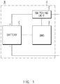
- FIG. 1 is a block diagram showing the configuration of a battery rack.
- a battery rack R that can be applied to a high voltage battery system includes a battery C capable of charging and discharging in which one or more battery modules (e.g., battery packs) are connected in series or in parallel, a switching unit 2 connected in series to the + terminal (anode) side or the - terminal (cathode) side of the battery C to control the charge/discharge current flow of the battery C, and a battery management system 3 (hereinafter also referred to as BMS) that monitors the voltage, current, temperature, etc. of the battery and controls and manages it to prevent overcharge and overdischarge.
- BMS battery management system 3
- the switching unit 2 is a switching element for controlling the current flow for the charging or discharging of the battery C, and may be a configuration that is essentially provided for the operation of the battery rack R.
- the BMS 3 can monitor voltage, current, temperature, and the like as the state of the battery C.
- the BMS 3 may include a circuit that receives a value obtained by measuring various parameters such as voltage, current, and temperature, and performs a process of the received value.
- the battery rack R is provided in the chassis 4 as a housing, and the chassis 4 is grounded.
- Each of the components of the battery rack R that is, the battery C, the switching unit 2, the BMS 3, and the chassis 4, is designed to be insulated therebetween, so that an insulation resistance exists between the battery and the chassis.
- FIG. 2 is a block diagram showing a configuration of an insulation resistance measurement apparatus according to an embodiment of the present invention.
- FIG. 3 is a diagram schematically illustrating a circuit configuration of an insulation resistance measurement apparatus according to an embodiment of the present invention.
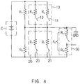
- FIG. 4 is an equivalent circuit of FIG. 3 .
- the insulation resistance measurement apparatus may include a first resistance unit 10, a second resistance unit 20, a voltage measurement unit 30, and an insulation resistance calculation unit 40.
- the first resistor unit 10 has a configuration in which one end is connected to the anode of the battery C and the other end is connected to the ground, and may optionally have a first resistance value or a second resistance value greater than the first resistance value under control.
- the first resistor unit 10 may have a circuit configuration in which the first resistance value unit that is ON/OFF controlled by the first switch 11 and the second resistance value unit that is ON/OFF controlled by the second switch 13 are connected in parallel between the anode of the battery C and the ground.
- the first switch 11 and the second switch 13 may be controlled by an insulation resistance calculation unit 40.
- the first resistance unit 10 may have a first resistance value or a second resistance value selectively by ON/OFF control of the first switch 11 and the second switch 13.
- the first resistance value unit may be a resistance unit having a first resistance value, and may include, for example, a plurality of resistors (five R1s) connected in series and a first switch 11.
- the second resistance value unit may be a resistance unit having a second resistance value, and may include, for example, a plurality of resistors (five R1s and two R2s) connected in series and a second switch 13.
- the first resistance value and the second resistance value are values set assuming that the actual insulation resistance value is high or low.
- first resistance value unit and the second resistance value unit share a plurality of resistors (five R1s), as long as the first resistance value unit and the second resistance value unit have the first resistance value and the second resistance value, respectively, they may not be shared and may be designed with different resistors.
- first resistance value unit and the second resistance value unit are shown to be formed of a plurality of resistors, the resistors may be designed as one or more resistors as long as they have a set resistance value.
- the third switch 21 and the fourth switch 23 of the second resistance unit 20 are controlled to be OFF.
- one end is connected to the cathode of the battery C and the other end is connected to the ground, and it may optionally have a third resistance value or a fourth resistance value greater than the third resistance value.
- the second resistor unit 20 may have a circuit configuration in which the third resistance value unit that is ON/OFF controlled by the third switch 21 and the fourth resistance value unit that is ON/OFF controlled by the fourth switch 23 are connected in parallel between the cathode of the battery C and the ground.
- the third switch 21 and the fourth switch 23 may be controlled by the insulation resistance calculation unit 40.
- the second resistance unit 20 may have a third resistance value or a fourth resistance value selectively by ON/OFF control of the third switch 21 and the fourth switch 23.
- the third resistance value unit may be a resistance unit having a third resistance value, and may include, for example, a plurality of resistors (five R1s) connected in series and a third switch 21.
- the fourth resistance value unit may be a resistance unit having a fourth resistance value, and may include, for example, a plurality of resistors (five R1s and two R2s) connected in series and a fourth switch 23.
- the third resistance value and the fourth resistance value are values set assuming that the actual insulation resistance value is high or low and may be the same as the first resistance value and the second resistance value, respectively.
- the third resistance value unit and the fourth resistance value unit share a plurality of resistors (five R1s), as long as the third resistance value unit and the fourth resistance value unit have the third resistance value and the fourth resistance value, respectively, they may not be shared and may be designed with different resistors.
- the third resistance value unit and the fourth resistance value unit are shown to be formed of a plurality of resistors, the resistors may be designed as one or more resistors as long as they have a set resistance value.
- the third switch 21 or the fourth switch 23 of the second resistance unit 20 is controlled to be ON
- the first switch 11 and the second switch 13 of the first resistance unit 10 are controlled to be OFF.
- the first resistance value to the fourth resistance value may be changed according to the battery C or a device in which the battery C is mounted.
- the battery C may be a battery rack, and the ground may be a chassis of the battery rack.
- the voltage measurement unit 30 is a configuration for measuring the voltage of each part of the circuit, and may measure voltages related to both ends of the first resistance unit 10 or the second resistance unit 20. In particular, in order to measure the insulation resistance of the battery, for example, the voltage can be measured from some resistance of the voltage distribution unit 50 described later.
- the insulation resistance calculation unit 40 is configured to calculate the insulation resistance of the battery using the first to fourth resistance values and the voltage measured by the voltage measurement unit 30, and for example, may calculate a first insulation resistance value between the anode of the battery C and the ground and a second insulation resistance value between the cathode of the battery C and the ground.
- the insulation resistance calculation unit 40 may be implemented as, for example, a microcontroller unit (MCU).
- the voltage distribution unit 50 is configured to distribute the voltage at a predetermined voltage distribution ratio during insulation resistance measurement, and for example, as in FIG. FIG. 3 , may be connected in parallel with the second resistance unit 20 and may be composed of a plurality of resistors (four R3s and one R4) connected in series. At this time, the voltage measurement unit 30 may measure the voltage from both ends of the resistor R4. Furthermore, the voltage distribution ratio is determined by the resistance ratio between the plurality of resistors connected in series, and is set for easy voltage measurement.
- the voltage distribution unit 50 is connected in parallel with the second resistance unit 20 in FIG. 3 , but may be designed to be connected in parallel with the first resistance unit 10.
- the voltage distribution unit 50 may further include a fifth switch 55 connected in series with a plurality of resistors (four R3s and one R4) to be ON/OFF controlled.
- a resistor R5 and a capacitor C1 for circuit protection, such as noise removal may be further provided between the voltage distribution unit 50 and the insulation resistance calculation unit 40, and in addition, a switch 65 may be further provided between the first resistance unit 10 and the second resistance unit 20 and the ground.
- the circuit configuration of the insulation resistance measurement apparatus in FIG. 3 may be represented by an equivalent circuit as shown in FIG. 4 . That is, in the first resistance unit 10, the first resistance value may be represented by Rg and the second resistance value may be represented by RG, and in the second resistance unit 20, the third resistance value may be represented by Rf and the fourth resistance value may be represented by RF.
- the plurality of resistors of the voltage distribution unit 50 may be represented by Re1 and Re2, and the sum of the plurality of resistors may be represented by RE.
- the insulation resistance calculation unit 40 may calculate the first insulation resistance value RP between the anode of the battery C and the ground and the second insulation resistance value RN between the cathode of the battery C and the ground using the voltage measured by the voltage measurement unit 30 from some resistors Re2 of the voltage distribution unit 50.
- the insulation resistance calculation unit 40 is provided with a plurality of insulation resistance measurement modes having a relatively low error rate in different measurement ranges, for example, a first insulation resistance measurement mode and a second insulation resistance measurement mode so that the insulation resistance calculation unit 40 calculates first and second insulation resistance values RP and RN using the first resistance value Rg and the third resistance value Rf in the first insulation resistance measurement mode, and calculates the first and second insulation resistance values RP and RN using the second resistance value RG and the fourth resistance value RF in the second insulation resistance measurement mode.
- a first insulation resistance measurement mode and a second insulation resistance measurement mode so that the insulation resistance calculation unit 40 calculates first and second insulation resistance values RP and RN using the first resistance value Rg and the third resistance value Rf in the first insulation resistance measurement mode, and calculates the first and second insulation resistance values RP and RN using the second resistance value RG and the fourth resistance value RF in the second insulation resistance measurement mode.
- the first insulation resistance measurement mode by using the voltage measured from some resistors Re2 of the voltage distribution unit 50 when the first switch 11 is controlled to be ON and the second to fourth switches 13, 21, and 23 are controlled to be OFF and the voltage measured from some resistors Re2 of the voltage distribution unit 50 when the third switch 21 is controlled to be ON and the first, second, and fourth switches 11, 13, and 23 are controlled to be OFF, the first and second insulation resistance values RP and RN may be calculated.
- the first and second insulation resistance values RP and RN may be calculated.
- the insulation resistance calculation unit 40 may calculate first and second insulation resistance values in the plurality of insulation resistance measurement modes, respectively.
- a plurality of insulation resistance measurement modes are modes that are changed by changing a resistance value of the first resistance unit 10 having one end connected to the anode of the battery and the other end connected to the ground and a resistance value of the second resistance unit 20 having one end connected to the cathode of the battery and the other end connected to the ground, and for example, the measurement range of the first insulation resistance measurement mode has a relatively low error rate when the actual insulation resistance is low and the measurement range of the second insulation resistance measurement mode has a relatively low error rate when the actual insulation resistance is high.
- the insulation resistance calculation unit 40 determines one insulation resistance value among the calculated insulation resistance values as the actual insulation resistance value.
- a measurement range is determined corresponding to the insulation resistance value calculated in the first insulation resistance measurement mode and the insulation resistance value calculated in the second insulation resistance measurement mode, and the insulation resistance value calculated in the measurement mode having a relatively low error rate in the measurement range determined among the first insulation resistance measurement mode and the second insulation resistance measurement mode is determined as the actual insulation resistance value.
- the insulation resistance measurement apparatus may be implemented as a portion of functions of the battery management system of the battery rack, or may be implemented as a separate device.
- the present invention when measuring the insulation resistance of the battery, by calculating the insulation resistance in the measurement range within the error range corresponding to the actual insulation resistance value, that is, the measurement range having a relatively low error rate, it is possible to prevent the measurement accuracy from being lowered. This allows more accurate insulation resistance values to be measured and reported when the battery system is diagnosed.
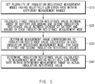
- FIG. 5 is a flowchart showing an insulation resistance measurement method according to an embodiment of the present invention.
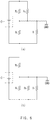
- FIGS. 6(a) and 6(b) are diagrams for explaining a method of calculating insulation resistance values in a second insulation resistance measurement mode according to an embodiment of the present invention.
- FIGS. 7(a) and 7(b) are diagrams for explaining a method of calculating insulation resistance values in a first insulation resistance measurement mode according to an embodiment of the present invention.
- the insulation resistance measurement method sets a plurality of insulation resistance measurement modes having a relatively low error rate in different measurement ranges (S10).
- the plurality of insulation resistance measurement modes are modes changed by changing a resistance value of the first resistance unit 10 having one end connected to the anode of the battery C and the other end connected to the ground and a resistance value of the second resistance unit 20 having one end connected to the cathode of the battery C and the other end connected to ground.
- the plurality of insulation resistance measurement modes may include a first insulation resistance measurement mode having a relatively low error rate as a measurement range when the actual insulation resistance has a low value and a second insulation resistance measurement mode having a relatively low error rate as a measurement range when the actual insulation resistance has a high value.
- a first insulation resistance value RP between the anode of the battery C and the ground and a second insulation resistance value RN between the cathode of the battery C and the ground are calculated by respective insulation resistance measurement modes (S20).
- Equation 1 for the measured voltage A can be derived from the equivalent circuit.
- R N / / R E R N / / R E + R P / / R G ⁇ C ⁇ D A
- RN is a second insulation resistance value
- RE is the sum of the resistance values of the voltage distribution unit
- RP is the first insulation resistance value
- C is the voltage value of the battery
- D is the voltage distribution ratio for measuring of the voltage distribution unit.
- the measured voltage A is, for example, the voltage measured from the resistor Re2 of the voltage distribution unit.
- Equation 2 for the measured voltage B can be derived from the equivalent circuit.
- R N / / R E / / R F R N / / R E / / R F + R P ⁇ C ⁇ D B
- Equation 1 when (RN//RE) is X, Equation 1 may be expressed as Equation 3 and Equation 2 may be expressed as Equation 4.
- Equation 3 when (RN//RE) is X, Equation 1 may be expressed as Equation 3 and Equation 2 may be expressed as Equation 4.
- X + R P / / R G X C ⁇ D A
- X / / R F + R P X / / R F C ⁇ D B
- Equation 3 A ⁇ R G ⁇ R P R P + R G ⁇ C ⁇ D ⁇ A
- Equation 4 if Equation 4 is summarized as X, it can be expressed as Equation 6.
- X A ⁇ R G ⁇ R P R P + R G ⁇ C ⁇ D ⁇ A
- X B ⁇ R F ⁇ R P C ⁇ D ⁇ R F ⁇ B ⁇ R F ⁇ B ⁇ R P
- Equation 8 the second insulation resistance value RN can be derived as in Equation 8.
- R N A ⁇ R E ⁇ R G ⁇ R P R E ⁇ R P + R G ⁇ C ⁇ D ⁇ A ⁇ A ⁇ R G ⁇ R P
- the first and second insulation resistance values can be calculated in the second insulation resistance measurement mode.
- the equation for the measured voltage from the equivalent circuit is derived, and as shown in FIG. 7(b) , when the second resistance unit 20 has the third resistance value Rf, that is, when the third switch 21 is controlled to be ON and the first, second, and fourth switches 11, 13, and 23 are controlled to be OFF, the equation for the measured voltage can be derived from the equivalent circuit to calculate the first and second insulation resistance values.
- the measurement range corresponding to the insulation resistance value calculated in each insulation resistance measurement mode is determined (S30).
- the insulation resistance value calculated in the measurement mode having a relatively low error rate in the determined measurement range is determined as the actual insulation resistance value (S40).
- the measurement error in each insulation resistance measurement mode can be obtained by repeated experiments, as shown in FIG. 8 .
- FIG. 8(a) is a table showing a measurement error (%) with respect to the insulation resistance value in the first insulation resistance measurement mode
- FIG. 8(b) is a table showing measurement error (%) with respect to the insulation resistance value in the second insulation resistance measurement mode.
- the measurement range of the first insulation resistance measurement mode may be set to a range having a relatively low error rate, for example, a range of 10,000 k ohms or less.
- the measurement range of the second insulation resistance measurement mode may be set to a range having a relatively low error rate, for example, a range of 10,000 k ohms or more.
- the insulation resistance value calculated in the first insulation resistance measurement mode may be determined as the actual insulation resistance value in operation S40 of FIG. 5 .
- the first insulation resistance measurement mode is used and in order to accurately measure a relatively high insulation resistance value, the second insulation resistance measurement mode is used.
- the first resistance unit 10 and the second resistance unit 20 of the insulation resistance measurement apparatus have a parallel circuit structure using a plurality of switches and a plurality of resistors in order to have a plurality of resistance values as shown in FIG. 3 but for example, as shown in FIG. 9 , they may be designed using a variable resistor.
- FIG. 9 is a diagram schematically illustrating a circuit configuration of an insulation resistance measurement apparatus according to another embodiment of the present invention.
- the first resistance unit 10a may include a first variable resistance unit R1a that is ON/OFF controlled by the first switch 11 and can be converted into a first resistance value or a second resistance value between the anode of battery C and the ground
- the second resistance unit 20a may include a second variable resistance unit R2a that is ON/OFF controlled by the third switch 21a and can be converted into a third resistance value or a fourth resistance value between the cathode of the battery C and the ground.
- Other configurations are as described above.
- the voltage distribution unit 50 of the insulation resistance measurement apparatus is connected in parallel with the second resistance unit 20, as shown in FIG. 2 , but for example, as shown in FIG. 10 , may be designed to be connected in parallel with the first resistance unit 10.
- FIG. 10 is a block diagram showing the configuration of an insulation resistance measurement apparatus according to another embodiment of the present invention.
- the voltage distribution unit 50a may be designed to have a parallel structure with the first resistance unit 10 between the anode of the battery C and the ground. Other configurations are as described above.
- the insulation resistance measurement method according to an embodiment of the present invention described above may be implemented as a program stored in a recording medium for performing each operation, and the corresponding program is stored in the memory of the BMS of the battery rack and can be executed by the MCU.
- the method of the present invention can be written in a computer program.
- the code and code segments constituting the program can be easily inferred by computer programmers in the art.
- the created program is stored in a computer-readable recording medium (information storage medium), and can be read and executed by a computer to realize the method of the present invention.
- the recording medium may include any type of computer-readable recording medium.
- the recording medium may be provided separately from the MCU, or may be configured integrally with the MCU.
- FIG. 11 is a block diagram illustrating a hardware configuration of a battery management system (BMS) according to an embodiment of the present invention.
- BMS battery management system
- the battery management system 300 may include an MCU 310 for controlling various processing and each configuration, a memory 320 for recording an operating system program and various programs (for example, an insulation resistance measurement program of a battery), an input/output interface 330 providing an input interface and an output interface between the battery and/or the switching unit, and a communication interface 340 capable of communicating with the outside through a wired or wireless communication network.
- the computer program according to the present invention may be recorded in the memory 320 and processed by the microcontroller 310 to be implemented as a module for performing the respective functional blocks shown in FIG. 2 .
Abstract
Description
- This application claims priority to and the benefit of
Korean Patent Application No. 10-2019-0000520, filed on January 3, 2019 - The present invention relates to an apparatus and a method for measuring an insulation resistance of a battery.
- In high voltage battery systems, a certain level of insulation must be maintained at all times to protect users from the risk of short circuits. Accordingly, more accurate insulation resistance measurement is required when a battery system is diagnosed.
- In the conventional insulation resistance measurement, the distribution resistor is alternately connected to either of the battery cathode and anode with reference to the ground (e.g., chassis), and the insulation resistance value was calculated from the measured distribution voltage value.
- However, conventionally, since the measurement range within the allowable error range is limited based on- a designed distribution resistance value, for example, as in the case where the actual insulation resistance value is greater than the sum of pre-designed distribution resistance values at the measurement terminals of the battery's cathode or anode, the calculated insulation resistance value is out of the measurement range within the error range, so that there was a problem of low measurement accuracy.
- The present invention has been made to solve the above problems, and an object of the present invention is to provide an insulation resistance measuring apparatus and method which can prevent the measurement accuracy from being lowered by calculating the insulation resistance in a measurement range within an error range corresponding to an actual insulation resistance value when measuring an insulation resistance of a battery.
- An insulation resistance measurement apparatus according to an embodiment of the present invention includes: a first resistance unit having one end connected to an anode of a battery and the other end connected to a ground, and optionally having a first resistance value or a second resistance value greater than the first resistance value according to control; a second resistance unit having one end connected to a cathode of the battery and the other end connected to the ground, and optionally having a third resistance value or a fourth resistance value greater than the third resistance value according to control; a voltage measurement unit configured to measure a voltage related to both ends of the first resistance unit or the second resistance unit; and an insulation resistance calculation unit configured to calculate a first insulation resistance value between the anode of the battery and the ground and a second insulation resistance value between the cathode of the battery and the ground by using the first to fourth resistance values and a voltage measured by the voltage measurement unit.
- In addition, the insulation resistance measurement apparatus according to an embodiment of the present invention further includes a voltage distribution unit connected in parallel with the first resistance unit or the second resistance unit and formed of a plurality of resistors connected in series. In this case, the insulation resistance calculation unit may calculate a first insulation resistance value between the anode of the battery and the ground and a second insulation resistance value between the cathode of the battery and the ground by using a voltage measured by some resistors of the voltage distribution unit as a voltage measured by the voltage measurement unit.
- The insulation resistance calculation unit has a first insulation resistance measurement mode and a second insulation resistance measurement mode having a relatively low error rate in different measurement ranges, calculates the first and second insulation resistance values using a first resistance value and a third resistance value in the first insulation resistance measurement mode, and calculates the first and second insulation resistance values using a second resistance value and a fourth resistance value in the second insulation resistance measurement mode.
- For example, in the case of the first insulation resistance measurement mode, by using a voltage measured from some resistors of the voltage distribution unit when the first switch is controlled to be ON and the second to fourth switches are controlled to be OFF and a voltage measured from some resistors of the voltage distribution unit when the third switch is controlled to be ON and the first, second and fourth switches are controlled to be OFF, the first and second insulation resistance values may be calculated.
- In addition, in the case of the second insulation resistance measurement mode, by using a voltage measured from some resistors of the voltage distribution unit when the second switch is controlled to be ON and the first, third, and fourth switches are controlled to be OFF and a voltage measured from some resistors of the voltage distribution unit when the fourth switch is controlled to be ON and the first to third switches are controlled to be OFF, the first and second insulation resistance values may be calculated.
- Furthermore, for each of the first and second insulation resistance values, the insulation resistance calculation unit determines the measurement range corresponding to the insulation resistance value calculated in the first insulation resistance measurement mode and the insulation resistance value calculated in the second insulation resistance measurement mode, and determines an insulation resistance value calculated in a measurement mode having a relatively low error rate in the determined measurement range among the first insulation resistance measurement mode and the second insulation resistance measurement mode as an actual insulation resistance value.
- The first resistance unit is formed as a first resistance value unit that is ON/OFF controlled by a first switch and a second resistance value unit that is ON/OFF controlled by a second switch are connected in parallel between the anode of the battery and the ground. For example, when the first switch or the second switch of the first resistance unit is controlled to be ON, the third switch and the fourth switch of the second resistance unit are controlled to be OFF.
- In addition, the second resistance unit is formed as a third resistance value unit that is ON/OFF controlled by a third switch and a fourth resistance value unit that is ON/OFF controlled by a fourth switch are connected in parallel between the cathode of the battery and the ground. For example, when the third switch or the fourth switch of the second resistance unit is controlled to be ON, the first switch and the second switch of the first resistance unit are controlled to be OFF.
- As another example, the first resistance unit is composed of a first variable resistance unit which is ON/OFF controlled by a first switch and convertible into the first resistance value or the second resistance value between the anode of the battery and the ground, and in the same manner, the second resistance unit is composed of a second variable resistance unit which is ON/OFF controlled by a third switch and convertible into the third resistance value or the fourth resistance value between the cathode of the battery and the ground.
- For example, the first to fourth resistance values are values that are changed according to a battery or a device in which a battery is mounted.
- The voltage distribution unit further includes a fifth switch connected in series with the plurality of resistors to be ON/OFF controlled.
- As one embodiment, the battery is a battery rack, and the ground is a chassis of the battery rack.
- Meanwhile, an insulation resistance measurement method according to an embodiment of the present invention includes: setting a plurality of insulation resistance measurement modes having a relatively low error rate in different measurement ranges to measure an insulation resistance of a battery; calculating a first insulation resistance value between an anode of the battery and a ground and a second insulation resistance value between a cathode of the battery and the ground by each insulation resistance measurement mode; determining, for each of the first and second insulation resistance values, the measurement range corresponding to an insulation resistance value calculated in each insulation resistance measurement mode; and determining an insulation resistance value calculated in a measurement mode having a relatively low error rate in the determined measurement range as an actual insulation resistance value.
- Here, when measuring an insulation resistance, the plurality of insulation resistance measurement modes are changed by changing a resistance value of a first resistance unit having, one end connected to the anode of the battery and the other end connected to the ground, and a resistance value of a second resistance unit having one end connected to the cathode of the battery and the other end connected to the ground.
- According to the present invention, when measuring the insulation resistance of the battery, it is possible to prevent the measurement accuracy from being lowered by calculating the insulation resistance in a measurement range within an error range corresponding to the actual insulation resistance value. This allows more accurate insulation resistance values to be measured and reported when the battery system is diagnosed.
- Other effects of the present invention will be further described according to the following examples.
-
-
FIG. 1 is a block diagram showing the configuration of a battery rack. -
FIG. 2 is a block diagram showing the configuration of an insulation resistance measurement apparatus according to an embodiment of the present invention. -
FIG. 3 is a diagram schematically illustrating a circuit configuration of an insulation resistance measurement apparatus according to an embodiment of the present invention. -
FIG. 4 is an equivalent circuit ofFIG. 3 . -
FIG. 5 is a flowchart showing an insulation resistance measurement method according to an embodiment of the present invention. -
FIGS. 6(a) and 6(b) are diagrams for explaining a method of calculating insulation resistance values in a second insulation resistance measurement mode according to an embodiment of the present invention. -
FIGS. 7(a) and 7(b) are diagrams for explaining a method of calculating insulation resistance values in a first insulation resistance measurement mode according to an embodiment of the present invention. -
FIG. 8(a) is a table showing a measurement error with respect to the insulation resistance value in the first insulation resistance measurement mode andFIG. 8(b) is a table showing measurement error with respect to the insulation resistance value in the second insulation resistance measurement mode. -
FIG. 9 is a diagram schematically illustrating a circuit configuration of an insulation resistance measurement apparatus according to another embodiment of the present invention. -
FIG. 10 is a block diagram showing the configuration of an insulation resistance measurement apparatus according to another embodiment of the present invention. -
FIG. 11 is a block diagram illustrating a hardware configuration of a battery management system according to an embodiment of the present invention. - Hereinafter, some embodiments of the present invention will be described in detail through exemplary drawings. It should be noted that, in assigning reference numerals to components of each drawing, although the components are displayed on different drawings, like reference numerals refer to like components. Additionally, in describing the inventive concept, detailed descriptions of well-known configurations or functions will be omitted if it is determined that they would obscure the subject matter of the inventive concept.
- First, the configuration of the battery rack will be briefly described with reference to
FIG. 1. FIG. 1 is a block diagram showing the configuration of a battery rack. - As shown in
FIG. 1 , for example, a battery rack R that can be applied to a high voltage battery system includes a battery C capable of charging and discharging in which one or more battery modules (e.g., battery packs) are connected in series or in parallel, aswitching unit 2 connected in series to the + terminal (anode) side or the - terminal (cathode) side of the battery C to control the charge/discharge current flow of the battery C, and a battery management system 3 (hereinafter also referred to as BMS) that monitors the voltage, current, temperature, etc. of the battery and controls and manages it to prevent overcharge and overdischarge. - Here, the
switching unit 2 is a switching element for controlling the current flow for the charging or discharging of the battery C, and may be a configuration that is essentially provided for the operation of the battery rack R. - In addition, the BMS 3 can monitor voltage, current, temperature, and the like as the state of the battery C. The BMS 3 may include a circuit that receives a value obtained by measuring various parameters such as voltage, current, and temperature, and performs a process of the received value.
- In addition, such a configuration of the battery rack R is provided in the
chassis 4 as a housing, and thechassis 4 is grounded. Each of the components of the battery rack R, that is, the battery C, theswitching unit 2, the BMS 3, and thechassis 4, is designed to be insulated therebetween, so that an insulation resistance exists between the battery and the chassis. - Since the configuration of the battery rack R and the BMS 3 is a known configuration, more detailed description thereof will be omitted.
- Next, an insulation resistance measurement apparatus according to an embodiment of the present invention will be described with reference to
FIGS. 2 to 4 .FIG. 2 is a block diagram showing a configuration of an insulation resistance measurement apparatus according to an embodiment of the present invention.FIG. 3 is a diagram schematically illustrating a circuit configuration of an insulation resistance measurement apparatus according to an embodiment of the present invention.FIG. 4 is an equivalent circuit ofFIG. 3 . - As shown in
FIG. 2 , the insulation resistance measurement apparatus according to an embodiment of the present invention may include afirst resistance unit 10, asecond resistance unit 20, avoltage measurement unit 30, and an insulationresistance calculation unit 40. - The
first resistor unit 10 has a configuration in which one end is connected to the anode of the battery C and the other end is connected to the ground, and may optionally have a first resistance value or a second resistance value greater than the first resistance value under control. - For example, as shown in
FIG. 3 , thefirst resistor unit 10 may have a circuit configuration in which the first resistance value unit that is ON/OFF controlled by thefirst switch 11 and the second resistance value unit that is ON/OFF controlled by thesecond switch 13 are connected in parallel between the anode of the battery C and the ground. For example, thefirst switch 11 and thesecond switch 13 may be controlled by an insulationresistance calculation unit 40. As such, thefirst resistance unit 10 may have a first resistance value or a second resistance value selectively by ON/OFF control of thefirst switch 11 and thesecond switch 13. - Here, the first resistance value unit may be a resistance unit having a first resistance value, and may include, for example, a plurality of resistors (five R1s) connected in series and a
first switch 11. In the same manner, the second resistance value unit may be a resistance unit having a second resistance value, and may include, for example, a plurality of resistors (five R1s and two R2s) connected in series and asecond switch 13. The first resistance value and the second resistance value are values set assuming that the actual insulation resistance value is high or low. AlthoughFIG. 3 illustrates that the first resistance value unit and the second resistance value unit share a plurality of resistors (five R1s), as long as the first resistance value unit and the second resistance value unit have the first resistance value and the second resistance value, respectively, they may not be shared and may be designed with different resistors. In addition, although the first resistance value unit and the second resistance value unit are shown to be formed of a plurality of resistors, the resistors may be designed as one or more resistors as long as they have a set resistance value. - For example, when the
first switch 11 or thesecond switch 13 of thefirst resistance unit 10 is controlled to be ON, thethird switch 21 and thefourth switch 23 of thesecond resistance unit 20 are controlled to be OFF. - In addition, in the
second resistance unit 20, one end is connected to the cathode of the battery C and the other end is connected to the ground, and it may optionally have a third resistance value or a fourth resistance value greater than the third resistance value. - For example, as shown in
FIG. 3 , thesecond resistor unit 20 may have a circuit configuration in which the third resistance value unit that is ON/OFF controlled by thethird switch 21 and the fourth resistance value unit that is ON/OFF controlled by thefourth switch 23 are connected in parallel between the cathode of the battery C and the ground. For example, thethird switch 21 and thefourth switch 23 may be controlled by the insulationresistance calculation unit 40. As such, thesecond resistance unit 20 may have a third resistance value or a fourth resistance value selectively by ON/OFF control of thethird switch 21 and thefourth switch 23. - Here, the third resistance value unit may be a resistance unit having a third resistance value, and may include, for example, a plurality of resistors (five R1s) connected in series and a
third switch 21. In the same manner, the fourth resistance value unit may be a resistance unit having a fourth resistance value, and may include, for example, a plurality of resistors (five R1s and two R2s) connected in series and afourth switch 23. The third resistance value and the fourth resistance value are values set assuming that the actual insulation resistance value is high or low and may be the same as the first resistance value and the second resistance value, respectively. AlthoughFIG. 3 illustrates that the third resistance value unit and the fourth resistance value unit share a plurality of resistors (five R1s), as long as the third resistance value unit and the fourth resistance value unit have the third resistance value and the fourth resistance value, respectively, they may not be shared and may be designed with different resistors. In addition, although the third resistance value unit and the fourth resistance value unit are shown to be formed of a plurality of resistors, the resistors may be designed as one or more resistors as long as they have a set resistance value. - For example, when the
third switch 21 or thefourth switch 23 of thesecond resistance unit 20 is controlled to be ON, thefirst switch 11 and thesecond switch 13 of thefirst resistance unit 10 are controlled to be OFF. - Here, the first resistance value to the fourth resistance value may be changed according to the battery C or a device in which the battery C is mounted.
- As an embodiment, the battery C may be a battery rack, and the ground may be a chassis of the battery rack.
- The
voltage measurement unit 30 is a configuration for measuring the voltage of each part of the circuit, and may measure voltages related to both ends of thefirst resistance unit 10 or thesecond resistance unit 20. In particular, in order to measure the insulation resistance of the battery, for example, the voltage can be measured from some resistance of thevoltage distribution unit 50 described later. - In addition, the insulation
resistance calculation unit 40 is configured to calculate the insulation resistance of the battery using the first to fourth resistance values and the voltage measured by thevoltage measurement unit 30, and for example, may calculate a first insulation resistance value between the anode of the battery C and the ground and a second insulation resistance value between the cathode of the battery C and the ground. In one example, the insulationresistance calculation unit 40 may be implemented as, for example, a microcontroller unit (MCU). - The
voltage distribution unit 50 is configured to distribute the voltage at a predetermined voltage distribution ratio during insulation resistance measurement, and for example, as in FIG.FIG. 3 , may be connected in parallel with thesecond resistance unit 20 and may be composed of a plurality of resistors (four R3s and one R4) connected in series. At this time, thevoltage measurement unit 30 may measure the voltage from both ends of the resistor R4. Furthermore, the voltage distribution ratio is determined by the resistance ratio between the plurality of resistors connected in series, and is set for easy voltage measurement. - In addition, the
voltage distribution unit 50 is connected in parallel with thesecond resistance unit 20 inFIG. 3 , but may be designed to be connected in parallel with thefirst resistance unit 10. In addition, as shown inFIG. 3 , in order to be separated from the circuit, thevoltage distribution unit 50 may further include afifth switch 55 connected in series with a plurality of resistors (four R3s and one R4) to be ON/OFF controlled. Also, as inFIG. 3 , a resistor R5 and a capacitor C1 for circuit protection, such as noise removal, may be further provided between thevoltage distribution unit 50 and the insulationresistance calculation unit 40, and in addition, aswitch 65 may be further provided between thefirst resistance unit 10 and thesecond resistance unit 20 and the ground. - For example, the circuit configuration of the insulation resistance measurement apparatus in
FIG. 3 may be represented by an equivalent circuit as shown inFIG. 4 . That is, in thefirst resistance unit 10, the first resistance value may be represented by Rg and the second resistance value may be represented by RG, and in thesecond resistance unit 20, the third resistance value may be represented by Rf and the fourth resistance value may be represented by RF. In addition, the plurality of resistors of thevoltage distribution unit 50 may be represented by Re1 and Re2, and the sum of the plurality of resistors may be represented by RE. - Accordingly, the insulation
resistance calculation unit 40 may calculate the first insulation resistance value RP between the anode of the battery C and the ground and the second insulation resistance value RN between the cathode of the battery C and the ground using the voltage measured by thevoltage measurement unit 30 from some resistors Re2 of thevoltage distribution unit 50. - For example, the insulation
resistance calculation unit 40 is provided with a plurality of insulation resistance measurement modes having a relatively low error rate in different measurement ranges, for example, a first insulation resistance measurement mode and a second insulation resistance measurement mode so that the insulationresistance calculation unit 40 calculates first and second insulation resistance values RP and RN using the first resistance value Rg and the third resistance value Rf in the first insulation resistance measurement mode, and calculates the first and second insulation resistance values RP and RN using the second resistance value RG and the fourth resistance value RF in the second insulation resistance measurement mode. - Specifically, in the case of the first insulation resistance measurement mode, by using the voltage measured from some resistors Re2 of the
voltage distribution unit 50 when thefirst switch 11 is controlled to be ON and the second tofourth switches voltage distribution unit 50 when thethird switch 21 is controlled to be ON and the first, second, andfourth switches - In a similar way, in the case of the second insulation resistance measurement mode, by using the voltage measured from some resistors Re2 of the
voltage distribution unit 50 when thesecond switch 13 is controlled to be ON and the first, third, andfourth switches voltage distribution unit 50 when thefourth switch 23 is controlled to be ON and the first tothird switches - As such, the insulation
resistance calculation unit 40 may calculate first and second insulation resistance values in the plurality of insulation resistance measurement modes, respectively. - Here, when measuring insulation resistance, a plurality of insulation resistance measurement modes are modes that are changed by changing a resistance value of the
first resistance unit 10 having one end connected to the anode of the battery and the other end connected to the ground and a resistance value of thesecond resistance unit 20 having one end connected to the cathode of the battery and the other end connected to the ground, and for example, the measurement range of the first insulation resistance measurement mode has a relatively low error rate when the actual insulation resistance is low and the measurement range of the second insulation resistance measurement mode has a relatively low error rate when the actual insulation resistance is high. - In addition, the insulation
resistance calculation unit 40 determines one insulation resistance value among the calculated insulation resistance values as the actual insulation resistance value. - For example, for each of the first and second insulation resistance values, a measurement range is determined corresponding to the insulation resistance value calculated in the first insulation resistance measurement mode and the insulation resistance value calculated in the second insulation resistance measurement mode, and the insulation resistance value calculated in the measurement mode having a relatively low error rate in the measurement range determined among the first insulation resistance measurement mode and the second insulation resistance measurement mode is determined as the actual insulation resistance value.
- In one example, the insulation resistance measurement apparatus according to an embodiment of the present invention may be implemented as a portion of functions of the battery management system of the battery rack, or may be implemented as a separate device.
- According to the present invention as described above, when measuring the insulation resistance of the battery, by calculating the insulation resistance in the measurement range within the error range corresponding to the actual insulation resistance value, that is, the measurement range having a relatively low error rate, it is possible to prevent the measurement accuracy from being lowered. This allows more accurate insulation resistance values to be measured and reported when the battery system is diagnosed.
- Next, the insulation resistance measurement method according to an embodiment of the present invention will be described with reference to
FIGS. 5 to 7 .FIG. 5 is a flowchart showing an insulation resistance measurement method according to an embodiment of the present invention.FIGS. 6(a) and 6(b) are diagrams for explaining a method of calculating insulation resistance values in a second insulation resistance measurement mode according to an embodiment of the present invention.FIGS. 7(a) and 7(b) are diagrams for explaining a method of calculating insulation resistance values in a first insulation resistance measurement mode according to an embodiment of the present invention. - As shown in
FIG. 5 , first, in order to measure the insulation resistance of the battery C, the insulation resistance measurement method according to an embodiment of the present invention sets a plurality of insulation resistance measurement modes having a relatively low error rate in different measurement ranges (S10). - As described above, when measuring insulation resistance, the plurality of insulation resistance measurement modes are modes changed by changing a resistance value of the
first resistance unit 10 having one end connected to the anode of the battery C and the other end connected to the ground and a resistance value of thesecond resistance unit 20 having one end connected to the cathode of the battery C and the other end connected to ground. - For example, the plurality of insulation resistance measurement modes may include a first insulation resistance measurement mode having a relatively low error rate as a measurement range when the actual insulation resistance has a low value and a second insulation resistance measurement mode having a relatively low error rate as a measurement range when the actual insulation resistance has a high value.
- Next, a first insulation resistance value RP between the anode of the battery C and the ground and a second insulation resistance value RN between the cathode of the battery C and the ground are calculated by respective insulation resistance measurement modes (S20).
- For example, as the second insulation resistance measurement mode, as shown in
FIG. 6(a) , when thefirst resistance unit 10 has a second resistance value RG, that is, when thesecond switch 13 is controlled to be ON and the first, third, andfourth switches 
- Here, RN is a second insulation resistance value, RE is the sum of the resistance values of the voltage distribution unit, RP is the first insulation resistance value, C is the voltage value of the battery, and D is the voltage distribution ratio for measuring of the voltage distribution unit. Here, the measured voltage A is, for example, the voltage measured from the resistor Re2 of the voltage distribution unit.
- In addition, as the second insulation resistance measurement mode, as shown in
FIG. 6(b) , when thesecond resistance unit 20 has a fourth resistance value RF, that is, when thefourth switch 23 is controlled to be ON and the first tothird switches Equation 2 for the measured voltage B can be derived from the equivalent circuit.
- In this case, when (RN//RE) is X, Equation 1 may be expressed as Equation 3 and
Equation 2 may be expressed asEquation 4.

- Here, if Equation 3 is summarized as X, it can be expressed as Equation 5, and if
Equation 4 is summarized as X, it can be expressed as Equation 6.

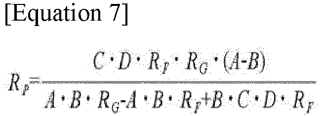
- Accordingly, by using equations 5 and 6 as simultaneous equations, X can be eliminated to derive the first insulation resistance value RP as shown in Equation 7.
- Subsequently, by substituting X=(RN//RE) into Equation 5, the second insulation resistance value RN can be derived as in Equation 8.

- In this manner, the first and second insulation resistance values can be calculated in the second insulation resistance measurement mode.
- In the same manner, as the first insulation resistance measurement mode, as shown in
FIG. 7(a) , when thefirst resistance unit 10 has the first resistance value Rg, that is, when thefirst switch 11 is controlled to be ON and the second tofourth switches FIG. 7(b) , when thesecond resistance unit 20 has the third resistance value Rf, that is, when thethird switch 21 is controlled to be ON and the first, second, andfourth switches - Back to
FIG. 5 , for each of the calculated first and second insulation resistance values, the measurement range corresponding to the insulation resistance value calculated in each insulation resistance measurement mode is determined (S30). - Subsequently, the insulation resistance value calculated in the measurement mode having a relatively low error rate in the determined measurement range is determined as the actual insulation resistance value (S40).
- The measurement error in each insulation resistance measurement mode can be obtained by repeated experiments, as shown in
FIG. 8 . - For example,
FIG. 8(a) is a table showing a measurement error (%) with respect to the insulation resistance value in the first insulation resistance measurement mode andFIG. 8(b) is a table showing measurement error (%) with respect to the insulation resistance value in the second insulation resistance measurement mode. - As shown in
FIG. 8(a) , it can be seen that in the first insulation resistance measurement mode, an error of a relatively small insulation resistance value is lower than an error of a relatively large insulation resistance value. Accordingly, the measurement range of the first insulation resistance measurement mode may be set to a range having a relatively low error rate, for example, a range of 10,000 k ohms or less. - In addition, as shown in
FIG. 8(b) , it can be seen that in the second insulation resistance measurement mode, an error of a relatively large insulation resistance value is lower than an error of a relatively small insulation resistance value. Accordingly, the measurement range of the second insulation resistance measurement mode may be set to a range having a relatively low error rate, for example, a range of 10,000 k ohms or more. - For example, when the first or second insulation resistance values calculated in the first and second insulation resistance measurement modes are all 10,000 k ohms or less, it may be determined that the corresponding measurement range corresponds to the measurement range of the relatively low first insulation resistance measurement mode in operation S30 of
FIG. 5 , and the insulation resistance value calculated in the first insulation resistance measurement mode may be determined as the actual insulation resistance value in operation S40 ofFIG. 5 . - Accordingly, in order to accurately measure a relatively low insulation resistance value, the first insulation resistance measurement mode is used and in order to accurately measure a relatively high insulation resistance value, the second insulation resistance measurement mode is used.
- When measuring the insulation resistance of the battery C in such a manner, by calculating the insulation resistance within the measurement range corresponding to the actual insulation resistance value, it is possible to prevent the measurement accuracy from being lowered.
- On the other hand, it is described in the above description that the
first resistance unit 10 and thesecond resistance unit 20 of the insulation resistance measurement apparatus have a parallel circuit structure using a plurality of switches and a plurality of resistors in order to have a plurality of resistance values as shown inFIG. 3 but for example, as shown inFIG. 9 , they may be designed using a variable resistor. -
FIG. 9 is a diagram schematically illustrating a circuit configuration of an insulation resistance measurement apparatus according to another embodiment of the present invention. - As shown in
FIG. 9 , in an insulation resistance measurement apparatus according to another embodiment of the present invention, thefirst resistance unit 10a may include a first variable resistance unit R1a that is ON/OFF controlled by thefirst switch 11 and can be converted into a first resistance value or a second resistance value between the anode of battery C and the ground, and in the same manner, thesecond resistance unit 20a may include a second variable resistance unit R2a that is ON/OFF controlled by thethird switch 21a and can be converted into a third resistance value or a fourth resistance value between the cathode of the battery C and the ground. Other configurations are as described above. - In the above description, the
voltage distribution unit 50 of the insulation resistance measurement apparatus is connected in parallel with thesecond resistance unit 20, as shown inFIG. 2 , but for example, as shown inFIG. 10 , may be designed to be connected in parallel with thefirst resistance unit 10. -
FIG. 10 is a block diagram showing the configuration of an insulation resistance measurement apparatus according to another embodiment of the present invention. - As shown in
FIG. 10 , thevoltage distribution unit 50a may be designed to have a parallel structure with thefirst resistance unit 10 between the anode of the battery C and the ground. Other configurations are as described above. - As another embodiment, the insulation resistance measurement method according to an embodiment of the present invention described above may be implemented as a program stored in a recording medium for performing each operation, and the corresponding program is stored in the memory of the BMS of the battery rack and can be executed by the MCU. In other words, the method of the present invention can be written in a computer program. And, the code and code segments constituting the program can be easily inferred by computer programmers in the art. Further, the created program is stored in a computer-readable recording medium (information storage medium), and can be read and executed by a computer to realize the method of the present invention. Then, the recording medium may include any type of computer-readable recording medium. The recording medium may be provided separately from the MCU, or may be configured integrally with the MCU.
- For example, the BMS of the battery rack of the present invention may be implemented as shown in
FIG. 11. FIG. 11 is a block diagram illustrating a hardware configuration of a battery management system (BMS) according to an embodiment of the present invention. - As shown in
FIG. 11 , thebattery management system 300 may include anMCU 310 for controlling various processing and each configuration, amemory 320 for recording an operating system program and various programs (for example, an insulation resistance measurement program of a battery), an input/output interface 330 providing an input interface and an output interface between the battery and/or the switching unit, and acommunication interface 340 capable of communicating with the outside through a wired or wireless communication network. As described above, the computer program according to the present invention may be recorded in thememory 320 and processed by themicrocontroller 310 to be implemented as a module for performing the respective functional blocks shown inFIG. 2 . - Although the present invention has been described above by limited embodiments and drawings, the present invention is not limited thereto, and it will be apparent to those skilled in the art that the present invention may be implemented in various ways within the equivalent scope of the technical spirit of the present invention and the claims to be described below.
Claims (15)
- An insulation resistance measurement apparatus comprising:a first resistance unit having one end connected to an anode of a battery and the other end connected to a ground, and optionally having a first resistance value or a second resistance value greater than the first resistance value according to control;a second resistance unit having one end connected to a cathode of the battery and the other end connected to the ground, and optionally having a third resistance value or a fourth resistance value greater than the third resistance value according to control;a voltage measurement unit configured to measure a voltage related to both ends of the first resistance unit or the second resistance unit; andan insulation resistance calculation unit configured to calculate a first insulation resistance value between the anode of the battery and the ground and a second insulation resistance value between the cathode of the battery and the ground by using the first to fourth resistance values and a voltage measured by the voltage measurement unit.
- The insulation resistance measurement apparatus of claim 1, further comprising a voltage distribution unit connected in parallel with the first resistance unit or the second resistance unit and formed of a plurality of resistors connected in series,
wherein the insulation resistance calculation unit calculates a first insulation resistance value between the anode of the battery and the ground and a second insulation resistance value between the cathode of the battery and the ground by using a voltage measured by some resistors of the voltage distribution unit as a voltage measured by the voltage measurement unit. - The insulation resistance measurement apparatus of claim 2, wherein the insulation resistance calculation unit has a first insulation resistance measurement mode and a second insulation resistance measurement mode having a relatively low error rate in different measurement ranges, and is configured to:calculates the first and second insulation resistance values using a first resistance value and a third resistance value in the first insulation resistance measurement mode, andcalculates the first and second insulation resistance values using a second resistance value and a fourth resistance value in the second insulation resistance measurement mode.
- The insulation resistance measurement apparatus of claim 3, wherein for each of the first and second insulation resistance values, the insulation resistance calculation unit determines the measurement range corresponding to the insulation resistance value calculated in the first insulation resistance measurement mode and the insulation resistance value calculated in the second insulation resistance measurement mode, and determines an insulation resistance value calculated in a measurement mode having a relatively low error rate in the determined measurement range among the first insulation resistance measurement mode and the second insulation resistance measurement mode as an actual insulation resistance value.
- The insulation resistance measurement apparatus of claim 3, wherein the first resistance unit is formed as a first resistance value unit that is ON/OFF controlled by a first switch and a second resistance value unit that is ON/OFF controlled by a second switch are connected in parallel between the anode of the battery and the ground,
wherein the second resistance unit is formed as a third resistance value unit that is ON/OFF controlled by a third switch and a fourth resistance value unit that is ON/OFF controlled by a fourth switch are connected in parallel between the cathode of the battery and the ground. - The insulation resistance measurement apparatus of claim 5, wherein when the first switch or the second switch of the first resistance unit is controlled to be ON, the third switch and the fourth switch of the second resistance unit are controlled to be OFF.
- The insulation resistance measurement apparatus of claim 5, wherein when the third switch or the fourth switch of the second resistance unit is controlled to be ON, the first switch and the second switch of the first resistance unit are controlled to be OFF.
- The insulation resistance measurement apparatus of claim 5, wherein in the case of the first insulation resistance measurement mode, by using a voltage measured from some resistors of the voltage distribution unit when the first switch is controlled to be ON and the second to fourth switches are controlled to be OFF and a voltage measured from some resistors of the voltage distribution unit when the third switch is controlled to be ON and the first, second and fourth switches are controlled to be OFF, the first and second insulation resistance values are calculated.
- The insulation resistance measurement apparatus of claim 5, wherein in the case of the second insulation resistance measurement mode, by using a voltage measured from some resistors of the voltage distribution unit when the second switch is controlled to be ON and the first, third, and fourth switches are controlled to be OFF and a voltage measured from some resistors of the voltage distribution unit when the fourth switch is controlled to be ON and the first to third switches are controlled to be OFF, the first and second insulation resistance values are calculated.
- The insulation resistance measurement apparatus of claim 1, wherein the first to fourth resistance values are values that are changed according to a battery or a device in which a battery is mounted.
- The insulation resistance measurement apparatus of claim 1, wherein the voltage distribution unit further comprises a fifth switch connected in series with the plurality of resistors to be ON/OFF controlled.
- The insulation resistance measurement apparatus of claim 1, wherein the battery is a battery rack, and the ground is a chassis of the battery rack.
- The insulation resistance measurement apparatus of claim 3, wherein the first resistance unit is composed of a first variable resistance unit which is ON/OFF controlled by a first switch and changeable between the first resistance value and the second resistance value, between the anode of the battery and the ground,
wherein the second resistance unit is composed of a second variable resistance unit which is ON/OFF controlled by a third switch and changeable between the third resistance value or the fourth resistance value between the cathode of the battery and the ground. - An insulation resistance measurement method comprising:setting a plurality of insulation resistance measurement modes having a relatively low error rate in different measurement ranges to measure an insulation resistance of a battery;calculating a first insulation resistance value between an anode of the battery and a ground and a second insulation resistance value between a cathode of the battery and the ground by each insulation resistance measurement mode;determining, for each of the first and second insulation resistance values, the measurement range corresponding to an insulation resistance value calculated in each insulation resistance measurement mode; anddetermining an insulation resistance value calculated in a measurement mode having a relatively low error rate in the determined measurement range as an actual insulation resistance value.
- The insulation resistance measurement method of claim 14, wherein when measuring an insulation resistance, the plurality of insulation resistance measurement modes are changed by changing a resistance value of a first resistance unit having, one end connected to the anode of the battery and the other end connected to the ground, and a resistance value of a second resistance unit having one end connected to the cathode of the battery and the other end connected to the ground.
Applications Claiming Priority (2)
| Application Number | Priority Date | Filing Date | Title |
|---|---|---|---|
| KR1020190000520A KR20200084517A (en) | 2019-01-03 | 2019-01-03 | Insulation resistance measurement apparatus and method thereof |
| PCT/KR2019/018052 WO2020141768A1 (en) | 2019-01-03 | 2019-12-18 | Insulation resistance measuring device and method |
Publications (2)
| Publication Number | Publication Date |
|---|---|
| EP3869209A1 true EP3869209A1 (en) | 2021-08-25 |
| EP3869209A4 EP3869209A4 (en) | 2022-01-26 |
Family
ID=71406901
Family Applications (1)
| Application Number | Title | Priority Date | Filing Date |
|---|---|---|---|
| EP19907369.3A Pending EP3869209A4 (en) | 2019-01-03 | 2019-12-18 | Insulation resistance measuring device and method |
Country Status (6)
| Country | Link |
|---|---|
| US (1) | US11906591B2 (en) |
| EP (1) | EP3869209A4 (en) |
| JP (1) | JP7173642B2 (en) |
| KR (1) | KR20200084517A (en) |
| CN (1) | CN113692539A (en) |
| WO (1) | WO2020141768A1 (en) |
Families Citing this family (10)
| Publication number | Priority date | Publication date | Assignee | Title |
|---|---|---|---|---|
| KR20200109925A (en) * | 2019-03-15 | 2020-09-23 | 에스케이이노베이션 주식회사 | Apparatus for measuring insulation resistance |
| JP7248221B2 (en) * | 2019-10-31 | 2023-03-29 | エルジー エナジー ソリューション リミテッド | Earth leakage detection device, earth leakage detection method, and electric vehicle |
| KR20220039484A (en) * | 2020-09-22 | 2022-03-29 | 주식회사 엘지에너지솔루션 | Apparatus and method for calculating resistor |
| KR20220040613A (en) | 2020-09-24 | 2022-03-31 | 에스케이온 주식회사 | Apparatus and method for calculating characteristics of battery |
| CN112485721A (en) * | 2020-12-21 | 2021-03-12 | 苏州绿控传动科技股份有限公司 | Inverter insulation detection circuit |
| EP4089422A1 (en) * | 2021-05-12 | 2022-11-16 | Schneider Electric Industries SAS | Device and method for estimating the insulation impedance of a tt or tn network |
| CN113791277A (en) * | 2021-09-16 | 2021-12-14 | 惠州市乐亿通科技有限公司 | Insulation resistance detection device and forklift |
| KR20230069593A (en) * | 2021-11-12 | 2023-05-19 | 주식회사 엘지에너지솔루션 | Apparatus for measuring insulation resistance |
| JP2023168123A (en) * | 2022-05-13 | 2023-11-24 | 株式会社デンソー | Leakage detection apparatus |
| WO2023228057A1 (en) * | 2022-05-24 | 2023-11-30 | Sensata Technologies, Inc. | Isolation monitoring |
Family Cites Families (22)
| Publication number | Priority date | Publication date | Assignee | Title |
|---|---|---|---|---|
| JP2006220520A (en) * | 2005-02-10 | 2006-08-24 | Honda Motor Co Ltd | Dielectric resistance measuring device of floating d.c. power supply and its method |
| JP2007147391A (en) * | 2005-11-25 | 2007-06-14 | Nissan Motor Co Ltd | Insulation resistance measurement system |
| JP5552218B2 (en) | 2008-07-08 | 2014-07-16 | 株式会社日立製作所 | Power supply |
| KR100974650B1 (en) * | 2008-10-30 | 2010-08-06 | 한국표준과학연구원 | Resistance Measuring Apparatus and Method |
| JP5629671B2 (en) | 2011-10-31 | 2014-11-26 | 日立オートモティブシステムズ株式会社 | Power supply |
| EP2801837B1 (en) | 2012-03-26 | 2018-09-19 | LG Chem, Ltd. | Device and method for measuring insulation resistance of battery |
| CN103033729B (en) | 2012-11-26 | 2016-01-20 | 浙江高泰昊能科技有限公司 | For insulation detecting circuit and the detection method thereof of battery case |
| CN103869179B (en) * | 2012-12-14 | 2016-12-21 | 比亚迪股份有限公司 | A kind of insulated monitoring method of straight-flow system |
| KR101512395B1 (en) | 2013-10-08 | 2015-04-16 | 현대오트론 주식회사 | Apparatus and method for measuring insulation resistance |
| KR101984326B1 (en) * | 2014-01-07 | 2019-09-03 | 에스케이이노베이션 주식회사 | Apparatus and method for measuring insulation resistance of battery |
| KR101771226B1 (en) | 2014-10-02 | 2017-09-05 | 주식회사 엘지화학 | Isolation resistance measurement apparatus that can rapidly measure isolation resistance |
| KR101610921B1 (en) * | 2014-11-25 | 2016-04-08 | 현대오트론 주식회사 | Apparatus for measuring isolation resistance using selective switching and method thereof |
| JP6609984B2 (en) * | 2015-05-11 | 2019-11-27 | 富士電機株式会社 | Insulation resistance measuring method and apparatus |
| KR101936220B1 (en) | 2015-11-16 | 2019-01-08 | 주식회사 엘지화학 | System and apparatus for measuring of insulation resistance |
| EP3276775B1 (en) | 2016-07-27 | 2018-11-28 | Samsung SDI Co., Ltd. | A battery system for a hybrid vehicle |
| CN206155187U (en) | 2016-10-28 | 2017-05-10 | 阳光电源股份有限公司 | Electric automobile's machine controller and said electric automobile |
| KR101991910B1 (en) | 2016-11-16 | 2019-06-21 | 주식회사 엘지화학 | Apparatus and method for measuring isolation resistance of battery |
| CN208239521U (en) | 2017-06-09 | 2018-12-14 | 青岛鼎焌电气有限公司 | A kind of photovoltaic array insulation resistance detection circuit |
| KR102065822B1 (en) | 2017-06-27 | 2020-02-11 | 주식회사 엘지화학 | System and method for calculating insulation resistance |
| CN108445296A (en) * | 2018-01-31 | 2018-08-24 | 北京智行鸿远汽车有限公司 | A kind of online insulation resistance detection device and its detection method |
| CN110109007B (en) * | 2018-02-01 | 2020-10-02 | 宁德时代新能源科技股份有限公司 | Method and device for acquiring insulation resistance values of inner side and outer side of relay |
| CN108303588B (en) * | 2018-04-09 | 2023-09-01 | 骆驼集团武汉光谷研发中心有限公司 | DC system insulation monitoring device based on unbalanced bridge |
-
2019
- 2019-01-03 KR KR1020190000520A patent/KR20200084517A/en not_active Application Discontinuation
- 2019-12-18 CN CN201980076615.3A patent/CN113692539A/en active Pending
- 2019-12-18 WO PCT/KR2019/018052 patent/WO2020141768A1/en unknown
- 2019-12-18 EP EP19907369.3A patent/EP3869209A4/en active Pending
- 2019-12-18 US US17/293,589 patent/US11906591B2/en active Active
- 2019-12-18 JP JP2021528932A patent/JP7173642B2/en active Active
Also Published As
| Publication number | Publication date |
|---|---|
| CN113692539A (en) | 2021-11-23 |
| EP3869209A4 (en) | 2022-01-26 |
| US11906591B2 (en) | 2024-02-20 |
| US20220003823A1 (en) | 2022-01-06 |
| KR20200084517A (en) | 2020-07-13 |
| JP2022517496A (en) | 2022-03-09 |
| WO2020141768A1 (en) | 2020-07-09 |
| JP7173642B2 (en) | 2022-11-16 |
Similar Documents
| Publication | Publication Date | Title |
|---|---|---|
| EP3869209A1 (en) | Insulation resistance measuring device and method | |
| US10620273B2 (en) | Method and apparatus for estimating a state of health of a battery pack and computer-readable medium | |
| CN111060791B (en) | Insulation fault detection method and device, electric vehicle, terminal equipment and medium | |
| KR101746141B1 (en) | Insulation resistance measurement apparatus and method thereof | |
| CN101443949B (en) | Method and apparatus for controlling battery | |
| US10573936B2 (en) | Remaining battery life prediction device and battery pack | |
| US20150106044A1 (en) | Estimating of the state of charge of a battery | |
| KR20160039364A (en) | Method and Apparatus for estimating discharge power of secondary battery | |
| JP6171897B2 (en) | Approximation function creation program, approximation function creation method, approximation function creation device, and charging rate estimation program | |
| US10564223B2 (en) | Power storage system, control system of secondary battery, and control method of secondary battery | |
| US20220367926A1 (en) | BMS and Battery System | |
| US20190146039A1 (en) | Method for Determining the Internal Resistance of Battery Cells, Battery Module, and Device | |
| CN111983492A (en) | Battery health analysis method, device and equipment | |
| WO2018029849A1 (en) | Estimation device, estimation program, and charging control device | |
| CN111771129B (en) | Device, method and equipment for measuring current | |
| CN110762794B (en) | Power supply voltage determining method and device, compressor and air conditioner | |
| KR102372874B1 (en) | Apparatus and method for recalibrating SOC of secondary battery cell | |
| CN115113071A (en) | Battery SOC value correction method and related device | |
| EP3722821A1 (en) | Methods, apparatuses, and storage media for calculating short-circuit current of battery | |
| EP4246160A1 (en) | Battery management device and method | |
| EP3730957A1 (en) | Charge capacity calculation device and method for energy storage system | |
| JPWO2020003850A1 (en) | Integrated circuits, battery monitoring devices, and battery monitoring systems | |
| KR20190071439A (en) | Apparatus and method for measuring current | |
| EP3901640A1 (en) | Apparatus for measuring insulation resistance | |
| CN117368786B (en) | SOC calibration method and device suitable for high-voltage cascade energy storage system |
Legal Events
| Date | Code | Title | Description |
|---|---|---|---|
| STAA | Information on the status of an ep patent application or granted ep patent |
Free format text: STATUS: THE INTERNATIONAL PUBLICATION HAS BEEN MADE |
|
| PUAI | Public reference made under article 153(3) epc to a published international application that has entered the european phase |
Free format text: ORIGINAL CODE: 0009012 |
|
| STAA | Information on the status of an ep patent application or granted ep patent |
Free format text: STATUS: REQUEST FOR EXAMINATION WAS MADE |
|
| 17P | Request for examination filed |
Effective date: 20210518 |
|
| AK | Designated contracting states |
Kind code of ref document: A1 Designated state(s): AL AT BE BG CH CY CZ DE DK EE ES FI FR GB GR HR HU IE IS IT LI LT LU LV MC MK MT NL NO PL PT RO RS SE SI SK SM TR |
|
| A4 | Supplementary search report drawn up and despatched |
Effective date: 20220105 |
|
| RIC1 | Information provided on ipc code assigned before grant |
Ipc: G01R 31/36 20200101ALI20211222BHEP Ipc: G01R 31/52 20200101ALI20211222BHEP Ipc: G01R 27/18 20060101ALI20211222BHEP Ipc: H01M 10/48 20060101ALI20211222BHEP Ipc: G01R 31/385 20190101ALI20211222BHEP Ipc: G01R 27/02 20060101AFI20211222BHEP |
|
| RIC1 | Information provided on ipc code assigned before grant |
Ipc: G01R 31/36 20200101ALI20220120BHEP Ipc: G01R 31/52 20200101ALI20220120BHEP Ipc: G01R 27/18 20060101ALI20220120BHEP Ipc: H01M 10/48 20060101ALI20220120BHEP Ipc: G01R 31/385 20190101ALI20220120BHEP Ipc: G01R 27/02 20060101AFI20220120BHEP |
|
| RAP3 | Party data changed (applicant data changed or rights of an application transferred) |
Owner name: LG ENERGY SOLUTION, LTD. |
|
| DAV | Request for validation of the european patent (deleted) | ||
| DAX | Request for extension of the european patent (deleted) | ||
| GRAP | Despatch of communication of intention to grant a patent |
Free format text: ORIGINAL CODE: EPIDOSNIGR1 |
|
| STAA | Information on the status of an ep patent application or granted ep patent |
Free format text: STATUS: GRANT OF PATENT IS INTENDED |
|
| INTG | Intention to grant announced |
Effective date: 20240314 |