EP3869045A1 - Überwachter hydropneumatischer blasenspeicher - Google Patents
Überwachter hydropneumatischer blasenspeicher Download PDFInfo
- Publication number
- EP3869045A1 EP3869045A1 EP21156935.5A EP21156935A EP3869045A1 EP 3869045 A1 EP3869045 A1 EP 3869045A1 EP 21156935 A EP21156935 A EP 21156935A EP 3869045 A1 EP3869045 A1 EP 3869045A1
- Authority
- EP
- European Patent Office
- Prior art keywords
- pressure
- temperature
- bladder
- hydropneumatic
- bladder accumulator
- Prior art date
- Legal status (The legal status is an assumption and is not a legal conclusion. Google has not performed a legal analysis and makes no representation as to the accuracy of the status listed.)
- Granted
Links
Images
Classifications
-
- F—MECHANICAL ENGINEERING; LIGHTING; HEATING; WEAPONS; BLASTING
- F15—FLUID-PRESSURE ACTUATORS; HYDRAULICS OR PNEUMATICS IN GENERAL
- F15B—SYSTEMS ACTING BY MEANS OF FLUIDS IN GENERAL; FLUID-PRESSURE ACTUATORS, e.g. SERVOMOTORS; DETAILS OF FLUID-PRESSURE SYSTEMS, NOT OTHERWISE PROVIDED FOR
- F15B1/00—Installations or systems with accumulators; Supply reservoir or sump assemblies
- F15B1/02—Installations or systems with accumulators
- F15B1/04—Accumulators
- F15B1/08—Accumulators using a gas cushion; Gas charging devices; Indicators or floats therefor
- F15B1/10—Accumulators using a gas cushion; Gas charging devices; Indicators or floats therefor with flexible separating means
- F15B1/16—Accumulators using a gas cushion; Gas charging devices; Indicators or floats therefor with flexible separating means in the form of a tube
- F15B1/165—Accumulators using a gas cushion; Gas charging devices; Indicators or floats therefor with flexible separating means in the form of a tube in the form of a bladder
-
- F—MECHANICAL ENGINEERING; LIGHTING; HEATING; WEAPONS; BLASTING
- F15—FLUID-PRESSURE ACTUATORS; HYDRAULICS OR PNEUMATICS IN GENERAL
- F15B—SYSTEMS ACTING BY MEANS OF FLUIDS IN GENERAL; FLUID-PRESSURE ACTUATORS, e.g. SERVOMOTORS; DETAILS OF FLUID-PRESSURE SYSTEMS, NOT OTHERWISE PROVIDED FOR
- F15B19/00—Testing; Calibrating; Fault detection or monitoring; Simulation or modelling of fluid-pressure systems or apparatus not otherwise provided for
- F15B19/005—Fault detection or monitoring
-
- F—MECHANICAL ENGINEERING; LIGHTING; HEATING; WEAPONS; BLASTING
- F15—FLUID-PRESSURE ACTUATORS; HYDRAULICS OR PNEUMATICS IN GENERAL
- F15B—SYSTEMS ACTING BY MEANS OF FLUIDS IN GENERAL; FLUID-PRESSURE ACTUATORS, e.g. SERVOMOTORS; DETAILS OF FLUID-PRESSURE SYSTEMS, NOT OTHERWISE PROVIDED FOR
- F15B2201/00—Accumulators
- F15B2201/20—Accumulator cushioning means
- F15B2201/205—Accumulator cushioning means using gas
-
- F—MECHANICAL ENGINEERING; LIGHTING; HEATING; WEAPONS; BLASTING
- F15—FLUID-PRESSURE ACTUATORS; HYDRAULICS OR PNEUMATICS IN GENERAL
- F15B—SYSTEMS ACTING BY MEANS OF FLUIDS IN GENERAL; FLUID-PRESSURE ACTUATORS, e.g. SERVOMOTORS; DETAILS OF FLUID-PRESSURE SYSTEMS, NOT OTHERWISE PROVIDED FOR
- F15B2201/00—Accumulators
- F15B2201/30—Accumulator separating means
- F15B2201/315—Accumulator separating means having flexible separating means
- F15B2201/3152—Accumulator separating means having flexible separating means the flexible separating means being bladders
-
- F—MECHANICAL ENGINEERING; LIGHTING; HEATING; WEAPONS; BLASTING
- F15—FLUID-PRESSURE ACTUATORS; HYDRAULICS OR PNEUMATICS IN GENERAL
- F15B—SYSTEMS ACTING BY MEANS OF FLUIDS IN GENERAL; FLUID-PRESSURE ACTUATORS, e.g. SERVOMOTORS; DETAILS OF FLUID-PRESSURE SYSTEMS, NOT OTHERWISE PROVIDED FOR
- F15B2201/00—Accumulators
- F15B2201/50—Monitoring, detection and testing means for accumulators
-
- F—MECHANICAL ENGINEERING; LIGHTING; HEATING; WEAPONS; BLASTING
- F15—FLUID-PRESSURE ACTUATORS; HYDRAULICS OR PNEUMATICS IN GENERAL
- F15B—SYSTEMS ACTING BY MEANS OF FLUIDS IN GENERAL; FLUID-PRESSURE ACTUATORS, e.g. SERVOMOTORS; DETAILS OF FLUID-PRESSURE SYSTEMS, NOT OTHERWISE PROVIDED FOR
- F15B2201/00—Accumulators
- F15B2201/50—Monitoring, detection and testing means for accumulators
- F15B2201/51—Pressure detection
-
- F—MECHANICAL ENGINEERING; LIGHTING; HEATING; WEAPONS; BLASTING
- F15—FLUID-PRESSURE ACTUATORS; HYDRAULICS OR PNEUMATICS IN GENERAL
- F15B—SYSTEMS ACTING BY MEANS OF FLUIDS IN GENERAL; FLUID-PRESSURE ACTUATORS, e.g. SERVOMOTORS; DETAILS OF FLUID-PRESSURE SYSTEMS, NOT OTHERWISE PROVIDED FOR
- F15B2211/00—Circuits for servomotor systems
- F15B2211/60—Circuit components or control therefor
- F15B2211/63—Electronic controllers
- F15B2211/6303—Electronic controllers using input signals
- F15B2211/6343—Electronic controllers using input signals representing a temperature
-
- F—MECHANICAL ENGINEERING; LIGHTING; HEATING; WEAPONS; BLASTING
- F15—FLUID-PRESSURE ACTUATORS; HYDRAULICS OR PNEUMATICS IN GENERAL
- F15B—SYSTEMS ACTING BY MEANS OF FLUIDS IN GENERAL; FLUID-PRESSURE ACTUATORS, e.g. SERVOMOTORS; DETAILS OF FLUID-PRESSURE SYSTEMS, NOT OTHERWISE PROVIDED FOR
- F15B2211/00—Circuits for servomotor systems
- F15B2211/80—Other types of control related to particular problems or conditions
- F15B2211/857—Monitoring of fluid pressure systems
-
- F—MECHANICAL ENGINEERING; LIGHTING; HEATING; WEAPONS; BLASTING
- F15—FLUID-PRESSURE ACTUATORS; HYDRAULICS OR PNEUMATICS IN GENERAL
- F15B—SYSTEMS ACTING BY MEANS OF FLUIDS IN GENERAL; FLUID-PRESSURE ACTUATORS, e.g. SERVOMOTORS; DETAILS OF FLUID-PRESSURE SYSTEMS, NOT OTHERWISE PROVIDED FOR
- F15B2211/00—Circuits for servomotor systems
- F15B2211/80—Other types of control related to particular problems or conditions
- F15B2211/87—Detection of failures
Definitions
- the invention relates to a hydropneumatic bladder accumulator according to claim 1, a method for monitoring it according to claim 5 and its use according to claim 6.
- a bladder accumulator is understood to be a special hydropneumatic accumulator in which a flexible bladder acts as a separating element between a compressible gas cushion and a flowable medium, also referred to as operating fluid.
- Pressure media in hydraulic systems such as hydraulic oil or other pressure fluids, but also lubricants or coolants, can be used as the operating fluid.
- the accumulators consist of a pressure vessel and the above-mentioned accumulator bladder, as well as the fittings required for the gas and medium-side connections. Such hydraulic accumulators are offered by most of the well-known hydraulic manufacturers.
- the DE 10 2009 010 775 A1 describes a hydraulic accumulator for receiving at least a partial volume of a pressurized fluid, the hydraulic accumulator having a housing with at least one connection point to a hydraulic device, such as a hydraulic circuit.
- a data memory is part of the hydraulic accumulator and can be read out by means of a reading and / or writing device arranged outside the hydraulic accumulator.
- a separating element is arranged in the housing of the hydraulic accumulator, by means of which two working spaces are separated from one another.
- the data memory can have a sensor for detecting the pressure and / or the temperature. In the case of a pressure sensor, the pressure in the gas space can be determined and a warning signal can be sent to the assigned reading and / or writing device or a control device if the pressure falls below and / or exceeds a predeterminable value.
- the DE 10 2011 100 532 A1 describes, among other things, a bladder accumulator in which the passage of at least one medium via the separating device into the other media space should be detectable.
- a measuring device used for leak testing should have at least one sensor arranged on the gas side.
- thermal sensors for determining thermal conductivity optical measurement methods such as scattered light measurements or the determination of luminescence, measurement of electrical conductivity, dielectric properties, chemical or physical measurement methods such as measurement of the vibration behavior of the medium are proposed.
- the sometimes enormous measurement effort and the adjustments to the medium, ie the operating material, which are necessary for the specified measurement methods are viewed as disadvantageous.
- the object of the invention is seen in keeping the measurement effort low and specifying a measuring device that is suitable for all possible operating materials.
- the arrangement should be inexpensive, easy to handle and at least partially also be able to be arranged outside the media.
- "creeping" changes should also be recognized (predictive maintenance).
- Claim 5 describes the method according to the invention.
- the dependent claims relate to advantageous embodiments of the invention.
- Claim 6 relates to the use of the bladder accumulator.
- the essential idea of the invention is to use pressure and / or temperature sensors that are often already present and to arrange and evaluate them in such a way that damage, in particular fatigue of the bladder, can be detected by an evaluation unit connected to the sensors.
- the pressure sensor is arranged either on the gas side or on the media side (oil side), a first temperature sensor is on a fitting and the other two temperature sensors are arranged at different heights on or in the bladder accumulator.
- the medium pressure and / or the gas pressure, the medium temperature and a temperature difference in the area of the bubble are determined, the evaluation being carried out by comparing with setpoint values.
- the failure of a pressure accumulator is noticeable, among other things, in the fact that in a specific pressure range the necessary amount of liquid can no longer be absorbed or dispensed, the failure often being caused by an incorrect gas pressure. Permanent static and dynamic monitoring of the filling pressure can thus avoid failures and extend the service life of the system through predictive monitoring and associated maintenance (predictive maintenance).
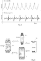
- the dynamic pressure monitoring can provide information on changes in the bladder, see Fig. 3 .
- a bladder accumulator fails as a rule spontaneously due to the bursting of the bladder. The extent to which the bursting of the bubble is noticeable through gas or liquid leakage remains to be seen. In any case, the filling pressure drops spontaneously.
- the specified measuring system can be easily and advantageously integrated into an existing condition monitoring system of a printing system, for example a machine.
- the invention thus allows cost-effective monitoring of the above-mentioned bubble accumulator, which serves to improve the immunity to interference. Remote monitoring via a local network or the Internet is also possible.
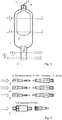
- the Fig. 1 shows a bladder accumulator according to the invention with a pressure vessel 1 which has a (gas) bladder 2, an oil inlet 3, a gas inlet 4 and a pressure sensor 5, a first temperature sensor 6 and two further temperature sensors 8 and 9.
- the gas inlet 4 has a gas valve 15 covered by a protective cap 14. It should be noted that a pressure measurement can also be carried out here.
- the arrangement is designed to measure not only the pressure and the temperature at the media inlet 3 but also the temperature at at least two points, in the middle and at the upper end of the memory, and at evaluation units 7 for the pressure and 11 for the pressure (not shown) to transfer various temperature measuring points.
- This arrangement according to the invention can be implemented cost-effectively and is easy to assemble.
- the Fig. 2 shows the necessary sensors.
- Three temperature sensors of the type PT100 and one pressure sensor PT5301 from the applicant are shown. Of course, similar sensors from other manufacturers can also be used.
- converters marked 10 are required (PT100 - temperature sensor on 4-20 mA).
- Fig. 3 shows typical pressure curves with intact and without or with burst bladder. As you can easily see, a burst bubble is easily recognizable from the pressure curve. However, damage to the bladder, leaks and material fatigue should be detected at an early stage (predictive maintenance).
- the Fig. 4 shows the sensors from the Fig. 2 evaluation units to be connected.
- the signals of the pressure sensor 5 are evaluated by a diagnostic unit labeled 7 for vibration sensors of the type VSE100 from the applicant.
- the signals from the three temperature sensors are fed to an AS-Interface switch cabinet module of the type AC3222 designated by 11 from the applicant.
- An AS-Interface power supply of the type AC1258 from the applicant serves as the power supply unit 13.
- the evaluation units 7 and 11 are connected to an IO-Link master with Ethernet / IP interface AL1920 from the applicant. It is denoted by 12 and is used for communication with the outside world, in particular with higher-level control units. The cabling familiar to the person skilled in the art is not explicitly shown.
- the evaluation units 7 and / or 11 contain parameter sets for the sensors as well as the software necessary for their evaluation and for carrying out the evaluation method according to the invention, the evaluation being able to take place in a higher-level control and evaluation unit.
Landscapes
- Engineering & Computer Science (AREA)
- Physics & Mathematics (AREA)
- Fluid Mechanics (AREA)
- Mechanical Engineering (AREA)
- General Engineering & Computer Science (AREA)
- Supply Devices, Intensifiers, Converters, And Telemotors (AREA)
- Examining Or Testing Airtightness (AREA)
Abstract
Description
- Die Erfindung betrifft einen hydropneumatischen Blasenspeicher gemäß Anspruch 1, ein Verfahren zu dessen Überwachung gemäß Anspruch 5 sowie dessen Verwendung gemäß Anspruch 6.
Unter einem Blasenspeicher wird ein spezieller hydropneumatischer Speicher verstanden, bei dem eine flexible Blase als Trennglied zwischen einem kompressiblen Gaspolster und einem auch als Betriebsflüssigkeit bezeichneten strömungsfähigen Medium fungiert.
Als Betriebsflüssigkeit kommen Druckmittel in hydraulischen Anlagen wie Hydrauliköl oder sonstige Druckfluide, aber auch Schmier- oder Kühlmittel in Frage.
Die Speicher bestehen aus einem Druckbehälter und der oben genannten Speicherblase, sowie aus den für die gas- und mediumseitigen Anschlüsse notwendigen Armaturen.
Derartige Hydrospeicher werden von den meisten namhaften Hydraulikherstellern angeboten. - Die
DE 10 2009 010 775 A1 beschreibt einen Hydrospeicher zur Aufnahme mindestens eines Teilvolumens einer unter Druck stehenden Flüssigkeit, wobei der Hydrospeicher ein Gehäuse mit mindestens einer Anschlussstelle an eine Hydraulikeinrichtung, wie einen Hydraulikkreis, aufweist. Ein Datenspeicher ist Bestandteil des Hydrospeichers und ist mittels eines außerhalb des Hydrospeichers angeordneten Lese- und/oder Schreibgerätes auslesbar.
In einer Ausführungsart ist in dem Gehäuse des Hydrospeichers ein Trennelement angeordnet, durch das zwei Arbeitsräume voneinander getrennt sind. Der Datenspeicher kann einen Sensor zur Erfassung des Drucks und/oder der Temperatur aufweisen. Im Falle eines Drucksensors kann der Druck im Gasraum ermittelt und ein Warnsignal an das zugeordnete Lese- und/oder Schreibgerät oder eine Steuereinrichtung gesendet werden, wenn der Druck einen vorgebbaren Wert unter- und/oder überschreitet. - Die
DE 10 2011 100 532 A1 beschreibt unter anderem einen Blasenspeicher, bei dem der Übertritt zumindest eines Mediums über die Trenneinrichtung in den anderen Medienraum detektierbar sein soll. Eine zur Dichtheitsprüfung dienende Messeinrichtung soll mindestens einen auf der Gasseite angeordneten Sensor aufweisen.
Neben thermischen Sensoren zur Bestimmung der Wärmeleitfähigkeit werden auch optische Messverfahren wie Streulichtmessungen oder die Bestimmung der Lumineszenz, die Messung der elektrischen Leitfähigkeit, der dielektrischen Eigenschaften, chemische oder physikalische Messverfahren, wie die Messung des Schwingungsverhaltendes Mediums, vorgeschlagen. Als nachteilig werden der teilweise enorme Messaufwand, sowie die bei den angegebenen Messverfahren notwendigen Anpassungen an das Medium, d. h. den Betriebsstoff, angesehen. - Die Aufgabe der Erfindung wird darin gesehen, den Messaufwand gering zu halten und eine für möglichst alle in Frage kommenden Betriebsstoffe geeignete Messeinrichtung anzugeben. Außerdem soll die Anordnung preisgünstig, leicht zu handhaben und zumindest teilweise auch außerhalb der Medien angeordnet sein können. Insbesondere sollen auch "schleichende" Veränderungen erkannt werden (predictive mainteneance).
- Die Aufgabe der Erfindung wird mit den Merkmalen des Anspruchs 1 gelöst. Der Anspruch 5 beschreibt das erfindungsgemäße Verfahren. Die abhängigen Ansprüche betreffen vorteilhafte Ausgestaltungen der Erfindung. Anspruch 6 betrifft die Verwendung des Blasenspeichers.
- Der wesentliche Erfindungsgedanke besteht darin, auf oftmals ohnehin vorhandene Druck- und/oder Temperatursensoren zurückzugreifen und diese derart anzuordnen und auszuwerten, dass eine Beschädigung, insbesondere die Ermüdung der Blase, durch einen mit den Sensoren verbundenen Auswerteeinheit erkennbar wird.
- Dazu sind mindestens ein Drucksensor und mindestens drei Temperatursensoren vorgesehen. Erfindungsgemäß ist der Drucksensor entweder auf der Gasseite oder auf der Medienseite (Ölseite) angeordnet, ein erster Temperatursensor ist an einer Armatur und die beiden anderen Temperatursensoren sind in unterschiedlicher Höhe an oder im Blasenspeicher angeordnet. Gemäß dem erfindungsgemäßen Verfahren werden der Mediendruck und/oder der Gasdruck, die Medientemperatur und eine Temperaturdifferenz im Bereich der Blase bestimmt, wobei die Auswertung durch den Vergleich mit Sollwerten erfolgt.
- Die folgenden Ausführungen dienen zur Erläuterung des erfindungsgemäßen Verfahrens. Der Ausfall eines Druckspeichers macht sich u. a. dadurch bemerkbar, dass in einem spezifischen Druckbereich die notwendige Flüssigkeitsmenge nicht mehr aufgenommen oder abgegeben werden kann, wobei der Ausfall oftmals durch einen falschen Gasdruck verursacht wird. Somit können durch eine permanente statische und dynamische Überwachung des Fülldrucks Ausfälle vermieden und die Lebensdauer der Anlage durch vorausschauende Überwachung und einer damit verbundenen Wartung (predictive mainteneance) verlängert werden.
- Da der statisch gemessene Druck lediglich angibt, ob sich der Fülldruck in einem erlaubten Bereich befindet, kann die dynamische Drucküberwachung Hinweise auf Veränderungen der Blase geben, siehe
Fig. 3 .
Allerdings treten im Gegensatz zu einem Kolbenspeicher bei einem Blasenspeicher Ausfälle in der Regel spontan durch Platzen der Blase auf. Inwieweit sich das Platzen der Blase durch Gas- oder Flüssigkeitsleckagen bemerkbar macht, sei zunächst dahingestellt. Jedenfalls fällt der Fülldruck spontan ab. - Ein weiteres Indiz für die Veränderung der Blase sind Temperaturdifferenzen insbesondere zwischen dem Gas- oder Öleinlass und dem Behälter bzw. in der Blase. Deshalb werden drei erfindungsgemäß angeordnete permanent ausgewertete Temperatursensoren vorgeschlagen, um ein sich langsam änderndes Temperaturverhalten zu erkennen (predictive maintenance).
- Für einen zyklisch betriebenen Blasenspeicher wird als Diagnosekonzept vorgeschlagen:
- 1. Erfassung der Anzahl der zyklischen Druckveränderungen (Zyklen)
- 2. Erfassung der Zeit zwischen den einzelnen Zyklen
- 3. Messung der Temperatur am Einlass, in der Mitte und am oberen Ende des Speichers
- 4. Statische Druckmessung, Prüfung, ob sich der Druck im Soll-Bereich befindet
- 5. Dynamische Druckmessung zur Erfassung der Zeit zwischen den einzelnen Zyklen
- 6. Dynamische Druckmessung zur Erkennung von Veränderungen an der Blase.
- Das angegebene Messsystem kann ohne weiteres vorteilhaft in ein vorhandenes Condition Monitoring System einer Druck-Anlage, beispielsweise einer Maschine, eingebunden werden.
- Weitere Vorteile der Erfindung bestehen darin, dass bereits vorhandene Drucksensoren oder Temperatursensoren verwendet und die vorgeschlagenen zusätzlichen Temperatursensoren leicht und ohne Medienkontakt am/im Gehäuse des Druckbehälters montiert werden können.
- Eine separate Auswerteeinheit ist in der Regel nicht notwendig, weil meistens vorhandene Steuereinheiten verwendet werden können. Somit erlaubt die Erfindung eine kostengünstige Überwachung des genannten Blasenspeichers, was zur Verbesserung der Störsicherheit dient. Eine Fernüberwachung über ein lokales Netzwerk oder das Internet ist ebenfalls möglich.
- Die Erfindung wird anhand der Zeichnung näher erläutert:
-
Fig.1 zeigt einen erfindungsgemäßen Blasenspeicher in teilweise geschnittener Darstellung -
Fig. 2 zeigt eine Auswahl der benötigten Druck- und Temperatursensoren -
Fig. 3 zeigt typische Druckverläufe mit intakter Blase und ohne (bzw. mit geplatzter) Blase -
Fig. 4 zeigt die mit den Sensoren ausFig. 2 verbundenen Auswerteeinheiten schematisch. - Die
Fig. 1 zeigt einen erfindungsgemäßen Blasenspeicher mit einem Druckbehälter 1, der eine (Gas-) Blase 2, einen Öleinlass 3, einen Gaseinlass 4 und einen Drucksensor 5, einen ersten Temperatursensor 6 und zwei weitere Temperatursensoren 8 und 9 aufweist.
Der Gaseinlass 4 weist ein von einer Schutzkappe 14 bedecktes Gasventil 15 auf. Es wird darauf hingewiesen, dass auch hier eine Druckmessung vorgenommen werden kann. - Die Anordnung wird erfindungsgemäß dazu ausgebildet, neben dem Druck und der Temperatur am Medieneinlass 3 auch die Temperatur an mindestens zwei Stellen, in der Mitte und am oberen Ende des Speichers, zu messen, und an nicht dargestellte Auswerteeinheiten 7 für den Druck und 11 für die diversen Temperaturmessstellen zu übertragen. Diese erfindungsgemäße Anordnung ist kostengünstig realisierbar und leicht zu montieren.
- Durch Alterung der Blase 2 mit erhöhter Diffusion bzw. durch Beschädigung derselben können Mikroleckagen oder Durchbrüche des Öls in das Gasreservoir hin stattfinden. Sobald das Öl damit auf das Level von Temperatursensor 8 intern ansteigt und das Gas mehr und mehr zurückgedrängt wird, ergibt sich dort ein neues Temperaturniveau, das indirekt auf diese Problemstellung hinweist. Gleichzeitig nimmt die "Elastizität" der Gesamtanlage durch einen sich verringernden Gasvorrat ab, was die Dynamik wesentlich verändert und was sich in einem deutlich unterschiedlichen Drucksignal (siehe
Fig. 3 ) zeigt. Somit kann durch die Überlagerung dieser beiden Effekt aus minimierter Druckdynamik und sich verändernde bzw. minimierenden Temperaturdifferenzen der beiden oberen Temperatursensoren 8, 9 zum originären unteren Temperatursensor 6 für die Hydraulikflüssigkeit eine eindeutige und klare Erkennung des zunehmenden Zurückdrängens des Gasvolumens und damit einem zunehmend fehlendem Dämpfungsverhalten und einer damit einhergehenden Überbeanspruchung der Maschine durch fehlende Dämpfung bzw. Ausgleichs von Maschinen- und Pumpendynamiken erkannt werden. - Die
Fig. 2 zeigt die notwendigen Sensoren. Es sind drei Temperatursensoren des Typs PT100 und ein Drucksensor PT5301 der Anmelderin dargestellt. Natürlich können auch ähnliche Sensoren andere Hersteller Verwendung finden. Für die drei PT100-Temperatursensoren sind mit 10 bezeichnete Umsetzer (PT100 - Temperatursensor auf 4-20 mA) erforderlich. -
Fig. 3 zeigt typische Druckverläufe mit intakter und ohne bzw. mit geplatzter Blase. Wie man unschwer erkennt, ist eine geplatzte Blase anhand des Druckverlaufs ohne weiteres erkennbar. Allerdings sollen Beschädigungen der Blase, Undichtigkeiten und Materialermüdung bereits frühzeitig erkannt werden (predictive maintenance). - Die
Fig. 4 zeigt die mit dem Sensoren aus derFig. 2 zu verbindenden Auswerteeinheiten. Die Signale des Drucksensors 5 werden von einer mit 7 bezeichneten Diagnoseeinheit für Schwingungssensoren des Typs VSE100 der Anmelderin ausgewertet.
Die Signale der drei Temperatursensoren werden einem mit 11 bezeichneten AS-Interface Schaltschrankmodul des Typs AC3222 der Anmelderin zugeführt.
Als Netzteil 13 dient eine AS-Interface Stromversorgung des Typs AC1258 der Anmelderin. Die Auswerteeinheiten 7 und 11 sind mit einem IO-Link Master mit Ethernet/IP-Schnittstelle AL1920 der Anmelderin verbunden. Sie ist mit 12 bezeichnet und dient zur Kommunikation mit der Außenwelt, insbesondere mit übergeordneten Steuereinheiten.
Die dem Fachmann geläufige Verkabelung ist nicht explizit dargestellt. - Da sich diese Anordnung dem Fachmann ohne weiteres erschließt, kann die Erläuterung kurz gehalten werden.
Die Auswerteeinheiten 7 und/oder 11 enthalten Parametersätze für die Sensoren sowie die zu deren Auswertung und zur Durchführung des erfindungsgemäßen Auswerteverfahrens notwendige Software, wobei die Auswertung genauso in einer übergeordneten Steuer- und Auswerteeinheit erfolgen kann. -
- 1
- Druckbehälter
- 2
- Blase (Gasblase)
- 3
- Öleinlass / Medieneinlass
- 4
- Gaseinlass
- 5
- Drucksensor, beispielsweise ein PT5301 der Anmelderin
- 6
- Erster Temperatursensor (für das Medium), z. B. ein PT100
- 7
- Auswerteeinheit, z. B eine VSE 100 der Anmelderin für bis zu 6 Sensoren
- 8
- Zweiter Temperatursensor (für die Gasblase), z. B. ein PT100
- 9
- Dritter Temperatursensor (für die Gasblase), z. B. ein PT100
- 10
- Umsetzer PT100 - Temperatursensor auf 4-20 mA (3x)
- 11
- Schaltschrank, beispielsweise ein AS-Interface Schaltschrankmodul AC3222
- 12
- Ethernet Switch, z. B. ein IO-Link Master mit Ehernet/IP Schnittstelle AL1920
- 13
- Netzteil, beispielsweise eine AS-Interface Stromversorgung AC1258
- 14
- Abschlusskappe
- 15
- Gasventil
Claims (6)
- Hydropneumatischer Blasenspeicher mit einem Druckbehälter (1), der eine Blase (2), einen Öleinlass (3), einen Gaseinlass (4) und einen Drucksensor (5), mindestens einen Temperatursensor (6) und Auswerteeinheiten (7, 11) für Druck und Temperatur aufweist, dadurch gekennzeichnet, dass er dazu ausgebildet ist, Temperaturen an mindestens zwei weiteren Stellen mit zwei weiteren Temperatursensoren (8, 9) zu messen und sowohl einen zeitlichen Druckverlauf als auch die Temperaturdifferenz im Speicher zu erfassen und mit Sollwerten zu vergleichen.
- Hydropneumatischer Blasenspeicher gemäß Anspruch 1, dadurch gekennzeichnet, dass Öldruck erfasst und ausgewertet wird.
- Hydropneumatischer Blasenspeicher gemäß Anspruch 1, dadurch gekennzeichnet, dass der Gasdruck erfasst und ausgewertet wird.
- Hydropneumatischer Blasenspeicher gemäß Anspruch 1, dadurch gekennzeichnet, dass die Differenz aus Öl- und Gasdruck erfasst und ausgewertet wird.
- Verfahren zur Überwachung eines hydropneumatischer Blasenspeichers gemäß einem der Ansprüche 1 bis 4 mit den folgenden Verfahrensschritten:- Erfassung der Anzahl der zyklischen Druckveränderungen (Zyklen)- Erfassung der Zeit zwischen den einzelnen Zyklen- Messung der Temperatur am Einlass, in der Mitte und am Ende des Speichers- Statische Druckmessung, Prüfung, ob sich der Druck im Soll-Bereich befindet- Dynamische Druckmessung zur Erfassung der Zeit zwischen den einzelnen Zyklen- Dynamische Druckmessung zur Erkennung von Veränderungen an der Blase.
- Verwendung eines hydropneumatischen Blasenspeichers gemäß einem der Ansprüche 1 bis 4 in einer Maschine.
Applications Claiming Priority (1)
| Application Number | Priority Date | Filing Date | Title |
|---|---|---|---|
| DE102020104040.7A DE102020104040B3 (de) | 2020-02-17 | 2020-02-17 | Überwachter hydropneumatischer Blasenspeicher |
Publications (2)
| Publication Number | Publication Date |
|---|---|
| EP3869045A1 true EP3869045A1 (de) | 2021-08-25 |
| EP3869045B1 EP3869045B1 (de) | 2022-05-11 |
Family
ID=74495365
Family Applications (1)
| Application Number | Title | Priority Date | Filing Date |
|---|---|---|---|
| EP21156935.5A Active EP3869045B1 (de) | 2020-02-17 | 2021-02-12 | Überwachter hydropneumatischer blasenspeicher |
Country Status (3)
| Country | Link |
|---|---|
| EP (1) | EP3869045B1 (de) |
| DE (1) | DE102020104040B3 (de) |
| ES (1) | ES2923388T3 (de) |
Families Citing this family (3)
| Publication number | Priority date | Publication date | Assignee | Title |
|---|---|---|---|---|
| DE102021102991B3 (de) | 2021-02-09 | 2022-02-10 | Ifm Electronic Gmbh | Verfahren zum Betreiben eines hydropneumatischen Blasenspeichers |
| EP4092276A1 (de) * | 2021-05-21 | 2022-11-23 | Roth Hydraulics GmbH | Verfahren zur zustandsüberwachung eines hydraulikspeichers und hydraulikspeicher |
| CN113217503A (zh) * | 2021-05-27 | 2021-08-06 | 中冶赛迪技术研究中心有限公司 | 一种液压系统蓄能器状态检测系统 |
Citations (4)
| Publication number | Priority date | Publication date | Assignee | Title |
|---|---|---|---|---|
| DE102009010775A1 (de) | 2009-02-26 | 2010-09-30 | Hydac Technology Gmbh | Hydrospeicher, Hydraulikeinrichtung mit einem solchen Hydrospeicher und zughörige Datenübertragungsvorrichtung |
| DE102009032859A1 (de) * | 2009-07-13 | 2011-01-20 | Robert Bosch Gmbh | Vorrichtung, Verfahren zur Ermittlung einer Verschleißgröße oder einer Restlebensdauer eines Hydrospeichers sowie entsprechender Hydrospeicher |
| DE102011100532A1 (de) | 2011-05-05 | 2012-11-08 | Hydac Technology Gmbh | Medientrennvorrichtung, insbesondere Hydrospeicher einschließlich zugehöriger Messeinrichtung und Messverfahren |
| EP2647849A2 (de) * | 2012-04-02 | 2013-10-09 | MARCO SYSTEMANALYSE UND ENTWICKLUNG GmbH | Positionsbestimmungsvorrichtung |
Family Cites Families (1)
| Publication number | Priority date | Publication date | Assignee | Title |
|---|---|---|---|---|
| DE10035944A1 (de) * | 2000-07-21 | 2002-02-28 | Hans Heynen | Verfahren zur Messung des Gasdruckes in Gasfeder- oder Gasspeicherkugeln |
-
2020
- 2020-02-17 DE DE102020104040.7A patent/DE102020104040B3/de not_active Expired - Fee Related
-
2021
- 2021-02-12 EP EP21156935.5A patent/EP3869045B1/de active Active
- 2021-02-12 ES ES21156935T patent/ES2923388T3/es active Active
Patent Citations (4)
| Publication number | Priority date | Publication date | Assignee | Title |
|---|---|---|---|---|
| DE102009010775A1 (de) | 2009-02-26 | 2010-09-30 | Hydac Technology Gmbh | Hydrospeicher, Hydraulikeinrichtung mit einem solchen Hydrospeicher und zughörige Datenübertragungsvorrichtung |
| DE102009032859A1 (de) * | 2009-07-13 | 2011-01-20 | Robert Bosch Gmbh | Vorrichtung, Verfahren zur Ermittlung einer Verschleißgröße oder einer Restlebensdauer eines Hydrospeichers sowie entsprechender Hydrospeicher |
| DE102011100532A1 (de) | 2011-05-05 | 2012-11-08 | Hydac Technology Gmbh | Medientrennvorrichtung, insbesondere Hydrospeicher einschließlich zugehöriger Messeinrichtung und Messverfahren |
| EP2647849A2 (de) * | 2012-04-02 | 2013-10-09 | MARCO SYSTEMANALYSE UND ENTWICKLUNG GmbH | Positionsbestimmungsvorrichtung |
Also Published As
| Publication number | Publication date |
|---|---|
| ES2923388T3 (es) | 2022-09-27 |
| DE102020104040B3 (de) | 2021-02-25 |
| EP3869045B1 (de) | 2022-05-11 |
Similar Documents
| Publication | Publication Date | Title |
|---|---|---|
| EP3869045B1 (de) | Überwachter hydropneumatischer blasenspeicher | |
| EP2705257B1 (de) | Medientrennvorrichtung, insbesondere hydrospeicher, einschliesslich zugehöriger messeinrichtung und messverfahren | |
| EP3100015B1 (de) | Verfahren zum betreiben eines druckmessumformers sowie druckmessumformer | |
| DE102008020862B3 (de) | Messumformer zur Prozessinstrumentierung und Verfahren zur Überwachung des Zustands dessen Sensors | |
| DE102009005767B4 (de) | Motorsystem und Verfahren zur Ölzustandsdetektion | |
| WO2008031658A1 (de) | Verfahren und vorrichtung zur diagnose von flüssigkeitsverlusten in mit druck übertragenden flüssigkeiten gefüllten druckmessaufnehmern | |
| EP4039988B1 (de) | Verfahren zum betreiben eines hydropneumatischen blasenspeichers | |
| EP2080001A2 (de) | Druckmessgerät | |
| EP3026412A2 (de) | Druckanzeigeeinrichtung | |
| DE102015206403B4 (de) | Hydraulische Anordnung und Verfahren zur Leckagemessung für eine hydraulische Anordnung | |
| DE102005052640B3 (de) | Verfahren und Vorrichtung zur Online-Überwachung des Speichervorfülldruckes bei Hydrospeichern | |
| DE2906897C2 (de) | ||
| EP0585280B1 (de) | Verfahren zum messen des druckes eines gases in einem gasdruckspeicher und vorrichtung zum durchführen desselben | |
| DE102019211493A1 (de) | Verfahren zum Entlüften eines Kühlkreislaufs, Set einer Kühlmittelausgleichsanordnung und Kraftfahrzeug | |
| WO2012098136A1 (de) | Druckmessumformer | |
| DE102009032859A1 (de) | Vorrichtung, Verfahren zur Ermittlung einer Verschleißgröße oder einer Restlebensdauer eines Hydrospeichers sowie entsprechender Hydrospeicher | |
| DE102011111558A1 (de) | Trockener Messwertaufnehmer | |
| EP2725241A1 (de) | Verfahren und Vorrichtung zur Bestimmung des Füllstandes eines Volumens | |
| DE69325190T2 (de) | Verfahren und Vorrichtung zur Erkennung von ungelöstes Gaz in hydraulische Systemen | |
| DE102022124706A1 (de) | Verfahren zum Betreiben eines Membranventils und Membranventil | |
| DE102005023410B4 (de) | Verfahren zur Erfassung von in der Hydraulikflüssigkeit eines hydraulischen Kreislaufs eingeschlossenem Gas | |
| DE102010035965A1 (de) | Druckmessumformer | |
| WO2022042918A1 (de) | Verfahren und anordnung zur durchflussmessung | |
| DE102013107535A1 (de) | Druckmittlersystem mit einem Druckmittler und Verfahren zum Erkennen eines Membranbruches | |
| DE102013113690A1 (de) | Druckmessgerät und Verfahren zu dessen Inbetriebnahme an einem Einsatzort |
Legal Events
| Date | Code | Title | Description |
|---|---|---|---|
| PUAI | Public reference made under article 153(3) epc to a published international application that has entered the european phase |
Free format text: ORIGINAL CODE: 0009012 |
|
| STAA | Information on the status of an ep patent application or granted ep patent |
Free format text: STATUS: REQUEST FOR EXAMINATION WAS MADE |
|
| 17P | Request for examination filed |
Effective date: 20210212 |
|
| AK | Designated contracting states |
Kind code of ref document: A1 Designated state(s): AL AT BE BG CH CY CZ DE DK EE ES FI FR GB GR HR HU IE IS IT LI LT LU LV MC MK MT NL NO PL PT RO RS SE SI SK SM TR |
|
| GRAP | Despatch of communication of intention to grant a patent |
Free format text: ORIGINAL CODE: EPIDOSNIGR1 |
|
| STAA | Information on the status of an ep patent application or granted ep patent |
Free format text: STATUS: GRANT OF PATENT IS INTENDED |
|
| INTG | Intention to grant announced |
Effective date: 20220222 |
|
| GRAS | Grant fee paid |
Free format text: ORIGINAL CODE: EPIDOSNIGR3 |
|
| GRAA | (expected) grant |
Free format text: ORIGINAL CODE: 0009210 |
|
| STAA | Information on the status of an ep patent application or granted ep patent |
Free format text: STATUS: THE PATENT HAS BEEN GRANTED |
|
| AK | Designated contracting states |
Kind code of ref document: B1 Designated state(s): AL AT BE BG CH CY CZ DE DK EE ES FI FR GB GR HR HU IE IS IT LI LT LU LV MC MK MT NL NO PL PT RO RS SE SI SK SM TR |
|
| REG | Reference to a national code |
Ref country code: GB Ref legal event code: FG4D Free format text: NOT ENGLISH |
|
| REG | Reference to a national code |
Ref country code: CH Ref legal event code: EP |
|
| REG | Reference to a national code |
Ref country code: AT Ref legal event code: REF Ref document number: 1491632 Country of ref document: AT Kind code of ref document: T Effective date: 20220515 |
|
| REG | Reference to a national code |
Ref country code: DE Ref legal event code: R096 Ref document number: 502021000029 Country of ref document: DE |
|
| REG | Reference to a national code |
Ref country code: IE Ref legal event code: FG4D Free format text: LANGUAGE OF EP DOCUMENT: GERMAN |
|
| REG | Reference to a national code |
Ref country code: LT Ref legal event code: MG9D |
|
| REG | Reference to a national code |
Ref country code: NL Ref legal event code: MP Effective date: 20220511 |
|
| REG | Reference to a national code |
Ref country code: ES Ref legal event code: FG2A Ref document number: 2923388 Country of ref document: ES Kind code of ref document: T3 Effective date: 20220927 |
|
| PG25 | Lapsed in a contracting state [announced via postgrant information from national office to epo] |
Ref country code: SE Free format text: LAPSE BECAUSE OF FAILURE TO SUBMIT A TRANSLATION OF THE DESCRIPTION OR TO PAY THE FEE WITHIN THE PRESCRIBED TIME-LIMIT Effective date: 20220511 Ref country code: PT Free format text: LAPSE BECAUSE OF FAILURE TO SUBMIT A TRANSLATION OF THE DESCRIPTION OR TO PAY THE FEE WITHIN THE PRESCRIBED TIME-LIMIT Effective date: 20220912 Ref country code: NO Free format text: LAPSE BECAUSE OF FAILURE TO SUBMIT A TRANSLATION OF THE DESCRIPTION OR TO PAY THE FEE WITHIN THE PRESCRIBED TIME-LIMIT Effective date: 20220811 Ref country code: NL Free format text: LAPSE BECAUSE OF FAILURE TO SUBMIT A TRANSLATION OF THE DESCRIPTION OR TO PAY THE FEE WITHIN THE PRESCRIBED TIME-LIMIT Effective date: 20220511 Ref country code: LT Free format text: LAPSE BECAUSE OF FAILURE TO SUBMIT A TRANSLATION OF THE DESCRIPTION OR TO PAY THE FEE WITHIN THE PRESCRIBED TIME-LIMIT Effective date: 20220511 Ref country code: HR Free format text: LAPSE BECAUSE OF FAILURE TO SUBMIT A TRANSLATION OF THE DESCRIPTION OR TO PAY THE FEE WITHIN THE PRESCRIBED TIME-LIMIT Effective date: 20220511 Ref country code: GR Free format text: LAPSE BECAUSE OF FAILURE TO SUBMIT A TRANSLATION OF THE DESCRIPTION OR TO PAY THE FEE WITHIN THE PRESCRIBED TIME-LIMIT Effective date: 20220812 Ref country code: FI Free format text: LAPSE BECAUSE OF FAILURE TO SUBMIT A TRANSLATION OF THE DESCRIPTION OR TO PAY THE FEE WITHIN THE PRESCRIBED TIME-LIMIT Effective date: 20220511 Ref country code: BG Free format text: LAPSE BECAUSE OF FAILURE TO SUBMIT A TRANSLATION OF THE DESCRIPTION OR TO PAY THE FEE WITHIN THE PRESCRIBED TIME-LIMIT Effective date: 20220811 |
|
| PG25 | Lapsed in a contracting state [announced via postgrant information from national office to epo] |
Ref country code: RS Free format text: LAPSE BECAUSE OF FAILURE TO SUBMIT A TRANSLATION OF THE DESCRIPTION OR TO PAY THE FEE WITHIN THE PRESCRIBED TIME-LIMIT Effective date: 20220511 Ref country code: PL Free format text: LAPSE BECAUSE OF FAILURE TO SUBMIT A TRANSLATION OF THE DESCRIPTION OR TO PAY THE FEE WITHIN THE PRESCRIBED TIME-LIMIT Effective date: 20220511 Ref country code: LV Free format text: LAPSE BECAUSE OF FAILURE TO SUBMIT A TRANSLATION OF THE DESCRIPTION OR TO PAY THE FEE WITHIN THE PRESCRIBED TIME-LIMIT Effective date: 20220511 Ref country code: IS Free format text: LAPSE BECAUSE OF FAILURE TO SUBMIT A TRANSLATION OF THE DESCRIPTION OR TO PAY THE FEE WITHIN THE PRESCRIBED TIME-LIMIT Effective date: 20220911 |
|
| PG25 | Lapsed in a contracting state [announced via postgrant information from national office to epo] |
Ref country code: SM Free format text: LAPSE BECAUSE OF FAILURE TO SUBMIT A TRANSLATION OF THE DESCRIPTION OR TO PAY THE FEE WITHIN THE PRESCRIBED TIME-LIMIT Effective date: 20220511 Ref country code: SK Free format text: LAPSE BECAUSE OF FAILURE TO SUBMIT A TRANSLATION OF THE DESCRIPTION OR TO PAY THE FEE WITHIN THE PRESCRIBED TIME-LIMIT Effective date: 20220511 Ref country code: RO Free format text: LAPSE BECAUSE OF FAILURE TO SUBMIT A TRANSLATION OF THE DESCRIPTION OR TO PAY THE FEE WITHIN THE PRESCRIBED TIME-LIMIT Effective date: 20220511 Ref country code: EE Free format text: LAPSE BECAUSE OF FAILURE TO SUBMIT A TRANSLATION OF THE DESCRIPTION OR TO PAY THE FEE WITHIN THE PRESCRIBED TIME-LIMIT Effective date: 20220511 Ref country code: DK Free format text: LAPSE BECAUSE OF FAILURE TO SUBMIT A TRANSLATION OF THE DESCRIPTION OR TO PAY THE FEE WITHIN THE PRESCRIBED TIME-LIMIT Effective date: 20220511 Ref country code: CZ Free format text: LAPSE BECAUSE OF FAILURE TO SUBMIT A TRANSLATION OF THE DESCRIPTION OR TO PAY THE FEE WITHIN THE PRESCRIBED TIME-LIMIT Effective date: 20220511 |
|
| REG | Reference to a national code |
Ref country code: DE Ref legal event code: R097 Ref document number: 502021000029 Country of ref document: DE |
|
| PLBE | No opposition filed within time limit |
Free format text: ORIGINAL CODE: 0009261 |
|
| STAA | Information on the status of an ep patent application or granted ep patent |
Free format text: STATUS: NO OPPOSITION FILED WITHIN TIME LIMIT |
|
| PG25 | Lapsed in a contracting state [announced via postgrant information from national office to epo] |
Ref country code: AL Free format text: LAPSE BECAUSE OF FAILURE TO SUBMIT A TRANSLATION OF THE DESCRIPTION OR TO PAY THE FEE WITHIN THE PRESCRIBED TIME-LIMIT Effective date: 20220511 |
|
| 26N | No opposition filed |
Effective date: 20230214 |
|
| PG25 | Lapsed in a contracting state [announced via postgrant information from national office to epo] |
Ref country code: MC Free format text: LAPSE BECAUSE OF FAILURE TO SUBMIT A TRANSLATION OF THE DESCRIPTION OR TO PAY THE FEE WITHIN THE PRESCRIBED TIME-LIMIT Effective date: 20220511 |
|
| REG | Reference to a national code |
Ref country code: BE Ref legal event code: MM Effective date: 20230228 |
|
| PG25 | Lapsed in a contracting state [announced via postgrant information from national office to epo] |
Ref country code: LU Free format text: LAPSE BECAUSE OF NON-PAYMENT OF DUE FEES Effective date: 20230212 |
|
| REG | Reference to a national code |
Ref country code: IE Ref legal event code: MM4A |
|
| PG25 | Lapsed in a contracting state [announced via postgrant information from national office to epo] |
Ref country code: IE Free format text: LAPSE BECAUSE OF NON-PAYMENT OF DUE FEES Effective date: 20230212 |
|
| PG25 | Lapsed in a contracting state [announced via postgrant information from national office to epo] |
Ref country code: BE Free format text: LAPSE BECAUSE OF NON-PAYMENT OF DUE FEES Effective date: 20230228 |
|
| REG | Reference to a national code |
Ref country code: CH Ref legal event code: PL |
|
| PG25 | Lapsed in a contracting state [announced via postgrant information from national office to epo] |
Ref country code: CH Free format text: LAPSE BECAUSE OF NON-PAYMENT OF DUE FEES Effective date: 20240229 |
|
| PG25 | Lapsed in a contracting state [announced via postgrant information from national office to epo] |
Ref country code: CH Free format text: LAPSE BECAUSE OF NON-PAYMENT OF DUE FEES Effective date: 20240229 |
|
| PG25 | Lapsed in a contracting state [announced via postgrant information from national office to epo] |
Ref country code: BG Free format text: LAPSE BECAUSE OF FAILURE TO SUBMIT A TRANSLATION OF THE DESCRIPTION OR TO PAY THE FEE WITHIN THE PRESCRIBED TIME-LIMIT Effective date: 20220511 |
|
| PG25 | Lapsed in a contracting state [announced via postgrant information from national office to epo] |
Ref country code: BG Free format text: LAPSE BECAUSE OF FAILURE TO SUBMIT A TRANSLATION OF THE DESCRIPTION OR TO PAY THE FEE WITHIN THE PRESCRIBED TIME-LIMIT Effective date: 20220511 |
|
| PGFP | Annual fee paid to national office [announced via postgrant information from national office to epo] |
Ref country code: AT Payment date: 20250417 Year of fee payment: 5 |
|
| PG25 | Lapsed in a contracting state [announced via postgrant information from national office to epo] |
Ref country code: CY Free format text: LAPSE BECAUSE OF FAILURE TO SUBMIT A TRANSLATION OF THE DESCRIPTION OR TO PAY THE FEE WITHIN THE PRESCRIBED TIME-LIMIT; INVALID AB INITIO Effective date: 20210212 |
|
| PG25 | Lapsed in a contracting state [announced via postgrant information from national office to epo] |
Ref country code: HU Free format text: LAPSE BECAUSE OF FAILURE TO SUBMIT A TRANSLATION OF THE DESCRIPTION OR TO PAY THE FEE WITHIN THE PRESCRIBED TIME-LIMIT; INVALID AB INITIO Effective date: 20210212 |
|
| PG25 | Lapsed in a contracting state [announced via postgrant information from national office to epo] |
Ref country code: TR Free format text: LAPSE BECAUSE OF FAILURE TO SUBMIT A TRANSLATION OF THE DESCRIPTION OR TO PAY THE FEE WITHIN THE PRESCRIBED TIME-LIMIT Effective date: 20220511 |
|
| PG25 | Lapsed in a contracting state [announced via postgrant information from national office to epo] |
Ref country code: SI Free format text: LAPSE BECAUSE OF FAILURE TO SUBMIT A TRANSLATION OF THE DESCRIPTION OR TO PAY THE FEE WITHIN THE PRESCRIBED TIME-LIMIT Effective date: 20220511 |
|
| PGFP | Annual fee paid to national office [announced via postgrant information from national office to epo] |
Ref country code: GB Payment date: 20260219 Year of fee payment: 6 |
|
| PGFP | Annual fee paid to national office [announced via postgrant information from national office to epo] |
Ref country code: ES Payment date: 20260319 Year of fee payment: 6 |
|
| PGFP | Annual fee paid to national office [announced via postgrant information from national office to epo] |
Ref country code: DE Payment date: 20260217 Year of fee payment: 6 |
|
| PGFP | Annual fee paid to national office [announced via postgrant information from national office to epo] |
Ref country code: IT Payment date: 20260227 Year of fee payment: 6 |
|
| PGFP | Annual fee paid to national office [announced via postgrant information from national office to epo] |
Ref country code: FR Payment date: 20260223 Year of fee payment: 6 |
|
| PG25 | Lapsed in a contracting state [announced via postgrant information from national office to epo] |
Ref country code: CH Free format text: THE PATENT HAS BEEN ANNULLED BY A DECISION OF A NATIONAL AUTHORITY Effective date: 20240229 |
|
| PG25 | Lapsed in a contracting state [announced via postgrant information from national office to epo] |
Ref country code: MT Free format text: LAPSE BECAUSE OF NON-PAYMENT OF DUE FEES Effective date: 20230212 |