EP3868998A1 - Verbindung zweier bohrstrangglieder eines bohrstrangs zum erdbohren - Google Patents
Verbindung zweier bohrstrangglieder eines bohrstrangs zum erdbohren Download PDFInfo
- Publication number
- EP3868998A1 EP3868998A1 EP21167590.5A EP21167590A EP3868998A1 EP 3868998 A1 EP3868998 A1 EP 3868998A1 EP 21167590 A EP21167590 A EP 21167590A EP 3868998 A1 EP3868998 A1 EP 3868998A1
- Authority
- EP
- European Patent Office
- Prior art keywords
- drill string
- pull
- plug
- head
- lock
- Prior art date
- Legal status (The legal status is an assumption and is not a legal conclusion. Google has not performed a legal analysis and makes no representation as to the accuracy of the status listed.)
- Granted
Links
Images
Classifications
-
- E—FIXED CONSTRUCTIONS
- E21—EARTH OR ROCK DRILLING; MINING
- E21B—EARTH OR ROCK DRILLING; OBTAINING OIL, GAS, WATER, SOLUBLE OR MELTABLE MATERIALS OR A SLURRY OF MINERALS FROM WELLS
- E21B17/00—Drilling rods or pipes; Flexible drill strings; Kellies; Drill collars; Sucker rods; Cables; Casings; Tubings
- E21B17/02—Couplings; joints
- E21B17/04—Couplings; joints between rod or the like and bit or between rod and rod or the like
- E21B17/046—Couplings; joints between rod or the like and bit or between rod and rod or the like with ribs, pins, or jaws, and complementary grooves or the like, e.g. bayonet catches
- E21B17/0465—Couplings; joints between rod or the like and bit or between rod and rod or the like with ribs, pins, or jaws, and complementary grooves or the like, e.g. bayonet catches characterised by radially inserted locking elements
Definitions
- the invention relates to a system and a method for connecting two drill string members of a drill string for earth drilling and the use of a pull-off safety device when connecting two drill string members of a drill string for earth drilling.
- a drill head In the case of rod-based drilling in the ground, in particular for the production of so-called horizontal bores, which can run essentially parallel to or at a relatively small angle of inclination to the surface of the earth, a drill head is driven by a drill rod, the so-called drill string, from a drive device arranged on the surface or in a pit driven forward.
- the drill rods used here usually consist of individual, interconnected rod sections which - according to the drilling path - are gradually attached to the rear end of the drill rod that has already been drilled and connected to it.
- the rod sections can be connected by means of a threaded connection and / or a plug connection.
- a plug-in connection is described which - similar to a threaded connection - is based on helical projections / grooves running on a threaded plug with a circular cross section or in a corresponding threaded bushing, the projections / grooves being designed in such a way that the self-locking characteristic of a threaded connection is not occurs.
- the invention was based on the object of specifying an improved possibility for connecting two drill string members of a drill string for earth drilling, which in particular enables a simpler design and / or a safe and / or simple connection.
- the invention is based on the idea of specifying a possibility for connecting two drill string members which combines both a plug connection and a screw connection with one another.
- the two drill string members can be plugged into one another and an anti-pull device is used, which is exposed at the end and can be screwed.
- the invention provides a system for connecting two drill string members of a drill string for earth drilling, one drill string member having a plug element arranged at the end in the form of a plug and the other drill string member having a plug element arranged at the end in the form of a socket.
- the plug and socket are designed in such a way that the two drill string members have through holes that are aligned with one another, through which a pull-out lock can be inserted.
- the pull-off safety device has a head and an end spaced apart from the head, a thread being formed at the end of the pull-off safety device.
- the head and end of the peel-off safety device are spaced apart from one another in such a way that the end of the pull-off safety device is exposed at the end when the pull-off safety device is inserted into the through holes.
- the term “drill string” comprises a string which has an earth boring tool and a rod and which can be moved by means of an earth boring device or a drive device in order to drill an earth hole through the earth.
- linkage includes not only rigid, individual, directly or indirectly connected, linkage sections with linkage, but in particular all force transmission elements that can be used in an earth boring device.
- pipe section in the sense of the description comprises an element which extends along a longitudinal axis and which is part of the pipe or of a drill string for earth drilling.
- the rod section can be designed as an element arranged on the front side in the drill string with an assigned function (transmitter housing or the like) or as an element (only mechanically) extending the drill string as a rod section.
- the rod assembly section can comprise mechanical channels, for example for drilling fluid, electrical lines, electrical elements and / or electronic elements.
- earth boring tool comprises a drill head which is arranged at the front end of the drill string and in which movable parts can be provided. However, it can also be provided that the earth boring tool has an immovable or rigid or largely immovable or rigid outer contour.
- Erdbohrvoriques includes in the sense of the description any device that can move in particular a drill string having rods in an existing or to be created channel in the ground in order to create or expand a bore, in particular a horizontal bore, or to create lines or other long Pulling bodies into the ground.
- An earth drilling device can comprise a drive device that drives a drill string in a pulling and / or pushing manner. It can additionally or alternatively be provided that the drive device drives the drill string in a rotational manner.
- horizontal drilling in the sense of the description includes in particular any type of existing or to be created, preferably horizontal, channels in a body, in particular underground channels including earth bores, rock bores or underground lines as well as underground or above-ground pipelines and water channels that run through Establish the use of a suitable earth boring device or have it pulled in.
- drill string member refers to a portion of the drill string that is releasably connectable to other portions of the drill string.
- a drill string member can be a string section.
- a drill string link is a connecting element for two rod sections which are indirectly connected to one another via the connecting element.
- plug and socket include in the sense of the description an embodiment as one element of a pair of mechanical coupling elements, one of which (“plug”) can be at least partially inserted into the other (“socket") to the Form connection.
- the plug and / or socket can have stop or contact surfaces on the circumferential side, which are in contact with stop or contact surfaces on the other element and can act on these alternately in the event of thrust or pressure.
- a drill string member advantageously has a plug element in the form of a plug at one end and a plug element in the form of a socket at the other end.
- the end of the drill string member has plug-in elements of the same shape, so that the drill string member has a plug-in element in the form of a plug at both ends or a plug-in element in the form of a socket at both ends.
- a "through hole” is a through hole that differs from a blind hole.
- the through hole does not necessarily have to have the same diameter or the same contour over the entire length.
- the contour surrounding the through hole can be ring-shaped, elliptical, non-circular, polygonal or a mixed shape of the aforementioned shapes. If the term “aligned” is selected for the through holes in the description, this is to be understood as meaning that the through hole formed in the plug at least partially overlaps the through hole in the socket.
- the through holes are essentially coaxial with one another; minor deviations, in particular manufacturing-related tolerances, are possible.
- the through-holes or the through-hole in the socket have a larger cross-sectional area in relation to the longitudinal axis of the through-hole than the cross-sectional area at least in a section of the through-hole in the plug.
- an edge region of the head of the anti-pull device can rest on an edge in the through hole, in particular in the section of the plug, when the anti-pull device is inserted through the aligned through holes.
- the through hole in the socket and the plug is preferably aligned essentially transversely to the longitudinal axis of the drill string member, an angle in the angular range between 70 ° and 110 ° being preferred, An angle close to 90 ° is particularly preferred, and the angle 90 ° is very particularly preferred.
- Numbers in the sense of the description are information that can have a tolerance of +/- 10%, so that the number describes not only one value, but a range of values in order to take account of tolerance ranges that may be production-related.
- the term “pull-off protection” includes an elongated or rod-shaped element which can be inserted into the plug and socket through the aligned through-holes.
- the peel-off safety device has a head which, in particular compared to a shaft section, has an enlarged cross-sectional area transverse to the longitudinal axis of the pull-off safety device.
- the area of the head facing the end with its enlarged cross-sectional area compared to the end and a shank section can have an edge-side bearing surface which can in particular rest on an outwardly (essentially radially) directed outer surface of the plug, this outer surface of the plug within a receptacle of the Connector can be present.
- the end spaced from the head is threaded. The end is exposed at the end when the pull-off lock is inserted. The end and / or thread can be accessed from the outside.
- the plug can form a support for the head of the pull-off lock when the pull-off lock is plugged in.
- the plug can have a receptacle for the head so that the head of the pull-off safety device can be at least partially sunk into the plug.
- An improved transmission of the forces via the drill string members of the system is made possible, with compressive forces being able to be transmitted via a stop of the plug connection between the plug and socket. Rotational forces can be transmitted via a profile formed within the plug connection between the plug and socket. Tensile forces are transmitted via the pull-off protection.
- the stop for transmitting the compressive forces can be formed by means of an edge of the socket and / or the plug, which are at least partially in contact with one another in the plugged-together state.
- the thread used to secure the pull-off protection does not have to come into engagement with the drill string member itself, but an externally accessible further element can be used which can be renewed independently of the drill string members. Should the thread or the pull-off lock itself have to be renewed, the drill string link itself does not need to be reworked or serviced.
- a thread is provided in the plug element in the form of a plug at the end of the through hole, which thread is designed to interact with a thread of the pull-off safety device.
- the term “interaction” encompasses such a configuration that the pull-off lock has, at least in sections, an external thread which can cooperate with the internal thread formed at the end of the through hole of the plug.
- a screw connection can be formed via a screw connection between the pull-off lock and the thread present at the end in the through-hole of the plug, which is arranged in particular at the rear end of the through-hole of the plug in the plug-in direction can form.
- this securing device can comprise an additional securing element which can be designed in the form of a (wedge) locking washer, a spring ring, a serrated lock washer or the like.
- the securing element can rest on the head of the pull-off safeguard.
- a securing element can first be pushed onto the pull-off safeguard.
- the anti-pull device can then be inserted into the aligned through holes of the socket and plug and screwed in with the thread formed at least at the end on the through hole of the plug and, in particular, tightened.
- the securing element present at the head of the pull-off lock can largely prevent the pull-off lock from coming loose.
- the securing element is designed as a wedge lock washer, a securing effect can be achieved in that different angles (ratios) exist between the wedge lock washer and the thread pitch.
- ratios there can be an angle ⁇ on the wedge locking washer which is greater than the thread pitch ⁇ of the thread. If it is described in the description that a thread "at the end" is provided on the through hole of the plug, this does not preclude the thread from extending through the entire through hole of the plug.
- an only end-side arrangement or formation of a thread on the through hole with an otherwise thread-free through hole of the plug offers the advantage that the thread in the form of an internal thread on the through hole only extends over a short area, which simplifies production.
- the end of the anti-peeling device which is spaced from the head of the anti-peeling device, is exposed by means of the through-hole formed in the bushing and can also be provided with a thread.
- This thread can be configured identically to the thread which cooperates with the internal thread of the through hole of the plug. This enables a simple design to be achieved.
- another thread in addition to the There is an external thread which cooperates with the internal thread formed at the end on the through hole of the plug.
- the pull-off protection can have two different threads at its end.
- the exposed thread can interact with an internal thread of a counterpart, in particular to prevent a first (plug has no internal thread interacting with the pull-off lock) or a second safeguard (plug has an internal thread that interacts with the pull-off lock) against loss To form pull-off protection.
- the head of the anti-pull device is designed to interact with a tool, in particular a tool that acts "from above" on the anti-pull device.
- a tool in particular a tool that acts "from above” on the anti-pull device.
- tools can in particular be preferred which act in a direction which essentially corresponds to the longitudinal direction of the pull-off lock on the side of the pull-off lock that is spaced apart from the end of the pull-off lock.
- tools are preferred which act on an end face of the head which is exposed essentially in the longitudinal direction of the pull-off safety device.
- a tool that engages only in a recess of the head which is formed in the longitudinal direction of the pull-off safety device, enables the tool to engage in this cut-out and allows the pull-off safety device to rest with its head at least partially on the circumference of one or both drill rod members.
- a receptacle formed on the pull-off protection for interaction with an Allen key, hexagon socket, Torx or XZN (internal multi-tooth profile) is preferred.
- the head of the anti-pull device can be at least partially sunk into a receptacle on the socket.
- the cross-sectional area of the drill string members is not significantly increased or that there is no change in the cross-sectional area compared to a drill string member without a pull-off safety device.
- a receptacle in the socket provides the possibility that the head of the anti-pull device can rest against the socket on the circumferential side, so that the tensile forces can be transmitted not only via a shaft section of the anti-pull device, but also via the head of the anti-pull device.
- the inside contour of the receptacle on the socket can at least partially correspond to the outside contour of the head of the anti-pull device or be adapted to it.
- a form fit is possible.
- the cross section of the head of the The pull-off protection and the cross section of the receptacle can be round, in particular in the form of a circle. Other shapes are possible, for example the head and / or receptacle can be elliptical, polygonal, rectangular, square or polygonal or have mixed forms thereof.
- the plug can preferably also have a receptacle for the head of the pull-off lock, so that the head of the pull-off lock can be sunk at least partially in the direction of the extension of the through hole in the plug.
- the receptacle in the plug can be configured in accordance with the receptacle in the socket.
- securing elements it is possible for securing elements to be pushed onto the pull-off safeguard in the longitudinal direction, one of which in particular can rest on the edge of the head of the pull-off safeguard.
- a securing element can be pushed onto the exposed end of the pull-off lock when the pull-off lock is inserted and / or screwed on.
- Such a securing element was described above in connection with the installation on the head.
- the securing element to be pushed onto the exposed end of the peel-off safeguard can be configured just like the securing element described above with reference to the contact with the head of the peel-off safeguard.
- the counterpart can be replaced without the need to replace either or both of the drill string members.
- a securing element pushed onto the exposed end can represent an additional securing which offers a release of the pull-off safeguard in addition to the securing by means of the counterpart.
- a counterpart can be screwed onto the thread formed at the end of the pull-off lock and, in interaction with the screw connection between the pull-off lock and the end-side thread on the plug, can act like a lock nut. In this way, a safeguard against losing the pull-off lock can be formed.
- the securing element pushed onto the exposed end of the pull-off safeguard which can be pushed onto the pull-off safeguard in front of the counterpart, can be a third securing device.
- the counterpart is designed to interact with a tool.
- the tool can attack the counterpart - as well as the head of the anti-pull device - "from above".
- the tool does not act on the side of the counterpart.
- an upwardly oriented (essentially longitudinally oriented, spaced from the end) recess is provided, into which the tool can engage. This makes it possible for the counterpart to bear against one or both of the drill rod members at least partially on the circumferential side. In particular, the counterpart can at least partially abut the socket on the circumferential side.
- tools are preferred which act exclusively on the end face of the counterpart, which is present essentially in the longitudinal direction to the thread cooperating with the thread configured at the end of the pull-off safety device.
- Effects of a tool from the side for example in the form of a socket wrench or a wrench, are possible, but not preferred, since they attack from the side and space is required for this.
- a tool engaging in a recess of the counterpart which is formed in the longitudinal direction, enables the tool to engage in this recess and allows the counterpart, in particular, to rest at least partially circumferentially on one or both drill rod members.
- a receptacle formed on the counterpart to interact with an Allen key, hexagon socket, Torx or XZN (internal multi-tooth profile) is preferred.
- the counterpart can be at least partially sunk into a receptacle on the socket. In this way it can be achieved that no substantial increase in the cross-sectional area of the drill string member is achieved, or that there is no increase in the cross-sectional area of the drill string member. Partial countersinking of the counterpart in a receptacle formed in the plug is also possible.
- a receptacle for the head of the anti-pull device or a receptacle for the counterpart is achieved by means of a dimension of the through hole that is adapted to the outer dimensions of the edge of the head or of the counterpart.
- a receptacle can thus be formed by means of a cross section of the through hole that is adapted to the cross section of the head or the counterpart.
- the edge of the receptacle can essentially correspond to the edge of the head or the counterpart, or be larger than this. The reception can be terminated by reducing the cross section of the through hole.
- a shaft section is provided on the pull-off protection between the head and the end, which is designed without a thread and / or the circumference of which is larger than the circumference of the end.
- the stability can be improved by not machining and / or by choosing the dimensions of the shaft section. Because the circumference at the end is reduced compared to the circumference at the shaft section, a material weakening in the area of the plug is reduced or excluded. Any tensile loads on the drill string members, which are at least partially transmitted via the pull-off safety device, can be transmitted through the shank section, which is reinforced.
- the through holes of the socket and / or of the plug are designed without threads. This enables a particularly simple design of the drill string members. In particular, there is no need to form a thread in the through hole with which the pull-off lock can interact. The work step of creating or forming a thread on the drill string member is eliminated. The maintenance of the drill string members is unaffected by the threadless design of the through holes.
- a thread is formed at the end of the through hole of the plug, which thread is in particular an internal thread and which is designed to interact with a thread of the pull-off safety device. In this way, a safeguard against losing the pull-off safeguard can be made possible, which is effective.
- the through holes are formed essentially transversely to the longitudinal axis of the drill string and / or are formed centrally in cross section. This enables a stability of the engagement and the connection under tensile load.
- the loading of the through holes, especially for the plug, takes place in the area where most of the material is present.
- a tensile load can be transmitted over the entire width and twisting is almost impossible.
- a plurality of through holes spaced apart in the longitudinal direction of the drill string members are formed in at least one of the plug-in elements.
- the plug and socket each have a profile on the circumference, which can interact when the plug connection is formed to transmit clockwise and / or counterclockwise rotational forces about the longitudinal axis.
- the profile allows the transmission of rotational forces between the drill string members when the plug connection is formed.
- the plug has contact surfaces on the outer circumference which can be brought into engagement with contact surfaces in the socket, the contact surfaces being able to extend at least partially in the radial direction in order to be able to transmit the rotational forces.
- In the radial direction within the meaning of the description, includes contact surfaces which can have an angle of 0 ° to 45 ° to the radial direction.
- the profile can be at least partially unchanged in the insertion direction.
- the profile makes it possible to transfer rotational forces from one drill string member to the other drill string member.
- a profile can be provided which is at least partially unchanged in the longitudinal direction.
- the profile can be changed when viewed in the longitudinal direction, for example by selecting a plug connection in which the spiral has projections / grooves running on a threaded plug with a circular cross section or in a corresponding threaded bushing. Profiles that are unchanged in sections in the longitudinal direction are particularly preferred. A simplified production can hereby be made possible. A toothed shaft profile is preferably used.
- the invention also provides a method of joining two drill string members of a drill string for earth drilling.
- the two drill string members are plugged into one another at the ends and aligned so that through holes arranged in the drill string members are aligned, with a pull-out lock being inserted through the through holes, the exposed end of which can be screwed to a counterpart.
- a method is created with which, in particular, the risk of injury for the user who connects the drill string members to one another is reduced, and yet a secure and resilient connection that can be made easily and / or is simply set up is possible.
- the invention also provides a use of a peel lock when joining two drill string members of a drill string for earth drilling.
- the two drill string members are inserted one into the other at the ends and are aligned in such a way that through holes arranged in the drill string members are aligned.
- the anti-pull device is inserted through the through-holes, a pull-out device being used, the exposed end of which can be screwed to a counterpart.
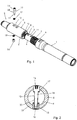
- Fig. 1 shows in an isometric representation two drill string members 1, 2 of a drill string for earth drilling.
- the two drill string members 1, 2 are shown in a position in which they can be connected to one another.
- the drill string member 1 has a plug element 3 arranged at the end in the form of a plug 4.
- the drill string member 2 has a plug element 5 arranged at the end in the form of a bush 6.
- Plug 4 and socket 6 are designed to form a plug connection.
- the outer circumference or the outer contour of the plug 4 is at least partially adapted to the inner contour of the socket 6.
- the outer contour of the plug 4 can essentially correspond to the inner contour of the socket 6.
- a profile is formed in the circumferential direction on the connector 4, which profile has contact surfaces which have a maximum deviation of 45 ° from a radial direction.
- the socket 6 has a profile 8 cooperating with the profile 7 of the plug 4 in the circumferential direction, which profile also has contact surfaces which have a maximum deviation of 45 ° from a radial direction.
- the profiles 7, 8 are designed as splined shaft profiles, which are at least partially formed unchanged in the longitudinal direction of the drill string members.
- a stop 9 which is shown closed in the exemplary embodiment, but can also be interrupted, is formed on the drill string member 1 for the drill string member 2.
- the drill string member 2 can with its bush 6 on the edge with the circumferential Edge 10, which can also be interrupted, rest against the stop 9 in order to transmit compressive forces in the longitudinal direction of the drill string members 1, 2.
- Two through holes 11 are formed on the plug 4 and are at a defined distance from the stop 9.
- Two through holes 12 are formed on the bush 6 of the drill string member 2, each of which is at a defined distance from the edge 10.
- the through holes 11, 12 are each arranged centrally parallel to one another.
- the through holes 11 on the plug 4 are aligned with the through holes 12 on the socket 6, since the distance from the stop 9 or the edge 10 is selected accordingly.
- the through holes 11, 12 form a through hole which extends through the plug 4 and socket 6 and which has a different cross section over its extension.
- a removal lock 13 can be inserted through the aligned through holes 11, 12, which prevents the plug 4 from being pulled from the socket 6 or the socket 6 from the plug 4. Tensile forces can be transmitted between the two drill string members 1, 2 through the pull-off lock 13.
- the pull-off lock 13 has a head 14 and an end 15 spaced from the head. A thread is formed at the end 15 of the pull-off lock 13. The length of the pull-off lock 13 with the head 14 and the end 15 is selected such that the end 15 is exposed at the end when the pull-off lock 13 is inserted and protrudes from the plug 4. The end 15 of the pull-off lock 13 can be screwed in the inserted position.
- a counterpart 16 is provided for screwing the pull-off lock 13 from the outside, which has an internal thread that is matched to the external thread of the end 15 of the pull-off lock 13.
- the head 14 of the anti-peeling device 13 can be arranged in a receptacle of the socket 6 in such a way that the head 14 of the anti-pull device 13 rests at least partially on the circumference of a contour arranged in the socket 6.
- the head 14 of the anti-pull device 13 is countersunk in the receptacle in the socket 6.
- the counterpart 16 is sunk in a receptacle arranged in the socket 6. On the circumferential side, the counterpart 16 rests against the outer contour of the receptacle in the socket 6.
- a securing element 17 in the form of a wedge lock washer is arranged between the head 14 and the receptacle in the socket 6, which element surrounds a shaft 18 of the pull-off lock 13 and rests on the head 14.
- the securing element 17 can loosen the screw connection between the pull-off lock 13 and the counterpart 16 and / or the pull-off lock 13 and the Prevent plug.
- a further securing element 19, which surrounds the shaft 18 in the region of the end 15, is arranged between the counterpart 16 and the receptacle in the socket 6. A loosening of the screw connection between the counterpart 16 and the pull-off lock 13 can be prevented by means of the securing element 19.
- the through holes 11 in the plug 4 are designed so that the cross section of the through holes 11 changes in the extension through the plug 4.
- the through holes 11 are designed with a larger cross section, which is reduced in the center of the plug 4.
- the enlarged cross-section of the through-holes 11 at the edge forms an at least partial receptacle of the head 14 of the peel-off lock 13 or the counterpart 16.
- the head 14 of the peel-off lock 13 therefore not only rests on the circumferential side in the area of the socket 6, but also in a circumferential area of the through-hole 11.
- the counterpart 16 which not only rests on the circumferential side in a section of the through hole 12 of the bush 6, but also in an edge region of the through hole 11.
- the pull-off lock 13 can be inserted through the aligned through holes 12 and 11 with the locking element 17 pushed on and first screwed to a thread 20 of the plug 4. The end 15 of the pull-off lock 13 is then exposed and protrudes from the plug 4. The securing element 19 can be pushed on and the counterpart 16 can be screwed onto the end 15 of the pull-off safeguard 13.
- the head of the anti-peeling device 13 is arranged partly in the plug 4 and partly in the socket 6, the enlarged bore being adapted to the head diameter in such a way that the head of the anti-peeling device 13 can act like a shear pin that allows the occurring Tensile forces (longitudinal forces) can be transmitted between plug 4 and socket 6, for example when the pipe is drawn in.
- the counterpart 16 is also arranged partly in the plug 4 and partly in the socket 6 and is configured similarly to the head for the transmission of longitudinal forces, it also being possible that only the head or only the counterpart or neither of the two is designed to transmit the longitudinal forces.
Landscapes
- Engineering & Computer Science (AREA)
- Life Sciences & Earth Sciences (AREA)
- Geology (AREA)
- Mining & Mineral Resources (AREA)
- Mechanical Engineering (AREA)
- Physics & Mathematics (AREA)
- Environmental & Geological Engineering (AREA)
- Fluid Mechanics (AREA)
- General Life Sciences & Earth Sciences (AREA)
- Geochemistry & Mineralogy (AREA)
- Earth Drilling (AREA)
Abstract
Description
- Die Erfindung betrifft ein System und ein Verfahren zum Verbinden zweier Bohrstrangglieder eines Bohrstrangs zum Erdbohren sowie eine Verwendung einer Abziehsicherung beim Verbinden zweier Bohrstrangglieder eines Bohrstrangs zum Erdbohren.
- Beim gestängebasierten Bohren im Erdreich, insbesondere zur Herstellung von sogenannten Horizontalbohrungen, die im Wesentlichen parallel oder in einem relativ geringen Neigungswinkel zur Erdoberfläche verlaufen können, wird ein Bohrkopf mittels eines Bohrgestänges, der sogenannte Bohrstrang, von einer an der Erdoberfläche oder in einer Baugrube angeordneten Antriebsvorrichtung vorgetrieben. Die dabei eingesetzten Bohrgestänge bestehen üblicherweise aus einzelnen, miteinander verbundenen Gestängeschüssen, die - dem Bohrverlauf entsprechend - nach und nach an das hintere Ende des bereits verbohrten Bohrgestänges angesetzt und mit diesem verbunden werden.
- Zur Verbindung der Gestängeschüsse bzw. Glieder des Bohrstranges miteinander sind unterschiedliche Ausgestaltungen bekannt. So können die Gestängeschüsse mittels einer Gewindeverbindung und/oder einer Steckverbindung verbunden werden.
- Aus
DE 10 2011 010 958 A1 ist es bekannt, zur Verbindung von zwei Gestängeschüssen eines Bohrgestänges eine Möglichkeit anzugeben, die die Vorteile der aus dem Stand der Technik bekannten Gewindeverbindungen und der Axialsteckverbindungen miteinander kombiniert. Dabei wird eine Steckverbindung beschrieben, die - ähnlich wie eine Gewindeverbindung - auf spiralförmige auf einem im Querschnitt kreisförmigen Gewindestecker bzw. in einer entsprechenden Gewindebuchse verlaufenden Vorsprüngen/Nuten beruht, wobei die Vorsprünge/Nuten so ausgelegt sind, dass die für eine Gewindeverbindung charakteristische Selbsthemmung nicht auftritt. - Ausgehend von diesem Stand der Technik lag der Erfindung die Aufgabe zugrunde, eine verbesserte Möglichkeit zum Verbinden zweier Bohrstrangglieder eines Bohrstrangs zum Erdbohren anzugeben, welche insbesondere eine einfachere Ausgestaltung und/oder ein sicheres und/oder einfaches Verbinden ermöglicht.
- Diese Aufgabe wird durch den Gegenstand der unabhängigen Patentansprüche gelöst. Vorteilhafte Ausführungsformen sind Gegenstand der jeweiligen abhängigen Patentansprüche und/oder ergeben sich aus der nachfolgenden Beschreibung der Erfindung.
- Der Erfindung liegt der Gedanke zugrunde, eine Möglichkeit zum Verbinden zweier Bohrstrangglieder anzugeben, welche sowohl eine Steckverbindung als auch eine Schraubverbindung miteinander vereint. Die beiden Bohrstrangglieder können ineinander gesteckt werden und es wird eine Abziehsicherung verwendet, die endseitig exponiert ist und verschraubt werden kann.
- Es wurde erfindungsgemäß erkannt, dass in Abkehr zur zuvor herrschenden Meinung, welche ein Verschrauben von Bohrstranggliedern bzw. ein Gewinde allgemein als nachteilig angesehen hat, eine verschraubbare Abziehsicherung mit zwei ineinander gesteckten Bohrstranggliedern zu verwenden, wobei das Gewinde der Abziehsicherung auch nach außen geführt werden kann, um auf dieses von außen zuzugreifen. Trotz der im Erdreich vorliegenden harschen Bedingungen und den mechanischen Belastungen und/oder Korrosion, welche zu einer großen Beanspruchung einer Gewindeverbindung führen können, wurde erfindungsgemäß erkannt, dass eine Abziehsicherung, mit einem nach außen exponierten Gewinde, welches mit einem Gegenstück von außen verschraubt werden kann, vorteilhaft sein kann. Das exponierte Ende der Abziehsicherung ermöglicht zudem, dass auf das Ende zum Lösen der Abziehsicherung zugegriffen werden kann.
- Die Erfindung schafft ein System zum Verbinden zweier Bohrstrangglieder eines Bohrstrangs zum Erdbohren, wobei ein Bohrstrangglied ein endseitig angeordnetes Steckelement in Form eines Steckers und das andere Bohrstrangglied ein endseitig angeordnetes Steckelement in Form einer Buchse aufweist. Stecker und Buchse sind zur Ausbildung einer Steckverbindung derart ausgestaltet, dass die beiden Bohrstrangglieder miteinander fluchtende Durchgangslöcher aufweisen, durch die eine Abziehsicherung einführbar ist. Die Abziehsicherung weist einen Kopf und ein vom Kopf beabstandetes Ende auf, wobei am Ende der Abziehsicherung ein Gewinde ausgebildet ist. Kopf und Ende der Abziehsicherung sind so voneinander beabstandet, dass das Ende der Abziehsicherung bei in die Durchgangslöcher eingeführter Abziehsicherung endseitig exponiert ist.
- Der Begriff "Bohrstrang" umfasst im Sinne der Beschreibung einen ein Erdbohrwerkzeug und ein Gestänge aufweisenden Strang, der zum Einbringen einer Erdbohrung durch das Erdreich mittels einer Erdbohrvorrichtung bzw. einer Antriebsvorrichtung bewegt werden kann.
- Der Begriff "Gestänge" umfasst im Sinne der Beschreibung nicht nur ausschließlich starre, einzelne miteinander unmittelbar oder mittelbar verbundene Gestängeschüsse, aufweisende Gestänge, sondern insbesondere sämtliche Kraftübertragungselemente, die bei einer Erdbohrvorrichtung eingesetzt werden können.
- Der Begriff "Gestängeschuss" im Sinne der Beschreibung umfasst ein sich entlang einer Längsachse erstreckendes Element, welches Teil des Gestänges bzw. eines Bohrstrangs zum Erdbohren ist. Der Gestängeschuss kann als vorderseitig im Bohrstrang angeordnetes Element mit zugeordneter Funktion (Sendergehäuse o. ä.) ausgebildet sein oder als ein (lediglich mechanisch) den Bohrstrang als Gestängeschuss verlängerndes Element ausgebildet sein. Der Gestängeschuss kann mechanische Kanäle, beispielsweise für Bohrfluid, elektrische Leitungen, elektrische Elemente und/oder elektronische Elemente umfassen.
- Der Begriff "Erdbohrwerkzeug" umfasst einen am vorderseitigen Ende des Bohrstrangs angeordneten Bohrkopf, bei dem bewegliche Teile vorgesehen sein können. Es kann aber auch vorgesehen sein, dass das Erdbohrwerkzeug eine unbewegliche bzw. starre oder weitestgehend unbewegliche bzw. starre Außenkontur aufweist.
- Der Begriff "Erdbohrvorrichtung" umfass im Sinne der Beschreibung jedwede Vorrichtung, die insbesondere einen Gestängeschüsse aufweisenden Bohrstrang in einem bestehenden oder zu erstellenden Kanal im Erdreich bewegen kann, um eine Bohrung, insbesondere eine Horizontalbohrung, zu erstellen oder aufzuweiten, oder um Leitungen oder andere lange Körper in das Erdreich einzuziehen. Eine Erdbohrvorrichtung kann dabei eine einen Bohrstrang ziehend und/oder drückend antreibende Antriebsvorrichtung umfassen. Es kann zusätzlich oder alternativ vorgesehen sein, dass die Antriebsvorrichtung den Bohrstrang rotatorisch antreibt.
- Der Begriff "Horizontalbohrung" (horizontal drilling) im Sinne der Beschreibung umfasst insbesondere jede Art von bestehenden oder zu erstellenden, vorzugsweise horizontalen, Kanälen in einem Körper, insbesondere Erdkanäle einschließlich Erdbohrungen, Felsbohrungen oder Erdleitungen sowie unterirdische oder oberirdische Rohrleitungen und Wasserkanäle, die sich durch Einsatz einer entsprechenden Erdbohrvorrichtung herstellen oder einziehen lassen.
- Der Begriff "Bohrstrangglied" bezeichnet einen Abschnitt des Bohrstrangs, der lösbar mit anderen Abschnitten des Bohrstrangs verbunden werden kann. Insbesondere kann ein Bohrstrangglied ein Gestängeschuss sein. Es ist auch möglich, dass ein Bohrstrangglied ein Verbindungselement für zwei Gestängeschüsse ist, die mittelbar über das Verbindungselement miteinander verbunden sind.
- Die Begriffe "Stecker" und "Buchse" umfassen im Sinne der Beschreibung eine Ausgestaltung als ein Element eines Paares von mechanischen Kupplungselementen, von denen das eine ("Stecker") zumindest teilweise in das andere ("Buchse") eingeführt werden kann, um die Verbindung auszubilden. Zur Übertragung von Rotationskräften können Stecker und/oder Buchse umfangsseitig Anschlag- bzw. Anlageflächen aufweisen, die mit Anschlag- bzw. Anlageflächen am anderen Element in Anlage sind und auf diese wechselseitig bei Schub bzw. Druck einwirken können.
- Vorteilhaft weist ein Bohrstrangmitglied an einem Ende ein Steckelement in Form eines Steckers und am anderen Ende ein Steckelement in Form einer Buchse auf. Es kann aber auch vorgesehen sein, dass das Bohrstrangglied endseitig Steckelemente gleicher Form aufweist, so dass das Bohrstrangglied an beiden Enden ein Steckelement in Form eines Steckers oder an beiden Enden ein Steckelement in Form einer Buchse aufweist.
- Im Sinne der Beschreibung ist ein "Durchgangsloch" ein durchgehendes Loch, das sich von einem Sackloch unterscheidet. Das Durchgangsloch muss nicht zwingend über die gesamte Länge den gleichen Durchmesser oder die gleiche Kontur aufweisen. Die das Durchgangsloch umgebende Kontur kann ringförmig, elipsenförmig, unrund, polygonförmig oder eine Mischform der zuvor genannten Formen aufweisen. Sofern in der Beschreibung der Begriff "fluchtend" für die Durchgangslöcher gewählt ist, so ist hierunter zu verstehen, dass das im Stecker ausgebildete Durchgangsloch zumindest teilweise mit dem Durchgangsloch in der Buchse überlappt. In einer besonders bevorzugten Ausführungsform sind die Durchgangslöcher bei aufgesteckten Bohrstranggliedern im Wesentlichen koaxial zueinander; geringe Abweichungen, insbesondere herstellungsbedingte Toleranzen, sind möglich. Es ist sinnvoll, dass die Durchgangslöcher bzw. das Durchgangsloch in der Buchse eine größere Querschnittsfläche bezogen auf die Längsachse des Durchgangslochs aufweist als die Querschnittsfläche zumindest in einem Abschnitt des Durchgangslochs in dem Stecker. Hierdurch kann ein Randbereich des Kopfs der Abziehsicherung auf einem Rand im Durchgangsloch, insbesondere im Abschnitt des Steckers, aufliegen, wenn die Abziehsicherung durch die fluchtenden Durchgangslöcher gesteckt ist. Das Durchgangsloch in der Buchse und dem Stecker ist bevorzugt im Wesentlichen quer zur Längsachse des Bohrstrangglieds ausgerichtet, wobei ein Winkel im Winkelbereich zwischen 70° und 110° bevorzugt ist, insbesondere bevorzugt ist ein Winkel nahe 90°, ganz besonders bevorzugt ist der Winkel 90°.
- Zahlenangaben im Sinne der Beschreibung sind Angaben, die mit einer Toleranz von +/- 10% behaftet sein können, so dass die Zahlenangabe nicht nur den einen Wert, sondern einen Wertebereich beschreibt, um insbesondere Toleranzbereiche, die herstellungsbedingt sein können, Rechnung zu tragen.
- Im Sinne der Beschreibung umfasst der Begriff "Abziehsicherung" ein langgestrecktes bzw. stabförmiges Element, welches durch die fluchtenden Durchgangslöcher in Stecker und Buchse gesteckt werden kann. Die Abziehsicherung weist einen Kopf auf, der insbesondere gegenüber einem Schaftabschnitt eine vergrößerte Querschnittsfläche quer zur Längsachse der Abziehsicherung aufweist. Der dem Ende zugewandte Bereich des Kopfes mit seiner gegenüber dem Ende und einem Schaftabschnitt vergrößerten Querschnittsfläche kann eine randseitige Auflagefläche aufweisen, die insbesondere auf einer nach außen (im Wesentlichen radial) gerichteten Außenfläche des Steckers aufliegen kann, wobei diese Außenfläche des Steckers innerhalb einer Aufnahme des Steckers vorliegen kann. Das vom Kopf beabstandete Ende weist ein Gewinde auf. Das Ende ist bei eingeführter Abziehsicherung endseitig exponiert. Auf das Ende und/oder Gewinde kann von außen zugegriffen werden.
- Der Stecker kann mit einem Randbereich im gesteckten Zustand der Abziehsicherung eine Auflage für den Kopf der Abziehsicherung bilden. Der Stecker kann eine Aufnahme für den Kopf aufweisen, so dass der Kopf der Abziehsicherung zumindest teilweise in dem Stecker versenkt werden kann.
- Es wird eine verbesserte Übertragung der Kräfte über die Bohrstrangglieder des Systems ermöglicht, wobei Druckkräfte über einen Anschlag der Steckverbindung zwischen Stecker und Buchse übertragen werden können. Rotationskräfte können über ein innerhalb der Steckverbindung zwischen Stecker und Buchse ausgebildetes Profil übertragen werden. Zugkräfte werden über die Abziehsicherung übertragen. Der Anschlag zum Übertragen der Druckkräfte kann mittels eines Randes der Buchse und/oder des Steckers, die im zusammengesteckten Zustand zumindest teilweise in Anlage zueinander sind, gebildet werden.
- Das zum Sichern der Abziehsicherung verwendete Gewinde muss nicht in Eingriff mit dem Bohrstrangglied selbst gelangen, sondern ein von außen zugängliches weiteres Element kann verwendet werden, welches unabhängig von den Bohrstranggliedern erneuert werden kann. Sollte das Gewinde oder die Abziehsicherung selbst erneuert werden müssen, so ist eine Überarbeitung oder Wartung des Bohrstrangglieds selbst nicht notwendig.
- Es kann aber auch in einer besonders bevorzugten Ausführungsform vorgesehen sein, dass im Steckelement in Form eines Steckers endseitig am Durchgangsloch ein Gewinde vorgesehen ist, das zum Zusammenwirken mit einem Gewinde der Abziehsicherung ausgestaltet ist. Der Begriff "Zusammenwirken" umfasst dabei im Sinne der Beschreibung eine derartige Ausgestaltung, dass die Abziehsicherung zumindest abschnittsweise ein Außengewinde aufweist, das mit dem endseitig am Durchgangsloch des Steckers ausgebildeten Innengewinde zusammenwirken kann. Über eine Schraubverbindung zwischen der Abziehsicherung und dem im Durchgangsloch des Steckers endseitig vorliegenden Gewinde, welches insbesondere an dem in Steckrichtung hinteren Ende des Durchgangslochs des Steckers angeordnet ist, kann eine Schraubverbindung ausgebildet werden, welche eine, insbesondere erste, Sicherung gegen ein unbeabsichtigtes Lösen der Abziehsicherung bilden kann. Insbesondere kann diese Sicherung ein zusätzliches Sicherungselement umfassen, welches in Form einer (Keil-)sicherungsscheibe, eines Federrings, einer Fächerscheibe oder ähnlichem, ausgebildet sein kann. Das Sicherungselement kann an dem Kopf der Abziehsicherung anliegen. Hierzu kann auf die Abziehsicherung zunächst ein Sicherungselement aufgeschoben werden. Dann kann die Abziehsicherung in die fluchtenden Durchgangslöcher von Buchse und Stecker eingesteckt und mit dem zumindest endseitig am Durchgangsloch des Steckers ausgebildeten Gewinde eingeschraubt und insbesondere festgezogen werden. Das am Kopf der Abziehsicherung vorliegende Sicherungselement kann ein Lösen der Abziehsicherung weitestgehend verhindern. Es kann, wenn das Sicherungselement als Keilsicherungsscheibe ausgestaltet ist, eine Sicherungswirkung dadurch erreicht werden, dass unterschiedliche Winkel(-verhältnisse) zwischen der Keilsicherungsscheibe und der Gewindesteigung vorliegen. Insbesondere kann an der Keilsicherungsscheibe ein Winkel α vorliegen, der größer ist als die Gewindesteigung β des Gewindes. Sofern in der Beschreibung beschrieben wird, dass am Durchgangsloch des Steckers ein Gewinde "endseitig" vorgesehen ist, so schließt dies nicht aus, dass das Gewinde sich durch das gesamte Durchgangsloch des Steckers erstreckt. Allerdings bietet eine lediglich endseitige Anordnung bzw. Ausbildung eines Gewindes am Durchgangsloch bei ansonsten gewindefreiem Durchgangsloch des Steckers den Vorteil, dass sich das Gewinde in Form eines Innengewindes am Durchgangsloch lediglich über einen kurzen Bereich erstreckt, was die Herstellung vereinfacht.
- Das Ende der Abziehsicherung, welches vom Kopf der Abziehsicherung beabstandet ist, ist mittels des in der Buchse ausgebildeten Durchgangslochs exponiert und kann ebenfalls mit einem Gewinde versehen sein. Dieses Gewinde kann gleich ausgestaltet zu dem Gewinde sein, welches mit dem Innengewinde des Durchgangslochs des Steckers zusammenwirkt. Hierdurch kann eine einfache Ausgestaltung erzielt werden. Es ist jedoch auch möglich, dass ein anderes Gewinde zusätzlich zu dem Außengewinde vorliegt, welches mit dem endseitig am Durchgangsloch des Steckers ausgebildeten Innengewinde zusammenwirkt. Insofern kann die Abziehsicherung an ihrem Ende zwei unterschiedliche Gewinde aufweisen. Im Nachfolgenden wird beschrieben, dass das exponierte Gewinde mit einem Innengewinde eines Gegenstücks zusammenwirken kann, um insbesondere eine erste (Stecker weist kein mit der Abziehsicherung zusammenwirkendes Innengewinde auf) oder eine zweite Sicherung (Stecker weist ein mit der Abziehsicherung zusammenwirkendes Innengewinde auf) gegen Verlieren der Abziehsicherung zu bilden.
- In einer bevorzugten Ausführungsform ist der Kopf der Abziehsicherung zum Zusammenwirken mit einem Werkzeug, insbesondere einem "von oben" auf die Abziehsicherung einwirkenden Werkzeug, ausgestaltet. Zum einen kann hierdurch ermöglicht werden, dass mittels einer Vorrichtung auf die Abziehsicherung eingewirkt werden kann, um die Handhabung zu verbessern und/oder einen direkten Kontakt mit den Händen eines Anwenders bzw. Benutzers zu vermeiden. Zum anderen können insbesondere Werkzeuge bevorzugt sein, die in einer Richtung, die im Wesentlichen der Längsrichtung der Abziehsicherung entspricht, auf die dem Ende der Abziehsicherung beabstandeten Seite der Abziehsicherung einwirken. Insbesondere sind Werkzeuge bevorzugt, die auf eine Stirnfläche des Kopfs einwirken, die im Wesentlichen in Längsrichtung der Abziehsicherung exponiert ist. Einwirkungen eines Werkzeugs von der Seite von außen, beispielsweise in Form eines Steckschlüssels oder eines Schraubenschlüssels sind möglich, aber nicht bevorzugt, da diese umfangsseitig von außen angreifen und hierzu Platz benötigt wird. Ein lediglich in eine Ausnehmung des Kopfes, die in Längsrichtung der Abziehsicherung ausgebildet ist, eingreifendes Werkzeug ermöglicht, dass das Werkzeug in diese Ausnehmung eingreifen kann und erlaubt, dass die Abziehsicherung mit ihrem Kopf insbesondere zumindest teilweise umfangsseitig an einem oder beiden Bohrgestängegliedern anliegen kann. Eine an der Abziehsicherung ausgebildete Aufnahme zum Zusammenwirken mit einem Inbusschlüssel, Innensechskant, Torx oder XZN (Innenvielzahnprofile) ist bevorzugt.
- In einer bevorzugten Ausführungsform ist der Kopf der Abziehsicherung in einer Aufnahme an der Buchse zumindest teilweise versenkbar. Hierdurch wird erreicht, dass die Querschnittsfläche der Bohrstrangglieder nicht wesentlich erhöht wird bzw. auch gegenüber einem Bohrstrangglied ohne Abziehsicherung keine Veränderung der Querschnittsfläche auftritt. Zudem liefert eine Aufnahme in der Buchse die Möglichkeit, dass die Abziehsicherung zumindest mit ihrem Kopf umfangsseitig an der Buchse anliegen kann, so dass nicht nur über einen Schaftabschnitt der Abziehsicherung die Zugkräfte übertragen werden können, sondern auch über den Kopf der Abziehsicherung. Die Aufnahme an der Buchse kann insbesondere mit ihrer Innenkontur der Außenkontur des Kopfes der Abziehsicherung zumindest teilweise entsprechen bzw. an diese angepasst sein. Ein Formschluss ist möglich. Der Querschnitt des Kopfes der Abziehsicherung und der Querschnitt der Aufnahme können rund ausgebildet sein, insbesondere in Form eines Kreises. Andere Formen sind möglich, beispielsweise können Kopf und/oder Aufnahme ellipsenförmig, polygonförmig, rechteckig, quadratisch oder mehreckig ausgestaltet sein oder Mischformen hiervon aufweisen. Bevorzugt kann der Stecker auch eine Aufnahme für den Kopf der Abziehsicherung aufweisen, so dass der Kopf der Abziehsicherung zumindest teilweise in die Richtung der Erstreckung des Durchgangslochs in dem Stecker versenkbar ist. Hierdurch kann die Möglichkeit geschaffen werden, dass der Kopf auch oder ausschließlich umfangsseitig an einem Rand der Aufnahme im Stecker anliegt und hierüber eine Kraftübertragung möglich ist. Ein Formschluss ist möglich. Die Aufnahme im Stecker kann entsprechend der Aufnahme in der Buchse ausgestaltet sein.
- Es ist möglich, dass auf die Abziehsicherung in Längsrichtung Sicherungselemente aufgeschoben werden, von denen insbesondere eines randseitig am Kopf der Abziehsicherung anliegen kann. Alternativ oder zusätzlich kann vorgesehen sein, dass ein Sicherungselement auf das exponierte Ende der Abziehsicherung bei eingesteckter und/oder aufgeschraubter Abziehsicherung aufgeschoben werden kann. Ein derartiges Sicherungselement wurde im Zusammenhang mit der Anlage am Kopf oben beschrieben. Das auf das exponierte Ende der Abziehsicherung aufzuschiebende Sicherungselement kann ebenso wie das oben mit Bezug auf die Anlage am Kopf der Abziehsicherung beschriebene Sicherungselement ausgestaltet sein.
- In einer bevorzugten Ausführungsform ist ein mit dem Gewinde der Abziehsicherung zusammenwirkendes Gegenstück vorhanden. Das Gegenstück kann ausgetauscht werden, ohne dass es eines Austausches eines oder beider der Bohrstrangglieder bedarf.
- Im Zusammenhang mit dem Gegenstück kann ein auf das exponierte Ende aufgeschobenes Sicherungselement eine zusätzliche Sicherung darstellen, die ein Lösen der Abziehsicherung zusätzlich zu der Sicherung mittels des Gegenstücks bietet. Beispielsweise kann auf das am Ende der Abziehsicherung ausgestaltete Gewinde ein Gegenstück aufgeschraubt werden und kann im Zusammenspiel mit der Schraubverbindung zwischen Abziehsicherung und endseitigem Gewinde am Stecker wie eine Kontermutter wirken. Hierdurch kann eine Sicherung gegen das Verlieren der Abziehsicherung gebildet werden. Das auf das exponierte Ende der Abziehsicherung aufgeschobene Sicherungselement, das vor dem Gegenstück auf die Abziehsicherung aufgeschoben werden kann, kann eine dritte Sicherung sein.
- In einer bevorzugten Ausführungsform ist das Gegenstück zum Zusammenwirken mit einem Werkzeug ausgestaltet. Hierdurch kann die Möglichkeit geschaffen werden, dass mit einer Vorrichtung auf das Gegenstück eingewirkt werden kann. Bevorzugt kann das Werkzeug auf das Gegenstück - ebenso wie bei dem Kopf der Abziehsicherung - "von oben" angreifen. Es kann insbesondere vorgesehen sein, dass das Werkzeug nicht an der Seite des Gegenstücks angreift. Bevorzugt ist eine nach oben ausgerichtete (im Wesentlichen in Längsrichtung ausgerichtete vom Ende beabstandete) Ausnehmung vorgesehen, in die das Werkzeug eingreifen kann. Hierdurch kann die Möglichkeit geschaffen werden, dass das Gegenstück zumindest teilweise umfangsseitig an einem oder beiden der Bohrgestängeglieder anliegt. Insbesondere kann das Gegenstück umfangsseitig zumindest teilweise an der Buchse anliegen. Insbesondere sind Werkzeuge bevorzugt, die ausschließlich auf die Stirnseite des Gegenstücks einwirken, die im Wesentlichen in Längsrichtung bestandet zum mit dem am Ende der Abziehsicherung ausgestalteten Gewinde zusammenwirkenden Gewinde vorliegt. Einwirkungen eines Werkzeugs von der Seite, beispielsweise in Form eines Steckschlüssels oder eines Schraubenschlüssels sind möglich, aber nicht bevorzugt, da diese von der Seite angreifen und hierzu Platz benötigt wird. Ein in eine Ausnehmung des Gegenstücks, die in Längsrichtung ausgebildet ist, eingreifendes Werkzeug ermöglicht, dass das Werkzeug in diese Ausnehmung eingreifen kann und erlaubt, dass das Gegenstück insbesondere zumindest teilweise umfangsseitig an einem oder beiden Bohrgestängegliedern anliegen kann. Eine am Gegenstück ausgebildete Aufnahme zum Zusammenwirken mit einem Inbusschlüssel, Innensechskant, Torx oder XZN (Innenvielzahnprofile) ist bevorzugt.
- In einer bevorzugten Ausführungsform ist das Gegenstück in einer Aufnahme an der Buchse zumindest teilweise versenkbar. Hierdurch kann erreicht werden, dass keine wesentliche Erhöhung der Querschnittsfläche des Bohrstranggliedes erreicht wird, bzw. es zu keiner Erhöhung der Querschnittsfläche des Bohrstranggliedes kommt. Es ist auch ein teilweises Versenken des Gegenstücks in einer im Stecker ausgebildeten Aufnahme möglich.
- Eine Aufnahme für den Kopf der Abziehsicherung oder eine Aufnahme für das Gegenstück wird mittels einer an die randseitige Außenabmessung des Kopfs bzw. des Gegenstücks angepassten Abmessung des Durchgangslochs erreicht. Eine Aufnahme kann somit mittels eines an den Querschnitt des Kopfes bzw. des Gegenstücks angepassten Querschnitts des Durchgangslochs gebildet werden. Der Rand der Aufnahme kann im Wesentlichen dem Rand des Kopfes bzw. des Gegenstücks entsprechen, oder größer als dieser ausgebildet sein. Die Aufnahme kann mittels einer Querschnittsverringerung des Durchgangslochs beendet sein.
- In einer bevorzugten Ausführungsform ist an der Abziehsicherung zwischen Kopf und Ende ein Schaftabschnitt vorgesehen, der gewindelos ausgebildet ist und/oder dessen Umfang größer ist als der Umfang des Endes. Hierdurch kann erreicht werden, dass eine Stabilität der Anlage der Abziehsicherung an den beiden Bohrstranggliedern verbessert bzw. erhöht wird. Durch die Nichtbearbeitung und/oder die Wahl der Abmessung des Schaftabschnitts kann die Stabilität verbessert werden. Dadurch dass der Umfang am Ende gegenüber dem Umfang am Schaftabschnitt verringert ist, wird eine Materialschwächung im Bereich des Steckers verringert bzw. ausgeschlossen. Etwaige Zugbelastungen auf die Bohrstrangglieder, die zumindest teilweise über die Abziehsicherung übertragen werden, können durch den Schaftabschnitt, der verstärkt ausgebildet ist, übertragen werden.
- In einer bevorzugten Ausführungsform sind die Durchgangslöcher der Buchse und/oder des Steckers gewindelos ausgestaltet. Hierdurch ist eine besonders einfache Ausgestaltung der Bohrstrangglieder möglich. Insbesondere muss kein Gewinde im Durchgangsloch ausgebildet werden, mit dem die Abziehsicherung zusammenwirken kann. Der Arbeitsschritt des Erstellens oder Ausbildens eines Gewindes am Bohrstrangglied entfällt. Durch die gewindelose Ausgestaltung der Durchgangslöcher ist die Wartung der Bohrstrangglieder hiervon unberührt.
- In einer besonders bevorzugten Ausführungsform ist, wie oben beschrieben, endseitig am Durchgangsloch des Steckers ein Gewinde ausgebildet, welches insbesondere als Innengewinde vorliegt und das zum Zusammenwirken mit einem Gewinde der Abziehsicherung ausgestaltet ist. Hierdurch kann eine Sicherung gegen das Verlieren der Abziehsicherung ermöglicht werden, welche effektiv ist.
- In einer besonders bevorzugten Ausführungsform sind die Durchgangslöcher im Wesentlichen quer zur Längsachse des Bohrstrangs ausgebildet und/oder mittig im Querschnitt ausgebildet. Hierdurch wird eine Stabilität des Eingriffs und der Verbindung bei Zugbelastung ermöglicht. Die Belastung der Durchgangslöcher, insbesondere für den Stecker, erfolgt in dem Bereich, in dem das meiste Material vorhanden ist. Ferner kann eine Zugbelastung über die gesamte Breite übertragen werden und eine Verwinklung wird nahezu ausgeschlossen.
- In einer bevorzugten Ausführungsform sind in Längsrichtung der Bohrstrangglieder beabstandet mehrere Durchgangslöcher in zumindest einem der Steckelemente ausgebildet. Hierdurch können mehrere Abziehsicherungen beim Verbinden der Bohrstrangglieder eingeführt und verwendet werden, die eine Zugkraft übertragen können.
- In einer bevorzugten Ausführungsform weisen Stecker und Buchse umfangsseitig jeweils ein Profil auf, welche beim Ausbilden der Steckverbindung zur Übertragung von Rotationskräften im Uhrzeigersinn und/oder gegen den Uhrzeigersinn um die Längsachse zusammenwirken können.
- Das Profil erlaubt die Übertragung von Rotationskräften zwischen den Bohrstrangsgliedern bei ausgebildeter Steckverbindung. Der Stecker weist am Außenumfang Anlageflächen auf, die mit Anlageflächen in der Buchse in Eingriff gebracht werden können, wobei sich die Anlageflächen zumindest teilweise in radialer Richtung erstrecken können, um die Rotationskräfte übertragen zu können. In radialer Richtung umfasst im Sinne der Beschreibung Anlageflächen, die einen Winkel von 0° bis 45° zur radialen Richtung aufweisen können. Das Profil kann zumindest teilweise in Steckrichtung unverändert sein. Durch das Profil ist es möglich, Rotationskräfte vom einen Bohrstrangglied auf das andere Bohrstrangglied zu übertragen. Es kann ein Profil vorgesehen sein, das zumindest teilweise in Längsrichtung unverändert ist. Es kann aber auch alternativ oder zusätzlich vorgesehen sein, dass sich das Profil in Längsrichtung betrachtet verändert, beispielsweise dadurch, dass eine Steckverbindung gewählt ist, bei der spiralförmiger auf einem im Querschnitt kreisförmigen Gewindestecker bzw. in einer entsprechenden Gewindebuchse verlaufende Vorsprünge/Nuten aufweist. Besonders bevorzugt sind Profile, die abschnittsweise in Längsrichtung unverändert sind. Hierdurch kann eine vereinfachte Herstellung ermöglicht werden. Bevorzugt wird ein Zahnwellenprofil verwendet.
- Die Erfindung schafft auch ein Verfahren zum Verbinden zweier Bohrstrangglieder eines Bohrstrangs zum Erdbohren. Die zwei Bohrstrangglieder werden endseitig ineinander gesteckt und dabei so ausgerichtet, dass in den Bohrstranggliedern angeordnete Durchgangslöcher fluchten, wobei durch die Durchgangslöcher eine Abziehsicherung gesteckt wird, deren exponiertes Ende mit einem Gegenstück verschraubt werden kann.
- Es wird ein Verfahren geschaffen, mit dem insbesondere Verletzungsgefahren für den Anwender, der die Bohrstrangglieder miteinander verbindet, reduziert sind, und dennoch eine sichere und belastbare Verbindung, die einfach vorgenommen werden kann und/oder einfach aufgebaut ist, möglich ist.
- Die Erfindung schafft auch eine Verwendung einer Abziehsicherung beim Verbinden zweier Bohrstrangglieder eines Bohrstrangs zum Erdbohren. Die zwei Bohrstrangglieder werden endseitig ineinander gesteckt und dabei so ausgerichtet, dass in den Bohrstranggliedern angeordnete Durchgangslöcher fluchten. Die Abziehsicherung wird durch die Durchgangslöcher gesteckt, wobei eine Abziehsicherung verwendet wird, deren exponiertes Ende mit einem Gegenstück verschraubbar ist.
- Die Ausführungen zu den einzelnen Aspekten der Erfindung, wie sie in Bezug auf das System, das Verfahren und die Verwendung beschrieben werden, sind als einander ergänzende Ausführungen zu verstehen. Ausführungen zu einem Aspekt gelten auch für die Ausführungen für einen der anderen Aspekte.
- Die vorstehenden Ausführungen stellen ebenso wie die nachfolgende Beschreibung beispielhafter Ausführungsformen keinen Verzicht auf bestimmte Ausführungsformen oder Merkmale dar.
- Die Erfindung wird nachfolgend anhand von in den Zeichnungen dargestellten Ausführungsbeispielen näher erläutert.
- In den Zeichnungen zeigt:
- Fig. 1
- zwei Bohrstrangglieder eines Bohrstrangs zum Erdbohren mit einer Abziehsicherung und einem Gegenstück;
- Fig. 2
- eine Schnittdarstellung der zwei in
Fig. 1 dargestellten Bohrstrangglieder mit eingeführter Abziehsicherung und montiertem Gegenstück. -
Fig. 1 zeigt in einer isometrischen Darstellung zwei Bohrstrangglieder 1, 2 eines Bohrstrangs zum Erdbohren. Die beiden Bohrstrangglieder 1, 2 sind in einer Stellung gezeigt, wie sie miteinander verbunden werden können. Das Bohrstrangglied 1 weist ein endseitig angeordnetes Steckelement 3 in Form eines Steckers 4 auf. Das Bohrstrangglied 2 weist ein endseitig angeordnetes Steckelement 5 in Form einer Buchse 6 auf. - Stecker 4 und Buchse 6 sind zur Ausbildung einer Steckverbindung ausgestaltet. Insbesondere ist der Außenumfang bzw. die Außenkontur des Steckers 4 zumindest teilweise an die Innenkontur der Buchse 6 angepasst. Die Außenkontur des Steckers 4 kann im Wesentlichen der Innenkontur der Buchse 6 entsprechen.
- Zur Übertragung von Rotationskräften zwischen den beiden Bohrstranggliedern 1 und 2 des Bohrstrangs ist am Stecker 4 ein Profil in Umfangsrichtung ausgebildet, das Anlageflächen aufweist, die gegenüber einer radialen Richtung eine maximale Abweichung von 45° aufweisen. Die Buchse 6 weist ein mit dem Profil 7 des Steckers 4 zusammenwirkendes Profil 8 in Umfangsrichtung auf, welches ebenfalls Anlageflächen aufweist, die gegenüber einer radialen Richtung eine maximale Abweichung von 45° aufweisen. Im in
Figur 1 dargestellten Ausführungsbeispiel sind die Profile 7, 8 als Zahnwellenprofile ausgestaltet, die zumindest teilweise in Längsrichtung der Bohrstrangglieder unverändert ausgebildet ist. - Am Bohrstrangglied 1 ist für das Bohrstrangglied 2 ein Anschlag 9, der im Ausführungsbespiel geschlossen dargestellt ist, aber auch unterbrochen sein kann, ausgebildet. Das Bohrstrangglied 2 kann mit seiner Buchse 6 randseitig mit dem umlaufenden Rand 10, der auch unterbrochen sein kann, am Anschlag 9 anliegen, um Druckkräfte in Längsrichtung der Bohrstrangglieder 1, 2 zu übertragen.
- Am Stecker 4 sind zwei Durchgangslöcher 11 ausgebildet, die einen definierten Abstand zum Anschlag 9 aufweisen. An der Buchse 6 des Bohrstrangglieds 2 sind zwei Durchgangslöcher 12 ausgebildet, die einen definierten Abstand jeweils zum Rand 10 aufweisen. Die Durchgangslöcher 11, 12 sind jeweils parallel zueinander mittig angeordnet.
- Im zusammengesteckten Zustand der Bohrstrangglieder 1, 2 fluchten die Durchgangslöcher 11 am Stecker 4 mit den Durchgangslöchern 12 an der Buchse 6, da der Abstand vom Anschlag 9 bzw. dem Rand 10 entsprechend gewählt ist. Die Durchgangslöcher 11, 12 bilden ein durch Stecker 4 und Buchse 6 durchgehendes Durchgangsloch, das über seine Erstreckung einen unterschiedlichen Querschnitt aufweist.
- Durch die fluchtenden Durchgangslöcher 11, 12 kann eine Abziehsicherung 13 eingeführt werden, die ein Abziehen des Steckers 4 von der Buchse 6 bzw. der Buchse 6 vom Stecker 4 verhindert. Durch die Abziehsicherung 13 können Zugkräfte zwischen den beiden Bohrstranggliedern 1, 2 übertragen werden.
- Die Abziehsicherung 13 weist einen Kopf 14 und ein vom Kopf beabstandetes Ende 15 auf. Am Ende 15 der Abziehsicherung 13 ist ein Gewinde ausgebildet. Die Länge der Abziehsicherung 13 mit dem Kopf 14 und dem Ende 15 ist derart gewählt, dass das Ende 15 bei eingeführter Abziehsicherung 13 endseitig exponiert ist und aus dem Stecker 4 herausragt. Das Ende 15 der Abziehsicherung 13 kann in der eingeführten Position verschraubt werden.
- Zum Verschrauben der Abziehsicherung 13 von außen ist ein Gegenstück 16 vorgesehen, dass ein an das Außengewinde des Endes 15 der Abziehsicherung 13 angepasstes Innengewinde aufweist.
- Der Kopf 14 der Abziehsicherung 13 ist in einer Aufnahme der Buchse 6 so anordbar, dass der Kopf 14 der Abziehsicherung 13 umfangsseitig an einer in der Buchse 6 angeordneten Kontur zumindest teilweise anliegt. Der Kopf 14 der Abziehsicherung 13 ist in der Aufnahme in der Buchse 6 versenkt. Das Gegenstück 16 ist in einer in der Buchse 6 angeordneten Aufnahme versenkt. Umfangsseitig liegt das Gegenstück 16 an der Außenkontur der Aufnahme in der Buchse 6 an. Zwischen dem Kopf 14 und der Aufnahme in der Buchse 6 ist ein Sicherungselement 17 in Form einer Keilsicherungsscheibe angeordnet, das einen Schaft 18 der Abziehsicherung 13 umgibt und am Kopf 14 anliegt. Das Sicherungselement 17 kann ein Lösen der Verschraubung zwischen Abziehsicherung 13 und Gegenstück 16 und/oder Abziehsicherung 13 und dem Stecker verhindern. Zwischen dem Gegenstück 16 und der Aufnahme in der Buchse 6 ist ein weiteres Sicherungselement 19 angeordnet, das den Schaft 18 im Bereich des Endes 15 umgibt. Mittels des Sicherungselements 19 kann ein Lösen der Verschraubung zwischen Gegenstück 16 und Abziehsicherung 13 verhindert werden.
- Im in
Fig. 1 dargestellten Ausführungsbeispiel sind die Durchgangslöcher 11 im Stecker 4 so ausgebildet, dass sich der Querschnitt der Durchgangslöcher 11 in der Erstreckung durch den Stecker 4 ändert. Endseitig am Stecker 4 sind die Durchgangslöcher 11 mit einem größeren Querschnitt ausgestaltet, der sich in der Mitte des Steckers 4 verringert. Der vergrößerte randseitige Querschnitt der Durchgangslöcher 11 bildet eine zumindest teilweise Aufnahme des Kopfes 14 der Abziehsicherung 13 bzw. des Gegenstücks 16. Der Kopf 14 der Abziehsicherung 13 liegt damit nicht nur umfangsseitig im Bereich der Buchse 6 an, sondern auch in einem umfangsseitigen Bereich des Durchgangslochs 11. Analoges gilt für das Gegenstück 16, das nicht nur umfangsseitig in einem Abschnitt des Durchgangslochs 12 der Buchse 6 anliegt, sondern auch in einem randseitigen Bereich des Durchgangslochs 11. - Endseitig ist im Durchgangsloch 11 im Stecker 4 ein Innengewinde 20 vorhanden, das mit einem Gewinde der Abziehsicherung 13 zusammenwirken kann. Die Abziehsicherung 13 kann durch die fluchtenden Durchgangslöcher 12 und 11 mit aufgeschobenem Sicherungselement 17 eingeschoben und zunächst mit einem Gewinde 20 des Steckers 4 verschraubt werden. Das Ende 15 der Abziehsicherung 13 ist dann exponiert und ragt aus dem Stecker 4 hervor. Das Sicherungselement 19 kann aufgeschoben werden und auf das Ende 15 der Abziehsicherung 13 kann das Gegenstück 16 aufgeschraubt werden.
- Der Kopf der Abziehsicherung 13 ist zum Teil im Stecker 4 und zum Teil in der Buchse 6 angeordnet, wobei die vergrößerte Bohrung an dem Kopfdurchmesser derart angepasst ist, dass der Kopf der Abziehsicherung 13 wie ein Scherstift wirken kann, der es zulässt, dass die auftretenden Zugkräfte (Längskräfte) beispielsweise beim Rohreinzug zwischen Stecker 4 und Buchse 6 übertragen werden können. Im in den Figuren dargestellten Ausführungsbeispiel ist das Gegenstück 16 ebenfalls zum Teil im Stecker 4 und zum Teil in der Buchse 6 angeordnet und ähnlich wie der Kopf zur Übertragung von Längskräften ausgestaltet, wobei es auch möglich ist, dass nur der Kopf oder nur das Gegenstück oder keines von beiden zur Übertragung der Längskräfte ausgestaltet ist.
Claims (13)
- System zum Verbinden zweier Bohrstrangglieder (1, 2) eines Bohrstrangs zum Erdbohren, wobei ein Bohrstrangglied (1) ein endseitig angeordnetes Steckelement (3) in Form eines Steckers (4) und das andere Bohrstrangglied (2) ein endseitig angeordnetes Steckelement (5) in Form einer Buchse (6) aufweist, wobei Stecker (4) und Buchse (6) zur Ausbildung einer Steckverbindung derart ausgestaltet sind, dass die beiden Bohrstrangglieder (1, 2) miteinander fluchtende Durchgangslöcher (11) aufweisen, durch die eine Abziehsicherung (13) einführbar ist, und die Abziehsicherung (13) einen Kopf (14) und ein vom Kopf beabstandetes Ende (15) aufweist, wobei am Ende (15) ein Gewinde ausgebildet ist und Kopf (14) und Ende (15) so voneinander beabstandet sind, dass das Ende (15) bei eingeführter Abziehsicherung (13) endseitig exponiert ist.
- System nach Anspruch 1, wobei der Kopf (14) der Abziehsicherung (13) zum Zusammenwirken mit einem Werkzeug, insbesondere einem Inbusschlüssel, ausgestaltet ist.
- System nach Anspruch 1, wobei der Kopf (14) der Abziehsicherung (13) in einer Aufnahme an der Buchse (5) zumindest teilweise versenkbar ist.
- System nach einem der Ansprüche 1 bis 3, wobei ein mit dem Gewinde der Abziehsicherung (13) zusammenwirkendes Gegenstück (16) vorhanden ist.
- System nach Anspruch 4, wobei das Gegenstück (16) zum Zusammenwirken mit einem Werkzeug ausgestaltet ist.
- System nach Anspruch 4 oder 5, wobei das Gegenstück (16) in einer Aufnahme an der Buchse (6) zumindest teilweise versenkbar ist.
- System nach einem der Ansprüche 1 bis 6, wobei an der Abziehsicherung (13) zwischen Kopf (14) und Ende (15) ein Schaftabschnitt vorgesehen ist, der insbesondere gewindelos ausgestaltet ist und/oder dessen Umfang größer ist als der Umfang des Endes.
- System nach einem der Ansprüche 1 bis 7, wobei die Durchgangslöcher (11, 12) gewindelos ausgestaltet sind.
- System nach einem der Ansprüche 1 bis 7, wobei endseitig am Durchgangsloch (11) des Steckers (4) ein Gewinde vorgesehen ist, das zum Zusammenwirken mit einem Gewinde der Abziehsicherung (13) ausgestaltet ist.
- System nach einem der Ansprüche 1 bis 9, wobei die Durchgangslöcher (11, 12) im Wesentlichen quer zur Längsachse des Bohrstranggliedes (1, 2) verlaufen und/oder mittig im Querschnitt ausgebildet sind.
- System nach einem der Ansprüche 1 bis 10, wobei Stecker (4) und Buchse (6) je ein Profil (7) aufweisen, welche beim Stecken zusammenwirken.
- Verfahren zum Verbinden zweier Bohrstrangglieder (1, 2) eines Bohrstrangs zum Erdbohren, wobei die zwei Bohrstrangglieder (1, 2) endseitig ineinander gesteckt werden und dabei so ausgerichtet werden, dass in den Bohrstranggliedern (1, 2) angeordnete Durchgangslöcher (11) fluchten, wobei durch die Durchgangslöcher (11) eine Abziehsicherung (13) gesteckt wird, deren exponiertes Ende mit einem Gegenstück (16) verschraubt werden kann.
- Verwendung einer Abziehsicherung (13) beim Verbinden zweier Bohrstrangglieder (1, 2) eines Bohrstrangs zum Erdbohren, wobei die zwei Bohrstrangglieder (1, 2) endseitig ineinander gesteckt werden und dabei so ausgerichtet werden, dass in den Bohrstranggliedern (1, 2) angeordnete Durchgangslöcher (11, 12) fluchten, wobei durch die Durchgangslöcher die Abziehsicherung (13) gesteckt wird, wobei eine Abziehsicherung (13) verwendet wird, deren exponiertes Ende (15) mit einem Gegenstück (16) verschraubbar ist.
Applications Claiming Priority (2)
| Application Number | Priority Date | Filing Date | Title |
|---|---|---|---|
| DE102018004951.6A DE102018004951A1 (de) | 2018-06-22 | 2018-06-22 | Verbindung zweier Bohrstrangglieder eines Bohrstrangs zum Erdbohren |
| EP19181205.6A EP3587729B1 (de) | 2018-06-22 | 2019-06-19 | Verbindung zweier bohrstrangglieder eines bohrstrangs zum erdbohren |
Related Parent Applications (1)
| Application Number | Title | Priority Date | Filing Date |
|---|---|---|---|
| EP19181205.6A Division EP3587729B1 (de) | 2018-06-22 | 2019-06-19 | Verbindung zweier bohrstrangglieder eines bohrstrangs zum erdbohren |
Publications (2)
| Publication Number | Publication Date |
|---|---|
| EP3868998A1 true EP3868998A1 (de) | 2021-08-25 |
| EP3868998B1 EP3868998B1 (de) | 2023-09-27 |
Family
ID=66998327
Family Applications (2)
| Application Number | Title | Priority Date | Filing Date |
|---|---|---|---|
| EP21167590.5A Active EP3868998B1 (de) | 2018-06-22 | 2019-06-19 | Verbindung zweier bohrstrangglieder eines bohrstrangs zum erdbohren |
| EP19181205.6A Active EP3587729B1 (de) | 2018-06-22 | 2019-06-19 | Verbindung zweier bohrstrangglieder eines bohrstrangs zum erdbohren |
Family Applications After (1)
| Application Number | Title | Priority Date | Filing Date |
|---|---|---|---|
| EP19181205.6A Active EP3587729B1 (de) | 2018-06-22 | 2019-06-19 | Verbindung zweier bohrstrangglieder eines bohrstrangs zum erdbohren |
Country Status (2)
| Country | Link |
|---|---|
| EP (2) | EP3868998B1 (de) |
| DE (1) | DE102018004951A1 (de) |
Families Citing this family (2)
| Publication number | Priority date | Publication date | Assignee | Title |
|---|---|---|---|---|
| CN116157583A (zh) | 2020-07-28 | 2023-05-23 | 维米尔制造公司 | 用于水平定向钻井系统的钻柱接头 |
| DE102020005982A1 (de) * | 2020-09-30 | 2022-03-31 | Tracto-Technik Gmbh & Co. Kg | Gestängeschuss eines Erdbohrgestänges, Antriebselement, Gestängeschusssystem und Erdbohrvorrichtung |
Citations (5)
| Publication number | Priority date | Publication date | Assignee | Title |
|---|---|---|---|---|
| DE9319852U1 (de) * | 1993-12-23 | 1995-01-26 | Begemann, Jürgen, 32457 Porta Westfalica | Steckkupplungen zum Zusammenfügen von Bohrstangen zu einem Bohrgestänge |
| DE10327732A1 (de) * | 2003-06-18 | 2005-01-05 | Klemm Bohrtechnik Zweigniederlassung Der Bauer Maschinen Gmbh | Bohrgestänge mit Positionsstift |
| DE102011010958A1 (de) | 2011-02-10 | 2012-08-16 | Tracto-Technik Gmbh & Co. Kg | Steckverbindung und Gestängeschuss für Bohrgestänge |
| US20140353045A1 (en) * | 2011-09-13 | 2014-12-04 | Atlas Copco Canada Inc. | Drill pipe with replaceable tool joints |
| US20150368989A1 (en) * | 2014-06-23 | 2015-12-24 | Arthur W. Lauder | Downhole coupling |
Family Cites Families (3)
| Publication number | Priority date | Publication date | Assignee | Title |
|---|---|---|---|---|
| GB576547A (en) * | 1944-09-12 | 1946-04-09 | Walter Raylor | Improvements in pipe or tube couplings |
| US3301581A (en) * | 1965-09-30 | 1967-01-31 | Robbins & Assoc James S | Drilling shafts |
| US20050196231A1 (en) * | 2004-03-03 | 2005-09-08 | Mckay Frederick D. | Quick-locking connector |
-
2018
- 2018-06-22 DE DE102018004951.6A patent/DE102018004951A1/de not_active Ceased
-
2019
- 2019-06-19 EP EP21167590.5A patent/EP3868998B1/de active Active
- 2019-06-19 EP EP19181205.6A patent/EP3587729B1/de active Active
Patent Citations (5)
| Publication number | Priority date | Publication date | Assignee | Title |
|---|---|---|---|---|
| DE9319852U1 (de) * | 1993-12-23 | 1995-01-26 | Begemann, Jürgen, 32457 Porta Westfalica | Steckkupplungen zum Zusammenfügen von Bohrstangen zu einem Bohrgestänge |
| DE10327732A1 (de) * | 2003-06-18 | 2005-01-05 | Klemm Bohrtechnik Zweigniederlassung Der Bauer Maschinen Gmbh | Bohrgestänge mit Positionsstift |
| DE102011010958A1 (de) | 2011-02-10 | 2012-08-16 | Tracto-Technik Gmbh & Co. Kg | Steckverbindung und Gestängeschuss für Bohrgestänge |
| US20140353045A1 (en) * | 2011-09-13 | 2014-12-04 | Atlas Copco Canada Inc. | Drill pipe with replaceable tool joints |
| US20150368989A1 (en) * | 2014-06-23 | 2015-12-24 | Arthur W. Lauder | Downhole coupling |
Also Published As
| Publication number | Publication date |
|---|---|
| EP3587729A1 (de) | 2020-01-01 |
| DE102018004951A1 (de) | 2019-12-24 |
| EP3587729B1 (de) | 2021-04-14 |
| EP3868998B1 (de) | 2023-09-27 |
Similar Documents
| Publication | Publication Date | Title |
|---|---|---|
| DE602005000908T2 (de) | Verfahren zur Verwendung einer Anti-Rotations-Einrichtung für komplementäre Verbindungsstücke | |
| DE69413011T2 (de) | Rohrverbindung mit nicht-schwalbenschwanzförmigen ineinandergreifenden keilförmigen gewindegängen | |
| DE102011107348A1 (de) | "Verbindungsvorrichtung" | |
| DE102015109278B4 (de) | Verbindungssystem, Klemmschraube, Verfahren zum Verbinden zweier Bauteile | |
| EP3482092B9 (de) | Dübelschraube | |
| DE102004020000B4 (de) | Abhängeelement | |
| DE102012025187A1 (de) | Verbindungsvorrichtung | |
| EP3449153B1 (de) | Kenterschäkel | |
| EP1117897B1 (de) | Bohrgestänge zum drehschlagbohren, insbesondere zum überlagerungsbohren | |
| EP3587729B1 (de) | Verbindung zweier bohrstrangglieder eines bohrstrangs zum erdbohren | |
| EP3006748A1 (de) | Bohrschraube | |
| DE202014103640U1 (de) | Schraubdom zum Befestigen eines Bauteils | |
| DE19803304C2 (de) | Bohrgestänge zum Drehschlagbohren, insbesondere zum Überlagerungsbohren | |
| EP1426533B1 (de) | Vorrichtung zur Befestigung von Beschlagteilen an Mehrkammerprofilen | |
| DE102009051540A1 (de) | Selbstsichernde Einstelleinrichtung, Fahrzeuglenkung und Verfahren zum Einstellen eines Spiels eines Druckstück in einer Fahrzeuglenkung | |
| DE102020112157A1 (de) | Formschlüssige Bauteilverbindung und Energieverzehrvorrichtung einer Schienenfahrzeugkupplung mit einer solchen Bauteilverbindung | |
| EP4403740B1 (de) | Gewindeverbindung | |
| DE102011111064A1 (de) | Anordnung zur, insbesondere distanzierten, Befestigung zumindest einer Dammstoffplatte an einem Gebäude | |
| DE202018003674U1 (de) | Verbindung zweier Bohrstrangglieder eines Bohrstrangs zum Erdbohren | |
| DE102020005982A1 (de) | Gestängeschuss eines Erdbohrgestänges, Antriebselement, Gestängeschusssystem und Erdbohrvorrichtung | |
| DE102010055808A1 (de) | Befestigungsvorrichtung | |
| EP4086426A1 (de) | Gestängeschuss eines erdbohrgestänges | |
| EP3001045B1 (de) | Selbstschneidende schraube zum einschrauben in ein bohrloch in einem werkstoff, anordnung mit einer derartigen schraube und verfahren zum einschrauben einer derartigen schraube in ein bohrloch | |
| EP2527666B1 (de) | Spreizanker | |
| DE102006025268A1 (de) | Spreizanker |
Legal Events
| Date | Code | Title | Description |
|---|---|---|---|
| PUAI | Public reference made under article 153(3) epc to a published international application that has entered the european phase |
Free format text: ORIGINAL CODE: 0009012 |
|
| STAA | Information on the status of an ep patent application or granted ep patent |
Free format text: STATUS: THE APPLICATION HAS BEEN PUBLISHED |
|
| AC | Divisional application: reference to earlier application |
Ref document number: 3587729 Country of ref document: EP Kind code of ref document: P |
|
| AK | Designated contracting states |
Kind code of ref document: A1 Designated state(s): AL AT BE BG CH CY CZ DE DK EE ES FI FR GB GR HR HU IE IS IT LI LT LU LV MC MK MT NL NO PL PT RO RS SE SI SK SM TR |
|
| STAA | Information on the status of an ep patent application or granted ep patent |
Free format text: STATUS: REQUEST FOR EXAMINATION WAS MADE |
|
| 17P | Request for examination filed |
Effective date: 20220225 |
|
| RBV | Designated contracting states (corrected) |
Designated state(s): AL AT BE BG CH CY CZ DE DK EE ES FI FR GB GR HR HU IE IS IT LI LT LU LV MC MK MT NL NO PL PT RO RS SE SI SK SM TR |
|
| GRAP | Despatch of communication of intention to grant a patent |
Free format text: ORIGINAL CODE: EPIDOSNIGR1 |
|
| STAA | Information on the status of an ep patent application or granted ep patent |
Free format text: STATUS: GRANT OF PATENT IS INTENDED |
|
| RIC1 | Information provided on ipc code assigned before grant |
Ipc: E21B 17/046 20060101AFI20230321BHEP |
|
| INTG | Intention to grant announced |
Effective date: 20230413 |
|
| GRAS | Grant fee paid |
Free format text: ORIGINAL CODE: EPIDOSNIGR3 |
|
| GRAA | (expected) grant |
Free format text: ORIGINAL CODE: 0009210 |
|
| STAA | Information on the status of an ep patent application or granted ep patent |
Free format text: STATUS: THE PATENT HAS BEEN GRANTED |
|
| AC | Divisional application: reference to earlier application |
Ref document number: 3587729 Country of ref document: EP Kind code of ref document: P |
|
| AK | Designated contracting states |
Kind code of ref document: B1 Designated state(s): AL AT BE BG CH CY CZ DE DK EE ES FI FR GB GR HR HU IE IS IT LI LT LU LV MC MK MT NL NO PL PT RO RS SE SI SK SM TR |
|
| REG | Reference to a national code |
Ref country code: GB Ref legal event code: FG4D Free format text: NOT ENGLISH |
|
| REG | Reference to a national code |
Ref country code: CH Ref legal event code: EP |
|
| REG | Reference to a national code |
Ref country code: DE Ref legal event code: R096 Ref document number: 502019009526 Country of ref document: DE |
|
| REG | Reference to a national code |
Ref country code: IE Ref legal event code: FG4D Free format text: LANGUAGE OF EP DOCUMENT: GERMAN |
|
| REG | Reference to a national code |
Ref country code: LT Ref legal event code: MG9D |
|
| PG25 | Lapsed in a contracting state [announced via postgrant information from national office to epo] |
Ref country code: GR Free format text: LAPSE BECAUSE OF FAILURE TO SUBMIT A TRANSLATION OF THE DESCRIPTION OR TO PAY THE FEE WITHIN THE PRESCRIBED TIME-LIMIT Effective date: 20231228 |
|
| PG25 | Lapsed in a contracting state [announced via postgrant information from national office to epo] |
Ref country code: SE Free format text: LAPSE BECAUSE OF FAILURE TO SUBMIT A TRANSLATION OF THE DESCRIPTION OR TO PAY THE FEE WITHIN THE PRESCRIBED TIME-LIMIT Effective date: 20230927 Ref country code: RS Free format text: LAPSE BECAUSE OF FAILURE TO SUBMIT A TRANSLATION OF THE DESCRIPTION OR TO PAY THE FEE WITHIN THE PRESCRIBED TIME-LIMIT Effective date: 20230927 Ref country code: NO Free format text: LAPSE BECAUSE OF FAILURE TO SUBMIT A TRANSLATION OF THE DESCRIPTION OR TO PAY THE FEE WITHIN THE PRESCRIBED TIME-LIMIT Effective date: 20231227 Ref country code: LV Free format text: LAPSE BECAUSE OF FAILURE TO SUBMIT A TRANSLATION OF THE DESCRIPTION OR TO PAY THE FEE WITHIN THE PRESCRIBED TIME-LIMIT Effective date: 20230927 Ref country code: LT Free format text: LAPSE BECAUSE OF FAILURE TO SUBMIT A TRANSLATION OF THE DESCRIPTION OR TO PAY THE FEE WITHIN THE PRESCRIBED TIME-LIMIT Effective date: 20230927 Ref country code: HR Free format text: LAPSE BECAUSE OF FAILURE TO SUBMIT A TRANSLATION OF THE DESCRIPTION OR TO PAY THE FEE WITHIN THE PRESCRIBED TIME-LIMIT Effective date: 20230927 Ref country code: GR Free format text: LAPSE BECAUSE OF FAILURE TO SUBMIT A TRANSLATION OF THE DESCRIPTION OR TO PAY THE FEE WITHIN THE PRESCRIBED TIME-LIMIT Effective date: 20231228 Ref country code: FI Free format text: LAPSE BECAUSE OF FAILURE TO SUBMIT A TRANSLATION OF THE DESCRIPTION OR TO PAY THE FEE WITHIN THE PRESCRIBED TIME-LIMIT Effective date: 20230927 |
|
| REG | Reference to a national code |
Ref country code: NL Ref legal event code: MP Effective date: 20230927 |
|
| PG25 | Lapsed in a contracting state [announced via postgrant information from national office to epo] |
Ref country code: NL Free format text: LAPSE BECAUSE OF FAILURE TO SUBMIT A TRANSLATION OF THE DESCRIPTION OR TO PAY THE FEE WITHIN THE PRESCRIBED TIME-LIMIT Effective date: 20230927 |
|
| PG25 | Lapsed in a contracting state [announced via postgrant information from national office to epo] |
Ref country code: IS Free format text: LAPSE BECAUSE OF FAILURE TO SUBMIT A TRANSLATION OF THE DESCRIPTION OR TO PAY THE FEE WITHIN THE PRESCRIBED TIME-LIMIT Effective date: 20240127 |
|
| PG25 | Lapsed in a contracting state [announced via postgrant information from national office to epo] |
Ref country code: ES Free format text: LAPSE BECAUSE OF FAILURE TO SUBMIT A TRANSLATION OF THE DESCRIPTION OR TO PAY THE FEE WITHIN THE PRESCRIBED TIME-LIMIT Effective date: 20230927 |
|
| PG25 | Lapsed in a contracting state [announced via postgrant information from national office to epo] |
Ref country code: SM Free format text: LAPSE BECAUSE OF FAILURE TO SUBMIT A TRANSLATION OF THE DESCRIPTION OR TO PAY THE FEE WITHIN THE PRESCRIBED TIME-LIMIT Effective date: 20230927 Ref country code: RO Free format text: LAPSE BECAUSE OF FAILURE TO SUBMIT A TRANSLATION OF THE DESCRIPTION OR TO PAY THE FEE WITHIN THE PRESCRIBED TIME-LIMIT Effective date: 20230927 Ref country code: IS Free format text: LAPSE BECAUSE OF FAILURE TO SUBMIT A TRANSLATION OF THE DESCRIPTION OR TO PAY THE FEE WITHIN THE PRESCRIBED TIME-LIMIT Effective date: 20240127 Ref country code: ES Free format text: LAPSE BECAUSE OF FAILURE TO SUBMIT A TRANSLATION OF THE DESCRIPTION OR TO PAY THE FEE WITHIN THE PRESCRIBED TIME-LIMIT Effective date: 20230927 Ref country code: EE Free format text: LAPSE BECAUSE OF FAILURE TO SUBMIT A TRANSLATION OF THE DESCRIPTION OR TO PAY THE FEE WITHIN THE PRESCRIBED TIME-LIMIT Effective date: 20230927 Ref country code: CZ Free format text: LAPSE BECAUSE OF FAILURE TO SUBMIT A TRANSLATION OF THE DESCRIPTION OR TO PAY THE FEE WITHIN THE PRESCRIBED TIME-LIMIT Effective date: 20230927 Ref country code: PT Free format text: LAPSE BECAUSE OF FAILURE TO SUBMIT A TRANSLATION OF THE DESCRIPTION OR TO PAY THE FEE WITHIN THE PRESCRIBED TIME-LIMIT Effective date: 20240129 Ref country code: SK Free format text: LAPSE BECAUSE OF FAILURE TO SUBMIT A TRANSLATION OF THE DESCRIPTION OR TO PAY THE FEE WITHIN THE PRESCRIBED TIME-LIMIT Effective date: 20230927 |
|
| PG25 | Lapsed in a contracting state [announced via postgrant information from national office to epo] |
Ref country code: PL Free format text: LAPSE BECAUSE OF FAILURE TO SUBMIT A TRANSLATION OF THE DESCRIPTION OR TO PAY THE FEE WITHIN THE PRESCRIBED TIME-LIMIT Effective date: 20230927 Ref country code: IT Free format text: LAPSE BECAUSE OF FAILURE TO SUBMIT A TRANSLATION OF THE DESCRIPTION OR TO PAY THE FEE WITHIN THE PRESCRIBED TIME-LIMIT Effective date: 20230927 |
|
| REG | Reference to a national code |
Ref country code: DE Ref legal event code: R097 Ref document number: 502019009526 Country of ref document: DE |
|
| PG25 | Lapsed in a contracting state [announced via postgrant information from national office to epo] |
Ref country code: DK Free format text: LAPSE BECAUSE OF FAILURE TO SUBMIT A TRANSLATION OF THE DESCRIPTION OR TO PAY THE FEE WITHIN THE PRESCRIBED TIME-LIMIT Effective date: 20230927 |
|
| PG25 | Lapsed in a contracting state [announced via postgrant information from national office to epo] |
Ref country code: DK Free format text: LAPSE BECAUSE OF FAILURE TO SUBMIT A TRANSLATION OF THE DESCRIPTION OR TO PAY THE FEE WITHIN THE PRESCRIBED TIME-LIMIT Effective date: 20230927 |
|
| PLBE | No opposition filed within time limit |
Free format text: ORIGINAL CODE: 0009261 |
|
| STAA | Information on the status of an ep patent application or granted ep patent |
Free format text: STATUS: NO OPPOSITION FILED WITHIN TIME LIMIT |
|
| 26N | No opposition filed |
Effective date: 20240628 |
|
| PG25 | Lapsed in a contracting state [announced via postgrant information from national office to epo] |
Ref country code: SI Free format text: LAPSE BECAUSE OF FAILURE TO SUBMIT A TRANSLATION OF THE DESCRIPTION OR TO PAY THE FEE WITHIN THE PRESCRIBED TIME-LIMIT Effective date: 20230927 |
|
| PG25 | Lapsed in a contracting state [announced via postgrant information from national office to epo] |
Ref country code: SI Free format text: LAPSE BECAUSE OF FAILURE TO SUBMIT A TRANSLATION OF THE DESCRIPTION OR TO PAY THE FEE WITHIN THE PRESCRIBED TIME-LIMIT Effective date: 20230927 |
|
| PG25 | Lapsed in a contracting state [announced via postgrant information from national office to epo] |
Ref country code: BG Free format text: LAPSE BECAUSE OF FAILURE TO SUBMIT A TRANSLATION OF THE DESCRIPTION OR TO PAY THE FEE WITHIN THE PRESCRIBED TIME-LIMIT Effective date: 20230927 |
|
| PG25 | Lapsed in a contracting state [announced via postgrant information from national office to epo] |
Ref country code: BG Free format text: LAPSE BECAUSE OF FAILURE TO SUBMIT A TRANSLATION OF THE DESCRIPTION OR TO PAY THE FEE WITHIN THE PRESCRIBED TIME-LIMIT Effective date: 20230927 |
|
| PG25 | Lapsed in a contracting state [announced via postgrant information from national office to epo] |
Ref country code: MC Free format text: LAPSE BECAUSE OF FAILURE TO SUBMIT A TRANSLATION OF THE DESCRIPTION OR TO PAY THE FEE WITHIN THE PRESCRIBED TIME-LIMIT Effective date: 20230927 |
|
| REG | Reference to a national code |
Ref country code: CH Ref legal event code: PL |
|
| PG25 | Lapsed in a contracting state [announced via postgrant information from national office to epo] |
Ref country code: LU Free format text: LAPSE BECAUSE OF NON-PAYMENT OF DUE FEES Effective date: 20240619 |
|
| PG25 | Lapsed in a contracting state [announced via postgrant information from national office to epo] |
Ref country code: IE Free format text: LAPSE BECAUSE OF NON-PAYMENT OF DUE FEES Effective date: 20240619 |
|
| PG25 | Lapsed in a contracting state [announced via postgrant information from national office to epo] |
Ref country code: CH Free format text: LAPSE BECAUSE OF NON-PAYMENT OF DUE FEES Effective date: 20240630 Ref country code: BE Free format text: LAPSE BECAUSE OF NON-PAYMENT OF DUE FEES Effective date: 20240630 |
|
| REG | Reference to a national code |
Ref country code: DE Ref legal event code: R082 Ref document number: 502019009526 Country of ref document: DE Representative=s name: HOFFMANN EITLE PATENT- UND RECHTSANWAELTE PART, DE |
|
| REG | Reference to a national code |
Ref country code: BE Ref legal event code: MM Effective date: 20240630 |
|
| REG | Reference to a national code |
Ref country code: AT Ref legal event code: MM01 Ref document number: 1615601 Country of ref document: AT Kind code of ref document: T Effective date: 20240619 |
|
| PG25 | Lapsed in a contracting state [announced via postgrant information from national office to epo] |
Ref country code: AT Free format text: LAPSE BECAUSE OF NON-PAYMENT OF DUE FEES Effective date: 20240619 |
|
| PG25 | Lapsed in a contracting state [announced via postgrant information from national office to epo] |
Ref country code: CY Free format text: LAPSE BECAUSE OF FAILURE TO SUBMIT A TRANSLATION OF THE DESCRIPTION OR TO PAY THE FEE WITHIN THE PRESCRIBED TIME-LIMIT; INVALID AB INITIO Effective date: 20190619 |
|
| PG25 | Lapsed in a contracting state [announced via postgrant information from national office to epo] |
Ref country code: HU Free format text: LAPSE BECAUSE OF FAILURE TO SUBMIT A TRANSLATION OF THE DESCRIPTION OR TO PAY THE FEE WITHIN THE PRESCRIBED TIME-LIMIT; INVALID AB INITIO Effective date: 20190619 |
|
| PG25 | Lapsed in a contracting state [announced via postgrant information from national office to epo] |
Ref country code: TR Free format text: LAPSE BECAUSE OF FAILURE TO SUBMIT A TRANSLATION OF THE DESCRIPTION OR TO PAY THE FEE WITHIN THE PRESCRIBED TIME-LIMIT Effective date: 20230927 |
|
| PGFP | Annual fee paid to national office [announced via postgrant information from national office to epo] |
Ref country code: GB Payment date: 20260623 Year of fee payment: 8 |
|
| PGFP | Annual fee paid to national office [announced via postgrant information from national office to epo] |
Ref country code: DE Payment date: 20260623 Year of fee payment: 8 |
|
| PGFP | Annual fee paid to national office [announced via postgrant information from national office to epo] |
Ref country code: FR Payment date: 20260622 Year of fee payment: 8 |